


Operator’s Manual
IMPORTANT: Read safety rules and instructions carefully before operating equipment.
PRINTED IN U.S.A.
PART NO. 769-00576 (12/02)
English
4-Cycle Trimmer /
Brushcutter
Model
YM26BC

2
TABLE OF CONTENTS
Content . . . . . . . . . . . . . . . . . . . . . . . . . . . . . . . . . . . . . . . . . . . . . . . . . . . . . . . . . .Page
Rules for Safe Operation . . . . . . . . . . . . . . . . . . . . . . . . . . . . . . . . . . . . . . . . . . . . . . . . 3
Know Your Trimmer . . . . . . . . . . . . . . . . . . . . . . . . . . . . . . . . . . . . . . . . . . . . . . . . . . . . 7
Assembly Instructions . . . . . . . . . . . . . . . . . . . . . . . . . . . . . . . . . . . . . . . . . . . . . . . . . . 8
Oil and Fuel Information . . . . . . . . . . . . . . . . . . . . . . . . . . . . . . . . . . . . . . . . . . . . . . . 11
Starting/Stopping Instructions . . . . . . . . . . . . . . . . . . . . . . . . . . . . . . . . . . . . . . . . . . . 13
Operating Instructions . . . . . . . . . . . . . . . . . . . . . . . . . . . . . . . . . . . . . . . . . . . . . . . . . 14
Maintenance and Repair Instructions . . . . . . . . . . . . . . . . . . . . . . . . . . . . . . . . . . . . . 17
Cleaning and Storage . . . . . . . . . . . . . . . . . . . . . . . . . . . . . . . . . . . . . . . . . . . . . . . . . 25
Troubleshooting . . . . . . . . . . . . . . . . . . . . . . . . . . . . . . . . . . . . . . . . . . . . . . . . . . . . . . 26
Specifications . . . . . . . . . . . . . . . . . . . . . . . . . . . . . . . . . . . . . . . . . . . . . . . . . . . . . . . 27
Warranty . . . . . . . . . . . . . . . . . . . . . . . . . . . . . . . . . . . . . . . . . . . . . . . . . . . . . . . . . . . 30
Parts List . . . . . . . . . . . . . . . . . . . . . . . . . . . . . . . . . . . . . . . . . . . . . . .Inside Back Cover
FINDING MODEL NUMBER
This Operator’s Manual is an important part of your new trimmer. It will help you assemble, prepare and maintain the
unit for best performance. Please read and understand what it says.
Before you start assembling your new equipment, please locate the model plate on the unit and
copy the information from it onto the space provided below. The information on the model plate is very
important if you need help from our Customer Support Department or an authorized dealer.
• You can locate the model number by looking on the engine. A sample model plate is shown and explained below.
For future reference, please copy the model number and the serial number of the equipment in the space
provided.
CALLING CUST
OMER SUPPOR
T
If you have difficulty assembling this product or have any questions regarding the controls, operation or maintenance of
this unit, please call the Customer Support Department.
Call 1- (800)-345-8746, or 1- (800)-668-1238 in Canada, to reach a Customer Support representative.
Please have your unit’s model number and serial number ready when you call. You will be asked to
enter the serial number in order to process your call. This information is explained above.
VISIT OUR
WEB SITE
Visit our web site at www.yardman.com for more information about our quality Yard Man products, customer service,
parts, tips, literature and more.
Copy the model and parent
part number here:
Copy the serial number here:
MODEL :
S/N :
ITEM :
3
SPARK ARRESTOR
NOTE: For users on U.S. Forest Land and in the states of California, Maine, Oregon and Washington. All U.S.
Forest Land and the state of California (Public Resources Codes 4442 and 4443), Oregon and Washington require, by
law that certain internal combustion engines operated on forest brush and/or grass-covered areas be equipped with a
spark arrestor, maintained in effective working order, or the engine be constructed, equipped and maintained for the
prevention of fire. Check with your state or local authorities for regulations pertaining to these requirements. Failure to
follow these requirements could subject you to liability or a fine. This unit is factory equipped with a spark arrestor.
If it requires replacement, ask your LOCAL SERVICE DEALER to install the accessory part #180890 Spark Arrestor.
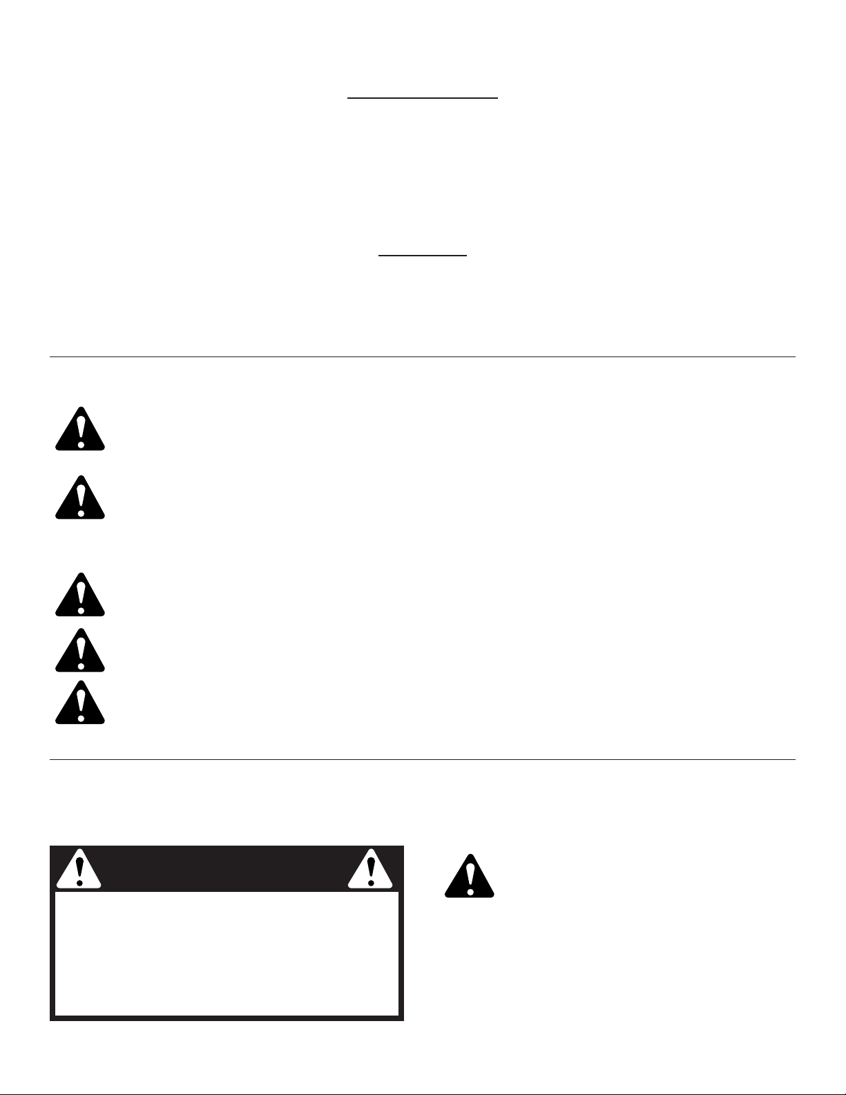
W
ARNING!
Read the Operator’s Manual and follow all warnings and safety instructions. Failure to do so can
result in serious injury to the operator and/or bystanders.
FOR QUESTIONS, CALL 1-800-345-8746 IN U.S. OR 1-800-668-1238 in CANADA
The purpose of safety symbols is to attract your attention to possible dangers. The safety symbols and
their explanations deserve your careful attention and understanding. The safety warnings do not by
themselves eliminate any danger. The instructions or warnings they give are not substitutes for proper
accident prevention measures.
SAFETY ALERT SYMBOL: Indicates danger, warning, or caution. Attention is required in order to avoid
serious personal injury. May be used in conjunction with other symbols or pictographs.
NOTE: Advises you of information or instructions vital to the operation or maintenance of the equipment.
DANGER: Failure to obey a safety warning will result in serious injury to yourself or to others. Always
follow the safety precautions to reduce the risk of fire, electric shock and personal injury.
WARNING: Failure to obey a safety warning can result in injury to yourself and others. Always follow
the safety precautions to reduce the risk of fire, electric shock and personal injury.
CAUTION: Failure to obey a safety warning may result in property damage or personal injury to
yourself or to others. Always follow the safety precautions to reduce the risk of fire, electric shock and
personal injury.
SECTION 1: IMPORTANT SAFE OPERATION PRACTICES
READ ALL INSTRUCTIONS
WARNING: When using the unit, you must
follow the safety rules. For your own safety
and that of bystanders, please read these
instructions before operating the unit.
Please keep the instructions for later use.
Before Operating
• Read the instructions carefully. Be familiar with the
controls and proper use of the unit.
• Do not operate this unit when tired, ill or under the
influence of alcohol, drugs or medication.
SECTION 1a:RULES FOR SAFE OPERATION
WARNING
California Proposition 65 Warning:
THE ENGINE EXHAUST FROM THIS
PRODUCT CONTAINS CHEMICALS
KNOWN TO THE STATE OF CALIFORNIA
TO CAUSE CANCER, BIRTH DEFECTS
OR OTHER REPRODUCTIVE HARM.

4
• Be aware of risk of injury to the head, hands and feet.
• Clear the area to be cut before each use. Remove
rocks, broken glass, nails, wire, string and other
objects which may be thrown or become entangled in
the cutting attachment. Clear the area of children,
bystanders and pets; keep them outside a 50-foot
(15 m.) radius, at a minimum. Even then, they are still
at risk from thrown objects. Encourage bystanders to
wear eye protection. If you are approached, stop the
unit immediately.
• Squeeze the throttle control and check that it returns
automatically to the idle position. Make all adjustments
or repairs before using the unit.
Safety Warnings for Gas Trimmers
WARNING: Gasoline is highly flammable,
and its vapors can explode if ignited. Take
the following precautions:
• Store fuel only in containers specifically designed and
approved for the storage of such materials.
• Always stop the engine and allow it to cool before
filling the fuel tank. Never remove the fuel tank cap or
add fuel when the engine is hot. Never operate the unit
without the fuel cap securely in place. Loosen the fuel
tank cap slowly to relieve any pressure in the tank.
• Add fuel in a clean, well-ventilated outdoor area where
there are no sparks or flames. Remove the fuel cap
slowly, and only after the engine stops. Do not smoke
while fueling or mixing fuel. Wipe up any spilled fuel
from the unit immediately.
• Avoid creating a source of ignition for spilled fuel. Do
not start the engine until fuel vapors dissipate.
• Move the unit at least 30 feet (9.1 m) from the fueling
source and site before starting the engine. Do not
smoke. Keep sparks and open flames away from the
area while adding fuel or operating the unit.
While Operating
• Never start or run the unit inside a closed room or
building. Breathing exhaust fumes can be fatal.
Operate this unit only in a well-ventilated outdoor area.
• Wear safety glasses or goggles that meet ANSI Z87.1
standards and are marked as such. Wear ear/hearing
protection when operating this unit. Wear a face or
dust mask if the operation is dusty.
• Wear heavy long pants, boots, gloves and a long
sleeve shirt. Do not wear loose clothing, jewelry, short
pants, sandals or go barefoot. Secure hair above
shoulder level.
• The cutting attachment shield must always be in place
while operating the unit. Do not operate unit without
both trimming lines extended, and the proper line
installed. Do not extend the trimming line beyond the
length of the shield.
• This unit has a clutch. The cutting attachment remains
stationary when the engine is idling. If it does not, have
the unit adjusted by an authorized service technician.
• Adjust the J-handle to your size in order to provide the
best grip.
• Be sure the cutting attachment is not in contact with
anything before starting the unit.
• Use the unit only in daylight or good artificial light.
• Avoid accidental starting. Remain in the starting
position whenever pulling the starter rope. The
operator and unit must be in a stable position while
starting. Refer to Starting/Stopping Instructions.
• Use the right tool. Only use this tool for its intended
purpose.
• Do not overreach. Always keep proper footing and
balance.
• Always hold the unit with both hands when operating.
Keep a firm grip on both handles or grips.
• Keep hands, face, and feet at a distance from all
moving parts. Do not touch or try to stop the cutting
attachment when it rotates.
• Do not touch the engine, gear housing or muffler.
These parts get extremely hot from operation, even
after the unit is turned off.
• Do not operate the engine faster than the speed
needed to cut, trim or edge. Do not run the engine at
high speed when not cutting.
• Always stop the engine when cutting is delayed or
when walking from one cutting location to another.
• If you strike or become entangled with a foreign
object, stop the engine immediately and check for
damage. Do not operate before repairing damage. Do
not operate the unit with loose or damaged parts.
• Stop the unit, switch the engine to off, and disconnect
the spark plug for maintenance or repair.
• Use only Genuine Factory Parts™ replacement parts
and accessories for this unit. These are available from
your authorized service dealer. Use of any unauthorized
parts or accessories could lead to serious injury to the
user, damage to the unit, and a voided warranty.
• Keep unit clean of vegetation and other materials.
They may become lodged between the cutting
attachment and shield.
• Children under the age of 15 must not use the unit;
teens may operate the unit with adult guidance.
• Inspect the unit before use. Replace damaged parts.
Check for fuel leaks. Make sure all fasteners are in
place and secure. Replace cutting attachment parts
that are cracked, chipped or damaged in any way.
Make sure the cutting attachment is properly installed
and securely fastened. Be sure that the cutting
attachment shield is properly attached, and positioned
as recommended. Failure to do so can result in
personal injury to the operator and bystanders, as well
as damage to the unit.
• Use only 0.095-inch (2.41 mm) diameter Genuine
Factory Parts™ replacement line. Never use metalreinforced line, wire, chain or rope. These can break
off and become dangerous projectiles.

5
• To reduce fire hazard, replace a faulty muffler and
spark arrestor. Keep the engine and muffler free from
grass, leaves, excessive grease or carbon build up.
While Operating with the Cutting Blade
• Read and understand all safety warnings before
operating this unit.
• Always use the shoulder harness when using the
brush blade accessory.
• Keep the J-handle between the operator and cutting
attachment or blade at all times.
• NEVER cut with the cutting blade located over 30
inches (76 cm) or more above the ground level.
• Blade thrust may occur when the spinning blade
contacts an object that it does not immediately cut.
Blade thrust can be violent enough to cause the unit
and/or operator to be propelled in any direction , and
possibly lose control of the unit. Blade thrust can
occur without warning if the blade snags, stalls or
binds. This is more likely to occur in areas where it is
difficult to see the material being cut.
• For operation with the brush blade, do not cut
anything thicker than 1/2 inch or a violent kickback
could occur.
• Do not attempt to touch or stop the blade when it is
rotating.
•A coasting blade can cause injury while it continues to
spin after the engine is stopped or the throttle trigger
is released. Maintain proper control until the blade has
completely stopped rotating.
• Do not run the unit at high speed when not cutting.
• If you strike or become entangled with a foreign
object, stop the engine immediately and check for
damage. Have any damage repaired before attempting
further operations. Do not operate unit with a bent,
cracked or dull blade. Discard blades that are bent,
warped, cracked or broken.
• Do not sharpen the cutting blade. Sharpening the blade
can cause the blade tip to break off while in use. This can
result in severe personal injury. Replace the blade.
• Do not use the cutting blade for edging or as an
edger, severe personal injury to yourself or others can
occur. Use the cutting blade only for the purpose as
described in this manual.
•Stop the engine IMMEDIATELY if you feel excessive
vibration. Vibration is a sign of trouble. Inspect thoroughly
for loose nuts, bolts or damage before continuing. Repair
or replace affected parts as necessary.
After Use
• Clean cutting blades with a household cleaner to
remove any gum buildup. Oil the blade with machine
oil to prevent rust.
• Lock up and store the cutting blade in an appropriate area
to protect the blade from unauthorized use or damage.
Other Safety Warnings
• Never store a fueled unit inside a building where fumes
may reach an open flame or spark.
• Allow the engine to cool before storing or transporting.
Be sure to secure the unit while transporting.
• Store the unit in a dry area, locked up or up high to
prevent unauthorized use or damage, out of the reach
of children.
• Never douse or squirt the unit with water or any other
liquid. Keep handles dry, clean and free from debris.
Clean after each use, see Cleaning and Storage
instructions.
• Keep these instructions. Refer to them often and use
them to instruct other users. If you loan someone this
unit, also loan them these instructions.
SAVE THESE INSTRUCTIONS

6
This operator's manual describes safety and international symbols and pictographs that may appear on this product.
Read the operator's manual for complete safety, assembly, operating and maintenance and repair information.
SECTION 1b:SAFETY & INTERNATIONAL SYMBOLS
SYMBOL MEANING
• ON/OFF STOP CONTROL
OFF or STOP
• THROWN OBJECTS AND
ROTATING CUTTER CAN
CAUSE SEVERE INJURY
WARNING:
Do not operate without
the cutting attachment shield in place.
Keep away from the rotating cutting
attachment.
• HOT SURFACE WARNING
Do not touch a hot muffler, gear housing
or cylinder. You may get burned. These
parts get extremely hot from operation.
They remain hot for a short time after the
unit is turned off.
• SHARP BLADE
WARNING: Sharp blade on cutting
attachment shield. To prevent serious
injury, do not touch line cutting blade.
• BRUSHCUTTERS • REPLACE
DULL BLADE
Do not sharpen the cutting blade.
Sharpening the blade can cause the
blade tip to break off while in use. This
can result in severe personal injury.
•TRIMMER/BRUSHCUTTER
SAFETY
WARNING: Thrown objects and
rotating cutter can cause severe injury.
Keep bystanders, especially children
and pets, at least 50 feet (15 m) away
from the cutting area. The cutting
attachment shield must be used when
using the trimmer cutting attachment.
• CHOKE CONTROL
A • FULL choke position
B • PARTIAL choke position
C • RUN position
SYMBOL MEANING
• SAFETY ALERT SYMBOL
Indicates danger, warning or caution.
May be used in conjunction with other
symbols or pictographs.
•WARNING - READ
OPERATOR'S MANUAL
Read the operator’s manual(s) and follow
all warnings and safety instructions.
Failure to do so can result in serious injury
to the operator and/or bystanders.
• WEAR EYE AND HEARING
PROTECTION
WARNING:
Thrown objects and loud
noise can cause severe eye injury and
hearing loss. Wear eye protection
meeting ANSI Z87.1 standards and ear
protection when operating this unit.
Use a full face shield when needed.
•KEEP BYSTANDERS AWAY
WARNING:
Keep all bystanders,
especially children and pets, at least
50 feet (15 m) from the operating area.
• UNLEADED FUEL
Always use clean, fresh unleaded fuel.
• OIL
Refer to operator's manual for the
proper type of oil.
•ON/OFF STOP CONTROL
ON / START / RUN
• PRIMER BULB
Push primer bulb, fully and slowly,
10 times.
7
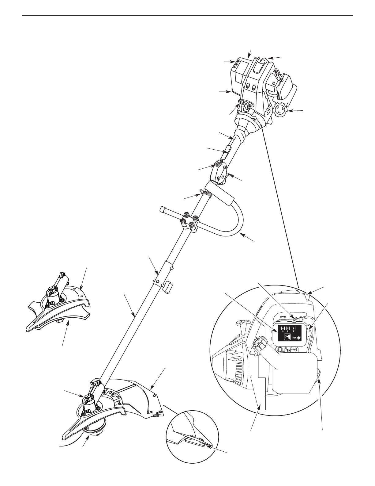
SECTION 2: KNOW YOUR UNIT
Primer Bulb
Choke Lever
Oil Fill Plug / Dipstick
Air Filter Cover
Engine Feet
Spark Plug
Applications
As a trimmer:
• Cutting grass and light weeds
• Edging
• Decorative trimming around trees, fences, etc.
As a brushcutter:
• Cutting weeds and light bush of up to 1/2 inch in
diameter
Other optional accessories may be used with the
YM26BC. Refer to Operating the EZ-Link System for a
list of add-ons.
Cutting Attachment
Shield
Fuel Cap
Throttle
Control
Throttle
Lock-Out
J-Handle
Cutting Attachment
Gear
Housing
Shaft Grip
On/Off Stop Control
Shaft
Housing
Starter Rope Grip
EZ-Link™
Blade Shield /
Shield Mount
Brush
Blade
Line Cutting Blade
Spark Plug
Muffler
Muffler Guard
Spark Arrestor
Shoulder Strap Clip
8
SECTION 3: ASSEMBLY INSTRUCTIONS
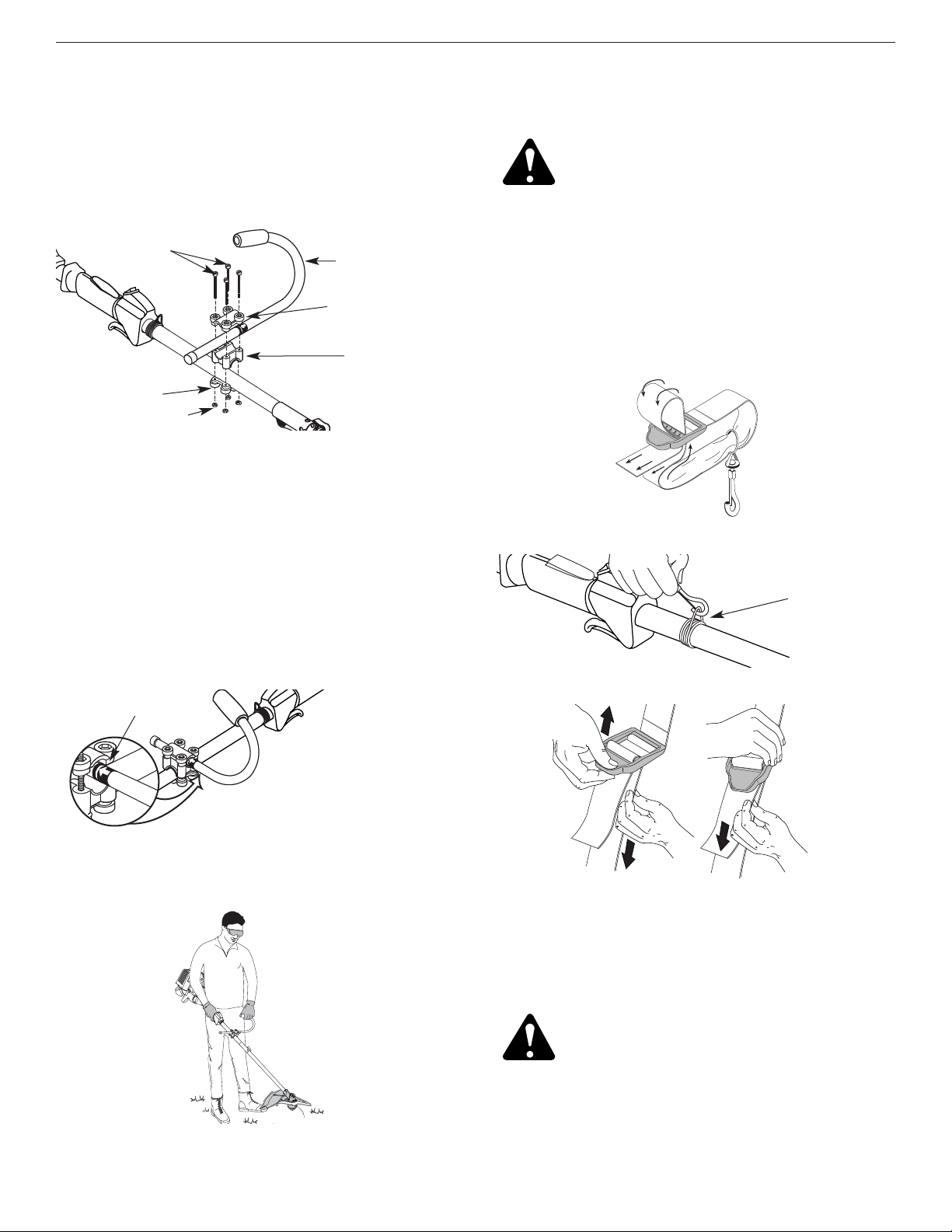
Figure 1
Figure 2
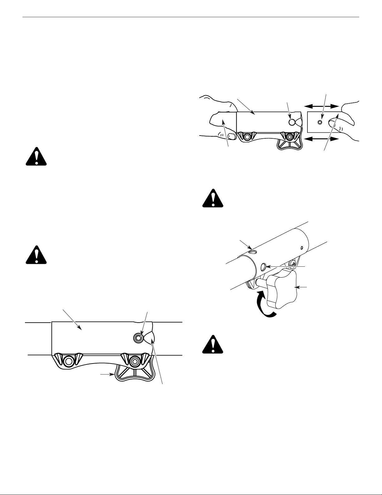
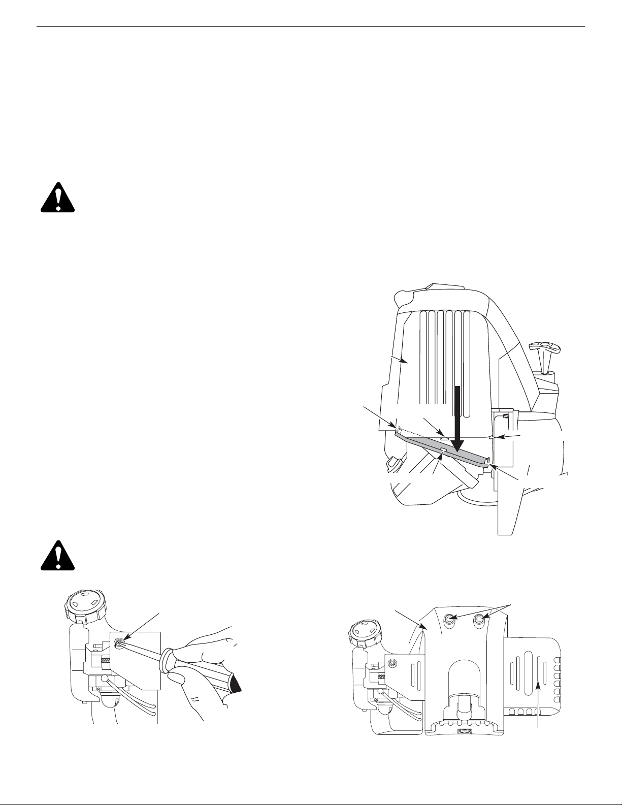
On some units, the J-handle may be pre-installed. Go to
step 5 if the J-handle is pre-installed.
Install and Adjust the J-handle
1. Place the J-handle between the top and middle
clamp pieces. See Figure 1.
2. While holding the three pieces together, install the four
(4) screws through the top clamp and into middle clamp.
NOTE: The holes in the top and middle clamp will line
up only when assembled correctly.
3. Place the clamps and the J-handle over the shaft
housing and onto the bottom clamp.
4. Hold each hex nut in the bottom clamp recess with a
finger. Start screws with a large Phillips screwdriver.
Do not tighten until you make the handle adjustment.
5. Slide the J-handle in or out until the arrow/white line on the
decal touches the clamp assembly. You must first loosen
the screws if the handle is pre-installed. See Figure 2.
6. While holding the unit in the operating position,
position the J-handle to the location that provides you
the best grip. See Figure 3.
7. Tighten the clamp screws evenly, until the J-handle
is secure.
Figure 3
(4) Screws
Top Clamp
J-Handle
Middle Clamp
Bottom Clamp
Nuts
Decal
Figure 4
Support Fitting
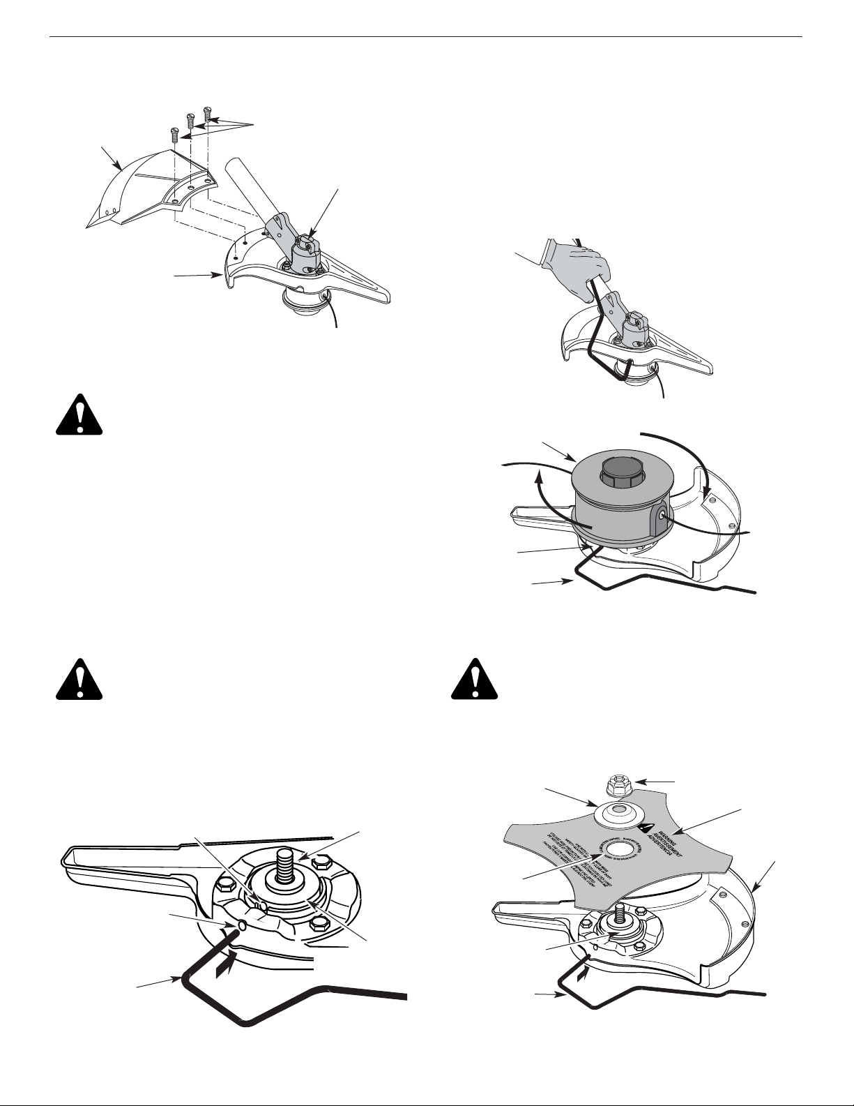
Remove and Install the Cutting Attachment
Shield
Remove the cutting attachment shield when using the
unit as a brushcutter
Remove the cutting attachment shield from the shield
mount by removing the three (3) screws with a flat blade
screwdriver. See Figure 7. Store parts for future use.
Install the Harness
1. Push the strap through the center of the buckle.
2. Pull the strap over the cross bar and down through
the slot in the buckle. See Figure 4.
3. Put the harness on over head and onto shoulder.
Snap it on to the support fitting. See Figure 5.
4. Adjust length to fit the operator’s size. Pull tab to
lengthen, pull strap to shorten. See Figure 6.
WARNING: Always use the shoulder
harness when using the cutting blade to
avoid serious personal injury.
Figure 6
WARNING: The cutting attachment shield
should NOT be installed when operating the
unit with a blade. Remove the cutting
attachment shield before removing or
installing the blade.
Figure 5
9
Install the cutting attachment shield when using the unit
as a grass trimmer
Install the cutting attachment shield on the shield mount by
inserting the three (3) screws into the shield mount. Tighten
securely with a flat blade screwdriver. See Figure 7.
Remove the Cutting Attachment & Install
the Cutting Blade
NOTE: To make cutting blade removal and installation easier,
place the unit on the ground or on a work bench
.
Remove the Cutting Attachment Shield
See Remove and Install the Cutting Attachment Shield.
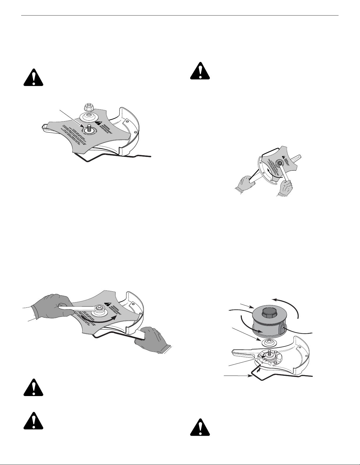
Remove the Cutting Attachment
1. Align the shaft bushing hole with the locking rod slot
and insert the locking rod into the shaft bushing hole.
See Figure 8.
(3) Screws
Cutting
Attachment
Shield
Shield Mount
Gear Housing
Cutting Attachment
Locking Rod
Slot
Locking Rod
Shaft Bushing Hole
Locking Rod Slot
Output Shaft
Bushing
Locking Rod
Output Shaft
2. Hold the locking rod in place by grasping it next to
the boom of the unit. See Figure 9.
3. While holding the locking rod, remove the cutting
attachment by turning it clockwise off of the output shaft.
See Figure 10.
Store the cutting attachment for future use.
NOTE: The blade retainer under the cutting attachment
will be used when installing the cutting blade.
Install the Cutting Blade
4. Place the cutting blade on the output shaft bushing.
See Figure 11.
Shield
Mount
Locking Rod
Cutting
Blade
Blade Retainer
Nut
Output Shaft
Bushing
Pilot Hole
SECTION 3: ASSEMBLY INSTRUCTIONS
WARNING: To avoid serious personal
injury, the cutting attachment shield MUST
be in place at all times while operating the
unit as a grass trimmer.
WARNING: The gear housing gets hot with
use. It can result in injury to the operator.
The housing remains hot for a short time
even after the unit is turned off. Do not
touch the gear housing until it has cooled.
WARNING:
To avoid serious personal
injury, always wear gloves while handling or
installing the blade.
Figure 10
Figure 9
Figure 8
Figure 7
Figure 11
10
SECTION 3: ASSEMBLY INSTRUCTIONS
Pilot Step
Remove the Cutting Blade & Install the
Cutting Attachment
Remove the Cutting Blade
1. Align the shaft bushing hole with the locking rod slot and
insert the locking rod into the bushing hole. See Figure 8
.
2. Hold the locking rod in place by grasping it next to
the boom of the unit. See Figure 14.
3. While holding the locking rod, loosen the nut on the
blade by turning it clockwise with a 5/8 inch closedend or socket wrench. See Figure 14.
9. Remove the locking rod from the locking rod slot.
1/4-1/2 turn
Counterclockwise
6. Align the shaft bushing hole with the locking rod
slot and insert the locking rod into the bushing hole.
See Figure 8.
7. Put the blade retainer and nut on the output shaft.
Make sure that the blade is installed correctly.
8. Tighten nut counterclockwise against the blade while
holding the locking rod:
• If using a torque wrench and an 5/8 inch socket tighten
to: 325 - 335 in•lb, 27 - 28 ft.•lb, 37 - 38 N•m.
• Without a torque wrench, use a 5/8 inch closed-end or
socket wrench, turning the nut until the blade retainer is
snug against the shaft bushing. Make sure that the blade
is installed correctly, then rotate the nut an additional 1/4
to 1/2 turn counterclockwise. See Figure 13.
Cutting Attachment
Locking Rod
Clockwise
6. Remove the locking rod.
7. Install the cutting attachment shield. Refer to Remove
and Install the Cutting Attachment Shield.
Blade Retainer
Output Shaft
Bushing
5. Make sure that the cutting blade is centered on the
pilot step and sitting flat against the output shaft
bushing. See Figure 12.
4. Remove the nut, blade retainer and blade. Store the
nut and blade together for future use in a secure
place. Store out of children’s reach.
Install the Cutting Attachment
5.
Align the shaft bushing hole with the locking rod slot and
insert the locking rod into the shaft bushing hole.
See
Figure 8.
Place the blade retainer on the output shaft
with the flat surface against the output shaft bushing.
See
Figure 15.
Screw the cutting attachment
counterclockwise onto the output shaft. Tighten securely.
NOTE: The blade retainer must be installed on the output
shaft in the position shown for the cutting
attachment to work correctly.
WARNING:
To avoid serious personal
injury or damage to the unit, do not start or
operate this unit with the locking rod in the
locking rod slot.
WARNING: Do not sharpen the cutting blade.
Sharpening the blade can cause the blade tip
to break off while in use. This can result in
severe personal injury. Replace the blade.
WARNING: If the cutting blade is off-
center, the unit will vibrate and the blade
may fly off, causing possible serious
personal injury.
WARNING: To avoid serious personal
injury, the cutting head guard MUST be in
place at all times while operating the unit
as a trimmer.
WARNING: To avoid serious personal
injury, always wear gloves while handling or
installing the blade.
Figure 14
Figure 15
Figure 12
Figure 13
11
SECTION 4: OIL AND FUEL INFORMATION
DANGER: OVERFILLING OIL CRANKCASE
MAY CAUSE SERIOUS PERSONAL INJURY.
Check and maintain the proper oil level in
the crank case; it is important and cannot
be overemphasized. Check the oil before
each use and change it as needed. See
Changing the Oil.
Recommended Oil Type
Using the proper type and weight of oil in the crankcase
is extremely important. Check the oil before each use
and change the oil regularly. Failure to use the correct
oil, or using dirty oil, can cause premature engine wear
and failure.
Use a high-quality SAE 30 weight oil of API (American
Petroleum Institute) service class SF, SG, SH.
Adding Oil to Crankcase:Initial Use
NOTE: This unit is shipped without oil. In order to avoid
damage to the unit, put oil in the crankcase
before you attempt to start the unit.
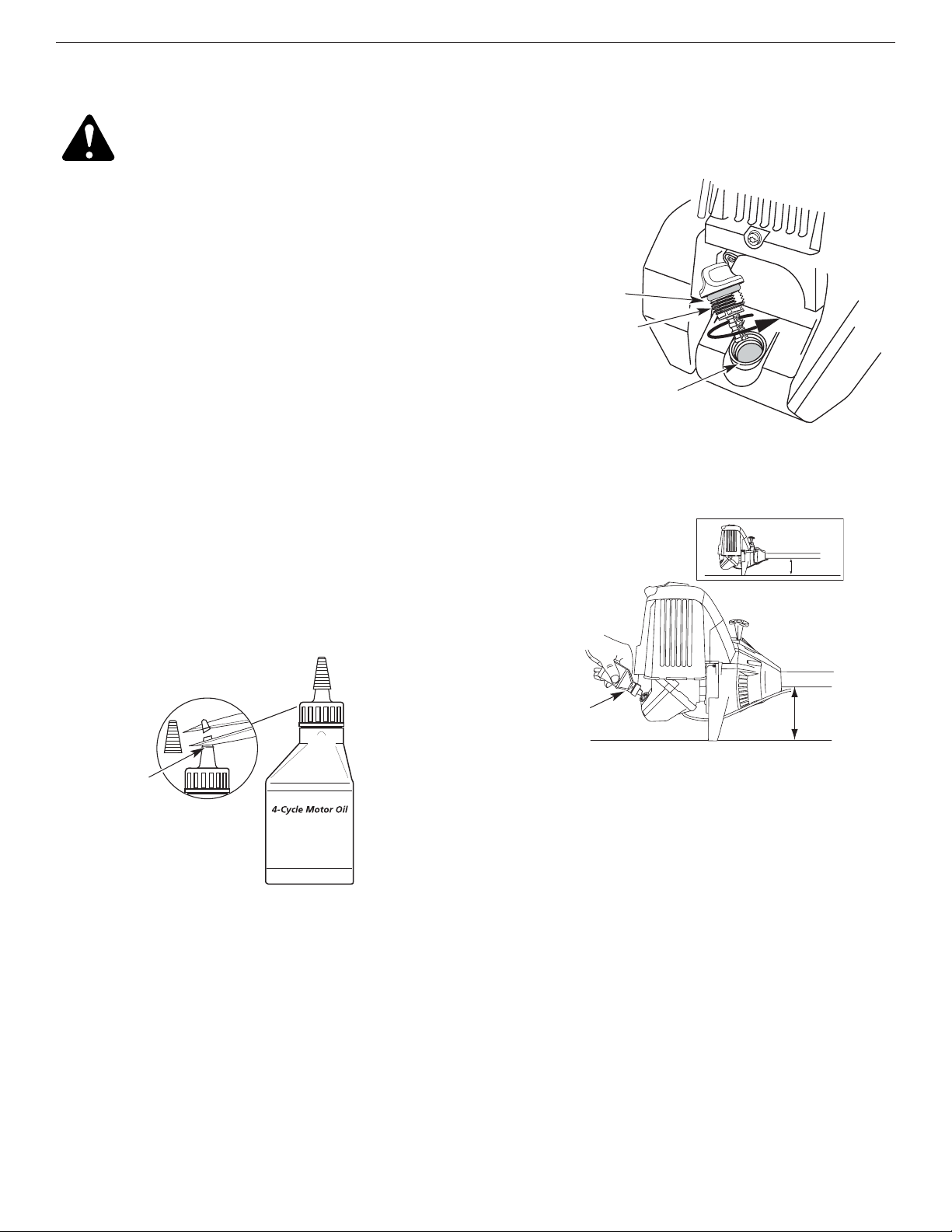
Your unit is supplied with one 3.4 fluid oz. (100 ml.)
bottle of SAE 30 SF, SG, SH oil. See Figure 16.
NOTE: Save the bottle of oil. It can be used to measure
the correct amount during future oil changes.
See Changing the Oil.
1. Unscrew the top of the bottle of oil and remove the
paper seal covering the opening. Replace the top.
Next, cut the tip off the funnel spout. See Figure 16.
2. Place the unit on a flat level surface.
3. Remove the oil plug / dipstick from the crankcase.
See Figure 17.
Oil Fill
NOTE: Never add oil to the fuel or fuel tank.
5. Wipe up any oil that may have spilled and reinstall
the oil fill plug / dipstick.
Check oil before each use and change as needed. Refer
to Changing the Oil.
Oil Fill Plug/Dipstick
Oil Fill Hole
4. Pour the entire bottle of oil into the oil fill hole. See
Figure 18.
O-Ring
Funnel Spout
Figure 16
Figure 18
Figure 17
12
SECTION 4: OIL AND FUEL INFORMATION
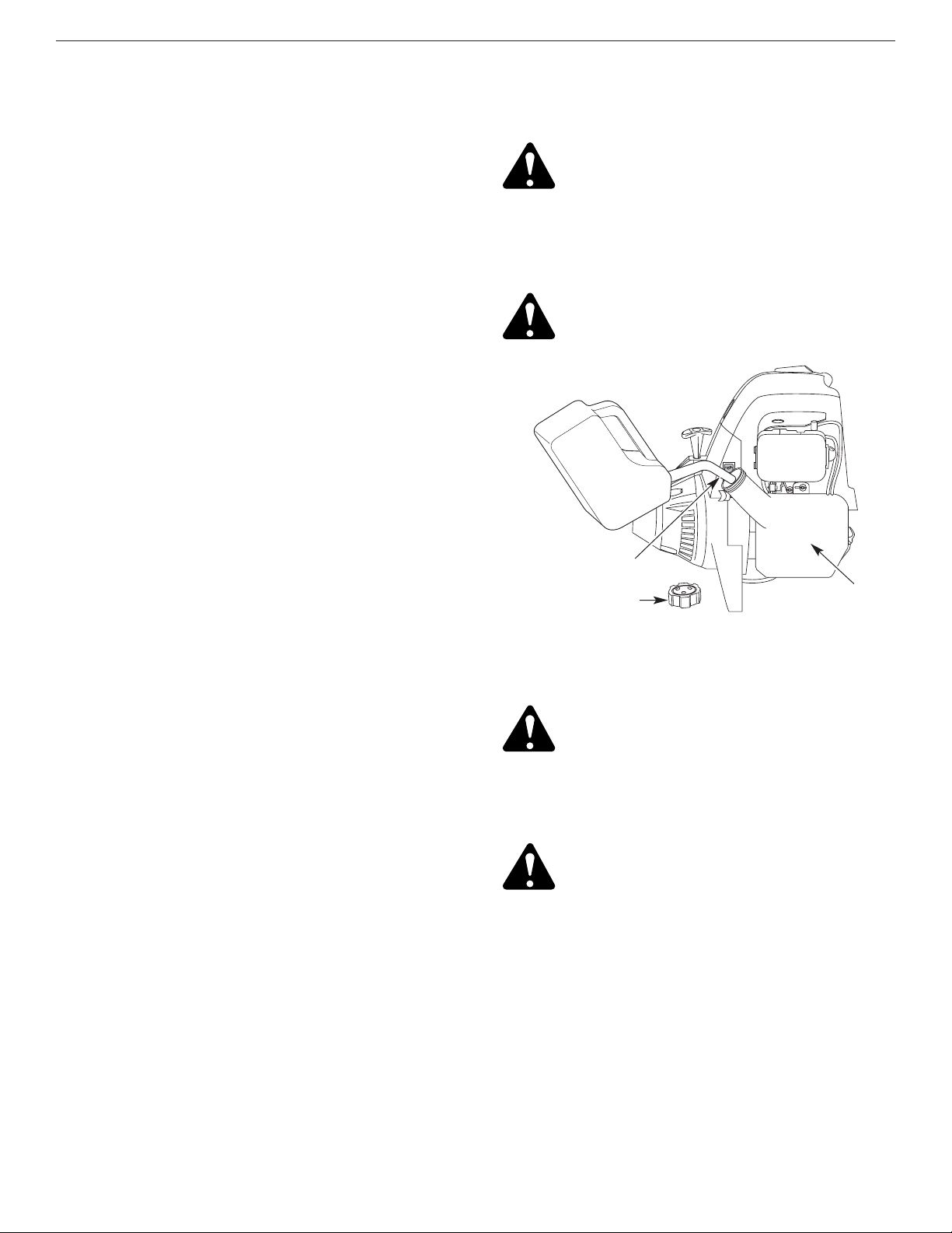
Fueling The Unit
1. Remove the fuel cap.
Fuel Cap
Fuel Tank
Gas Can Spout
2. Place the gas container’s spout into the fill hole on
the fuel tank and fill the tank. See Figure 19.
NOTE: Do not overfill the tank.
3. Wipe up any gasoline that may have spilled.
4. Reinstall the fuel cap.
5. Move the unit at least 30 ft. (9.1 m) from the fueling
source and site before starting the engine.
NOTE: Dispose of the old gasoline in accordance to
Federal, State and Local regulations.
Recommended Fuel Type
Old fuel is the primary reason for improper unit
performance. Be sure to use fresh, clean, unleaded
gasoline.
NOTE: This is a four cycle engine. In order to avoid
damage to the unit, do not mix oil with
gasoline.
Definition of Blended Fuels
Today's fuels are often a blend of gasoline and
oxygenates such as ethanol, methanol or MTBE (ether).
Alcohol-blended fuel absorbs water. As little as 1%
water in the fuel can make fuel and oil separate or form
acids when stored. Use fresh fuel (less than 60 days
old), when using alcohol-blended fuel.
Using Blended Fuels
If you choose to use a blended fuel, or its use is
unavoidable, follow recommended precautions:
• Always use fresh unleaded gasoline
• Use the fuel additive STA-BIL®or an equivalent
• Drain tank and run the engine dry before storing unit
Using Fuel Additives
The use of fuel additives, such as STA-BIL®Gas
Stabilizer or an equivalent, will inhibit corrosion and
minimize the formation of gum deposits. Using a fuel
additive can keep fuel from forming harmful deposits in
the carburetor for up to six (6) months. Add 0.8 oz.
(23 ml.) of fuel additive per gallon of fuel according to the
instructions on the container. NEVER add fuel additives
directly to the unit's gas tank.
Unleaded
Gasoline
Figure 19
WARNING: Gasoline is extremely flammable
and its vapors can explode if ignited. To avoid
serious personal injury, always stop the engine
and allow it to cool before filling the fuel tank.
Do not smoke while filling the tank. Keep
sparks and open flames away from the area.
WARNING: Remove the fuel cap slowly to
avoid injury from gasoline spray.
WARNING: Add gasoline in a clean, wellventilated outdoor area. Avoid creating a
source of ignition for spilt fuel.
WARNING: Never operate the unit without
the fuel cap securely in place.
13
SECTION 5: STARTING/STOPPING INSTRUCTIONS
Starting Instructions
Cold Start:The Day’s First Start or Engine Ran Out of Gas
WARNING: Operate this unit only in a wellventilated outdoor area. Carbon monoxide
exhaust fumes can be lethal in a confined area
.
1. Check oil level in crankcase. See Checking the Oil Level.
2. Fill the fuel tank with fresh, clean, unleaded gasoline.
See Fueling the Unit.
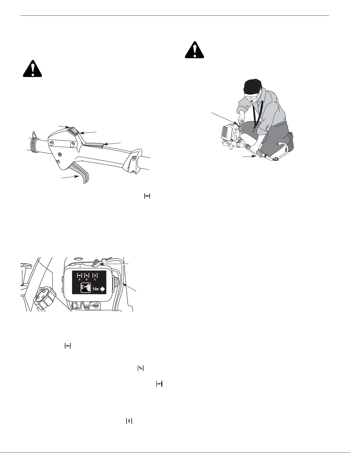
3. Put the Start/Stop Engine Control in the START [I]
position. See Figure 20.
Stopping Instructions
1. Release your hand from the throttle control. See
Figure 22. Allow the engine to cool down by idling.
2. Put the On/Off Stop Control in the OFF (O) position.
See Figure 20.
Primer Bulb
Choke Lever
Starter Rope
Throttle Control
WARNING: Avoid accidental starting. Make
sure you are in the starting position when
pulling the starter rope. See Figure 22. To
avoid serious injury, the operator and unit
must be in a stable position while starting.
4. Place the choke lever in the FULL choke (A)
position. See Figure 21.
NOTE:
Slide the choke lever directly above the appropriate
symbol on filter cover decal. See Figure 21.
5. Fully press and release the primer bulb slowly 10
times until FUEL IS VISIBLE IN THE PRIMER
BULB. If you can’t see fuel in the bulb, press and
release the bulb as many times as it takes before you
can see fuel in it. See Figure 21.
6. Squeeze the throttle control to the wide open (full
throttle) position and squeeze the throttle lock-out.
7. With the unit in the starting position and the choke in
the FULL (A) position, pull the starter rope briskly
5 times. If the engine attempts to run before the fifth
pull, proceed to step 8.
8. Move the choke lever to the PARTIAL (B)
position. See Figure 21.
NOTE: The engine will not run in the FULL choke (A)
position.
9. Pull the starter rope 1 to 3 pulls until the engine
starts. Run for 15-30 seconds. If the unit fails to
start, return to step 4.
10. Move the choke lever to the RUN (C) position and
run at full throttle for 30 seconds.
11. Release the throttle control to the idle position and
begin operation.
NOTE: If the engine does not start using these
procedures, repeat steps 4 through 11 using
TWO (2) pulls in the FULL choke (A) position.
Engine Re-Start:Warm Engine With Fuel
1. Put the Start/Stop Engine Control in the START [I]
position. See Figure 20.
2. Move the choke lever to the PARTIAL (B) position.
See Figure 21.
3. Fully press and release the primer bulb slowly 10
times until FUEL IS VISIBLE IN THE PRIMER
BULB. If you can’t see fuel in the bulb, press and
release the bulb as many times as it takes before you
can see fuel in it. See Figure 21.
4. Squeeze the throttle control to the wide open (full
throttle) position.
5. With the unit in the starting position, pull the starter
rope briskly until the engine starts. See Figure 22.
6. When the engine starts, move the choke lever to the
RUN (C) position, and run at full throttle for 30
seconds.
NOTE: If the engine does not start using the Engine
Re-start procedures, revert to the Cold Start
procedures.
Figure 22
Figure 21
Start/On (I)
Stop/Off (O)
Throttle Lock-Out
Throttle Control
Figure 20
14
For edging (when using the line head cutting attachment
with EZ-Link™ models), lock the release button of the
cutting attachment into the 90° edging hole or the 180°
edging hole. See Figure 25.
Operating the EZ-Link™ System
The EZ-Link™ system enables the use of these optional
Add-Ons:
Blower/Vacuum . . . . . . . . . . . . . . . . . . . . . . . . . . BV720r
Cultivator . . . . . . . . . . . . . . . . . . . . . . . . . . . . . . GC720r
Edger . . . . . . . . . . . . . . . . . . . . . . . . . . . . . . . . . . LE720r
Hedge Trimmer . . . . . . . . . . . . . . . . . . . . . . . . . . HS720r
Snow Thrower . . . . . . . . . . . . . . . . . . . . . . . . . . . ST720r
Straight Shaft Trimmer . . . . . . . . . . . . . . . . . . . . SS725r
Tree Pruner . . . . . . . . . . . . . . . . . . . . . . . . . . . . . TP720r
Turbo Blower . . . . . . . . . . . . . . . . . . . . . . . . . . . . TB720r
Removing the Cutting Attachment or Add-Ons
1. Turn the knob counterclockwise to loosen. See Figure 23.
2. Press and hold the release button. See Figure 23.
3. While firmly holding the upper shaft housing, pull
the cutting attachment or add-on straight out of the
EZ-Link™ coupler. See Figure 24.
Installing the Cutting Attachment or Add-On
NOTE: Place the unit on the ground or on a work bench
to make add-on installation or removal easier.
1. Turn knob counterclockwise to loosen.
EZ-Link™ Coupler
Release Button
Guide Recess
Knob
Primary Hole
Upper Shaft Housing
EZ-Link™ Coupler
2. While firmly holding the add-on, push it straight into
the EZ-Link™ coupler. See Figure 24.
NOTE: Aligning the release button with the guide recess
will help installation. See Figure 23.
3. Turn the knob clockwise to tighten. See Figure 25.
Knob
Lower Shaft Housing
Release Button
90˚ Edging Hole
(Trimmer Only)
180˚ Edging Hole
(Trimmer Only)
CAUTION: Lock the release button in the
primary hole and securely tighten the knob
before operating this unit
SECTION 6: OPERATING INSTRUCTIONS
Figure 25
Figure 24
Figure 23
CAUTION:
The cutting attachment and addons with the EZ-Link™ system are to be used
in the primary hole unless stated otherwise in
the specific add-ons operator’s manual.
Using the wrong hole could lead to personal
injury or damage to the unit.
WARNING: Read and understand the
operator’s manual for each add-on prior to
operation.
WARNING: To avoid serious personal injury
and damage to the unit, shut off the unit
before removing or installing add-ons.
15
SECTION 6: OPERATING INSTRUCTIONS
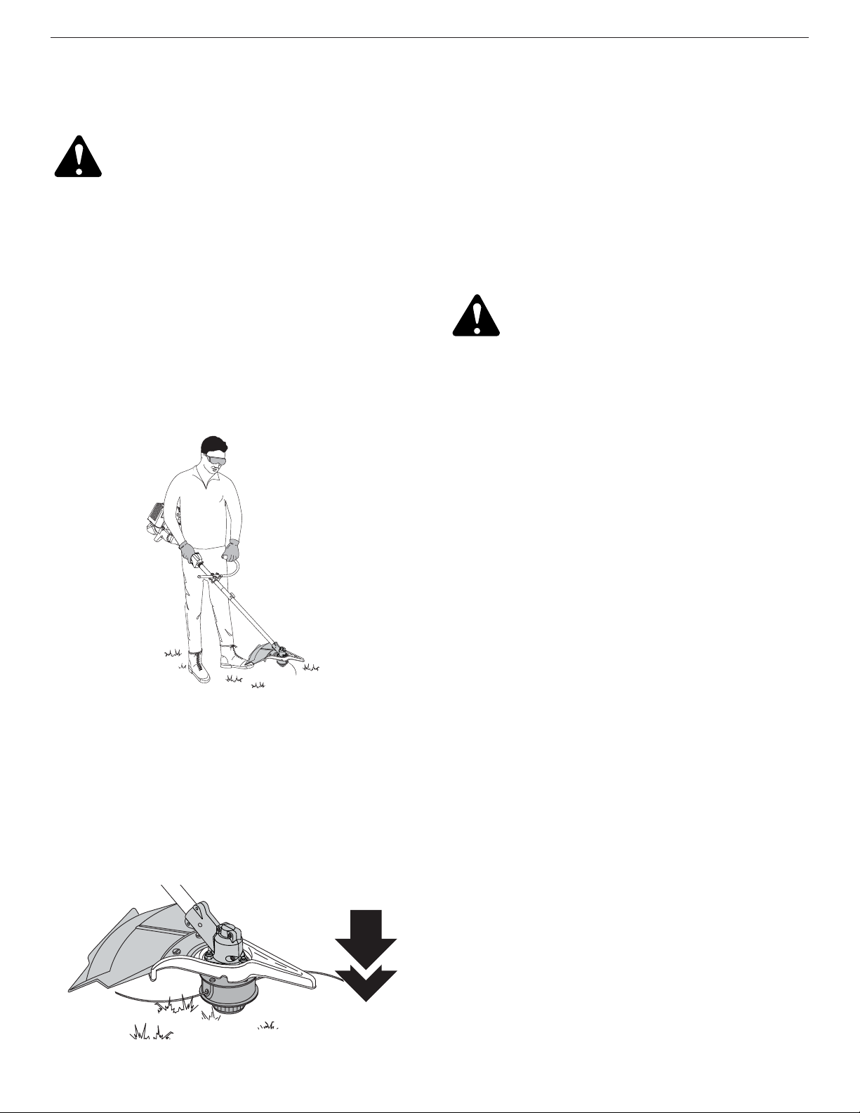
Holding the Trimmer
WARNING: Always wear eye, hearing, foot
and body protection to reduce the risk of
injury when operating this unit.
Before operating the unit, stand in the operating
position. See Figure 26. Check for the following:
• The operator is wearing eye protection and proper
clothing
• With a slightly-bent right arm, the operator’s right hand
is holding the shaft grip
• The operator’s left arm is straight, the left hand holding
the J-handle
• The unit is at waist level
•
The cutting attachment is parallel to the ground and
easily contacts the grass without the need to bend ove
r
Once you are in the operating position, hook the
shoulder strap to the unit.
Adjusting Trimming Line Length
The Bump Head™ cutting attachment allows you to release
trimming line without stopping the engine. To release more
line, lightly tap the cutting attachment on the ground while
operating the trimmer at high speed. See Figure 27.
NOTE: Always keep the trimming line fully extended.
Line release becomes more difficult when the
cutting line gets shorter.
Each time the head is bumped, about 1 inch (25.4 mm)
of trimming line releases. A blade in the cutting
attachment shield will cut the line to the proper length if
any excess line is released.
For best results, tap the bump knob on bare ground or
hard soil. If you attempt a line release in tall grass, the
engine may stall. Always keep the trimming line fully
extended. Line release becomes more difficult when the
cutting line gets shorter.
NOTE: Do not rest the bump knob on the ground while
the unit is running.
CAUTION: Do not remove or alter the line
cutting blade assembly. Excessive line
length may make the unit overheat.
Some line breakage will occur from:
• Entanglement with foreign matter
• Normal line fatigue
• An attempt to cut thick, stalky weeds
•
Forcing the line into objects such as walls or fence posts
Tips for Best Trimming Results
• For best trimming results, operate unit at full throttle.
• Keep the cutting attachment parallel to the ground.
• Do not force the cutting attachment. Allow the tip of
the line to do the cutting, especially along walls.
Cutting with more than the tip will reduce cutting
efficiency and may overload the engine.
• Cut grass over 8 inches (200 mm) tall by working
from top to bottom in small increments to avoid
premature line wear or engine drag.
• Cut from left to right whenever possible. Cutting to
the right improves the unit's cutting efficiency.
Clippings are thrown away from the operator.
• Slowly move the trimmer into and out of the cutting
area at the desired height. Move either in a forwardto-backward or side-to-side motion. Cutting shorter
lengths produces the best results.
• Trim only when grass and weeds are dry.
• The life of your cutting line is dependent upon:
• Following the trimming techniques
• What vegetation is being cut
• Where vegetation is cut
For example, the line will wear faster when trimming
against a foundation wall as opposed to trimming
around a tree.
Figure 26
Figure 27
16
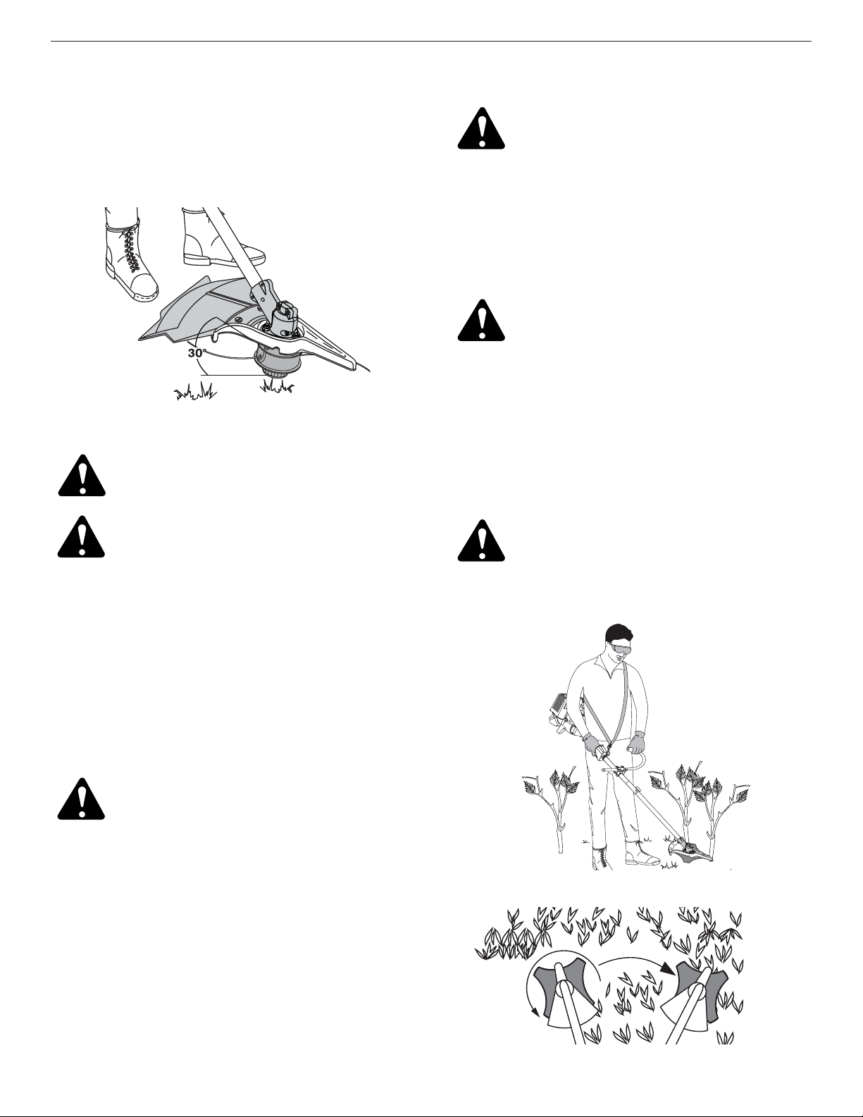
Decorative Trimming
Decorative trimming refers to the removal of vegetation
around trees, posts, fences and more.
Rotate the whole unit so that the cutting attachment is at
a 30° angle to the ground. See Figure 28.
Figure 28
Using the Cutting Blade
Before operating the unit with the cutting blade, stand in
the operating position. See Figure 29. Refer to Holding
the Trimmer.
Cutting Blade Operating Tips
To establish a rhythmic cutting procedure:
• Plant feet firmly, comfortably apart.
• Bring the engine to full throttle before entering the
material to be cut. At full throttle the blade has
maximum cutting power and is less likely to bind, stall
or cause blade thrust (which can result in serious
personal injury to the operator or others).
• Cut while swinging the upper part of your body from
left to right.
• Always release the throttle trigger and allow the engine
to return to idle speed when not cutting.
• When you are finished, always unsnap the unit from
the harness before taking off the harness.
• Swing the unit in the opposite direction as the blade
spins, which increases the cutting action.
• After the return swing, move forward to the next area
to be cut plant your feet again.
• The cutting blade is designed with a second cutting
edge. You can use it by removing the blade, turning it
upside down, and reinstalling it.
To reduce the chance of material wrapping around the
blade, follow these steps:
• Cut at full throttle
• Swing the unit into material to be cut from your left to
your right, see Figure 30
• Avoid the material just cut as you make the return swing
WARNING: Do not clear away any cut
material with the engine running or blade
turning. To avoid serious personal injury,
turn off the engine. Allow the blade to stop
before removing materials wrapped around
the blade shaft.
WARNING: Do not sharpen the cutting
blade. Sharpening the blade can cause the
blade tip to break off while in use. This can
result in severe personal injury to yourself
or others. Replace the blade.
WARNING: The blade continues to spin after
the engine is turned off. The coasting blade
can seriously cut you if accidentally touched.
WARNING: Blade thrust may occur when
the spinning blade contacts an object that
it does not immediately cut. Blade thrust
can be violent enough to cause the unit
and/or operator to be propelled in any
direction, and possibly lose control of the
unit. Blade thrust can occur without
warning if the blade snags, stalls or binds.
This is more likely to occur in areas where
it is difficult to see the material being cut.
WARNING: Do not use the cutting blade for
edging or as an edger. Severe personal
injury to yourself or others can result.
WARNING: Always wear eye, hearing, foot, body
protection and the shoulder strap to reduce the
risk of injury when operating this unit.
Figure 30
Figure 29
SECTION 6: OPERATING INSTRUCTIONS
17
SECTION 7: MAINTENANCE AND REPAIR INSTRUCTIONS
WARNING: To prevent serious injury, never
perform maintenance or repairs with unit
running. Always service and repair a cool
unit. Disconnect the spark plug wire to
ensure that the unit cannot start.
Maintenance Schedule
Perform these required maintenance procedures at the
frequency stated in the table. These procedures should
also be a part of any seasonal tune-up.
NOTE: Some maintenance procedures may require
special tools or skills. If you are unsure about
these procedures take your unit to any non-road
engine repair establishment, individual or
authorized service dealer.
NOTE: Maintenance, replacement, or repair of the emission
control devices and system may be performed by
any non-road engine repair establishment, individual
or authorized service dealer.
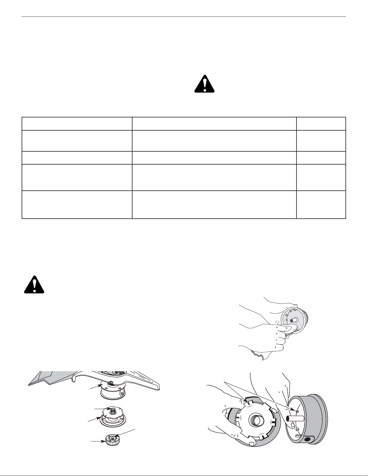
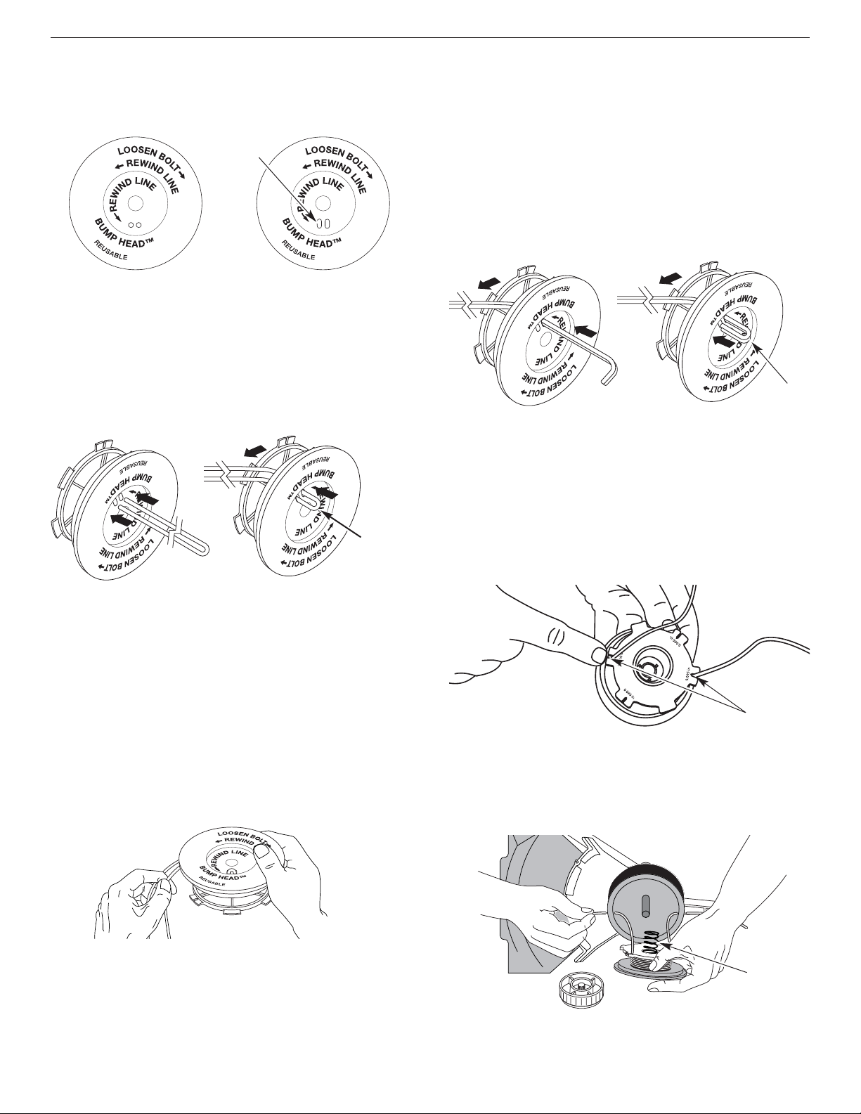
Line Installation
This section covers both SplitLine™ and standard single
line installation.
Always use Genuine Factory Parts™ 0.095 in. (2.41 mm)
replacement line. Using line other than the specified may
make the engine overheat or fail.
WARNING: Never use metal-reinforced line,
wire, chain or rope. These can break off
and become dangerous projectiles.
There are two methods to replace the trimming line:
• Wind the inner reel with new line
• Install a prewound inner reel
Winding the Existing Inner Reel
1. Hold the outer spool with one hand and unscrew the
bump knob counterclockwise. See Figure 31. Inspect
the bolt inside the bump knob to make sure it moves
freely. Replace the bump knob if damaged.
Figure 31
FREQUENCY MAINTENANCE REQUIRED REFER TO
Before starting engine
Fill fuel tank with fresh fuel
Check oil
Page 12
Page 19
Every 10 hours Clean and re-oil air filter Page 21
First change at 10 hours
Every 25 hours thereafter
Every 25 hours
Change oil
Change oil
Clean spark arrestor
Page 20
Page 20
Page 24
10 hours on new engine
Every 25 hours
Every 25 hours
Check rocker arm to valve clearance and adjust
Check rocker arm to valve clearance and adjust
Check spark plug condition and gap
Page 23
Page 23
Page 24
2. Remove the inner reel from the outer spool. See
Figure 31.
3. Remove spring from the inner reel. See Figure 31.
4. Use a clean cloth to wipe the inner reel, spring, shaft,
and inner surface of the outer spool. See Figure 32.
5. Check the indexing teeth on the inner reel and outer
spool for wear. If necessary, remove burrs or replace
the reel and spool. See Figure 33.
Inner Reel
Spring
Outer Spool
Bump Knob
Bolt
Indexing Teeth
Figure 33
Figure 32
18
SECTION 7: MAINTENANCE AND REPAIR INSTRUCTIONS
NOTE: SplitLine™ can only be used with the inner reel
with the slotted holes. Single line can be used on
either type of inner reel. Use Figure 34 to identify
the inner reel you have.
NOTE: Always use the correct line length when installing
trimming line on the unit. The line may not release
properly if the line is too long.
Single Line Installation
Go To Step 8 for SplitLine™ Installation
6. Take approximately 40 feet (12.2 m) of new trimming
line, loop it into two equal lengths. Insert each end of
the line through one of the two holes in the inner reel.
See Figure 35. Pull the line through the inner reel so
that the loop is as small as possible.
7. Wind the lines in tight even layers, onto the reel. See
Figure 36. Wind the line in the direction indicated on
the inner reel. Place your index finger between the
two lines to stop the lines from overlapping. Do not
overlap the ends of the line. Proceed to step 11.
Spring
SplitLine™ Installation
8. Take approximately 20 feet (6.1 m) of new trimming
line. Insert one end of the line through one of the two
holes in the inner reel. See Figure 37. Pull the line
through the inner reel until only about 4 inches is left out.
9. Insert the end of the line into the open hole in the
inner reel and pull the line tight to make the loop as
small as possible. See Figure 37.
10. Before winding, split the line back about 6 inches.
11. Wind the line in tight even layers in the direction
indicated on the inner reel.
NOTE: Failure to wind the line in the direction indicated will
cause the cutting attachment to operate incorrectly.
Loop
Slotted
Holes
For Use with SplitLine™
or Single Line
For Use with Single
Line ONLY
Loop
Holding Slots
NOTE: The spring must be assembled on the inner reel
before reassembling the cutting attachment.
14. Hold the inner reel in place and install the bump knob
by turning counterclockwise. Tighten securely.
12. Insert the ends of the line into the two holding slots.
See Figure 38.
13. Insert the ends of the line through the eyelets in the
outer spool and place inner reel with spring inside the
outer spool. See Figure 39. Push the inner reel and
outer spool together. While holding the inner reel and
outer spool, grasp the ends and pull firmly to release
the line from the holding slots in the reel.
Figure 35
Figure 36
Figure 37
Figure 39
Figure 38
Figure 34
19
SECTION 7: MAINTENANCE AND REPAIR INSTRUCTIONS
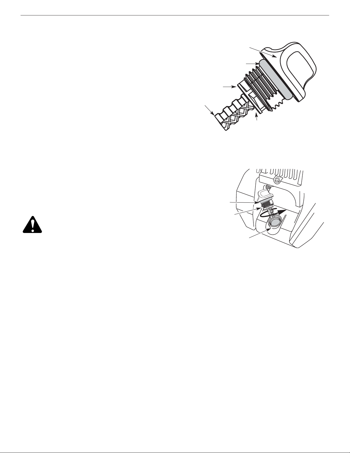
Checking The Oil Level
The importance of checking and maintaining the proper
oil level in the crankcase cannot be overemphasized.
Check oil before each use:
1. Stop the engine and allow oil to drain into the crankcase.
2. Place the unit on a flat, level surface to get a proper
oil level reading.
3. Keep dirt, grass clippings and other debris out of the
engine. Clean the area around the oil fill plug/dipstick
before removing it.
4. Remove the oil fill plug/dipstick and wipe off oil.
Reinsert it all the way back in.
5. Remove the oil fill plug/dipstick and check the oil level.
Oil should be up to the top of the dipstick. See Figure 40.
6. If the level is low, add a small amount of oil to the oil
fill hole and recheck. Repeat this procedure until the
oil level reaches the top of the dipstick.
NOTE: Do not overfill the unit.
Top of Dipstick
O-Ring
Oil Fill Plug/Dipstick
NOTE: Make sure the O-ring is in place on the oil fill
plug/dipstick when checking and changing the
oil. See Figure 41.
Oil Fill Plug/Dipstick
Oil Fill Hole
O-Ring
Full
Add 1.4-1.5 Oz.
(41-44 ml)
CAUTION: To prevent extensive engine
wear and damage to the unit, always
maintain the proper oil level in the
crankcase. Never operate the unit with the
oil level below the bottom of the dipstick.
Figure 40
Figure 41
Installing a Prewound Reel
1. Hold the outer spool with one hand and unscrew the
bump knob clockwise. See Figure 31. Inspect the bolt
inside the bump knob to make sure it moves freely.
Replace the bump knob if damaged.
2. Remove the old inner reel from the outer spool. See
Figure 31.
3. Remove the spring from the old inner reel. See Figure 31.
4. Place the spring in the new inner reel.
NOTE:The spring must be assembled on the inner reel
before reassembling the cutting attachment.
5. Insert the ends of the line through the eyelets in the
outer spool. See Figure 39.
6. Place the new inner reel inside the outer spool. Push the
inner reel and outer spool together. While holding the
inner reel and outer spool, grasp the ends and pull firmly
to release the line from the holding slots in the spool.
7. Hold the inner reel in place and install the bump knob
by turning counterclockwise. Tighten securely.
Replacement Parts
See Accessories / Replacement Parts.
20
SECTION 7: MAINTENANCE AND REPAIR INSTRUCTIONS
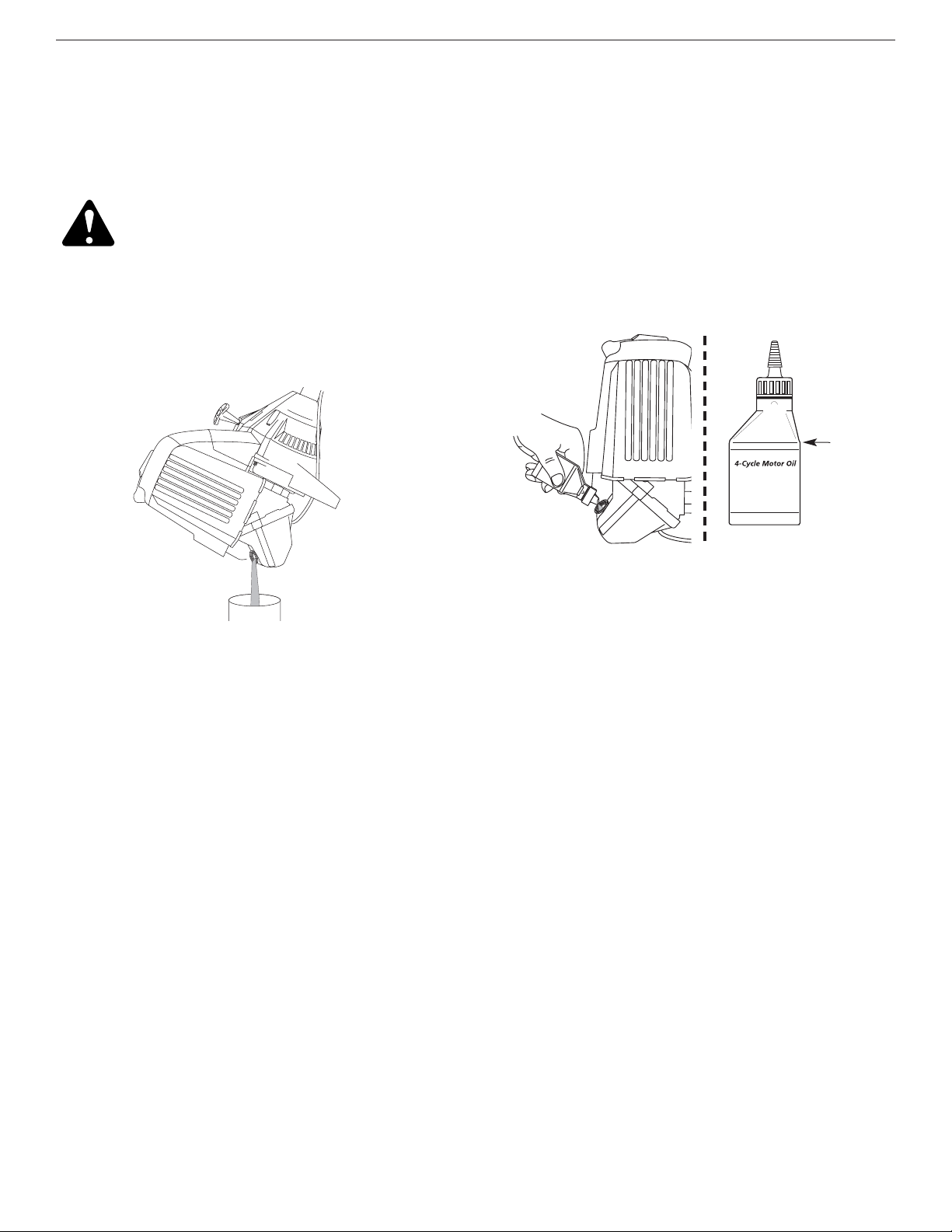
Changing The Oil
For a new engine, change the oil after the first 10 hours of
operation. Change the oil while the engine is still warm. The
oil will flow freely and carry away more impurities.
CAUTION: Wear gloves to prevent injury
when handling the unit.
1. Unplug spark plug boot to prevent accidental starting.
2. Remove the oil fill plug/dipstick.
3. Pour the oil out of the oil fill hole and into a container
by tipping the unit to a vertical position. See
Figure 42. Allow ample time for complete drainage.
6. Replace the oil fill plug/dipstick.
7. Reconnect the spark plug boot.
4. Wipe up any oil residue on the unit and clean up any
oil that may have spilled. Dispose of the oil
according to Federal, State and local regulations.
5. Refill the crankcase with 3.4 fluid ounce (100 ml) of
SAE 30 SF, SG, SH oil.
NOTE: Use the bottle and spout saved from initial use to
measure the correct amount of oil. The top of the
label on the bottle measures approximately 3.4
ounces (100 ml). Check the level with the
dipstick. If the level is low, add a small amount of
oil and recheck. Do not overfill. See Figure 43.
Fill Level
Figure 42
Figure 43
21
SECTION 7: MAINTENANCE AND REPAIR INSTRUCTIONS
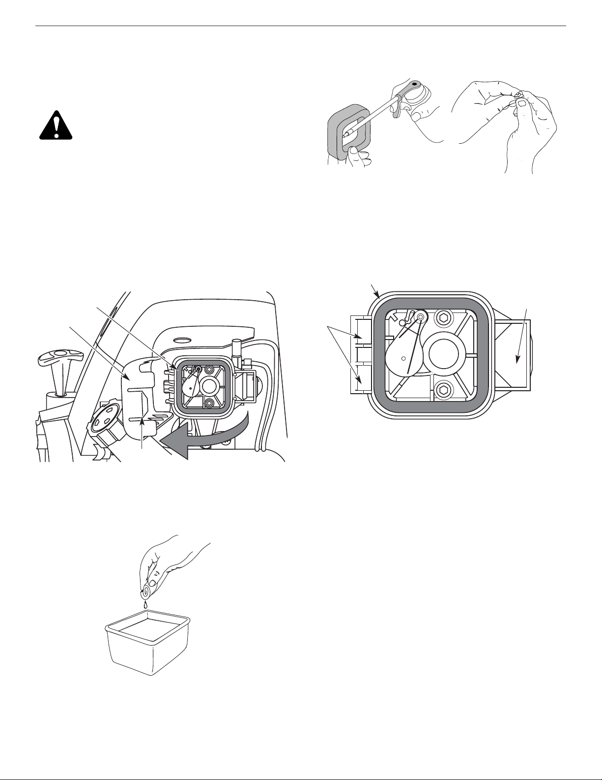
Air Filter Maintenance
Cleaning the Air Filter
Clean and re-oil the air filter every 10 hours of operation.
It is an important item to maintain. Failure to maintain the
air filter will VOID the warranty.
1. Open the air filter cover. Push the tab on the right
side of the cover inward. Then pull the air filter cover
out and to the left. See Figure 44.
NOTE: It may be necessary to remove the fuel cap to
completely remove the air filter cover.
2. Remove the air filter. See Figure 44.
3. Wash the filter in detergent and water. See Figure 45.
Rinse the filter thoroughly and allow it to dry.
4. Apply enough clean SAE 30 motor oil to lightly coat
the filter. See Figure 46.
Air Filter
Air Filter Cover
Tab
5. Squeeze the filter to spread and remove excess oil.
See Figure 47.
Back Plate Slot
Slots
6. Replace the filter. See Figure 48.
NOTE: If the unit is operated without the air filter, you
will VOID the warranty.
7. Reinstall the air filter cover. Position the hooks on
the left side of the air filter cover into the slots at the
left side of the back plate. See Figure 48.
NOTE: It may be necessary to remove the fuel cap to
reinstall the air filter cover.
8. Swing the cover to the right until the tab on the air
filter cover snaps into place in the slot on the back
plate. See Figure 44 and 48.
9. Replace the fuel cap if it was removed.
Back Plate
Carburetor Adjustment
The idle speed of the engine is adjustable through the air
filter/muffler cover. See Figure 49.
NOTE: Careless adjustments can seriously damage your
unit. An authorized service dealer should make
carburetor adjustments.
Check Fuel
Old fuel is usually the reason for improper unit
performance. Drain and refill the tank with fresh fuel prior
to making any adjustments. Refer to Oil and Fuel
Information.
Figure 48
Figure 47
Figure 45
Figure 44
Figure 46
WARNING: To avoid serious personal injury,
always turn your trimmer off and allow it to
cool before you clean or service it.
22
SECTION 7: MAINTENANCE AND REPAIR INSTRUCTIONS
Clean Air Filter
The condition of the air filter is important to the operation
of the unit. A dirty air filter will restrict air flow and change
the air/fuel mixture. This is often mistaken for an out of
adjustment carburetor. Check the condition of the air
filter before adjusting the idle speed screw. Refer to Air
Filter Maintenance.
Adjust Idle Speed
WARNING: The cutting attachment may
spin during idle speed adjustments. Wear
protective clothing and observe all safety
instructions to prevent serious personal
injury.
If, after checking the fuel and cleaning the air filter, the
engine still will not idle, adjust the idle speed screw as
follows:
1. Start the engine and let it run at a high idle for a minute
to warm up. Refer to Starting/Stopping Instructions.
2. Release the throttle trigger and let the engine idle. If the
engine stops, insert a small phillips or flat blade screwdriver
into the hole in the air filter/muffler cover.
See Figure 49.
Turn the idle speed screw in, clockwise, 1/8 of a turn at a
time (as needed) until the engine idles smoothly.
NOTE: The cutting attachment should not rotate when
the engine idles.
3. If the cutting attachment rotates when the engine idles,
turn the idle speed screw counterclockwise 1/8 of a
turn at a time (as needed), to reduce idle speed.
Checking the fuel, cleaning the air filter, and adjusting the
idle speed should solve most engine problems. If not and
all of the following are true:
• the engine will not idle
• the engine hesitates or stalls on acceleration
• there is a loss of engine power
Have the carburetor adjusted by an authorized service dealer.
WARNING: After turning the unit off, make
sure the cutting attachment has stopped
before setting the unit down. This helps
prevent serious personal injury.
Idle Adjustment Screw
Remove Screws
Engine Cover
2. Remove the two (2) screws on top of the engine cover
with a Flat-head or T-25 Torx screwdriver. See Figure 51.
Engine Cover
Muffler
Rocker Arm Clearance
This requires disassembly of the engine. If you feel
unsure or unqualified to perform this, take the unit to an
authorized service center.
NOTE: Inspect the valve to rocker arm clearance with a
feeler gauge after the first 10 hours of operation
and then every 25 hours of operation thereafter.
• The engine must be cold when checking or adjusting
the valve clearance.
• This task should be performed inside, in a clean,
dust free area.
1. Remove the muffler cover by pressing down on it,
separating it from the engine cover. Using a flat
blade screwdriver, disengage the middle and front
tabs and slots first. The cover will hinge off from the
rear tab. See Figure 50.
Top View Of The Engine
Front Slot
Front Tab
Middle Tab
Middle Slot
Rear Slot
and Tab
Figure 49
Figure 51
Figure 50
23
4. Disconnect the spark plug wire.
5. Clean dirt from around the spark plug. Remove the
spark plug from the cylinder head by turning a 5/8 in.
socket counterclockwise.
6. Remove the engine cover. See Figure 51.
7. Clean dirt from around the rocker arm cover.
Remove the screw holding the rocker arm cover with
a large flat blade screwdriver or Torx T-25 bit. See
Figure 53. Remove the rocker arm cover and gasket.
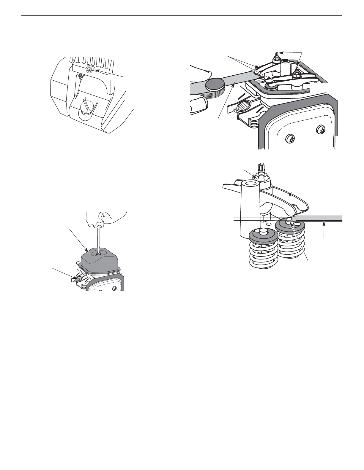
3. Remove the screw behind the engine cover. See
Figure 52.
Rocker Arm Cover
Screw
Spark Plug Hole
8. Pull the starter rope slowly to bring the piston to the top
of its travel, (known as top dead center). Check that:
• The piston is at the top of its travel while looking in
the spark plug hole. See Figure 53.
• Both rocker arms move freely, and both valves are
closed.
If these statements are not true, repeat this step.
9. Slide the feeler gauge between the rocker arm and the
valve return spring. Measure the clearance between the
valve stem and rocker arm. See Figure 54. Measure
both the intake and exhaust valves.
Adjusting Nuts
Feeler Gauge
Rocker Arms
The recommended clearance for both intake and
exhaust is .003 – .006 in. (.076 – 0.152 mm). Use a
standard automotive .005 in. (0.127 mm) feeler gauge.
The feeler gauge should slide between the rocker arm
and valve stem with a slight amount of resistance,
without binding. See Figure 54.
Feeler Gauge
Adjusting Nut
Rocker Arm
.003–.006 in.
(.076–.152 mm)
Valve Stem
10. If the clearance is not within specification:
a. Turn the adjusting nut using a 5/16 inch (8 mm)
wrench or nut driver. See Figure 55.
• To increase clearance, turn the adjusting nut
counterclockwise.
• To decrease clearance, turn the adjusting nut
clockwise.
b. Recheck both clearances, and adjust as necessary.
11. Reinstall the rocker arm cover using a new gasket.
Torque the screw to 20–30 in
•lb (2.2–3.4 N•m).
12. Reinstall the engine cover. Check alignment of the
cover before tightening the screws. Tighten screws.
13. Reinstall the muffler cover. Slip the rear tab on the
muffler cover into the engine cover rear slot. Then
slide the remaining slots into the tabs until they snap
into place. See Figure 50.
14. Check the spark plug and reinstall. See Replacing
the Spark Plug.
15. Replace the spark plug wire.
INTAKE
EXHAUST
SECTION 7: MAINTENANCE AND REPAIR INSTRUCTIONS
Figure 55
Figure 54
Figure 53
Figure 52
24
SECTION 7: MAINTENANCE AND REPAIR INSTRUCTIONS
Replacing the Spark Plug
Use a replacement part number 180852 spark plug (or
equivalent). The correct air gap is 0.025 inch (0.655
mm). Remove the plug after every 25 hours of operation
and check its condition.
1. Stop the engine and allow it to cool. Grasp the plug
wire firmly and pull it from the spark plug.
2. Clean around the spark plug. Remove the spark plug
from the cylinder head by turning a 5/8 in. socket
counterclockwise.
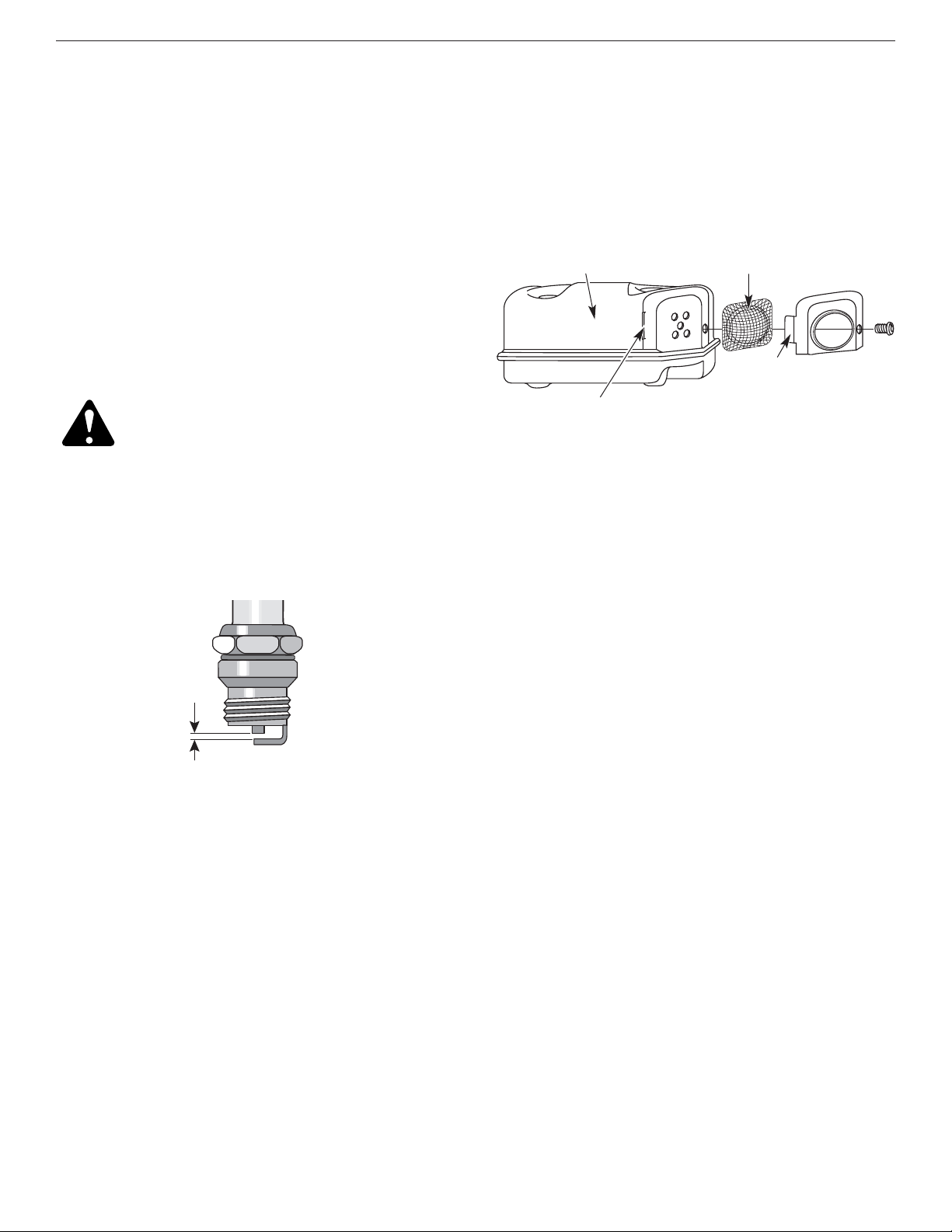
3. Replace cracked, fouled or dirty spark plug. Set the
air gap at 0.025 in. (0.655 mm) using a feeler gauge.
See Figure 56.
CAUTION: Do not sand blast, scrape or
clean electrodes. Grit in the engine could
damage the cylinder.
4. Install a correctly-gapped spark plug in the cylinder
head. Tighten by turning the 5/8 inch socket
clockwise until snug.
If using a torque wrench torque to:
110-120 in.•lb. (12.3-13.5 N•m).
Do not over tighten.
0.025 in.
(0.655 mm)
Figure 56
Muffler
Spark Arrestor Screen
Spark Arrestor Cover
Tab
Slot
Spark Arrestor Maintenance
1. Remove the muffler cover. See Rocker Arm Clearance.
2. With a flat blade screwdriver or Torx T-20 bit,
remove the screw attaching the spark arrestor cover
to the muffler. See Figure 57.
3. Pull the tab on the spark arrestor cover out of the
muffler. Remove the spark arrestor cover.
4. Remove the spark arrestor screen from the spark
arrestor cover.
5. Clean the spark arrestor screen with a wire brush or
replace it.
6. Reinstall the spark arrestor screen, spark arrestor
cover and screw.
Figure 57

25
Accessories/Replacement Parts
4-Cycle Oil . . . . . . . . . . . . . . . . . . . . . . . . . . . . . . .181786
Spark Plug . . . . . . . . . . . . . . . . . . . . . . . . . . . . . . .180852
Spark Arrestor Screen . . . . . . . . . . . . . . . . . . . . . .180890
Replacement Line . . . . . . . . . . . . . . . . . . . . . . . . 180120
Replacement Line Cartridge . . . . . . . . . . . . . . . . 147345
Inner Reel Spring . . . . . . . . . . . . . . . . . . . . . . . . 610636
Outer Spool . . . . . . . . . . . . . . . . . . . . . . . . . . . . . 683301
Inner Reel . . . . . . . . . . . . . . . . . . . . . . . . . . . . . . 147495
Bump Knob . . . . . . . . . . . . . . . . . . . . . . . . . . . . . 180814
Fuel Cap . . . . . . . . . . . . . . . . . . . . . . . . . . . . . .753-1229
Shoulder Harness . . . . . . . . . . . . . . . . . . . . . . . .682075
For specific replacement parts, refer to the parts list
located on the inside back cover of this manual.
3. Allow the engine to cool. Remove the spark plug and
put 1 oz. (30 ml) of any high quality motor oil into the
cylinder. Pull the starter rope slowly to distribute the
oil. Reinstall the spark plug.
NOTE: Remove the spark plug and drain all of the oil
from the cylinder before attempting to start the
trimmer after storage.
4. Thoroughly clean the unit and inspect for any loose
or damaged parts. Repair or replace damaged parts
and tighten loose screws, nuts or bolts. The unit is
ready for storage.
Transporting
• Allow the engine to cool before transporting.
• Secure the unit while transporting.
• Drain fuel from unit.
• Tighten fuel cap before transporting.
Cleaning
WARNING: To avoid serious personal injury,
always turn your trimmer off and allow it to
cool before you clean or service it.
Use a small brush to clean off the outside of the unit. Do
not use strong detergents. Household cleaners that
contain aromatic oils such as pine and lemon, and
solvents such as kerosene, can damage plastic housing
or handle. Wipe off any moisture with a soft cloth.
Storage
• Never store the unit with fuel in the tank where fumes
may reach an open flame or spark.
• Allow the engine to cool before storing.
• Store the unit locked up to prevent unauthorized use
or damage.
• Store the unit in a dry, well-ventilated area.
• Store the unit out of the reach of children.
Long Term Storage
If the unit will be stored for an extended time, use the
following storage procedure:
1. Drain all fuel from the fuel tank into a container. Do
not use fuel that has been stored for more than 60
days. Dispose of the old fuel/oil mix in accordance to
Federal, State, and Local regulations.
2. Start the engine and allow it to run until it stalls. This
ensures that all fuel has been drained from the
carburetor.
SECTION 7: MAINTENANCE AND REPAIR INSTRUCTIONS

26
SECTION 8: TROUBLESHOOTING GUIDE
If further assistance is required, contact your authorized service dealer
Trouble Possible Cause(s) Corrective Action
ENGINE WILL
NOT START
•
On/Off control in the STOP position
• Empty fuel tank
• Primer bulb wasn’t pressed enough
• Engine is flooded
• Old or improperly mixed fuel
• Fouled spark plug
• Plugged spark arrestor
• Turn On/Off control to ON
• Fill fuel tank with fuel
• Press primer bulb fully and slowly 10 times
• Use starting procedure with choke lever in the RUN
position
• Drain gas tank and add fresh fuel
• Replace or clean spark plug
• Clean or replace the spark arrestor
ENGINE WILL
NOT IDLE
• Air filter is plugged
• Old or improperly mixed fuel
• Improper carburetor adjustment
• Replace or clean the air filter
• Drain gas tank and add fresh fuel
• Adjust according to the Carburetor Adjustment section
ENGINE WILL
NOT
ACCELERATE
• Old or improperly mixed fuel
• Improper carburetor adjustment
• Cutting attachment bound with grass
• Dirty air filter
• Plugged spark arrestor
• Drain gas tank and add fresh fuel
• Take to an authorized service dealer for adjustment
• Stop the engine and clean the cutting attachment
• Clean or replace the air filter
• Clean or replace spark arrestor
ENGINE
LACKS
POWER OR
STALLS WHEN
CUTTING
• Old or improperly mixed fuel
• Improper carburetor adjustment
• Fouled spark plug
• Plugged spark arrestor
• Drain gas tank and add fresh fuel
• Take to an authorized service dealer for adjustment
• Replace or clean spark plug
• Clean or replace the spark arrestor
CUTTING
ATTACHMENT
WILL NOT
ADVANCE LINE
• Cutting attachment bound with grass
• Cutting attachment out of line
• Inner reel bound up
• Cutting head is dirty
• Line welded
• Line twisted when refilled
• Not enough line is exposed
• Stop the engine and clean cutting attachment
• Refill with new line
• Replace the inner reel
• Clean inner reel and outer spool
• Disassemble, remove the welded section and rewind
• Disassemble and rewind the line
• Push the bump knob and pull out line until 4 inches
(102 mm) of line is outside of the cutting attachment
CUTTING LINE
ADVANCES
WILDLY
• Oil is in the cutting head • Clean the cutting head attachment

27
SECTION 9: SPECIFICATIONS
Engine Type.......................................................................................................................................... Air-Cooled, 4-Cycle
Displacement......................................................................................................................................... 1.6 cu. in. (26.2 cc)
Operating RPM................................................................................................................................................... 7,200+ rpm
Idle Speed RPM ...................................................................................................................................... 2,800 - 4,000 rpm
Ignition Type.......................................................................................................................................................... Electronic
Ignition Switch............................................................................................................................................... Rocker Switch
Valve clearance...................................................................................................................... .003–.006 in. (.076–.152 mm)
Spark Plug Gap................................................................................................................................ 0.025 inch (0.655 mm)
Lubrication........................................................................................................................................................... SAE 30 Oil
Crankcase Oil Capacity................................................................................................................................ 3.4 oz (100 ml)
Fuel....................................................................................................................................................................... Unleaded
Carburetor....................................................................................................................................... Diaphragm, All-Position
Starter............................................................................................................................................................... Auto Rewind
Muffler..................................................................................................................................................... Baffled with Guard
Throttle............................................................................................................................................... Manual Spring Return
Fuel Tank Capacity......................................................................................................................................... 12 oz (355 ml)
Engine*
Drive Shaft and Cutting Attachment*
*All specifications are based on the latest product information available at the time of printing. We reserve the right to
make changes at any time without notice.
Drive Shaft Housing.................................................................................................................. Aluminum Tube (EZ-Link™)
Throttle Control ........................................................................................................................................ Finger-Tip Trigger
Unit Weight (No Fuel, with J-handle, Cutting attachment shield and Cutting attachment) ........................ 13.15 lbs (6 kg)
Cutting Mechanism................................................................................. 4-Tooth Cutting Blade, Dual String Cutting Head
Line Spool............................................................................................................................................. Bump Line Releaser
Line Spool Diameter............................................................................................................................ 4 inches (101.6 mm)
Trimming Line Diameter.............................................................................................................................. 0.095 (2.41 mm)
Cutting Path Diameter, Cutting Attachment ........................................................................................ 18 inches (45.7 cm)
Cutting Path Diameter, Cutting Blade.................................................................................................... 8 Inches (204 mm)
Shoulder Harness ................................................................................................................................... Single Quick-Snap

28
NOTES

29
EPA Emission Control Warranty Statement
Your Warranty Rights and Obligations
The Environmental Protection Agency and MTD LLC (MTD) are pleased to explain the emission control system warranty
on your 2002 and later small off-road engine. New small off-road engines must be designed, built and equipped to meet
stringent anti-smog standards. Yard Man must warrant the emission control system on your small off-road engine for
the periods of time listed below provided there has been no abuse, neglect or improper maintenance of your small offroad engine.
Your emission control system may include parts such as the carburetor or fuel-injected system, the ignition system, and
catalytic converter. Also included may be hoses, belts, connectors and other emission-related assemblies.
Where a warrantable condition exists, Yard Man will repair your small off-road engine at no cost to you including
diagnosis, parts and labor.
The 2002 and later small off-road engines are warranted for two years. If any emission-related part on your engine is
defective, the part will be repaired or replaced my Yard Man.
Owners Warranty Responsibilities
• As the small off-road engine owner, you are responsible for the performance of the required maintenance listed in your
operator’s manual. Yard Man recommends that you retain all receipts covering maintenance on your small off-road
engine, but Yard Man cannot deny warranty solely for the lack of receipts or for your failure to ensure the performance
of all scheduled maintenance.
• As the small off-road engine owner, you however should be aware that Yard Man may deny you warranty coverage if
your small off-road engine or a part has failed due to abuse, neglect, improper maintenance or unapproved
modifications.
• You are responsible for presenting your small off-road engine to a Yard Man Authorized Service Center as soon as a
problem exists. The warranty repairs should be completed in a reasonable amount of time, not to exceed 30 days.
If you have any questions regarding your warranty rights and responsibilities, you should call 1-800-345-8746.
Manufacturer’s Warranty Coverage
• The warranty period begins on the date the engine or equipment is delivered to the retail purchaser.
• The manufacturer warrants to the initial owner and each subsequent purchaser, that the engine is free from defects in
material and workmanship which cause the failure of a warranted part for a period of two years.
• Repair or replacement of warranted part will be performed at no charge to the owner at an Authorized Yard Man
Service Center. For the nearest location please contact Yard Man at: 1-800-345-8746.
• Any warranted part which is not scheduled for replacement, as required maintenance or which is scheduled for only
for regular inspection to the effect of “Repair or Replace as Necessary” is warranted for the warranty period. Any
warranted part which is scheduled for replacement as required maintenance will be warranted for the period of time up
to the first scheduled replacement point for that part.
• The owner will not be charged for diagnostic labor which leads to the determination that a warranted part is defective,
if the diagnostic work is performed at an Authorized Yard Man Service Center.
• The manufacturer is liable for damages to other engine components caused by the failure of a warranted part still
under warranty.
• Failures caused by abuse, neglect or improper maintenance are not covered under warranty.
• The use of add-on or modified parts can be grounds for disallowing a warranty claim. The manufacturer is not liable to
cover failures of warranted parts caused by the use of add-on or modified parts.
• In order to file a claim, go to your nearest Authorized Yard Man Service Center. Warranty services or repairs will be
provided at all Authorized Yard Man Service Centers.
• Any manufacturer approved replacement part may be used in the performance of any warranty maintenance or repair
of emission related parts and will be provided without charge to the owner. Any replacement part that is equivalent in
performance or durability may be used in non-warranty maintenance or repair and will not reduce the warranty
obligations of the manufacturer
• The following components are included in the emission related warranty of the engine, air filter, carburetor, primer, fuel
lines, fuel pick up/ fuel filter, ignition module, spark plug and muffler.

MANUFACTURER’S LIMITED WARRANTY FOR:
No implied warranty, including any implied warranty of
merchantability or fitness for a particular purpose,
applies after the applicable period of express written
warranty above as to the parts as identified. No other
express warranty or guaranty, whether written or oral,
except as mentioned above, given by any person or
entity, including a dealer or retailer, with respect to any
product shall bind MTD. During the period of the
Warranty, the exclusive remedy is repair or replacement
of the product as set forth above. (Some states do not
allow limitations on how long an implied warranty lasts, so
the above limitation may not apply to you.)
The provisions as set forth in this Warranty provide the
sole and exclusive remedy arising from the sales. MTD
shall not be liable for incidental or consequential loss or
damages including, without limitation, expenses incurred
for substitute or replacement lawn care services, for
transportation or for related expenses, or for rental
expenses to temporarily replace a warranted product.
(Some states do not allow limitations on how long an implied
warranty lasts, so the above limitation may not apply to you.)
In no event shall recovery of any kind be greater than the
amount of the purchase price of the product sold. Alteration
of the safety features of the product shall void this Warranty.
You assume the risk and liability for loss, damage, or injury
to you and your property and/or to others and their property
arising out of the use or misuse or inability to use the
product.
This limited warranty shall not extend to anyone other than
the original purchaser, original lessee or the person for whom
it was purchased as a gift.
How State Law Relates to this Warranty: This warranty
gives you specific legal rights, and you may also have other
rights which vary from state to state.
To locate your nearest service dealer dial 1-800-345-8746
in the United States or 1-800-668-1238 in Canada.
MTD LLC
P.O. Box 361131
Cleveland, OH 44136-0019
The limited warranty set forth below is given by MTD
LLC (“MTD”) with respect to new merchandise purchased and
used in the United States, its possessions and territories.
MTD warrants this product against defects in material and
workmanship for a period of two (2) years commencing on the
date of original purchase and will, at its option, repair or
replace, free of charge, any part found to be defective in
material or workmanship. This limited warranty shall only apply
if this product has been operated and maintained in
accordance with the Operator’s Manual furnished with the
product, and has not been subject to misuse, abuse,
commercial use, neglect, accident, improper maintenance,
alteration, vandalism, theft, fire, water or damage because of
other peril or natural disaster. Damage resulting from the
installation or use of any accessory or attachment not
approved by MTD for use with the product(s) covered by this
manual will void your warranty as to any resulting damage. This
warranty is limited to ninety (90) days from the date of original
retail purchase for any MTD product that is used for rental or
commercial purposes, or any other income-producing purpose.
HOW TO OBTAIN SERVICE: Warranty service is available,
WITH PROOF OF PURCHASE THROUGH YOUR LOCAL
AUTHORIZED SERVICE DEALER. To locate the dealer in your
area, please check for a listing in the Yellow Pages or contact
the Customer Service Department of MTD LLC by calling
1-800-345-8746 or writing to P.O. Box 361131, Cleveland OH
44136-0019 or if in Canada call 1-800-668-1238. No product
returned directly to the factory will be accepted unless prior
written permission has been extended by the Customer
Service Department of MTD LLC.
This limited warranty does not provide coverage in the
following cases:
A. Tune-ups - Spark Plugs, Carburetor Adjustments, Filters.
B. Wear items - Bump Knobs, Outer Spools, Cutting Line,
Inner Reels, Starter Pulley, Starter Ropes, Drive Belts.
C. MTD does not extend any warranty for products sold or
exported outside of the United States of America, its
possessions and territories, except those sold through
MTD’s authorized channels of export distribution.
MTD reserves the right to change or improve the design of
any MTD Product without assuming any obligation to modify
any product previously manufactured.

Manuel de l'utilisateur
IMPORTANT : lisez soigneusement les règles et consignes de sécurité avant de faire fonctionner cet équipement.
Français
Désherbeuse/
débroussailleuse
à gaz à 4-temps
Modèle
YM26BC
IMPRIME AUX ÉTATS-UNIS.
PARTIE NUMÉRO. 769-00576 (12/02)

F2
TABLE DES MATIÈRES
Contenu . . . . . . . . . . . . . . . . . . . . . . . . . . . . . . . . . . . . . . . . . . . . . . . . . . . . . . . . . . Page
Consignes de sécurité . . . . . . . . . . . . . . . . . . . . . . . . . . . . . . . . . . . . . . . . . . . . . . . . . F3
Familiarisez-vous avec la désherbeuse . . . . . . . . . . . . . . . . . . . . . . . . . . . . . . . . . . . . F7
Instructions de montage . . . . . . . . . . . . . . . . . . . . . . . . . . . . . . . . . . . . . . . . . . . . . . . F8
Informations sur l'huile et le carburant . . . . . . . . . . . . . . . . . . . . . . . . . . . . . . . . . . . F11
Instructions de démarrage et d'arrêt . . . . . . . . . . . . . . . . . . . . . . . . . . . . . . . . . . . . . F13
Mode d’emploi . . . . . . . . . . . . . . . . . . . . . . . . . . . . . . . . . . . . . . . . . . . . . . . . . . . . . . F14
Entretien et réparations . . . . . . . . . . . . . . . . . . . . . . . . . . . . . . . . . . . . . . . . . . . . . . . F17
Nettoyage et entreposage . . . . . . . . . . . . . . . . . . . . . . . . . . . . . . . . . . . . . . . . . . . . . F25
Depannage . . . . . . . . . . . . . . . . . . . . . . . . . . . . . . . . . . . . . . . . . . . . . . . . . . . . . . . . . F26
Caracteristiques . . . . . . . . . . . . . . . . . . . . . . . . . . . . . . . . . . . . . . . . . . . . . . . . . . . . . F27
Garantie . . . . . . . . . . . . . . . . . . . . . . . . . . . . . . . . . . . . . . . . . . . . . . . . . . . . . . . . . . . F30
Liste des Pièces . . . . . . . . . . . . . . . . . . . . . . . . . . . . . . . . . . . . . . . . . . . . .Couvercle Arriére
TROUVER LE NUMÉRO DE MODÈLE
Ce manuel de l'utilisateur est un élément important de votre désherbeuse neuve. Il a été conçu pour vous aider à
assembler, préparer et faire l'entretien de l’appareil afin d’assurer des performances optimales. Prenez soin de lire et
comprendre son contenu.
Avant d’assembler votre nouvel équipement, repérez la plaque signalétique de l’appareil et copiez
ses informations dans l’espace fourni à cet effet ci-dessous. Les informations de la plaque signalétique
sont essentielles si vous désirez obtenir de l’aide auprès de notre service technique ou d’un distributeur
agréé.
• Le numéro de modèle se trouve sur la partie infériere du moteur. Un exemple de plaque signalétique est présenté
ci-dessous. Veuillez copier le numéro de modèle et le numéro de série de l’équipement dans l’espace ci-dessous
afin de pouvoir vous y référer ultérieurement.
SERVICE TECHNIQUE
Si vous éprouvez des difficultés à assembler ce produit ou si vous avez des questions concernant les commandes, le
fonctionnement ou l’entretien de cet appareil, veuillez communiquer avec notre service technique.
Appelez le 1- (800)-345-8746, ou le 1- (800)-668-1238 au Canada, pour joindre un de nos représentants.
Veuillez avoir les numéros de modèle et de série de l’appareil à portée de main lorsque vous appelez.
Reportez-vous à la section précédente pour savoir où trouver ces informations. On vous demandera le
numéro de série au moment de traiter votre demande.
VISITEZ NOTRE SITE WEB
Visitez notre site Web à www.yardman.com pour de plus amples informations à propos de nos produits de qualité, de
notre service à la clientèle, des pièces, des trucs et conseils, de la documentation etc.
Copiez le numéro de
modèle et pièce mère ici :
Copiez le numéro de série ici :
S/N :
ITEM :
MODEL :
Numéro de modèle
Numéro de série
Numéro de pièce mère
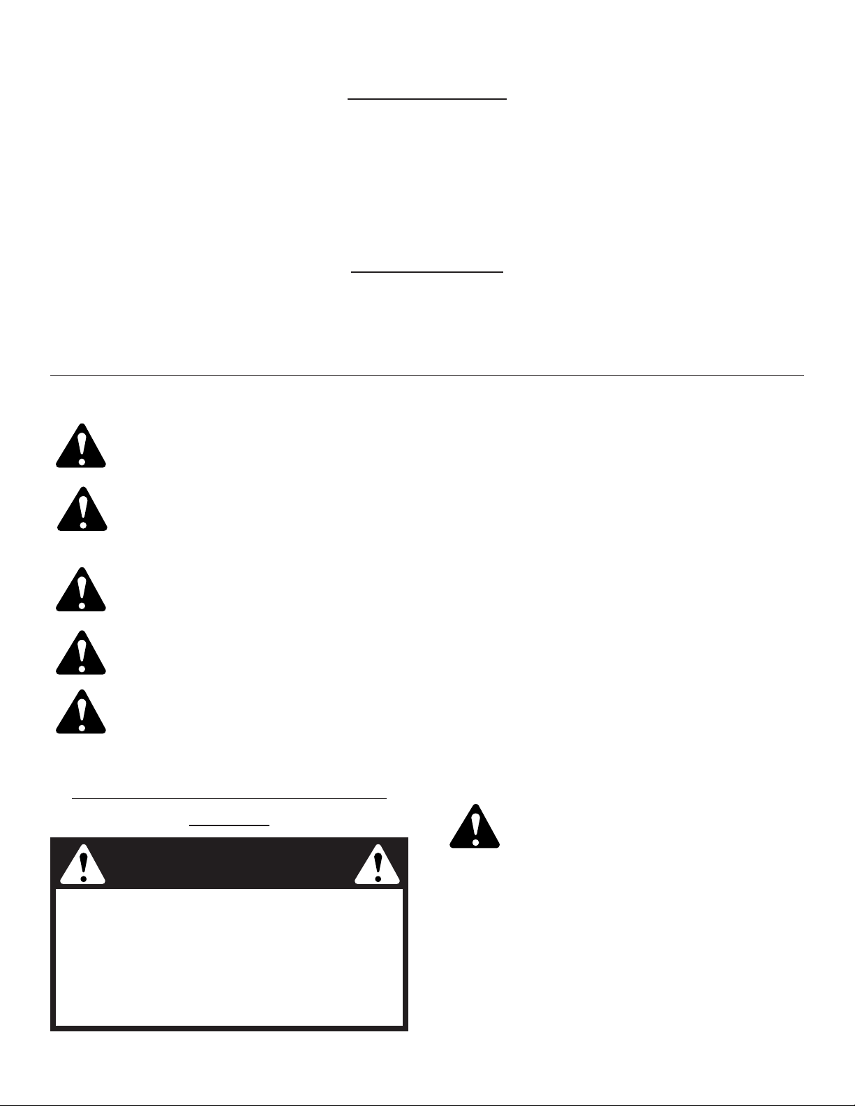
F3
PARE-ÉTINCELLES
REMARQUE :
à l'intention des utilisateurs opérant dans les terres forestières des États-Unis et dans les états
de Californie, du Maine, de l'Orégon et de Washington. Toutes les terres forestières des États-Unis et de l'état de
Californie (Codes sur les ressources publiques 4442 et 4443), de l'Orégon et de Washington exigent de par la loi que
certains moteurs à combustion interne utilisés dans des zones couvertes de taillis ou d'herbe soient équipés d'un pareétincelles en parfait état de fonctionnement, ou qu'ils soient conçus, équipés et entretenus pour la prévention des
incendies. Prenez tous les renseignements nécessaires auprès des autorités de votre province ou de votre municipalité
concernant la réglementation en vigueur. Vous pourriez être passible d'une amende ou être tenu responsable si vous ne
respectez pas cette réglementation. Cet appareil est équipé d'un pare-étincelles en usine. S’il doit être remplacé,
faites installer par votre concessionnaire LOCAL l'accessoire no. 180890 - pare-étincelles.
AVER
TISSEMENT!
Lisez le(s) manuel(s) de l'utilisateur et suivez tous les avertissements et consignes de sécurité. Vous
pourriez à défaut entraîner des blessures graves pour vous ou d'autres personnes.
SI VOUS AVEZ DES QUESTIONS, APPELEZ LE 1-800-345-8746 AUX ÉTATS-UNIS,OU LE 1-800-668-1238 AU CANADA
Les symboles de sécurité attirent votre attention sur des dangers potentiels. Ces symboles et leurs
détails explicatifs doivent être bien lus et compris. Les avertissements de sécurité ne peuvent éviter
les dangers de par eux-mêmes. Les consignes ou mises en garde qu'ils donnent ne remplacent pas
des mesures préventives appropriées contre les accidents.
SYMBOLE ALERTE DE SÉCURITÉ : indique un danger, un avertissement ou une mise en garde.Soyez vigilant
afin d'éviter toute blessure grave. Ce symbole peut être combiné à d'autres symboles ou pictogrammes.
REMARQUE : donne des informations ou des instructions vitales pour le fonctionnement ou l'entretien de l'équipement.
DANGER: le non-respect d’un avertissement entraînera des blessures graves pour les personnes.
Respectez les consignes de sécurité afin de réduire les risques d'incendie, de choc électrique et de
blessures.
AVERTISSEMENT: le non-respect d’un avertissement peut entraîner des blessures graves pour les
personnes. Respectez les consignes de sécurité afin de réduire les risques d'incendie, de choc
électrique et de blessures.
MISE EN GARDE: le non-respect d’un avertissement risque d’entraîner des blessures graves pour les
personnes. Respectez les consignes de sécurité afin de réduire les risques d'incendie, de choc
électrique et de blessures.
SECTION 1 : CONSIGNES DE SÉCURITÉ
LIRE TOUTES LES INSTRUCTIONS
AVERTISSEMENT : suivez soigneusement les
consignes de sécurité lorsque vous utilisez cet
appareil. Dans l'intérêt de votre sécurité et de
celle des personnes à proximité, prenez soin
de lire ces instructions avant de faire
fonctionner la machine. Veuillez garder les
instructions en lieu sûr pour un usage ultérieur.
Avant L'utilisation
• Veuillez lire le manuel de l'utilisateur attentivement.
Familiarisez-vous avec les commandes et l'utilisation
correcte de l’appareil. Sachez comment arrêter
l’appareil et désactiver les commandes rapidement.
• N'utilisez pas l'appareil si vous êtes fatigué, malade ou
sous l'effet de l'alcool, de drogues ou de
médicaments.
• Soyez conscient des risques de blessure à la tête, aux
mains et aux pieds.
Avertissement de la Proposition 65 de
Californie
AVERTISSEMENT
LES GAZ D'ÉCHAPPEMENT DU MOTEUR
DE CET APPAREIL CONTIENNENT DES
PRODUITS CHIMIQUES CONSIDÉRÉS PAR
L'ÉTAT DE CALIFORNIE COMME
POUVANT CAUSER LE CANCER, DES
MALFORMATIONS CONGÉNITALES OU
D'AUTRES EFFETS NOCIFS SUR
L'APPAREIL DE REPRODUCTION.

F4
• Dégagez la zone de coupe avant chaque usage.
Enlevez tous les objets pouvant être projetés ou
happés par l'accessoire de coupe : cailloux, morceaux
de verre, clous, fil ou ficelle. Éloignez enfants,
spectateurs et animaux de la zone de coupe. Tenez-les
à au moins 15 m (50 pi) de là mais sachez que les
spectateurs risquent quand même d'être atteints par
des objets projetés. Les spectateurs doivent porter des
protections oculaires. Arrêtez immédiatement le moteur
et l'accessoire de coupe si quelqu'un s'approche de
vous.
• Appuyez sur la manette des gaz et assurez-vous
qu'elle revient automatiquement en position de ralenti.
Procédez à tous les réglages ou réparations avant
d'utiliser l'appareil.
• Cet appareil n'est pas conçu pour servir de
débroussailleuse. N'utilisez cet appareil avec aucun
type de lame ou d'accessoire de débroussaillage.
Avertissements de Sécurité Concernant les
Désherbeuses À Essence
AVERTISSEMENT : l'essence est extrêmement
inflammable et ses vapeurs peuvent exploser si on y
met le feu. Veuillez prendre les précautions suivantes :
• Ne stockez le carburant que dans des contenants
spécialement conçus et homologués pour le stockage
de ce type de matières.
• Arrêtez toujours le moteur et laissez-le refroidir avant de
remplir le réservoir de carburant. N'enlevez jamais le
bouchon du réservoir et n'ajoutez jamais de carburant
tant que le moteur est chaud. Ne faites jamais
fonctionner l'appareil sans que le bouchon de carburant
soit bien mis. Desserrez lentement le bouchon afin de
réduire la pression du réservoir.
• Évitez de créer une source d'allumage pour le
carburant déversé. Ne démarrez pas le moteur avant
que les vapeurs de carburant ne se soient dissipées.
• Éloignez l'appareil d'au moins 9,1 m (30 pi) de la
source de ravitaillement en carburant avant de
démarrer le moteur. Ne fumez pas et éloignez toute
source d'étincelles ou de flammes vives du lieu de
ravitaillement ou de fonctionnement de l'appareil.
Pendant L’utilisation de L’appareil
•
Évitez de démarrer ou de faire marcher l'appareil à
l'intérieur d'une pièce ou d'un bâtiment fermé. La
respiration de fumées d'échappement peut provoquer la
mort. Ne faites fonctionner cet appareil qu'à l'extérieur
dans un endroit bien aéré.
• Portez des lunettes de sécurité conformes aux normes
ANSI Z87.1 ainsi que des protège-oreilles durant
l'utilisation de l'appareil. Portez un masque facial ou
antipoussières si vous travaillez dans un lieu
poussiéreux.
• Portez des pantalons épais et longs, des bottes, des
gants et une chemise à manches longues. Ne marchez
pas pieds nus et évitez les vêtements lâches, bijoux,
pantalons courts et sandales. Relevez les cheveux audessus des épaules.
• Le protecteur d'accessoire de coupe doit toujours être
en place lors de l'utilisation de l'appareil. Ne faites pas
marcher l'appareil sans que les deux fils soient bien
déployés, en supposant qu'un fil approprié n’ait été
installé. Assurez-vous que le fil ne dépasse pas le
protecteur de sécurité.
•Cet appareil est muni d'un embrayage. L'accessoire de
coupe reste stationnaire lorsque le moteur est au ralenti.
Si ce n'est pas le cas, faites régler l'appareil par un
technicien agréé.
•
Ajustez la poignée en J selon votre taille pour mieux
l'agripper
.
• Avant de démarrer l'appareil, assurez-vous que
l’accessoire de coupe ne touche aucun objet.
• N'utilisez l'appareil qu'en plein jour ou avec un bon
éclairage artificiel.
• Évitez tout démarrage accidentel. Mettez-vous en position
de démarrage chaque fois que vous tirez sur la corde de
démarrage. L'opérateur et l'appareil doivent tous deux
être en position stable à ce moment-là. Voir les
Instructions de démarrage et d'arrêt.
• Servez-vous des outils appropriés. N'utilisez cet outil que
pour son usage prévu.
• Ne vous étirez pas. Tenez-vous toujours bien campé,
en position d'équilibre.
•
Tenez toujours l'appareil des deux mains lorsque vous le
faites marcher. Agrippez fermement les poignées avant et
arrière.
• Gardez les mains, le visage et les pieds éloignés des
pièces mobiles. Ne touchez pas et n'essayez pas
d'arrêter l'accessoire de coupe en rotation.
• Ne touchez pas le moteur, le boîtier d'engrenages ni le
silencieux. Ces pièces deviennent très chaudes à
l'utilisation. Elles restent chaudes brièvement après
l'arrêt.
• Ne faites pas fonctionner le moteur à un régime plus
élevé que nécessaire pour couper, tailler ou faire les
bordures. Ne faites pas tourner le moteur à haut
régime si vous ne vous faites pas de coupe.
•
Arrêtez toujours le moteur lorsque vous suspendez la
coupe ou lorsque vous vous déplacez d'un lieu de travail
vers un autre.
• Les enfants et adolescents de moins de 15 ans ne
doivent pas utiliser l'appareil exceptés les adolescents
assistés d'un adulte.
• Inspectez l'appareil avant utilisation. Remplacez les
pièces endommagées. Regardez s'il y a des fuites de
carburant. Assurez-vous que les fixations sont
solidement en place. Remplacez les pièces de
l'accessoire de coupe qui sont fendillées, ébréchées
ou endommagées. Assurez-vous que l'accessoire de
coupe est correctement installé et solidement fixé.
Assurez-vous que le protecteur d'accessoire de coupe
est correctement fixé et positionné tel que
recommandé. Vous risquez sinon de causer des
blessures à l'opérateur et aux spectateurs, et
d'endommager l'appareil.
• Utilisez uniquement du fil de remplacement Genuine
Factory PartsMCd'origine de 2,41 mm (0,095 po) de
diamètre. N'utilisez jamais de fil, de chaîne ou de
cordon à renfort métallique car ils peuvent se briser et
se transformer en projectiles dangereux.

F5
• Si vous heurtez un corps étranger ou que celui-ci est
happé, arrêtez le moteur immédiatement et vérifiez
que rien n'a été endommagé. Ne faites pas
fonctionner l'appareil avant réparation des dommages.
Ne faites pas marcher l'appareil si les pièces sont
desserrées ou endommagées.
•
Arrêtez et éteignez le moteur dans les cas suivants :
entretien, réparation ou changement d'accessoires ou
autres.
• Utilisez uniquement des pièces de rechange et des
accessoires homologués par le fabricant pour cet
appareil. Vous les trouverez auprès de votre
distributeur agréé. L'utilisation de pièces ou
d’accessoires non homologués peut causer des
blessures graves ou endommager l’appareil et annuler
sa garantie.
• Gardez l'appareil exempt d'accumulation de végétation
ou autres matières. Celles-ci peuvent rester logées entre
l'accessoire de coupe et le protecteur.
• Afin de diminuer les risques d'incendie, remplacez tout
silencieux ou pare-étincelles défectueux et conservez
le moteur et le silencieux exempts d'herbe, de feuilles
et d'accumulation excessive de graisse ou de
carbone.
Pendant L’Utilisation de la Lame de Coupe
• Prenez soin de bien lire et comprendre tous les
avertissements de sécurité avant de faire fonctionner
cet appareil.
• Portez toujours le harnais d'épaule lorsque vous
utilisez la lame à broussailles.
• Maintenez toujours la poignée entre l'opérateur et
l'accessoire de coupe ou la lame.
• Ne coupez jamais si la lame de coupe est à plus de 76
cm (30 po) au-dessus du sol.
• Lorsque la lame pivotante frappe un objet qu'elle ne
peut pas couper, elle donne un coup brusque qui peut
pousser violemment l'opérateur et l'appareil vers
n'importe quelle direction et faire perdre le contrôle de
l'appareil. Ceci peut se produire à l'improviste si la lame
s'accroche, cale ou se coince. Cela est plus susceptible
de se produire dans les endroits où il est difficile de voir
ce que l'on coupe.
• Avec une lame à broussailles, ne coupez rien de plus
épais que 1,3 cm (1/2 po) au risque de provoquer un
recul violent.
• N'essayez pas de toucher ni d'arrêter la lame pendant
qu'elle tourne.
• La lame continue de tourner à vide une fois le moteur
éteint ou la manette des gaz relâchée et peut causer
des blessures graves. Gardez le contrôle jusqu'à ce
qu'elle ait complètement arrêté de tourner.
• Ne faites pas tourner l'appareil à haut régime si vous
ne faites pas de coupe.
• Si vous heurtez un corps étranger ou que celui-ci est
happé, arrêtez le moteur immédiatement et vérifiez
que rien n'a été endommagé. Réparez tout dommage
éventuel avant de poursuivre le travail. N'utilisez pas
l'appareil si la lame est tordue, fendillée ou émoussée.
Jetez toute lame tordue, fendillée ou émoussée.
• N'aiguisez pas la lame de coupe car son extrémité
risquerait de casser à l'usage et causer des blessures
graves. Remplacez-la plutôt.
• Arrêtez le moteur IMMÉDIATEMENT si vous ressentez
une vibration excessive car cela indique un problème.
Vérifiez soigneusement qu'il n'y a ni écrous ni boulons
desserrés, ni aucun dommage avant de continuer.
Réparez ou remplacez les pièces affectées au besoin.
Aprés L'Utilisation
• Nettoyez la lame de coupe avec un nettoyant ménager
pour éliminer toute accumulation de gomme. Lubrifiez
la lame avec de l'huile mécanique contre la rouille.
• Verrouillez et rangez la lame de coupe dans un lieu
approprié pour éviter toute utilisation indésirable ou
des dommages.
Autres Avertissements de Sécurité
•N'entreposez jamais l'appareil rempli de carburant
dans un édifice où les vapeurs peuvent atteindre une
source de flammes vives ou d'étincelles.
• Laissez le moteur se refroidir avant de l'entreposer ou
de le transporter. Attachez bien l'appareil pendant le
transport.
• Rangez l'appareil dans un endroit verrouillé et sec, ou
élevé et sec, hors de portée des enfants, pour éviter
une utilisation indésirable ou un accident.
•Ne trempez et n'arrosez jamais l'appareil avec de l'eau
ou tout autre liquide. Gardez les poignées sèches,
propres et exemptes de débris. Nettoyez après
chaque usage. Voir la section Nettoyage et
Entreposage.
• Conservez ces instructions. Consultez-les souvent et
servez-vous en pour instruire d'autres usagers. Si
vous prêtez l'appareil à quelqu'un, prêtez-lui
également ces instructions.
CONSERVEZ CES INSTRUCTIONS

F6
SECTION 1a: SYMBOLES DE SÉCURITÉ ET INTERNATIONAUX
Ce manuel de l'utilisateur décrit les symboles et pictogrammes de sécurité et internationaux pouvant apparaître sur ce
produit. Consultez le manuel de l'utilisateur pour les informations concernant la sécurité, le montage, le fonctionnement,
l'entretien et les réparations.
SYMBOLE SIGNIFICATION
• COMMANDE MARCHE/ARRÊT
STOP
ALLUMAGE / DÉMARRAGE / MARCHE
• COMMANDE MARCHE/ARRÊT
STOP
ARRÊT ou STOP
•AVERTISSEMENT SURFACE
CHAUDE
Ne touchez pas un silencieux ou un
cylindre chaud. Vous pourriez vous
brûler. Ces pièces deviennent très
chaudes à l'utilisation. Elles restes
chaudes brièvement après l'arrêt.
• LAME AIGUISÉE
AVERTISSEMENT: le protecteur
d'accessoire de coupe comporte une
lame aiguisée. Ne touchez pas la lame
pour éviter des blessures graves.
• DÉBROUISSAILLEUSES :
remplacez la lame émoussée.
N'aiguisez pas la lame de coupe car son
extrémité risquerait de casser à
l'usage et causer des blessures graves
.
•DÉSHERBEUSE/
DÉBROUISSAILLEUSE SÉCURITÉ
AVERTISSEMENT : les objets projetés et
la tête coupante rotative peuvent causer
des blessures graves. Éloignez les
spectateurs, les enfants et les animaux
domestiques en particulier, d'au moins 15
m (50 pieds) de la zone de coupe. Vous
devez utiliser le protecteur d'accessoire de
coupe lorsque vous vous servez de
l'accessoire de coupe de la
désherbeuse.
• CONTRÔLE DE
L'ÉTRANGLEUR
A. Position d’ÉTRANGLEMENT
MAXIMUM
B.
Position d’ÉTRANGLEMENT
PARTIEL
C. Position MARCHE.
SYMBOLE SIGNIFICATION
• SYMBOLE ALERTE DE
SÉCURITÉ
Indique un danger, un avertissement
ou une mise en garde. Ce symbole
peut être combiné à d'autres symboles
ou pictogrammes.
•AVERTISSEMENT - LISEZ LE
MANUEL DE L'UTILISATEUR
Lisez le manuel de l'utilisateur et suivez
tous les avertissements et consignes
de sécurité. Vous pourriez à défaut
entraîner des blessures graves pour
vous ou d'autres personnes.
• PORTEZ DES PROTECTIONS
(YEUX ET OREILLES)
AVERTISSEMENT: les objets projetés
et les bruits forts peuvent endommager
la vue et l’ouïe. Portez une visière de
norme ANSI Z87.1-1989 et des
protège-oreilles pendant l'utilisation.
• ÉLOIGNEZ LES SPECTATEURS
AVERTISSEMENT: éloignez tout
spectateur, les enfants et les animaux
domestiques en particulier, d'au moins
15 m (50 pi) de la zone de coupe.
• CARBURANT SANS PLOMB
Utilisez toujours du carburant sans
plomb frais et propre.
• NIVEAU D'HUILE
Voir le manuel de l'utilisateur pour le
type d'huile approprié.
•
LES OBJETS PROJETÉS ET LA
TÊTE ROT ATIVE PEUVENT CAUSER
DES BLESSURES GRAVES
AVERTISSEMENT: ne faites pas
fonctionner sans protecteur de sécurité
en plastique. Tenez-vous à l'écart de
l'accessoire de coupe rotatif.
• POIRE D'AMORÇAGE
Enfoncez la poire d'amorçage
complètement et lentement de 10 fois.

F7
SECTION 2 : FAMILIARISEZ-VOUS AVEC LA DÉSHERBEUSE
Poire d'amorçage
Levier d'étrangleur
Bouchon de remplissage / jauge d'huile
Couvercle du
filtre à air
Bougie
Pattes du moteur
Protecteur
d'accessoire
de coupe
Bouchon du
carburant
Manette
des gaz
Lame coupante
Accessoire de coupe
Prise de l'arbre
Bougie
Commande Marche/Arrêt Stop
Corps de l'arbre
Poignée de la
corde de
démarrage
APPLICATIONS
Utilisation comme désherbeuse :
• Coupe d'herbe et de mauvaises herbes légères.
• Coupe de bordures
• Tailler autour des arbres, des clôtures, etc.
Utilisation comme débroussailleuse :
• Coupe de mauvaises herbes et broussailles légères
de pas plus de 1,3 cm (1/2") de diamètre.
D'autres accessoires peuvent être utilisés avec le
YM26BC. Voir la liste d'accessoires.
Silencieux
Pare-Étincelles
Protection du
silencieux
Déverrouilleur
de manette
des gaz
EZ-Link™
Protecteur de
lame / Matériel
de montage du
protecteur
Lame à
broussailles avec
couvercle
Boîtier
d'engrenages
Raccord de soutien
Poignée en J

F8
6. Tenez l'appareil en position d’utilisation (Fig. 3), puis
positionnez la poignée en J de manière à assurer une
prise idéale.
2.
Maintenez les trois pièces ensemble et introduisez les
quatre (4) vis dans les brides supérieure et médiane.
REMARQUE: les trous des brides supérieure et médiane
ne sont alignés que si l’assemblage est correct.
3. Placez les brides et la poignée en J sur le corps de
l'arbre et sur la bride inférieure.
4. Tenez d’un doigt chaque écrou hex dans le
renfoncement de la bride inférieure. Commencez à
visser à l’aide d’un grand tournevis à embout
cruciforme. Ne serrez pas avant de régler le guidon.
5. Glissez la poignée en J en un mouvement de va-etvient jusqu'à ce que la flèche/ligne blanche de
l'autocollant touche la bride (Fig. 2).
Figure 2
SECTION 3: INSTRUCTIONS DE MONTAGE
Figure 1
INST ALLA TION ET RÉGLAGE DE LA POIGNÉE EN J
1. Placez la poignée en J entre les brides supérieure et
médiane (Fig. 1).
Autocollant
7. Serrez les vis des brides uniformément jusqu'à bien
fixer la poignée.
Figure 3
(4) vis
Bride supérieure
Poignée
en J
Bride médiane
Bride inférieure
Écrous
INSTALLER LE HARNAIS
1. Faites passer la bandoulière au centre de la boucle.
2. Tirez la bandoulière par-dessus la traverse et à
travers la fente de la boucle (Fig. 4).
3. Passez le harnais par-dessus la tête puis sur l'épaule.
Accrochez-le au raccord de soutien (Fig. 5).
4. Réglez la longueur en fonction de la taille de
l'opérateur. Tirez la languette pour rallonger ou tirez
la bande pour raccourcir (Fig. 6).
Raccord de soutien
RETRAIT ET INSTALLATION DU PROTECTEUR
D'ACCESSOIRE DE COUPE
Enlevez le protecteur d'accessoire de coupe lorsque
vous vous servez de l'appareil comme débroussailleuse.
Retirez le protecteur d'accessoire de coupe de son support
en enlevant les trois vis à l'aide d'un tournevis à tête plate
(Fig. 7). Rangez les pièces pour un usage ultérieur.
Figure 5
AVERTISSEMENT : n'installez PAS le protecteur
d'accessoire de coupe si vous utilisez l'appareil
avec une lame. Enlevez le protecteur avant
d'enlever ou d'installer la lame.
AVERTISSEMENT : portez toujours le harnais
d'épaule lorsque vous utilisez la lame de
coupe afin d'éviter de vous blesser.
Figure 6
Figure 4

F9
Installez le protecteur d'accessoire de coupe lorsque
vous vous servez de l'appareil comme désherbeuse
Installez le protecteur d'accessoire de coupe sur son
support en insérant les trois vis dans le support. Serrez
fermement avec un tournevis à tête plate (Fig. 7).
RETIRER L’ACCESSOIRE DE COUPE ET INSTALLER
LA LAME DE COUPE
REMARQUE : pour faciliter le retrait ou l'installation de la
lame ou de l'accessoire de coupe, placez
l'appareil au sol ou sur un établi.
Retrait du protecteur d'accessoire de coupe
Voir Retrait et installation du protecteur d'accessoire de coupe.
Retirer l'accessoire de coupe
1. Alignez le trou de la bague de l'arbre avec la fente de
la tige de blocage, puis insérez la tige dans le trou de
la bague (Fig. 8).
(3) vis
Protecteur
d'accessoire de
coupe
Support du
protecteur
Boîtier d'engrenages
Bague de l'arbre
de sortie
Tige de
blocage
Arbre de sortie
Fente de la tige
de blocage
Trou de la bague de l'arbre
2. Maintenez la tige de blocage en place en la
saisissant près du bras de l’appareil (Fig. 9).
3. Tout en tenant la tige de blocage, retirez l’accessoire
de coupe de l’arbre de sortie en le tournant à droite
(Fig. 10). Rangez l’accessoire de coupe pour un
usage ultérieur.
REMARQUE : la retenue de la lame sous l’accessoire de
coupe servira au moment de l’installation de la
lame de coupe.
Accessoire de coupe
Fente de la
tige de
blocage
Tige de
blocage
Support du
protecteur
Tige de
blocage
Lame de
coupe
Retenue de la lame
Écrou
Bague de l'arbre
de sortie
Trou de
guidage
Installer la lame de coupe
4. Placez la lame de coupe sur la bague de l'arbre de
sortie (Fig. 11).
AVERTISSEMENT
: pour éviter des blessures
graves, le protecteur d'accessoire de coupe
DOIT toujours être installé lorsque vous vous
servez de l'appareil comme désherbeuse
.
AVERTISSEMENT : fle boîtier d'engrenages
chauffe à l'usage et peut blesser
l'opérateur. Il reste chaud brièvement
après l'arrêt. Ne le touchez pas tant qu'il
n'a pas refroidi.
AVERTISSEMENT :
pour éviter des blessures
graves, portez toujours des gants lorsque
vous manipulez ou installez la lame
.
Figure 10
Figure 9
Figure 8
Figure 7
Figure 11
SECTION 3: INSTRUCTIONS DE MONTAGE

F10
Pas de guidage
5. Assurez-vous que la lame de coupe est centrée sur le
pas de guidage et qu'elle repose à plat contre la
bague de l'arbre de sortie (Fig. 12).
6. Alignez le trou de la bague de l'arbre avec la fente de
la tige de blocage, puis insérez la tige dans le trou
(Fig. 8).
7. Placez la retenue et l'écrou de la lame sur l'arbre de
sortie. Assurez-vous que la lame est bien mise.
8. Vissez l’écrou vers la gauche contre la lame tout en
tenant la tige de blocage :
• Si vous utilisez une clé dynamométrique et une douille
de 5/8 po, vissez selon les valeurs de couple suivantes:
325 - 335 po•lb, 27 - 28 pi•lb, 37 -38 N•m.
• Si vous n’avez pas de clé dynamométrique, utilisez
une clé fermée ou à douille de 5/8 po et tournez
l'écrou jusqu'à ce que la retenue soit bien ajustée
contre la bague de l'arbre. Assurez-vous que la lame
est bien mise, puis donnez à l'écrou entre 1/4 et 1/2
tour supplémentaire à gauche (Fig. 13).
9. Retirez la tige de blocage de sa fente.
De 1/4 à 1/2 tour
à gauche
RETIRER LA LAME DE COUPE ET INSTALLER
L'ACCESSOIRE DE COUPE
Retirer la lame de coupe
1. Alignez le trou de la bague de l'arbre avec la fente de
la tige de blocage, puis insérez la tige dans le trou.
2. Maintenez la tige de blocage en place en la
saisissant près du bras de l’appareil (Fig. 14).
3. Tenez la tige de blocage et desserrez l'écrou de la
lame en le tournant à droite avec une clé fermée ou à
douille de 5/8 pouce (Fig. 14).
4. Retirez l'écrou, la retenue de lame et la lame. Rangez
l’écrou et la lame ensemble en lieu sûr pour un
usage ultérieur. Gardez hors de portée des enfants.
Installer l'accessoire de coupe
5.
Alignez le trou de la bague de l'arbre avec la fente de la
tige de blocage, puis insérez la tige dans le trou. (Fig. 8).
Placez la retenue de lame sur l’arbre de sortie, la partie
plate reposant contre la bague de l’arbre tel qu'indiqué
sur la Fig. 15. Vissez l'accessoire de coupe à gauche sur
l'arbre. Vissez bien.
REMARQUE : la retenue de la lame doit être installée sur
l'arbre de sortie dans la position indiquée pour
que l’accessoire de coupe fonctionne
correctement.
6. Retirez la tige de blocage.
7. Installez le protecteur d'accessoire de coupe. Voir Retrait
et installation du protecteur d'accessoire de coupe.
À droite
Accessoire de coupe
Tige de
blocage
Retenue de la lame
Bague de l'arbre
de sortie
SECTION 3: INSTRUCTIONS DE MONTAGE
AVERTISSEMENT : pour éviter des
blessures graves et ne pas endommager
l'appareil, ne le faites pas marcher avec la
tige de blocage dans sa fente.
AVERTISSEMENT : n'aiguisez pas la lame
de coupe : son extrémité pourrait casser à
l'usage et causer des blessures graves.
Remplacez-la plutôt.
AVERTISSEMENT
: si la lame de coupe est
décentrée, l'appareil vibrera et la lame
pourrait s'envoler, ce qui causerait des
blessures graves.
AVERTISSEMENT : pour éviter des blessures
graves, le protecteur d'accessoire de coupe
DOIT toujours être installé lorsque vous vous
servez de l'appareil comme désherbeuse.
AVERTISSEMENT : pour éviter des blessures
graves, portez toujours des gants lorsque
vous manipulez ou installez la lam
e.
Figure 14
Figure 15
Figure 12
Figure 13

F11
SECTION 4 : INFORMATIONS SUR L’HUILE ET LE CARBURANT
DANGER: LE REMPLISSAGE EXCESSIF DU
CARTER-MOTEUR PEUT ANTRAÎNER DES
BLESSURES GRAVES. Nous ne saurions
trop insister sur l'importance de la
vérification du niveau d'huile du cartermoteur et de son maintien. Vérifiez l'huile
avant chaque utilisation et changez-la au
besoin tel qu'indiqué dans la section
Changment d'Huile.
TYPE D'HUILE RECOMMANDÉ
Il est extrêmement important d'utiliser les bons type et
indice d'huile dans le carter-moteur. Vérifiez l'huile avant
chaque utilisation et changez-la périodiquement. Le fait
de ne pas utiliser la bonne huile ou d'utiliser une huile
sale peut entraîner une usure et une défaillance
prématurées du moteur.
Utilisez une huile de haute qualité à indice SAE 30 API
(American Petroleum Institute) de type SG, SF, SH.
AJOUT D'HUILE AU CAR TER:MISE EN SERVICE
REMARQUE: cet appareil est livré sans huile. Pour
éviter d’endommager l’appareil, mettez de l’huile
dans le carter moteur avant le démarrage.
Votre appareil est livré avec une bouteille d'huile SAE 30
SF, SG, SH de 100 ml (3,4 oz) (Fig. 16).
REMARQUE : conservez la bouteille pour mesurer
correctement la quantité nécessaire d’huile plus
tard. Voir Changement d'huile.
1. Dévisser le bouchon de la bouteille d’huile et retirez
le papier couvrant l’ouverture. Replacez le bouchon.
Coupez la pointe de la buse de l’entonnoir (Fig. 16).
REMARQUE: n’ajoutez jamais d'huile au carburant ni
au réservoir de carburant.
5. Essuyez toute trace d'huile déversée et replacez le
bouchon de remplissage / la jauge.
Nous ne saurions trop insister sur l'importance de la
vérification du niveau d'huile du carter-moteur et de son
maintien. Vérifiez l'huile avant chaque utilisation et
changez-la au besoin tel qu'indiqué dans la section
Changment d'Huile.
2. Placez l'appareil sur une surface horizontale plane.
3. Retirez le bouchon / la jauge d'huile du cartermoteur. Versez tout le contenu de la bouteille d'huile
dans le carter-moteur (Fig. 17).
4. Versez tout le contenu de la bouteille d'huile dans le
carter-moteur (Fig. 18).
Bouchon de remplissage
/ jauge d'huile
Orifice de remplissage d’huile
Buse d'entonnoir
Joint torique
Orifice de remplissage d’huile
Figure 16
Figure 18
Figure 17
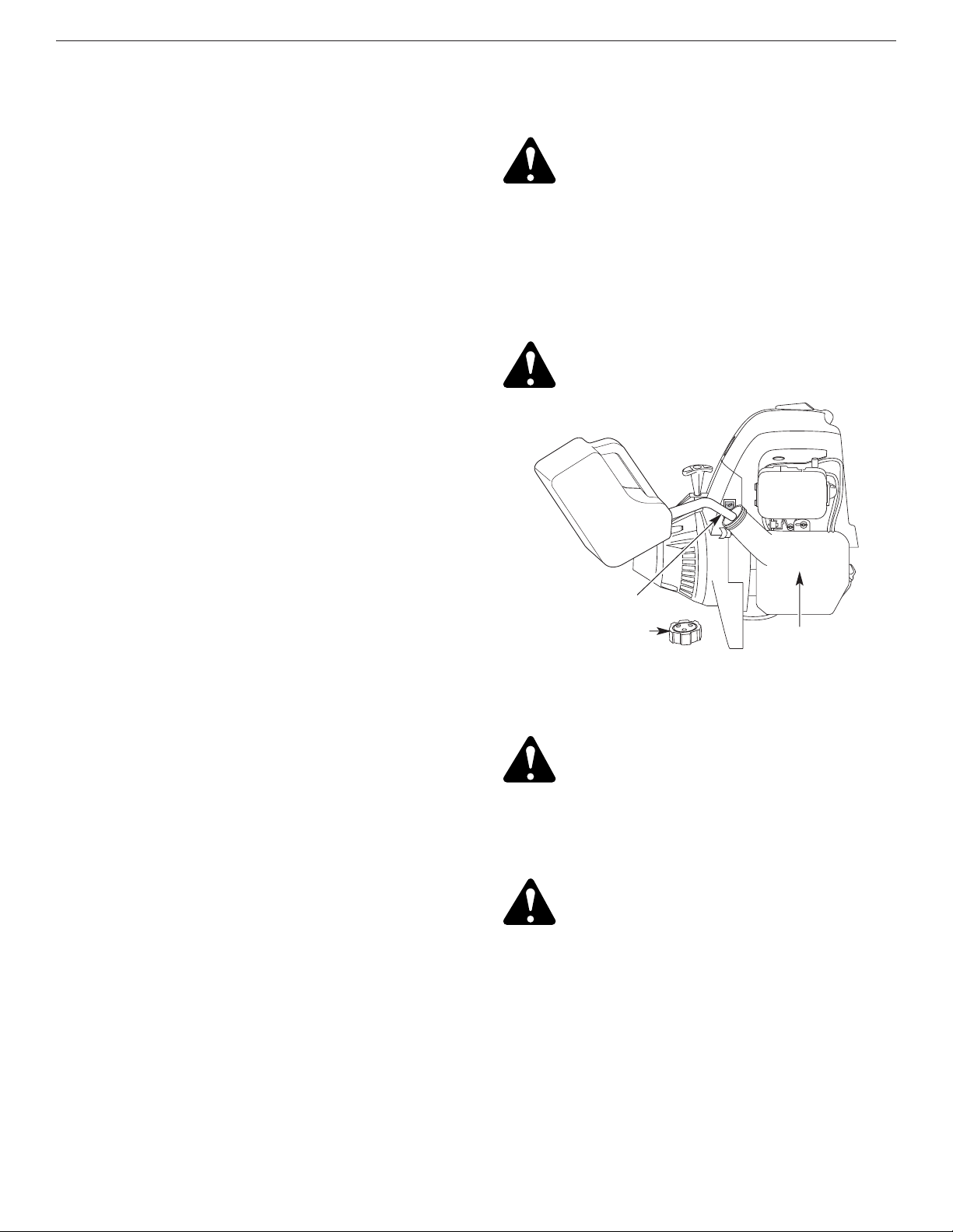
F12
SECTION 4 : INFORMATIONS SUR L’HUILE ET LE CARBURANT
2. Placez le bec du récipient d’essence dans l’orifice du
réservoir (Fig. 19) et remplissez celui-ci.
NOTE : Ne remplissez pas trop le réservoir.
3. Essuyez tout déversement d’essence.
4. Remettez le bouchon du réservoir.
5. Éloignez l'appareil d'au moins 9,1 m (30 pi) de la
source et du site de ravitaillement en carburant avant
de démarrer le moteur.
REMARQUE : Éliminez le vieux carburant
conformément aux règlements fédéral, provincial
et municipal en vigueur.
AJOUT DE CARBURANT
1. Déposez le bouchon à essence (Fig. 19).
INSTRUCTIONS SUR LE MÉLANGE D'HUILE ET DE
CARBURANT
En général, si l'appareil ne fonctionne pas correctement,
c'est que le carburant est vieux ou mal mélangé. Prenez
soin d'utiliser du carburant sans plomb frais et propre.
REMARQUE : ceci est un moteur à quatre temps. Pour
éviter d’endommager l’appareil, ne mélangez
pas l’huile avec l’essence.
Définition des carburants mélangés
Les carburants d'aujourd'hui sont souvent un mélange
d'essence et d'oxygénés comme l'éthanol, le méthanol ou
l'éther MTBE. Un carburant mélangé à l'alcool absorbe
l'eau. Il suffit de 1% d'eau pour séparer le carburant et
l'huile, ce qui forme de l'acide pendant l'entreposage. Si
vous devez utiliser ce type de carburant, servez-vous de
carburant frais (moins de 60 jours).
Usage de carburants mélangés
Si vous choisissez d'utiliser ou ne pouvez éviter d'utiliser
un carburant mélangé, suivez les conseils suivants :
• Utilisez toujours un mélange de carburant frais selon le
manuel de l'utilisateur.
• Utilisez l'additif STA-BILMDou un produit équivalent.
• Agitez toujours le mélange de carburant avant
d'alimenter l'appareil.
• Videz le réservoir et faites marcher le moteur jusqu'à
ce qu'il soit à sec avant d'entreposer l'appareil.
Utilisation d’additifs de carburant
L'utilisation d'additifs de carburant tel que le stabilisant
d’essence STA-BILMDou un produit équivalent permet
d'empêcher la corrosion et de minimiser la formation de
résidus de gomme. L'usage d'additifs peut empêcher le
carburant de former des dépôts nocifs dans le
carburateur pendant six (6) mois maximum. Ajoutez 23
ml (0,8 oz) d'additif par 4 litres (1 gallon) de carburant
selon les instructions du récipient. N'ajoutez JAMAIS
d'additifs directement dans le réservoir de l'appareil.
Carburant
sans plomb
Bouchon du carburant
Réservoir
Bec du récipient
d'essence
Figure 19
AVERTISSEMENT : L'essence est
extrêmement inflammable et les vapeurs qui
s'en dégagent peuvent exploser si on y met le
feu. Pour éviter des blessures graves, arrêtez
le moteur et laissez-le refroidir avant de
remplir le réservoir de carburant. Ne fumez
pas en remplissant le réservoir. Éloignez
toute source d'étincelles ou de flammes vives
du lieu de travail.
AVERTISSEMENT :
Enlevez le bouchon du
réservoir lentement pour ne pas être blessé
par les jets d'essence.
AVERTISSEMENT : Ajoutez de l’essence
dans un lieu propre, bien aéré en plein air.
Évitez de mettre le feu au carburant déversé.
AVERTISSEMENT : Ne faites jamais
marcher l'appareil sans que le bouchon
soit bien mis.

F13
SECTION 5: INSTRUCTIONS DE DÉMARRAGE ET ARRÊT
INSTRUCTIONS DE DÉMARRAGE
Démarrage à froid:Premier démarrage de la journée ou
Moteur à sec
AVERTISSEMENT : faites marcher
l’appareil dans un lieu extérieur bien aéré
uniquement. Les fumées d'échappement
d'oxyde de carbone peuvent être fatales
dans un lieu confiné.
1. Vérifiez le niveau d'huile dans le carter moteur. Voir
Vérification du niveau d'huile.
2. Remplissez le réservoir d’essence sans plomb propre
et frais.
3. Mettez la commande de Démarrage / Arrêt en
position de DÉMARRAGE [I] (Fig. 20).
INSTRUCTIONS D'ARRÊT
1. Relâchez la manette des gaz (Fig. 22). Laissez le
moteur se refroidir au ralenti.
2. Mettez la commande Marche/Arrêt Stop en position
ARRÊT (O) (Fig. 20).
AVERTISSEMENT : évitez tout démarrage
accidentel. Tenez-vous en position de
démarrage lorsque vous tirez la corde de
démarrage (Fig. 22). L'opérateur et
l'appareil doivent tous deux être en position
stable pour éviter des blessures graves.
4. Mettez le levier d'étrangleur en position
d'étranglement MAXIMUM (A) (Fig. 21).
NOTE : Placez le levier d'étrangleur au-dessus du
symbole correspondant de l’autocollant du
couvercle du filtre à air (Fig. 21).
5. Enfoncez complètement puis relâchez graduellement
la poire d'amorçage 10 fois. Vous devriez sentir et
voir de l’essence dans la poire (Fig. 21). S’il n’y en a
pas, appuyez trois fois de plus ou jusqu’à en voir.
9. Tirez sur la corde 1 à 3 fois jusqu’à ce que le moteur
démarre. Laissez-le tourner pendant 15 à 30 secondes.
Si le moteur ne démarre pas, retournez à l’étape 4.
10. Mettez le levier en position de MARCHE (C) et
laissez tourner à pleins gaz pendant 30 secondes.
11. Mettez la manette des gaz en position de ralenti et
commencez le travail.
NOTE : Si le moteur ne démarre pas avec ces
procédures, répétez les étapes 4 à 11 en tirant
DEUX (2) fois en position d'étranglement
MAXIMUM (A)
Redémarrage:Moteur chaud avec carburant
1. Mettez la commande de Démarrage / Arrêt en
position de DÉMARRAGE [I] (Fig. 20).
2. Mettez le levier d'étrangleur en position PARTIEL (B)
(Fig. 21).
3. Enfoncez complètement puis relâchez graduellement
la poire d'amorçage 10 fois. Vous devriez sentir et
voir de l’essence dans la poire (Fig. 21). S’il n’y en a
pas, appuyez trois fois de plus ou jusqu’à en voir.
4. Appuyez sur la manette des gaz pour la mettre à
pleins gaz.
5. L’appareil étant en position de démarrage (Fig. 22),
tirez brusquement sur la corde jusqu’à ce que le
moteur démarre.
6. Après le démarrage du moteur, mettez le levier en
position MARCHE (C) et laissez tourner à pleins
gaz pendant 30 secondes.
NOTE : Si le moteur ne démarre pas avec ces
procédures de redémarrage, employez les
procédures de démarrage de moteur à froid.
6. Appuyez sur la manette des gaz pour la mettre à
pleins gaz.
7. L’appareil étant prêt à démarrer et le levier en position
d'étranglement MAXIMUM (A) tirez brusquement
sur la corde de démarrage 5 fois. Si le moteur essaie de
démarrer avant la cinquième fois, passez à l’étape 8.
8. Mettez le levier d'étrangleur en position PARTIEL (B)
(Fig. 21).
NOTE : Le moteur ne peut fonctionner en position
d'étranglement MAXIMUM (A) .
Poire
d'amorçage
Levier
d'étrangleur
Corde de
démarrage
Manette des gaz
Figure 21
Figure 22
Figure 20
Démarrage/Allumage (I)
Stop/Arrêt (O)
Déverrouilleur de
manette des gaz
Manette des gaz

F14
SECTION 6: MODE D’EMPLO
FONCTIONNEMENT DU EZ-Link
MC
Le système EZ-LinkMCpermet d'utiliser ces accessoires
optionnels :
Souffleuse/aspirateur . . . . . . . . . . . . . . . . . . . . . BV720r
Cultivateur . . . . . . . . . . . . . . . . . . . . . . . . . . . . . GC720r
Coupe-bordure . . . . . . . . . . . . . . . . . . . . . . . . . . LE720r
Taille-haies . . . . . . . . . . . . . . . . . . . . . . . . . . . . . HS720r
Souffleuse (à neige) . . . . . . . . . . . . . . . . . . . . . . . ST720r
Désherbeuse à arbre droit . . . . . . . . . . . . . . . . . SS725r
Élagueuse . . . . . . . . . . . . . . . . . . . . . . . . . . . . . . TP720r
Turbosouffleuse . . . . . . . . . . . . . . . . . . . . . . . . . . TB720r
Retrait de l'accessoire de coupe ou autre
1. Dévissez le bouton vers la gauche (Fig. 23).
2. Appuyez sur le bouton de déclenchement et
maintenez-le enfoncé (Fig. 23).
3. Tenez fermement le corps de l'arbre supérieur et
retirez l'accessoire de coupe ou autre du coupleur
EZ-LinkMC.
Installation de l'accessoire de coupe ou autre
REMARQUE : pour faciliter l'installation ou le retrait
d'accessoires, placez l'appareil au sol ou sur un
établi.
1. Dévissez le bouton vers la gauche (Fig. 23).
2. Tenez fermement l'accessoire et enfoncez-le tout
droit dans le coupleur EZ-LinkMC(Fig. 24).
REMARQUE : aligner le bouton de déclenchement avec le
renfoncement-guide facilitera l'installation (Fig. 23).
3. Serrez le bouton en le tournant à droite (Fig. 24).
Coupleur EZ-Link
MC
Bouton de déclenchement
Renfonce-
ment-guide
Bouton
Trou principal
Corps de l'arbre
supérieur
Corps de l'arbre
inférieur
Bouton de déclenchement
Trou de coupe de
bordures de 90°
Trou de coupe
de bordures
de 180°
Bouton
Pour couper les bordures à l’aide de la tête d'accessoire
de coupe sur les modèle EZ-LinkMC, verrouillez le bouton
de déclenchement de l'accessoire de coupe dans le
trou de 90° ou de 180° (Fig. 24).
Coupleur EZ-Link
MC
Figure 23
Figure 24
Figure 25
MISE EN GARDE : verrouillez le bouton de
déclenchement dans le trou principal et
vissez bien le bouton avant de faire marcher
l'appareil.
MISE EN GARDE : l'accessoire de coupe et
autres ajouts du système EZ-Link
MC
doivent
utiliser le trou principal sauf indication
contraire de leurs manuels. L'utilisation du
mauvais trou pourrait causer des blessures
graves ou endommager l'appareil.
AVERTISSEMENT : veuillez bien assimiler
le manuel des accessoires avant utilisation.
AVERTISSEMENT : pour éviter des
blessures graves, éteignez l'appareil avant
d'enlever ou d'installer des accessoires.
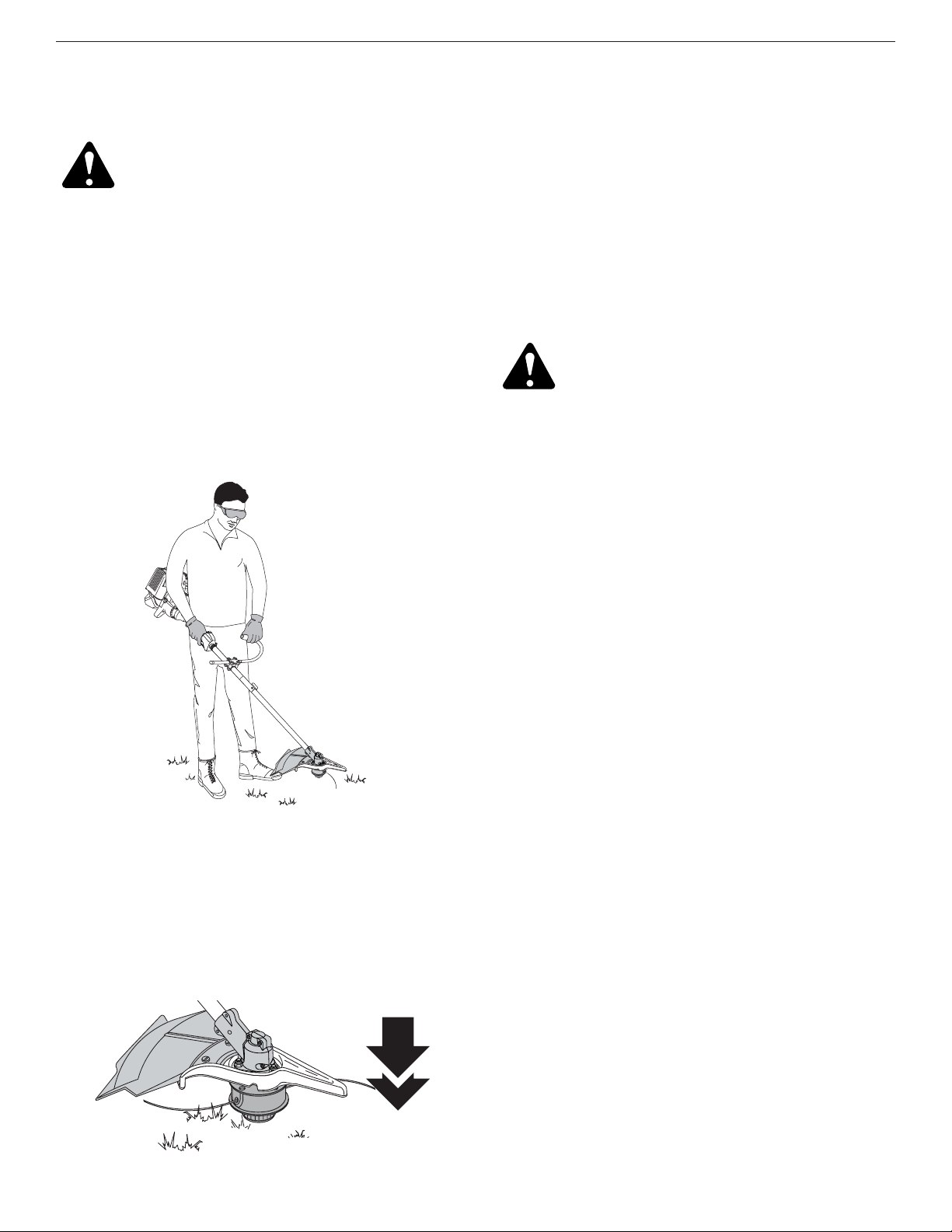
F15
SECTION 6: MODE D’EMPLO
TENUE DE LA DÉSHERBEUSE
AVERTISSEMENT :
portez toujours des
protections (yeux, oreilles, pieds et corps)
pour diminuer les risques de blessures
durant l'utilisation de l'appareil.
Avant de faire marcher l'appareil, tenez-vous en position
de fonctionnement (Fig. 26). Vérifiez les points suivants :
• L'opérateur porte une visière et des vêtements
appropriés
• Le bras droit est légèrement plié et la main tient l'arbre
par sa prise
• Le bras gauche est droit et la main tient la poignée en J
• L'appareil est au niveau de la ceinture
• L'accessoire de coupe est parallèle au sol et touche
facilement la végétation sans que l'opérateur ne doive
se pencher
Une fois que vous êtes en position de fonctionnement,
accrochez la bandouliére à l'unité.
RÉGLAGE DE LA LONGUEUR DU FIL
L'accessoire de coupe Bump HeadMCvous permet de
donner du fil sans arrêter le moteur. Pour avoir plus de fil,
tapez doucement l'accessoire de coupe sur le sol (Fig. 27)
tout en faisant marcher la désherbeuse à haut régime.
REMARQUE : gardez toujours le fil bien déroulé. Il
devient plus difficile de donner du fil à mesure
que le fil de coupe se raccourci.
Chaque fois que vous donnez un coup sur la tête, vous
déroulez environ 25,4 mm (1 po) de fil. La lame du
protecteur d'accessoire de coupe est conçue pour couper
le fil à la bonne longueur si vous déroulez trop de fil.
Pour de meilleurs résultats, tapez la tête Bump Head
MC
sur
un sol dégagé ou dur. Si vous donnez du fil dans un lieu
d'herbe haute, vous risquez de caler le moteur. Gardez
toujours le fil bien déroulé. Il devient plus difficile de donner
du fil à mesure que le fil de coupe se raccourci.
REMARQUE : ne posez pas la tête Bump HeadMCsur le
sol lorsque l’appareil est en marche.
MISE EN GARDE : n'enlevez et n'altérez
pas l'ensemble de la lame coupante. Un
excès de fil surchauffera l'appareil. Ceci
pourrait causer des blessures graves ou
endommager l'appareil.
Le fil peut se briser dans les cas suivants :
•Happement de corps étrangers
• Usure normale du fil
• Coupe de mauvaises herbes épaisses à longues tiges
• Forcer le fil dans des objets comme des murs ou des
poteaux de clôture
CONSEILS POUR BIEN DÉSHERBER
• Pour bien désherber, faites fonctionner l’appareil à
plein gaz.
• Le bon angle pour l'accessoire de coupe est parallèle
au sol.
• Ne forcez pas l'accessoire. Coupez avec la pointe du
fil (surtout le long des murs). Utiliser plus que la pointe
diminue l'efficacité de la coupe et peut surcharger le
moteur.
•Coupez de l'herbe mesurant plus de 20 cm (8 po) en
procédant de haut en bas par petits incréments pour
éviter d'user le fil prématurément ou de freiner le
moteur.
• Coupez de gauche à droite chaque fois que possible.
Cela améliore l'efficacité de coupe de l'appareil et les
résidus de coupe sont projetés loin de l'opérateur.
• Déplacez lentement la désherbeuse dans et hors de la
zone de coupe à la hauteur voulue. Procédez d'avant
en arrière ou d'un côté à l'autre. Les coupes de
longueur plus courte donnent les meilleurs résultats.
• Ne désherbez que lorsque l'herbe et les mauvaises
herbes sont sèches.
• La durée de vie de votre fil de coupe dépend
• de l’application des techniques de coupe précédentes
• du type de végétation à couper
• du lieu de coupe
Par exemple, le fil s'use plus vite si vous coupez le long d'un
mur de fondation que si vous coupez autour d'un arbre.
Figure 26
Figure 27
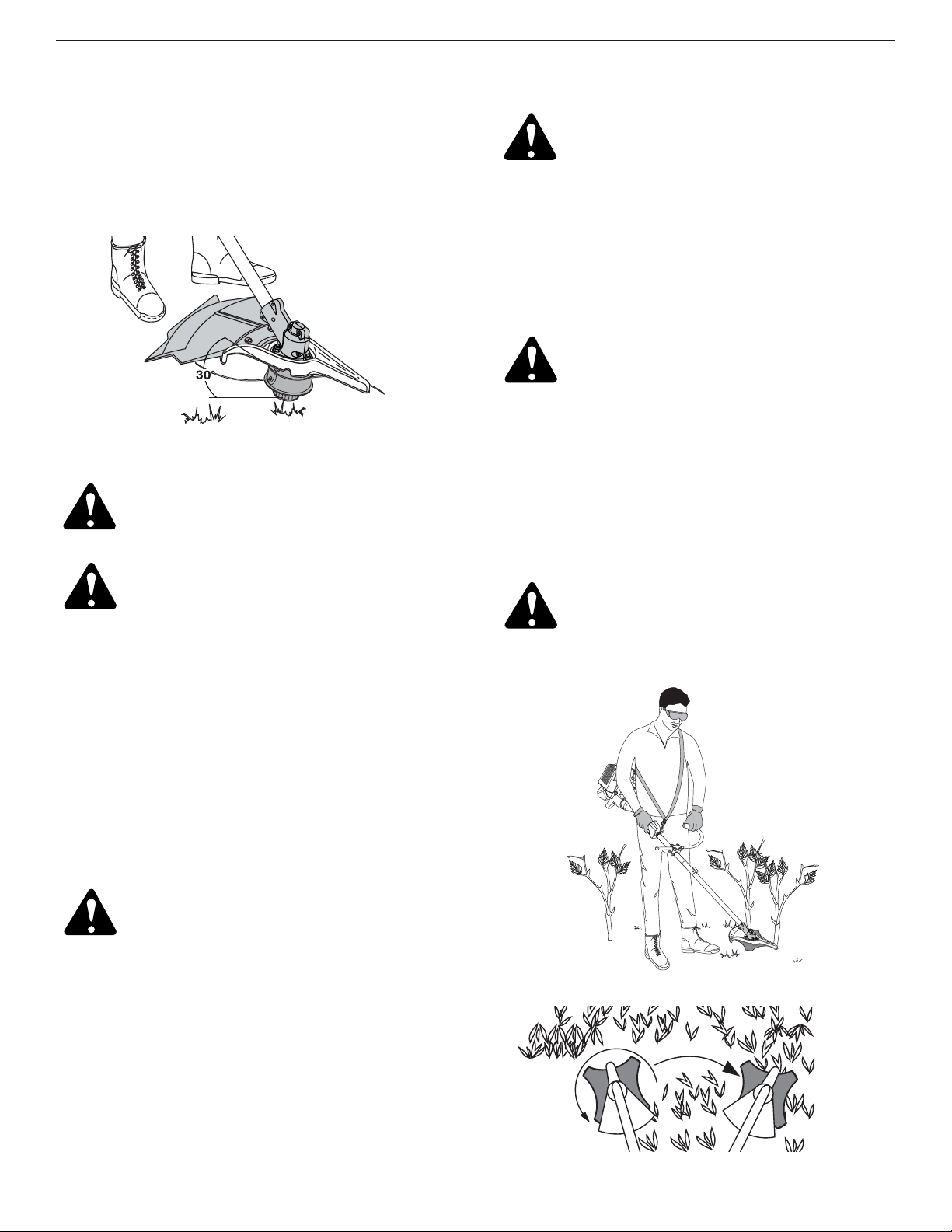
F16
COUPE DÉCORATIVE
La coupe décorative consiste à déblayer la végétation
autour des arbres, des bornes, des clôtures, etc.
Tournez entièrement l'appareil de manière à ce que
l'accessoire de coupe soit à un angle de 30° par rapport
au sol (Fig. 28).
UTILISATION DE LA LAME DE COUPE
Avant de faire marcher l'appareil, tenez-vous en position
de fonctionnement (Fig. 29). Voir Tenue de la
désherbeuse.
Conseils d'utilisation de la lame
Comment adopter un bon rythme de coupe :
• Plantez les pieds fermement en les écartant
confortablement.
• Lancez le moteur à pleine puissance avant de couper.
La lame a une puissance de coupe maximale quand le
moteur est à pleins gaz et est alors moins susceptible
de se coincer, caler ou donner des coups, ce qui
pourrait causer des blessures graves à l'opérateur et
aux autres personnes.
• Coupez tout en balançant le haut du corps de gauche
à droite.
• Lorsque vous ne coupez pas, relâchez toujours la
manette des gaz et laissez le moteur tourner au ralenti.
• Lorsque vous avez fini, dégagez toujours l’appareil du
harnais avant d’enlever celui-ci.
• Balancez l'appareil dans le opposé sens que celui de la
rotation de la lame, ce qui accroît la puissance de coupe.
• Avancez vers la zone à couper suivante, après avoir
ramené l'appareil, et plantez fermement les pieds de
nouveau.
• La lame de coupe comporte un second bord coupant
que vous pouvez utiliser. Pour cela, retirez la lame,
retournez-la et fixez-la de nouveau.
Pour diminuer les risques d'enroulement des matériaux
autour de la lame, suivez les points suivants :
• Coupez à pleins gaz.
• Balancez l'appareil de gauche à droite tout en
pénétrant dans la zone à couper (Fig. 30).
• Évitez, sur le mouvement de retour, les matières que
vous venez de couper.
Figure 28
AVERTISSEMENT :
ne déblayez pas les
matières coupées pendant que le moteur ou
la lame tournent. Pour éviter des blessures
graves, éteignez le moteur et laissez la lame
s'arrêter avant de dégager les matières
enroulées autour de l’axe de la lame
.
AVERTISSEMENT :
n'aiguisez pas la lame
de coupe car son extrémité risquerait de
casser à l'usage et causer des blessures
graves à vous-même ou à d'autres
personnes. Remplacez-la plutôt.
AVERTISSEMENT :
la lame continue de
tourner à vide une fois le moteur éteint et
peut vous blesser sérieusement si vous la
touchez accidentellement.
AVERTISSEMENT :
lorsque la lame
pivotante frappe un objet qu'elle ne peut
couper, elle donne un coup brusque qui
peut pousser violemment l'opérateur et
l'appareil vers n'importe quelle direction et
faire perdre le contrôle de l'appareil. Ceci
peut se produire brusquement si la lame
s'accroche, cale ou se coince, notamment
dans les endroits où il est difficile de voir ce
que l'on coupe.
AVERTISSEMENT :
n’utilisez pas la lame de
coupe comme coupe-bordure, cela peut
entraîner des blessures graves pour vous
ou d'autres personnes.
AVERTISSEMENT :
portez toujours des
protections (yeux, oreilles, pieds et corps) et
la bandoulière pour diminuer les risques de
blessures durant l'utilisation de l'appareil.
Figure 30
Figure 29
SECTION 6: MODE D’EMPLO

F17
SECTION 7: INSTRUCTIONS D’ENTRETIEN ET RÉPARATIONS
AVERTISSEMENT : pour éviter tout
accident, n’effectuez jamais l’entretien ou
des réparations quand l’appareil
fonctionne. Effectuez-les toujours lorsqu’il
est froid. Débranchez le câble de la bougie
pour prévenir la mise en route.
REMARQUE : certaines procédures d'entretien
nécessitent des compétences ou des outils
particuliers. Si vous n'êtes pas sûr de pouvoir les
entreprendre, emmenez votre appareil dans un
atelier, chez un technicien ou un concessionnaire
agréé spécialisé dans les réparations de moteurs
d’outils mécaniques de plein air.
PROGRAMME D'ENTRETIEN
L'entretien doit respecter la fréquence indiquée dans le
tableau ci-dessous. Il doit également faire partie de
toute mise au point saisonnière.
REMARQUE: l'entretien, le remplacement ou la
réparation des dispositifs et systèmes
antipollution peuvent être effectués par tout
atelier, technicien ou concessionnaire agréé
spécialisé dans les réparations de moteurs
d’outils mécaniques de plein air.
INSTALLATION DU FIL
Cette section couvre l’installation de fil SplitLineMCet
l’installation de fil simple standard.
Utilisez toujours un fil de remplacement Genuine Factory
PartsMCd'origine de 2,41 mm (0,095 po). Un autre fil
pourrait surchauffer ou endommager le moteur.
AVERTISSEMENT : n'utilisez jamais de fil,
de chaîne ou de cordon à renfort métallique
car ils peuvent se briser et se transformer
en projectiles dangereux.
Vous pouvez remplacer le fil de deux façons :
• Rembobinez du fil neuf dans le moulinet intérieur
• Installez un moulinet intérieur prérembobiné
Rembobiner le moulinet intérieur existant
1. Tenez la bobine extérieure d'une main et dévissez le
bouton de butée vers la gauche (Fig. 31). Inspectez
le boulon à l'intérieur du bouton de butée pour vous
assurer qu'il se déplace librement. Remplacez le
bouton de butée s'il est endommagé.
FRÉQUENCE ENTRETIEN REQUIS
REFER TO
Avant le démarrage du moteu
Remplissez le réservoir de carburant frais
Vérifiez l'huile
Page 12
Page 19
Toutes les 10 heures Nettoyez le filtre à air et lubrifiez-le de nouveau Page 21
Premier changement après 10 heures
Toutes les 25 heures après
Toutes les 25 heures
Changez l'huile
Changez l'huile
Nettoyez le pare-étincelles
Page 20
Page 20
Page 24
10 heures pour un moteur neuf
Toutes les 25 heures
Toutes les 25 heures
Vérifiez et réglez le jeu entre soupape et culbuteur
Vérifiez et réglez le jeu entre soupape et culbuteur
Vérifiez l'état de la bougie et l'écartement des électrodes
Page 23
Page 23
Page 24
2. Retirez le moulinet intérieur de la bobine extérieure
(Fig. 31).
3. Retirez le ressort du moulinet (Fig. 31).
4. Nettoyez le moulinet intérieur, le ressort, et l'arbre et
la surface interne de la bobine extérieure à l'aide
d'un tissu propre (Fig. 32).
5. Vérifiez l'état d'usure des dents de positionnement
sur le moulinet intérieur et la bobine extérieure
(Fig. 33). Enlevez les ébarbures ou remplacez le
moulinet et la bobine au besoin.
Dents de
positionnement
Moulinet intérieur
Bobine extérieure
Ressort du
moulinet intérieur
Bouton de butée
Boulon
Figure 31 Figure 33
Figure 32

F18
SECTION 7: INSTRUCTIONS D’ENTRETIEN ET RÉPARATIONS
Installation du fil simple
Pour l’installation du SplitLineMC, passez à l’étape 8.
6. Découpez environ 12,2 m (40 pi) de fil neuf et faitesen deux boucles de longueurs égales. Insérez
chaque extrémité de fil dans l'un des deux trous du
moulinet (Fig. 35). Tirez le fil à travers le moulinet
pour que la boucle soit le plus petit possible.
7. Enroulez les fils en couches uniformes serrées sur le
moulinet (Fig. 36). Enroulez le fil dans le sens indiqué sur
le moulinet intérieur. Placez votre index entre les deux fils
pour les empêcher de se superposer. Ne superposez
pas les extrémités du fil. Passez à l’étape 11.
REMARQUE : le SplitLine
MC
peut être utilisé seulement
avec le moulinet intérieur à trous allongés. Le fil
simple peut être utilisé avec les deux sortes de
moulinet intérieur. Identifiez votre type de
moulinet en vous référant à la Figure 34.
REMARQUE : utilisez toujours la bonne longueur de fil
lorsque vous posez le fil sur l'appareil. Le fil
risque de ne pas se dérouler correctement s'il est
trop long.
Installation du SplitLine
MC
8. Découpez environ 6,1 m (20 pi) de fil neuf. Insérez
une extrémité de fil dans l'un des deux trous du
moulinet intérieur (Fig. 37). Tirez le fil jusqu’à ne
laisser que 10 cm (4 po) environ.
9. Insérez l’extrémité du fil dans le trou ouvert du
moulinet et tirez sur le fil pour que la boucle soit le
plus petit possible (Fig. 37).
10. Avant de rembobiner le fil, séparez-le en deux sur
une longueur d’environ 15 cm (6 po).
11. Enroulez le fil en couches uniformes serrées dans le
sens indiqué sur le moulinet intérieur.
REMARQUE : ne pas enrouler le fil dans le sens indiqué
entraînera un mauvais fonctionnement de
l'accessoire de coupe.
12. Insérez les extrémités du fil dans les deux fentes de
retenue (Fig. 38).
13. Insérez les extrémités du fil dans les œillets de la
bobine extérieure et placez le moulinet et le ressort
dans la bobine (Fig. 39). Enfoncez le moulinet et la
bobine ensemble. Tout en tenant le moulinet et la
bobine, saisissez les extrémités et tirez fermement
pour dégager le fil des fentes de retenue de la bobine.
REMARQUE : le ressort doit être installé dans le
moulinet intérieur avant de remonter l'accessoire
de coupe.
14. Maintenez le moulinet intérieur en place et installez le
bouton de butée en le tournant à gauche. Vissez bien.
Trous allongés
Utiliser avec le SplitLine
MC
ou le fil simple
Utiliser avec le fil simple
UNIQUEMENT
Boucle
Ressort
Fentes de retenue
Boucle
Figure 39
Figure 38
Figure 37
Figure 36
Figure 35
Figure 34

F19
SECTION 7: INSTRUCTIONS D’ENTRETIEN ET RÉPARATIONS
VÉRIFICATION DU NIVEAU D'HUILE
Nous ne saurions trop insister sur l'importance de la
vérification du niveau d'huile du carter moteur et de son
maintien. Vérifiez l'huile avant chaque utilisation :
1. Arrêtez le moteur et laissez l’huile s’écouler dans le
carter moteur.
2. Placez l'appareil sur une surface horizontale plane
avant de relever correctement le niveau d'huile.
3. Empêchez l'accumulation de saleté, de résidus de
coupe, etc. dans le moteur. Nettoyez la zone autour
du bouchon / jauge d'huile avant de le retirer.
4. Retirez le bouchon / jauge d'huile et essuyez toute
trace d'huile. Replacez-le en l'enfonçant bien.
5. Retirez le bouchon de remplissage / jauge d'huile et
vérifiez le niveau d'huile. L’huile devrait atteindre le
haut de la jauge (Fig. 40).
6. Si le niveau est trop bas, ajoutez un peu d'huile par
l’orifice et revérifiez. Continuez jusqu'à ce que le
niveau d'huile atteigne le haut de la jauge.
REMARQUE : Ne remplissez pas trop l’appareil.
Haut de la jauge
Joint torique
Bouchon de remplissage /
jauge d'huile
REMARQUE : Assurez-vous que le joint torique est mis
sur le bouchon de remplissage / jauge d'huile au
moment de la vérification et du changement
d'huile (Fig. 41).
Bouchon de
remplissage /
jauge d'huile
Orifice de remplissage
d’huile
Joint torique
Plein
Ajoutez 41-44 ml
(1,4-1,5 oz)
MISE EN GARDE
: Pour éviter de trop user
le moteur ou endommager l'appareil,
maintenez toujours l'huile du carter à un
bon niveau. N’utilisez jamais l'appareil si le
niveau est en dessous du bas de la jauge.
Figure 41
Figure 40
INSTALLATION D’UN MOULINET PRÉREMBOBINÉ
1. Tenez la bobine extérieure d'une main et dévissez le
bouton de butée vers à droite (Fig. 31). Inspectez le
boulon à l'intérieur du bouton de butée pour vous
assurer qu'il se déplace librement. Remplacez le
bouton de butée s'il est endommagé.
2. Retirez l'ancien moulinet intérieur de la bobine
extérieure (Fig. 31).
3. Retirez le ressort de l'ancien moulinet intérieur
(Fig. 31).
4. Placez le ressort dans le moulinet intérieur neuf.
REMARQUE : le ressort doit être installé dans le moulinet
intérieur avant de remonter l'accessoire de coupe.
5. Insérez les extrémités du fil dans les œillets de la
bobine extérieure (Fig. 39).
6. Placez le moulinet intérieur neuf dans la bobine.
Poussez le moulinet et la bobine ensemble. Tout en
tenant le moulinet et la bobine, saisissez les
extrémités et tirez fermement pour dégager le fil des
fentes de retenue de la bobine.
7. Maintenez le moulinet intérieur en place et installez le
bouton de butée en le tournant à gauche. Vissez bien.
Pièces de rechange
Voir Accessoires et pièces de rechange.

F20
SECTION 7: INSTRUCTIONS D’ENTRETIEN ET RÉPARATIONS
CHANGEMENT D'HUILE
Si le moteur est neuf, changez l'huile après les 10
premières heures d’utilisation. Mieux vaut changer l'huile
lorsque le moteur est encore chaud. Cela lui permet de
s'écouler librement et d'emporter les impuretés.
1. Débranchez le couvre-borne de bougie pour
empêcher le démarrage.
2. Retirez le bouchon de remplissage / jauge d'huile.
3. Versez l'huile de l’orifice de remplissage dans un
récipient en inclinant l'appareil à la verticale (Fig. 42).
Allouez assez de temps pour une vidange complète.
6. Replacez le bouchon de remplissage / jauge d'huile.
7. Rebranchez le couvre-borne de bougie.
4. Essuyez les résidus d'huile et nettoyez toute trace
d'huile déversée. Éliminez l'huile selon les
règlements fédéral, provincial et municipal en
vigueur.
5. Remplissez de nouveau le carter moteur de 100 ml
(3,4 oz) d'huile SAE 30 SF, SG, SH.
REMARQUE : Mesurez la quantité nécessaire à l’aide de
la bouteille et de la buse utilisées lors de la mise
en service. 100 ml (3,4 oz) correspond environ au
haut de l’étiquette de la bouteille. Vérifiez le
niveau d'huile avec la jauge. S’il est trop bas,
ajoutez un peu d'huile par l’orifice et revérifiez
Ne remplissez pas trop (Fig. 43).
Niveau de
remplissage
Figure 42
MISE EN GARDE Portez toujours des
gants pour éviter tout risque de blessures
lorsque vous manipulez l'appareil.
Figure 43

F21
SECTION 7: INSTRUCTIONS D’ENTRETIEN ET RÉPARATIONS
ENTRETIEN DU FILTRE À AIR
Nettoyage du filtre à air
Nettoyez et relubrifiez le filtre à air à toutes les 10 heures
de fonctionnement. Son entretien est très important. Si
vous ne le faites pas, cela ANNULERA la garantie.
1. Ouvrez le couvercle du filtre à air Enfoncez la
languette à droite du couvercle, tirez celui-ci vers
vous puis vers la gauche (Fig. 44).
REMARQUE : Il peut s'avérer nécessaire de retirer le
bouchon du réservoir pour enlever le couvercle
du filtre.
2. Retirez le filtre à air (Fig. 44).
3. Lavez le filtre dans un mélange d'eau et de détergent
(Fig. 45). Rincez le filtre abondamment et laissez-le
sécher.
4. Appliquez une quantité suffisante d'huile moteur propre
SAE 30 pour enduire légèrement le filtre (Fig. 46).
Filtre à air
Couvercle du
filtre à air
Languette
5. Pressez le filtre pour répartir et drainer l'excédent
d'huile (Fig. 47).
Fente de la
plaque arrière
Fentes
6. Replacez le filtre (Fig. 48).
REMARQUE : Si vous faites fonctionner l'appareil sans
filtre à air, vous ANNULEREZ la garantie.
7. Réinstallez le couvercle du filtre à air Placez les
crochets à gauche du filtre à air dans les fentes à
gauche de la plaque arrière (Fig. 48).
REMARQUE : Il peut s'avérer nécessaire de retirer le
bouchon du réservoir pour réinstaller le
couvercle du filtre.
8. Pivotez le couvercle vers la droite jusqu’à ce que la
languette du couvercle du filtre s’enfonce d’un déclic
dans la plaque arrière (Fig. 44 & 48).
9. Replacez le bouchon du réservoir si vous l’aviez retiré.
Plaque arrière
RÉGLAGE DU CARBURATEUR
Le régime ralenti du moteur est réglable par le couvercle
du filtre à air/silencieux (Fig. 49).
REMARQUE : des réglages non soigneux peuvent
endommager sérieusement l'appareil. Les
réglages de carburateur doivent être faits par un
concessionnaire agréé.
Vérification du carburant
En général, si l'appareil ne fonctionne pas correctement,
c'est que le carburant est vieux. Videz puis remplissez le
réservoir de carburant sans plomb frais et propre avant
d'effectuer des réglages. Voir Informations sur l'huile et
le carburant.
AVERTISSEMENT:
pour éviter des blessures
graves, éteignez toujours l'appareil et
laissez-le refroidir avant tout nettoyage ou
entretien.
Figure 45
Figure 48
Figure 44
Figure 47
Figure 46

F22
SECTION 7: INSTRUCTIONS D’ENTRETIEN ET RÉPARATIONS
Nettoyage du filtre à air
L'état du filtre à air est très important pour le
fonctionnement de l'appareil. Un filtre à air sale restreint
le débit d'air et affecte le mélange de carburant/air. On
confond cela souvent avec un mauvais réglage du
carburateur. Vérifiez l'état du filtre à air avant de régler la
vis de réglage de ralenti. Voir Entretien du filtre à air.
Réglage du ralenti
AVERTISSEMENT:
il se peut que l'accessoire
de coupe tourne pendant un réglage du
ralenti. Portez des vêtements protecteurs et
respectez toutes les consignes de sécurité
pour éviter des blessures graves.
Si le moteur ne se met toujours pas au ralenti après
vérification du mélange et nettoyage du filtre à air, réglez
la vis de ralenti comme suit:
1. Démarrez le moteur et laissez-le tourner à haut régime
pendant une minute pour se réchauffer. Voir les
Instructions de démarrage et d'arrêt.
2. Relâchez le levier d'accélérateur et laissez le moteur au
ralenti. Si le moteur s'arrête, insérez un petit tournevis à
embout cruciforme ou à tête plate dans le trou du
couvercle du filtre à air/silencieux (Fig. 49). Vissez la vis
de ralenti de 1/8 de tour à la fois (selon le besoin)
jusqu'à ce que le moteur se mette bien au ralenti.
3. Si le ralenti semble trop rapide, dévissez la vis de
réglage du ralenti de 1/8 de tour à la fois (selon le
besoin) pour réduire la vitesse de ralenti.
La vérification de carburant, le nettoyage du filtre à air et
le réglage de la vis de ralenti devraient résoudre la
plupart des problèmes de moteur.
Dans le cas contraire et si :
• le moteur ne se met pas au ralenti
• le moteur hésite ou se cale lors d'une accélération
• le moteur perd de la puissance
faites régler le carburateur par un concessionnaire agréé.
AVERTISSEMENT: une fois l'appareil éteint,
assurez-vous que l'accessoire de coupe est
arrêté avant de poser l'appareil pour éviter
des blessures graves.
Vis de réglage du ralenti
Retirez les vis
Couvercle du
moteur
2. Enlevez les deux vis (2) du haut du couvercle du
moteur à l’aide d’un tournevis à lame plate ou T-25
Torx (Fig. 51).
Couvercle du
moteur
Silencieux
JEU ENTRE SOUPAPE ET CULBUTEUR
Ceci nécessite de démonter le moteur. Si vous ne vous
sentez pas à l'aise de le faire, confiez l'appareil à un
centre de service agréé.
REMARQUE : Inspectez le jeu entre soupape et
culbuteur à l’aide d’une jauge d'épaisseur après
les 10 premières heures de fonctionnement, puis
par intervalle de 25 heures par la suite.
• Attendez que le moteur soit froid avant de vérifier ou
de régler le jeu de la soupape.
• Faites-le à l'intérieur, dans un endroit propre et sans
poussière.
1. Retirez le couvercle du silencieux en appuyant sur le
coin à l’aide d’un tournevis à lame plate (Fig. 50).
Glissez les encoches sur les côtés du couvercle pardessus les languettes du couvercle du moteur et
retirez le couvercle.
Moteur vu de haut
Languette
Encoches
Encoche et
Languette
Languette
Figure 51
Figure 50
Figure 49

F23
SECTION 7: INSTRUCTIONS D’ENTRETIEN ET RÉPARATIONS
Cache-culbuteur
Vis
Trou de bougie
4. Déconnectez le câble de la bougie.
5. Nettoyez toute saleté de la bougie. Retirez la bougie
de la culasse en tournant la douille de 5/8 po à
gauche.
6. Déposez le couvercle du moteur (Fig. 51).
7. Nettoyez toute saleté autour du cache-culbuteur.
Retirez la vis retenant le cache-culbuteur à l’aide d’un
tournevis à lame plate large ou à mèche no. T-25
Torx (Fig. 53). Enlevez le cache-culbuteur et le joint.
3. Enlevez la vis derrière le couvercle du moteur (Fig. 52)
8. Tirez lentement sur la corde de démarrage pour
ramener le piston au sommet de sa course dit «
point mort haut ». Vérifiez que :
• Le piston est au sommet de sa course lorsqu’on
regarde par le trou de la bougie (Fig. 53)
• Les deux culbuteurs se déplacent librement et les
deux soupapes sont fermées
Si ce n'est pas le cas, répétez la procédure.
9. Glissez la jauge d'épaisseur entre le culbuteur et le
ressort de rappel de la soupape. Mesurez le jeu
entre la tige de soupape et le culbuteur (Fig. 54).
Faites-le pour les soupapes d’admission et
d'échappement.
LL'écart de jeu recommandé pour l'admission et
l'échappement est de 0,076 – 0,152 mm (0,003 – 0,006
po). Servez-vous d’une jauge d'épaisseur d’automobile
standard de 0,127 mm (0,005 po). La jauge d'épaisseur
devrait pouvoir glisser entre le culbuteur et la tige de
soupape en rencontrant une faible résistance mais sans
coller (Fig. 54).
10. Si le jeu n'est pas conforme:
a. Tournez l'écrou de réglage à l'aide d'une clé de 8
mm (5/16 po) ou d'un tournevis à embout hexagonal
(Fig. 55).
• Pour augmenter le jeu, tournez l'écrou de réglage
vers la gauche.
• Pour réduire le jeu, tournez l'écrou de réglage vers
la droite.
b.Revérifiez les deux jeux de soupape et réglez-les au
besoin.
11. Replacez le cache-culbuteur en mettant un joint
neuf. Serrez la vis avec un couple de serrage de
2,2–3,4 N•m (12 po•lb).
12. Replacez le couvercle du moteur. Vérifiez
l'alignement du couvercle avant de serrer les vis.
Vissez bien.
13. Replacez le couvercle du silencieux. Glissez avec un
déclic les encoches sur les côtés du couvercle pardessus les languettes du couvercle du moteur (Fig. 50).
14. Vérifiez l'état de la bougie et replacez-la. Voir
Remplacement de la bougie.
15. Replacez le câble de la bougie.
ADMISSION
ECHAPPEMENT
Culbuteurs
Écrous de
réglage
Jauge
d'épaisseur
Jauge
d'épaisseur
Écrou de réglage
Culbuteur
0,076-0,0152 mm
(0,003-0,006 po)
Tige de soupape
Figure 55
Figure 53
Figure 54
Figure 52

F24
SECTION 7: INSTRUCTIONS D’ENTRETIEN ET RÉPARATIONS
REMPLACEMENT DE LA BOUGIE
Utilisez une bougie 180852 (ou un modèle
équivalent). L'écartement correct est de 0,655 mm
(0,025 po). Retirez la bougie après 25 heures de
fonctionnement et vérifiez son état.
1. Arrêtez le moteur et laissez-le refroidir. Saisissez
fermement le capuchon de la bougie et retirez-le de
la bougie.
2. Nettoyez toute saleté de la bougie. Retirez la bougie
de la culasse en tournant la douille de 5/8 po à
gauche.
3. Si la bougie est fendillée, encrassée ou sale,
remplacez-la. Réglez l'écartement à 0,655 mm
(0,025 po) à l'aide d'une jauge d'épaisseur (Fig. 56).
MISE EN GARDE : évitez de sabler, gratter
ou nettoyer les électrodes car de la saleté
dans le moteur pourrait endommager le
cylindre.
4. Installez la bougie avec un écartement correct dans
la culasse en tournant la douille de 5/8 po à droite
jusqu'à la bien visser.
Si vous utilisez une clé dynamométrique, vissez avec les
valeurs de couple suivantes :
110-120 po•lb (12,3-13,5 N•m).
Évitez de trop serrer.
0,655 mm
(0,025 po)
Figure 56
Figure 57
Silencieux
Écran pare-étincelles
Couvercle du pare-étincelles
Vis
Languette
Fente
ENTRETIEN DU PARE-ÉTINCELLES
1. Retirez le couvercle du silencieux. Voir Jeu entre
soupape et culbuteur.
2. Retirez la vis retenant le couvercle du pare-étincelles
au silencieux à l'aide d'un tournevis à lame plate ou
à mèche no. T-20 Torx (Fig. 57).
3. Retirez la languette du couvercle du pare-étincelles
hors du silencieux. Retirez le couvercle du pareétincelles.
4. Retirez l’écran du pare-étincelles du couvercle de celui-ci.
5. Nettoyez l’écran du pare-étincelles avec une brosse
métallique ou remplacez-le.
6. Replacez l’écran, le couvercle et la vis du pare-étincelles.

F25
NETTOYAGE
AVERTISSEMENT : pour éviter des blessures
graves, éteignez toujours l'appareil et
laissez-le refroidir avant tout nettoyage ou
entretien.
Nettoyez l'extérieur de l'appareil à l'aide d'une petite
brosse. N'utilisez pas de détergents concentrés. Les
nettoyants ménagers contenant des huiles aromatiques tel
que le pin et le citron, et les solvants tel que le kérosène
peuvent endommager le boîtier ou la poignée en plastique.
Essuyez toute trace d'humidité à l'aide d'un tissu doux.
ENTREPOSAGE
•Ne rangez jamais l'appareil plein de carburant dans un
lieu où les vapeurs peuvent atteindre une flamme vive
ou des étincelles.
• Laissez le moteur se refroidir avant de l'entreposer.
• Rangez l'appareil dans un lieu verrouillé pour éviter
toute utilisation ou accident indésirable.
• Rangez l'appareil dans un lieu sec et bien aéré.
• Rangez l'appareil hors de la portée des enfants.
ENTREPOSAGE DE LONGUE DURÉE
Si vous comptez entreposer l'appareil pendant une
longue période, appliquez la procédure suivante :
1. Videz tout le carburant du réservoir dans un récipient.
N'utilisez pas de carburant stocké pendant plus de
60 jours. Éliminez le vieux mélange de carburant
conformément aux règlements fédéral, provincial et
municipal en vigueur.
2. Démarrez le moteur, puis laissez-le tourner jusqu'à
ce qu'il cale. Cela permet de s'assurer que le
carburateur s'est vidé de son carburant.
3. Laissez le moteur refroidir. Retirez la bougie et
versez environ 30 ml (1 oz) d'huile moteur dans le
cylindre. Tirez lentement sur la corde de démarrage
pour bien distribuer l'huile. Replacez la bougie.
REMARQUE : retirez la bougie et videz toute l'huile du
cylindre avant de mettre en marche la
désherbeuse après une période d'entreposage.
4. Nettoyez soigneusement l'appareil et vérifiez qu'il ne
comporte pas de pièces desserrées ou
endommagées. Réparez ou remplacez les pièces
endommagées, puis serrez les vis, écrous et boulons
desserrés. L'appareil est alors prêt pour
l'entreposage.
TRANSPORT
• Laissez le moteur refroidir avant le transport.
• Attachez bien l'appareil lors du transport.
•Videz tout le carburant de l’appareil.
• Serrez le bouchon du réservoir avant le transport.
ACCESSOIRES / PIÈCES DE RECHANGE
Huile 4-temps . . . . . . . . . . . . . . . . . . . . . . . . . . . . 181786
Bougie . . . . . . . . . . . . . . . . . . . . . . . . . . . . . . . . . .180852
Écran pare-étincelles . . . . . . . . . . . . . . . . . . . . . .180890
Fil de remplacement . . . . . . . . . . . . . . . . . . . . . . . 180120
Cartouche de fil de remplacement . . . . . . . . . . . . 147345
Ressort du moulinet intérieur . . . . . . . . . . . . . . . 610636
Bobine extérieure . . . . . . . . . . . . . . . . . . . . . . . . 683301
Moulinet intérieur . . . . . . . . . . . . . . . . . . . . . . . . 147495
Bouton de butée . . . . . . . . . . . . . . . . . . . . . . . . . 180814
Bouchon du carburant . . . . . . . . . . . . . . . . . . .753-1229
Harnais d'épaule . . . . . . . . . . . . . . . . . . . . . . . . . 682075
Vous pouvez vous procurer ces pièces de rechange
auprès de votre distributeur agréé.
SECTION 7: INSTRUCTIONS D’ENTRETIEN ET RÉPARATIONS

F26
SECTION 8 : GUIDE DE DÉPANNAGE
Si vous avez besoin d'aide, contactez votre concessionnaire agréé
Problème Causes possibles Solution
LE MOTEUR
REFUSE DE
DÉMARRER
• La commande Marche/Arrêt Stop est
en position STOP
• Réservoir de carburant vide
• La poire d'amorçage n'a pas été
pressée assez fort
• Moteur noyé
•Carburant vieux ou mal mélangé
• Bougie encrassée
• Pare-étincelles colmaté
• Mettez-la en position de DÉMARRAGE
• Remplissez le réservoir de carburant
• Pressez-la complètement et lentement de 10 fois
• Appliquez procéd. de démar. avec levier d'étrangleur en
position MARCHE
• Drainez le réservoir de carburant / Ajoutez un carburant frais
• Nettoyez-la ou remplacez-la
• Nettoyez ou remplacez le pare-étincelles
LE MOTEUR
REFUSE DE SE
METTRE AU
RALENTI
• Filtre à air bouché
• Carburant vieux ou mal mélangé
• Mauvais réglage du carburateur
• Nettoyez-le ou remplacez-le
• Drainez le réservoir de carburant / Ajoutez un carburant frais
• Voir Régales du Carburateur dans la Section 7
LE MOTEUR
REFUSE
D’ACCÉLÉRER
• Carburant vieux ou mal mélangé
• Mauvais réglage du carburateur
• Accessoire de coupe engorgé d'herbes
l'accessoire
• Filtre à air sale
• Pare-étincelles colmaté
• Drainez le réservoir de carburant / Ajoutez un carburant frais
• Voir Régales du Carburateur dans la Section 7
• Arrêtez le moteur et nettoyez l'accessoire
• Nettoyez-le ou remplacez-le
• Nettoyez ou remplacez le pare-étincelles
LE MOTEUR
MANQUE DE
PUISSANCE OU
SE CALE
DURANT LA
COUPE
• Carburant vieux ou mal mélangé
• Mauvais réglage du carburateur
• Bougie encrassée
• Pare-étincelles colmaté
• Drainez le réservoir de carburant / Ajoutez un carburant frais
• Voir Régales du Carburateur dans la Section 7
• Nettoyez-la ou remplacez-la
• Nettoyez ou remplacez le pare-étincelles
L’ACCESSOIRE
DE COUPE NE
FAIT PAS
AVANCER LE
FIL
• Accessoire de coupe engorgé d'herbes
l'accessoire
• Accessoire de coupe mal aligné
• Moulinet intérieur bloqué
• Tête de coupe sale
• Fil soudé
• Fil tordu durant la recharge
• Quantité insuffisante de fil exposée
• Arrêtez le moteur et nettoyez l'accessoire
• Chargez du fil neuf
• Remplacez le moulinet
• Nettoyez le moulinet intérieur et la bobine extérieure
• Démontez et déposez la partie soudée, et rembobinez le fil
• Démontez, puis rembobinez le fil
• Enfoncez le bouton de butée et tirez le fil jusqu’à en extraire
102 mm (4 po) à l’extérieur de l’accessoire de coupe
LE FIL DE
COUPE
AVANCE DE
MANIÈRE
INCONTRÔLÉE
• Le cliquet de l’accessoire de coupe est
usé ou cassé
• Démontez et vérifiez le cliquet, et remplacez-le au besoint

F27
SECTION 9: CARACTERISTIQUES
Moteur*
Arbre D'entrainement et Accessoire de Coupe*
*Toutes les spécifications contenues dans ce manuel tiennent compte des dernières informations techniques disponibles au
moment de mettre sous presse. Nous nous réservons le droit d'y apporter des modifications à tout moment, sans préavis.
Type de moteur............................................................................................................................. Refroidi par air, 4-temps
Cylindrée................................................................................................................................................... 26,2 cc (1,6 po3)
Type d'embrayage ............................................................................................................................................... Centrifuge
Régime de fonctionnement............................................................................................................................. 7,200+ tr/min
Régime ralenti ...................................................................................................................................... 2,800 - 4,000 tr/min
Type d'allumage................................................................................................................................................ Électronique
Contact d'allumage.............................................................................................................................. Interrupteur berceau
Jeu de soupape ............................................................................................................ 0,076-0,152 mm (0,003-0,006 po)
Écartement de la bougie..................................................................................................................... 0,655 mm (0,025 po)
Lubrification ..................................................................................................................................................... Huile SAE 30
Contenance en huile du carter moteur......................................................................................................... 100 ml (3,4 oz)
Carburant.......................................................................................................................................................... Sans plomb
Carburateur.............................................................................................................................. Membrane, toutes positions
Démarreur.................................................................................................................................. Rembobinage automatique
Silencieux....................................................................................................................................... Chicane avec protection
Accélérateur................................................................................................................................................ À rappel manuel
Capacité du réservoir de carburant............................................................................................................... 355 ml (12 oz)
Logement de l'arbre d'entraînement..................................................................................... Tube d'aluminium (EZ-Link™)
Manette des gaz.......................................................................................................................... Détente à portée du doigt
Poids de l'appareil (sans carburant, avec poignée en J, et accessoire de coupe)....................................... 6 kg (13,15 lb)
Mécanisme de coupe........................................................................ Lame de coupe à 4 dents, tête de coupe à fil double
Bobine de fil................................................................................................................................ Déclencheur de fil à butée
Diamètre de la bobine de fil....................................................................................................................... 101,6 mm (4 po)
Diamètre du fil....................................................................................................................................... 2,41 mm (0,095 po)
Diamètre du chemin de coupe, accessoire de coupe ............................................................................... 45,7 cm (18 po)
Diamètre du chemin de coupe, lame de coupe............................................................................................ 204 mm (8 po)
Harnais d'épaule................................................................................................................................ Fermoir rapide unique

F28
REMARQUES

F29
Garantie portant sur les normes antipollution de l'EPA
Vos droits et obligations en vertu de cette garantie
La Environmental Protection Agency et MTD LLC (MTD) ont le plaisir de présenter la garantie du dispositif antipollution
des petits moteurs à usage tout-terrain datant de 2002 et au-delà. Les nouveaux petits moteurs à usage tout-terrain
doivent être conçus, construits et équipés pour être conformes aux strictes normes anti-smog. Yard Man doit garantir
le système de contrôle des émissions de votre petit moteur à usage tout-terrain pendant les périodes de temps
indiquées ci-dessous à condition que le moteur n'ait pas souffert d'abus, de négligence ou fait l'objet d'un mauvais
entretien.
Votre dispositif antipollution peut inclure des pièces diverses tel que le carburateur ou un système d'injection, le
dispositif d'allumage et un convertisseur catalytique. Il pourrait aussi inclure des tuyaux, courroies, connecteurs et
autres ensembles de pièces relatives aux émissions.
Advenant une situation couverte par la garantie, Yard Man réparera votre petit moteur à usage tout-terrain sans frais
aucun y compris le diagnostic, les pièces et la main d'œuvre.
Les moteurs à usage tout-terrain datant de 2002 et plus sont garantis pendant deux ans. Si une pièce de votre moteur
relative aux émissions devenait défectueuse, Yard Man la réparera ou la remplacera.
Responsabilités du propriétaire en vertu de cette garantie
• En tant que propriétaire d'un petit moteur à usage tout-terrain, vous êtes responsable des entretiens requis indiqués
dans votre manuel de l'utilisateur. Yard Man recommande que vous conserviez tous les reçus d'entretien de votre petit
moteur à usage tout-terrain. Yard Man ne peut toutefois réfuter votre garantie juste parce que vous n'avez pas les reçus
ou si vous ne veillez pas à ce que les travaux d'entretien prévus soient effectués.
• En tant que propriétaire d'un petit moteur à usage tout-terrain, sachez que Yard Man peut refuser de vous couvrir
sous garantie si votre moteur ou si une pièce sont défaillants pour cause d'abus, de négligence, d'entretien incorrect ou
de modifications non autorisées.
• Il vous incombe de présenter votre petit moteur à usage tout-terrain à un centre de service agréé Yard Man dès que le
problème fait son apparition. Les réparations sous garantie doivent être achevées dans une durée de temps raisonnable
ne dépassant en aucun cas 30 jours.
Si vous avez des questions au sujet de vos droits et responsabilités en vertu de cette garantie, appelez le 1-800-345-8746.
Garantie du fabricant
• La période de garantie commence à la date où le moteur ou l'équipement est livré à l'acheteur au détail.
• Le fabricant garantit au propriétaire initial et à chaque acheteur subséquent que le moteur est libre de défauts de matériaux et
de vices de fabrication pouvant provoquer la défaillance d'une pièce garantie pendant une période de deux ans
.
• Toute réparation ou remplacement d'une pièce garantie devra être effectué sans aucun frais au compte du propriétaire par un
centre de service Yard Man agréé. Pour connaître le centre le plus proche de vous, veuillez contact Yard Man à : 1-800-345-
8746.
• Toute pièce garantie dont le remplacement n'est pas prévu dans le cadre des entretiens requis, ou dont uniquement
une inspection normale est prévue selon le principe de "réparation ou remplacement au besoin", est garantie pendant la
période de garantie. Toute pièce garantie dont le remplacement est prévu dans le cadre des entretiens requis sera
garantie pendant la période de temps allant jusqu'à la date du premier remplacement prévu pour cette pièce.
• Le propriétaire ne subira pas de frais relatifs à un travail de diagnostic qui conclut que la pièce garantie est
défectueuse si le travail de diagnostic a été effectué chez un centre de service Yard Man agréé.
• Le fabricant est responsable de tous les dommages occasionnés aux autres composants du moteur par la défaillance
d'une pièce encore sous garantie.
• Les défaillances causées par l'abus, la négligence ou un mauvais entretien ne sont pas couvertes par cette garantie.
• L'utilisation d'un ajout ou de pièces modifiées peut justifier le refus d'une réclamation au titre de la garantie. Le
fabricant n'est pas responsable des défaillances des pièces garanties découlant de l'utilisation d'ajouts ou de pièces
modifiées.
• Pour déposer une réclamation, adressez-vous au centre de service Yard Man agréé le plus proche. Les services ou
réparations sous garantie sont offerts par tous les centres de service Yard Man agréés.
• Toutes les pièces de rechange approuvées par le fabricant peuvent être utilisées dans le cadre d'un entretien ou d'une
réparation sous garantie de pièces relatives au dispositif antipollution et sont fournies sans frais. Toute pièce de
rechange équivalente en termes de performances ou de durabilité peut être utilisée lors d'un entretien ou d'une
réparation hors garantie et ne diminue pas les obligations qui incombent au fabricant en vertu de la garantie.
• Les composants suivants sont inclus dans la garantie relative au système antipollution du moteur : filtre à air,
carburateur, poire d'amorçage, conduites de carburant, alimentation d'arrivée, filtre à carburant, module d'allumage,
bougie et silencieux.

GARANTIE LIMITÉE DU FABRICANT POUR:
Aucune garantie implicite, y compris toute garantie de
valeur marchande ou d’adaptation à une fin particulière, ne
s’applique après la période applicable de garantie
expresse écrite ci-dessus concernant les pièces qui sont
identifiées. Aucune autre garantie ou caution expresse,
écrite ou orale, à l’exception de celle mentionnée cidessus, accordée par toute personne ou entité, y compris
tout distributeur ou détaillant, concernant tout produit
n’engagera la responsabilité de MTD. Pendant la période
destates garantie, le remède exclusif est la réparation ou le
remplacement du produit dans les conditions énoncées cidessus. (Certains états ne permettent pas la limitation de la
garantie implicite, il est donc possible que la limitation cidessus ne s’applique pas à vous.)
Les clauses énoncées dans la présente Garantie
constituent le recours unique et exclusif inhérent aux
ventes. MTD ne sera en aucun cas tenue pour
responsable de tout dommage indirect ou consécutif ou
de dommages comprenant, entre autres mais pas
seulement, les dépenses encourues du fait du recours à
des services de remplacement ou de substitution pour
l’entretien des pelouses, le transport ou des frais
connexes, ou les frais entraînés par une location
destinée à remplacer provisoirement un produit sous
garantie. (Certains états ne permettent pas la limitation de la
garantie implicite, il est donc possible que la limitation cidessus ne s’applique pas à vous.)
Aucun recouvrement, quel qu’il soit, ne sera d’un montant
supérieur au prix du produit vendu. Toute modification des
dispositifs de sécurité du produit annulera la présente
Garantie. Vous assumez tout risque et toute responsabilité
résultant de la perte, de l’endommagement ou du préjudice
que vous et votre propriété et/ou d’autres et leur
propriété pourront encourir du fait de l’utilisation normale, de
la mauvaise utilisation ou de l’empêchement d’utiliser le
produit.
La présente garantie limitée n’est accordée qu’à l’acheteur
initial, au preneur initial ou à la personne à laquelle le produit
a été offert.
Le Droit des États vis à vis de la présente garantie : la
présente garantie vous confère certains droits juridiques, et
vous pouvez bénéficier d’autres droits, lesquels varient
d’une juridiction à l’autre.
Pour obtenir l’adresse du distributeur agréé le plus proche,
composer le : 1-800-345-8746 aux États-Unis ou le
1-800-668-1238 au Canada.
MTD LLC
P.O. Box 361131
Cleveland, OH 44136-0019
La garantie limitée énoncée ci-après est accordée par MTD
LLC (« MTD ») et concerne les marchandises neuves achetées
et utilisées aux États-Unis, ainsi que dans leurs possessions et
territoires.
MTD garantit ce produit contre tout vice de matière ou de façon
pendant une période de deux (2) ans à compter de la date
d’achat initiale et elle se réserve le choix de réparer ou de
remplacer, à titre gratuit, toute pièce présentant un vice de
matière ou de façon. Cette garantie limitée nes’ appliquera que
dans la mesure où le produit aura été utilisé et entretenu
conformément au Guide de l’utilisateur fourni avec le produit et
n’aura pas fait l’objet d’un usage inadéquat, abusif, commercial
ou négligent, d’un accident, d’un entretien inadéquat, d’une
modification, de vandalisme, d’un vol, d’un incendie, de dégâts
d’eau ou d’un endommagement résultant d’un autre péril ou
d’un désastre naturel. Les dommages résultats de l’installation
ou de l’utilisation de tout accessoire ou équipement non
approuvé par MTD pour une utilisation avec le(s) produit(s)
couvert(s) par le présent guide annuleront la garantie et ce qui
concerne les dommages qui en résulteraient éventuellement.La
présente garantie est limitée à quatre-vingt-dix (90) jours à
compter de la date d’achat au détail initiale pour tout produit
MTD utilisé à des fins locatives ou commerciales, ou toute
utilisation produisant des revenus.
POUR L’ENTRETIEN-DÉPANNAGE : l’Entretien-dépannage
au titre de la garantie est disponible, SUR PRÉSENTATION
DE PREUVE D’ACHAT, AUPRÈS DU DISTRIBUTEUR AGRÉÉ
LOCAL. Pour obtenir le nom du distributeur agréé local,
consulter les Pages Jaunes ou se mettre en rapport avec le
Service après-vente de MTD LLC. en appelant le 1-800-3458746 ou en écrivant au P.O. Box 361131, Cleveland OH
44136-0019 ou en appelant le 1-800-668-1238 au Canada.
Aucun produit retourné à l’usine sans permission écrite
préalable du service après-vente de MTD LLC ne sera
accepté.
La garantie limitée n’offre aucune couverture dans les
cas suivants :
A. Mises au point – Bougies, réglages de carburateur,
filtres.
B. Articles d’usure – Bouton de butée, bobines extérieures, fil
de coupe, bobines intérieures, poulie de démarrage,
cordes de démarrage, courroies d’entraînement.
C. MTD n’accorde aucune garantie pour les produits
vendus ou exportés des États-Unis, de leurs
possessions et territoires, exception faite en ce qui
concerne les produits vendus par l’intermédiaire de ses
canaux agréés de distribution à l’exportation.
MTD se réserve la droit de modifier ou d’améliorer la
conception de tout produit MTD sans assumer l’obligation
de modifier tout produit d’une fabrication plus ancienne.

Manuel del Dueño/Operador
IMPORTANTE: Lea las instrucciones y normas de seguridad detenidamente antes de usar el equipo.
Español
Recortador /
Cortamalezas de
4-Tiempos a Gasolina
Modelo
YM26BC
IMPRESO EN LOS EE.UU
No. de catálogo
769-00576 (12/02)

E2
ÍNDICE
Contenido . . . . . . . . . . . . . . . . . . . . . . . . . . . . . . . . . . . . . . . . . . . . . . . . . . . . . .Página
Normas para una operacion segura . . . . . . . . . . . . . . . . . . . . . . . . . . . . . . . . . . . . . . .E3
Conozca su recortador . . . . . . . . . . . . . . . . . . . . . . . . . . . . . . . . . . . . . . . . . . . . . . . .E7
Instrucciones de ensamble . . . . . . . . . . . . . . . . . . . . . . . . . . . . . . . . . . . . . . . . . . . . .E8
Información del aceite y del combustible . . . . . . . . . . . . . . . . . . . . . . . . . . . . . . . . . E12
Instrucciones de arranque y apagado . . . . . . . . . . . . . . . . . . . . . . . . . . . . . . . . . . . . E14
Instrucciones de operación . . . . . . . . . . . . . . . . . . . . . . . . . . . . . . . . . . . . . . . . . . . . E15
Instrucciones de mantenimiento y reparación . . . . . . . . . . . . . . . . . . . . . . . . . . . . . E18
Limpieza y almacenamiento . . . . . . . . . . . . . . . . . . . . . . . . . . . . . . . . . . . . . . . . . . . E26
Solucion de problemas . . . . . . . . . . . . . . . . . . . . . . . . . . . . . . . . . . . . . . . . . . . . . . . .E27
Especificaciones . . . . . . . . . . . . . . . . . . . . . . . . . . . . . . . . . . . . . . . . . . . . . . . . . . . . .E28
Garantía . . . . . . . . . . . . . . . . . . . . . . . . . . . . . . . . . . . . . . . . . . . . . . . . . . . . . . . . . . . E36
Lista de Piezas . . . . . . . . . . . . . . . . . . . . . . . . . . . . . . . . . . . . . . . . . . . . .Contraportada
P
ARA ENCONTRAR EL NÚMERO DEL MODELO
Este Manual del operador es una parte importante de su nuevo recortador. Le ayudará a ensamblar, preparar y a
mantener la unidad para que produzca el mejor rendimiento. Por favor lea y entienda el contenido.
Antes de que empiece a ensamblar su nuevo equipo, por favor ubique la placa que contiene
el modelo en la unidad y escriba esa información en el espacio en blanco aquí debajo. La
información de la placa del modelo es muy importante en caso de que necesite la ayuda de
nuestro Departamento de Apoyo al Cliente o de un distribuidor autorizado.
• Puede encontrar el número del modelo en la cara inferior del motor. Aquí debajo se explica la muestra de
una placa del modelo. Para referencia futura, por favor escriba el número del modelo y el número de la
serie del equipo en el espacio abajo.
LLAMADAS P
ARA
APOY
O AL CLIENTE
Si tiene dificultad con el ensamblaje de este producto o tiene alguna pregunta relacionada con los controles, el
funcionamiento o el mantenimiento de esta unidad, por favor llame al Departamento de Apoyo al Cliente.
Llame al 1-(800)-345-8746, o en Canadá al 1-(800)-668-1238, para comunicarse con un
representante de Apoyo al Cliente. Por favor tenga listo el número del modelo y de serie de su
unidad cuando llame. Vea la sección anterior para ubicar esa información. Se le pedirá que
ingrese el número de serie para poder procesar su llamada.
VISITE NUESTRA SIT
O EN EL INTERNET
Visite nuestro sitio en el Internet en www.yardman.com para que obtenga mayor información sobre nuestros
productos Yard Man de calidad, servicio al consumidor, piezas, consejos útiles, documentación y más.
Número de la pieza del fabricante
Número del modelo
Número de serie
Copie el número del modelo/
pieza del fabricante aquí:
Copie el número
de serie aquí:
S/N :
MODEL :
ITEM :
E3
PARACHISPAS
NOTA: Para los usuarios en tierras forestales de los EE.UU. y en los estados de California, Maine, Oregon y
Washington. Todos los terrenos forestales de los EE.UU. y en el estado de California (Códigos de Recursos Públicos
4442 y 4443), Oregon y Washington requieren, por ley, que ciertos motores de combustión interna operadas en zonas
boscosas y /o zonas cubiertas por pastizales, estén equipados con un parachispas, que sean mantenidos en buen
estado de funcionamiento o que el motor sea construido, equipado y mantenido para evitar incendios. Consulte los
reglamentos pertinentes a esos requisitos con las autoridades estatales o locales. La omisión del cumplimiento de
esos requisitos puede responsabilizarle o imponerle una multa. Esta unidad fue equipada en la fábrica con un
parachispas. Si requiere reemplazo, pídale al distribuidor de SERVICIO LOCAL que le instale la Pieza Accesoria,
Parachispas # 180890.
¡ADVERTENCIA!
Lea el manual o manuales del operador y siga todas las advertencias e instrucciones de seguridad. El
no hacerlo puede ocasionarle lesiones serias al operador y/o a los espectadores.
SI TIENE PREGUNTAS, LLAME AL 1-800-345-8746 EN LOS EE.UU. Ó 1-800-668-1238 en CANADÁ
El propósito de los símbolos de seguridad es para destacar los posibles peligros. Los símbolos de
seguridad y sus explicaciones merecen toda su atención y entendimiento cuidadoso. Las advertencias
de seguridad no eliminan ningún peligro por sí solos. Las instrucciones o advertencias que esos
símbolos ofrecen no substituyen las medidas de prevención de accidentes adecuadas.
SÍMBOLO DE ALERTA DE SEGURIDAD: Indica peligro, advertencia o precaución. Debe prestar atención
para que evite lesiones personales serias. Se pueden usar en combinación con otros símbolos o figuras.
NOTA: Ofrece instrucciones que son esenciales para el funcionamiento o el mantenimiento del equipo.
PELIGRO: El no obedecer una advertencia de seguridad puede ocasionarle lesiones serias a usted u
otras personas. Siga siempre las precauciones de seguridad para reducir el riesgo de incendio,
descarga eléctrica y lesión personal.
ADVERTENCIA: El no seguir una advertencia de seguridad puede ocasionarle lesiones serias a usted u
otras personas. Siga siempre las precauciones de seguridad para reducir el riesgo de incendio,
descarga eléctrica y lesión personal.
PRECAUCIÓN: El no seguir una advertencia sobre seguridad puede causarle daños a la propiedad o
lesiones personales a usted u otras personas. Siga siempre las precauciones de seguridad para
reducir el riesgo de incendio, descarga eléctrica y lesión personal.
SECCIÓN 1:NORMAS PARA UNA OPERACION SEGURA
LEA TODAS LAS INSTRUCCIONES
ADVERTENCIA: Se deben seguir las siguientes reglas
de seguridad cuando use la unidad. Por favor lea
estas instrucciones para su propia seguridad y las de
los espectadores, antes de hacer funcionar la unidad.
Por favor mantenga estas instrucciones en un lugar
seguro para uso futuro.
Antest del Funcionamiento
• Lea este manual de instrucciones de funcionamiento
detenidamente. Familiarícese completamente con los
controles y el uso apropiado del equipo. Sepa cómo
apagar la unidad y desactivar los controles con rápidez.
• No opere esta unidad cuando tenga cansancio, tenga
alguna enfermedad o se encuentre bajo la influencia
del alcohol, narcóticos o medicamentos.
• Los niños y los adolescentes menores de 15 años no
deben operar la unidad, excepto cuando los
adolescentes sean guiados por una persona adulta.
Advertencia de la Proposición 65 de
California
ADVERTENCIA
LAS EMISIONES DEL MOTOR DE ESTE
PRODUCTO CONTIENEN SUBSTANCIAS
QUIMICAS QUE EL ESTADO DE
CALIFORNIA CONOCE COMO
CAUSANTES DECANCER, DEFECTOS
DE NACIMIENTO U OTROS DAÑOS
REPRODUCTIVOS.

E4
• Limpie el área de corte antes de cada uso. Retire todos
los objetos como rocas, vidrios rotos, clavos, alambre o
cuerda los cuales pueden ser despedidos o enredarse en
el accesorio de corte. Aleje a todos los niños,
espectadores y animales domésticos. Mantenga todos
los niños, espectadores y animales domésticos a un
radio de por lo menos 15 m (50 pies); aún así puede
existir un riesgo de objetos despedidos contra los
espectadores. Los espectadores deben usar protección
para sus ojos. Si alguien se le acerca, pare el motor y el
accesorio de corte de inmediato.
•Oprima el control del regulador y verifique que regrese
automáticamente a la posición en marcha en vacío.
Haga todos los ajustes o reparaciones antes de usar la
unidad.
• Esta unidad no fue diseñada para ser usada como
cortamalezas. No conecte ni opere esta unidad con
ningún tipo de cuchilla ni accesorio para cortar
malezas.
Advertencias de Seguridad Para Gasolina
ADVERTENCIA: La gasolina es muy inflamable y sus
gases pueden explotar si se encienden. Tome las
siguientes precauciones:
•
Guarde el combustible en envases que hayan sido
diseñados y aprobados para el almacenamiento de
dichos materiales.
• Antes de llenar el tanque de combustible, apague
siempre el motor y espere que se enfríe. No retire
nunca la tapa del tanque de combustible ni
reabastezca el combustible mientras el motor esté
caliente. No opere nunca la unidad sin la tapa del
combustible puesta firmemente en su lugar. Afloje la
tapa del combustible lentamente para disipar la
presión del tanque.
•
Mezcle y cargue el combustible en un área exterior bien
ventilada donde no haya chispas ni llamas. Quite
lentamente la tapa del combustible sólo después de
apagar el motor. No fume mientras abastezaca o mezcle
el combustible. Limpie de inmediato todo el combustible
que se haya derramado.
• Evite crear una fuente de encendido por combustible
derramado. No arranque el motor hasta que se hayan
disipado los vapores del combustible.
•
Mueva la unidad por lo menos 30 pies (9.1 m) de la
fuente de abastecimiento de combustible antes de poner
en marcha el motor. No fume. Mantenga las chispas y
llamas abiertas lejos del área mientras añade
combustible o maneja la unidad.
Durante la Operacion
• No arranque ni opere la unidad en una sala o edificio
cerrado. Los gases de escape de monóxido de
carbono pueden ser letales en un área cerrada. Opere
esta unidad sólo en un área exterior bien ventilada.
• Use lentes o gafas de protección que cumplan con las
normas ANSI Z87.1, y protección para sus
oídos/audición mientras opere esta unidad. Use siempre
una máscara facial o para protegerse contra el polvo si la
operación levanta polvo.
• Use pantalones largos y gruesos, botas, guantes y
camisa de manga larga. No use ropa holgada, alhajas,
pantalones cortos, sandalias ni esté descalzo.
Sostenga el cabello sobre el nivel de los hombros.
• El accesorio de protección de corte debe estar
siempre puesto en su lugar mientras opere la unidad.
No opere la unidad con las dos líneas de corte
extendidas, y la línea correcta instalada. No extienda
la línea de corte más allá de la longitud de la
protección.
• Esta unidad cuenta con un embrague. El accesorio de
corte permanece estacionario cuando el motor está en
marcha lenta. Si no lo hace, haga ajustar la unidad por
un técnico de servicio autorizado.
• Ajuste la manija en J a su tamaño de modo que le
brinde el mejor agarre.
• Asegúrese de que el accesorio de corte no esté en
contacto con ningún objeto antes de arrancar la
unidad.
• Use la unidad únicamente bajo la luz diurna o bajo
buena luz artificial.
• Evite arrancar la unidad accidentalmente. Colóquese
en posición de inicio siempre que tire de la cuerda de
arranque. El operador y la unidad deben estar en una
posición estable al comenzar. Lea las Instrucciones de
Arranque y Apagado.
• Use la herramienta adecuada. No use esta unidad en
ninguna tarea para la cual no fue diseñada.
• No se estire demasiado. Mantenga una posición y
equilibrio adecuados en todo momento.
• Sostenga siempre la unidad con ambas manos
mientras esté en funcionamiento. Sostenga con
firmeza tanto el mango como la manija auxiliar.
• Mantenga las manos, la cara y los pies lejos de todas
las partes móviles. No intente tocar ni detener el
accesorio de corte mientras gira.
• No toque el motor, el bastidor del engranaje ni el
silenciador. Estas partes se calientan mucho con el
funcionamiento. Luego de apagar la unidad,
permanecen calientes durante un tiempo breve.
•
No opere el motor a una velocidad mayor que la
necesaria para cortar, recortar o recortar los bordes. No
haga funcionar el motor a alta velocidad mientras no esté
cortando.
•
Inspeccione la unidad antes de utilizarla. Cambie las
partes dañadas. Verifique si existen fugas de
combustible. Asegúrese de que los sujetadores estén
bien colocados y asegurados. Cambie las partes
accesorias de corte que estén quebradas, astilladas o
dañadas en cualquier forma. Asegúrese de que el
accesorio de corte esté bien instalado y ajustado con
firmeza. Asegúrese de que el accesorio protector de corte
esté bien conectado y colocado según se recomienda.
El
no hacerlo puede ocasionarle lesiones graves al
operador y espectadores, como también puede dañar la
unidad.
• Use solamente una línea de repuesto Genuine Factory
Parts™ de 2,41 mm (0,095 pulgadas) de diámetro.
Nunca use una línea reforzada con metal, alambre,
cadena o soga, etc. Podrían desprenderse y
convertirse en un proyectil peligroso.
• Tenga en cuenta el riesgo de lesiones en la cabeza,
manos y pies.

E5
• Apague siempre el motor cuando demore el corte o
mientras camine entre zonas de corte.
• Si golpea o se enreda con algún objeto extraño,
apague el motor de inmediato y verifique si hay daños.
Repare todos los daños antes de volver a intentar
operar la unidad. No opere la unidad si tiene piezas
flojas o dañadas.
•
Apague el motor para realizar todo el mantenimiento,
reparaciones o cambio del accesorio de corte u otros
accesorios.
•
Use solamente piezas de repuesto y accesorios
de
repuesto Genuine Factory PartsTMesta unidad. Estos
están disponibles en su proveedor de servicio autorizado.
El uso de repuestos o accesorios no autorizados por el
fabricante podría causarle serias lesiones al usuario o
dañar la unidad y anular su garantía.
• Mantenga la unidad libre de vegetación y otros
materiales. Pueden alojarse entre el accesorio de corte
y el protector.
• Para reducir el riesgo de incendio, cambie los
silenciadores y parachispas defectuosos, mantenga el
motor y el silenciador libre de pasto, hojas, grasa
excesiva o acumulaciones de carbono.
Mientras Usa la Cuchilla de Corte
• Lea y comprenda todas las advertencias de seguridad
antes de operar esta unidad.
• Use siempre el arnés del hombro mientras opere el
accesorio de la cuchilla de corte.
•Mantenga siempre la manija entre el operador y el
accesorio o cuchilla de corte.
• NUNCA corte con la cuchilla ubicada a más de 76 cm
(30 pulgadas) o más de altura sobre el nivel del suelo.
• Cuando la cuchilla giratoria hace contacto con un
objeto que no corta de inmediato, puede ocurrir un
impulso de la cuchilla. El impulso de la cuchilla puede
ser lo suficientemente violento como para hacer que la
unidad y/o el operador sean impulsados en cualquier
dirección, y posiblemente perder el control de la
unidad. El impulso de la cuchilla puede ocurrir si la
cuchilla se tropieza, se traba o se atasca. Es más
posible que esto ocurra en áreas donde es difícil ver el
material que está cortando.
• Cuando opere con la cuchilla, no corte nada que
tenga un grosor de más de 1/2 pulgada ya que podría
causar una reacción violenta.
• No intente tocar ni detener la cuchilla mientras está
girando.
• Una cuchilla en deslizamiento puede causar graves
lesiones mientras continúa girando luego de apagar el
motor o de soltar el gatillo del regulador. Mantenga
buen control hasta que la cuchilla se haya detenido
por completo.
• No haga funcionar la unidad a alta velocidad mientras
no está cortando.
• Si golpea o se enreda con un objeto extraño, detenga
el motor de inmediato y verifique si hay daños. Haga
reparar todos los daños antes de intentar volver a
operar la unidad. No opere esta unidad con la cuchilla
doblada, cascada ni desafilada. Descarte las cuchillas
dobladas, torcidas, cascadas o rotas.
• No afile la cuchilla de corte. Si afila la cuchilla puede
desprenderse la punta durante su uso. Esto puede
causar graves lesiones personales. Cambie la cuchilla.
• No use la cuchilla de corte para bordes o como
recortadora de borde, puede conducir a que usted u
otras personas sufran graves lesiones. Use la cuchilla
de corte solamente para el propósito descrito en este
manual.
• Si siente una vibración excesiva, apague el motor DE
INMEDIATO. la vibración indica que hay problemas.
Inspeccione si hay tuercas o pernos flojos o daños
antes de continuar. Repare o cambie las partes
afectadas según sea necesario.
Despues del Uso
• Limpie las cuchillas de corte con un limpiador
doméstico para eliminar toda acumulación de goma.
Aceite la cuchilla con aceite de máquina para evitar
que se oxide.
• Guarde la cuchilla de corte bajo llave en un área
adecuada para evitar que sea utilizada por personas
no autorizadas y se dañe.
Otras Advertencias de Seguridad
• No guarde nunca la unidad con combustible en el
tanque dentro de un edificio donde los gases puedan
alcanzar una llama abierta o a una chispa.
• Espere que el motor se enfríe antes de guardar o
transportar la unidad. Asegúrese de que la unidad esté
segura al transportarla.
• Guarde la unidad bajo llave en un lugar adecuado y
seco para evitar que sea usada por personas no
autorizadas y se dañe, fuera del alcance de los niños.
• Nunca moje ni rocíe la unidad con agua ni con ningún
otro líquido. Mantenga las manijas secas, limpias y sin
residuos. Limpie la unidad después de cada uso, lea
las instrucciones de Limpieza y Almacenamiento.
• Guarde estas instrucciones. Consúltelas con
frecuencia y utilícelas para enseñarle a otros usuarios.
Si le presta esta unidad a alguien, préstele también
estas instrucciones.
GUARDE ESTAS INSTRUCCIONES

E6
SECCIÓN 1b: SÍMBOLOS DE SEGURIDAD E INTERNACIONALES
Este manual del operador describe los símbolos y figuras de seguridad e internacionales que pueden aparecer en este
producto. Lea el manual del operador para obtener información completa acerca de la seguridad, ensamble, operación y
mantenimiento y reparación.
SIMBOLO SIGNIFICADO
• CONTROL DE ENCENDIDO Y
APAGADO
ENCENDIDO /ARRANQUE /MARCHA
• CONTROL DE ENCENDIDO Y
APAGADO
APAGADO O PARADO
• ADVERTENCIA DE
SUPERFICIE CALIENTE
No toque un silenciador ni un cilindro
caliente. Puede quemarse. Estas partes
se calientan mucho con el uso. Luego de
apagarse permanecen calientes durante
un corto tiempo.
•CUCHILLA AFILADA
ADVERTENCIA : La protección del
accesorio de corte contiene una cuchilla
afilada. Para prevenir graves lesiones, no
toque la cuchilla.
• CORTADORAS DE MALEZAS •
Cambie la cuchilla desafilada
No afile la cuchilla de corte. El afilar
la cuchilla puede causar que la
punta se desprenda mientras está
en uso. Esto puede dar lugar a
graves lesiones personales
s
.
•SEGURIDAD DE LA
RECORTADORA Y CORTADORA
DE MALEZAS
ADVERTENCIA: Los objetos que salen
despedidos y la cortadora giratoria
pueden causar graves lesiones.
Mantenga a los espectadores,
especialmente a los niños y animales
domésticos a no menos de 15 m (50
pies) de distancia del área de corte.
Debe utilizar el protector accesorio de
corte mientras use el accesorio de
corte de la recortadora
.
• CONTROL DEL
OBTURADOR
A.
Posición de OBTURACION COMPLETA
B.
Posición de OBTURACION PARCIAL
C. Posición de MARCHA
SIMBOLO SIGNIFICADO
• SIMBOLO DE ALERTA DE
SEGURIDAD
IIndica peligro, advertencia o
precaución. Puede ser utilizado junto
con otros símbolos o figuras.
• ADVERTENCIA - LEA EL
MANUAL DEL OPERADOR
Lea el manual del operador y siga todas
las advertencias e instrucciones de
seguridad. De no hacerlo, el operador
y/o los espectadores pueden sufrir
graves lesiones.
• USE PROTECCION OCULAR Y
AUDITIVA
ADVERTENCIA : Los objetos
arrojados por la unidad y el ruido fuerte
pueden causar graves lesiones oculares
y pérdida auditiva. Utilice protección
ocular que cumpla con las normas ANSI
Z87.1 y protección auditiva cuando
opere esta unidad. Use una careta
completa cuando la necesite.
•MANTENGA ALEJADOS A LOS
ESPECTADORES
ADVERTENCIA : Mantenga a todos
los espectadores, en especial a niños
y animales domésticos a por lo menos
50 pies (15 m.) del área de corte.
• COMBUSTIBLE SIN PLOMO
Use siempre combustible limpio,
nuevo y sin plomo.
• INDICADOR DE ACEITE
Consulte el manual del operador para
obtener información acerca del tipo
correcto de aceite.
•
LOS OBJETOS DESPEDIDOS Y LA
CUCHILLA ROTATIVA PUEDEN
CAUSAR GRAVES LESIONES
ADVERTENCIA: No opere esta unidad
si la protección plástica de línea no está
colocada en su lugar. Manténgase
alejado del accesorio de corte giratorio.
• BOMBILLA DEL CEBADOR
Oprima la bombilla del cebador
completa y lentamente, de 10 veces

E7
SECCIÓN 2: CONOZCA SU RECORTADOR
Bombilla del
cebador
Palanca del obturador
Cubierta del
filtro de aire
Bujía de encendido
Tapón del aceite / Varilla
de medición
Patas del motor
APLICACIONES
Como recortadora:
•Corte de césped y hierbas delgadas.
• Recorte de bordes.
•Recorte decorativo alrededor de árboles, cercos,
etc.
Como cortadora de malezas;
• Corte de hierbas y arbustos delgados de hasta
1/2 pulgada de diámetro.
Puede usar otros accesorios con el YM26BC. Lea la
lista de accesorios.
Silenciador
Protección del
silenciador
Amortiguardor de chispas
Protección accesoria
de corte
Tapa del
combustible
Gatillo del
regulador
Manija en J
Cuchilla de corte de línea
Accesorio de corte
Control de encendido y apagado
Bastidor del eje
Manjo del eje
Bujía de encendido
Mango de la cuerda
de arranque
Traba del
regulador
Bastidor de engranajes
EZ-Link™
Protección de
la cuchilla /
Montaje de la
protección
Cuchilla
cortamalezas
con cubierta
Adaptador de apoyo

E8
SECCIÓN 3: INTRUCCIONES DE ENSAMBLE
Figure 1
Figure 2
Figure 3
Calcomanía
En algunas unidades, la manija en J puede estar ya
instalada y sólo requiere aflojar los tornillos y ajustar la
manija en J de acuerdo con el operador. Proceda al paso
6 para ajustar la manija en J si ya está instalada.
INSTALACIÓN Y AJUSTE DE LA MANIJA EN J
Instalación
1. Saque los tornillos, tuercas y las abrazaderas media
y superior que se instalaron en la manija en J para su
envío.
2. Coloque la manija en J entre la abrazadera superior y
la abrazadera media (Fig. 1).
3. Mientras sostiene las tres piezas juntas, instale los
cuatro (4) tornillos a través de la abrazadera superior
en la abrazadera media.
NOTA: Los orificios de la abrazadera superior y media se
alinearán sólo cuando se ensamble en forma
correcta.
4. Coloque las abrazaderas y la manija en J por encima
del bastidor del eje y sobre la abrazadera inferior.
5. Sostenga cada tuerca hexagonal en el hueco de la
abrazadera inferior con un dedo. Comience a colocar
los tornillos con un destornillador Phillips grande. No
los apriete hasta ajustar la manija.
Ajuste
6. Afloje los tornillos de modo que la manija en J pueda
moverse fácilmente en el ensamble de abrazaderas.
No saque los tornillos ni las tuercas.
7. Deslice la manija en J hacia dentro o hacia fuera
hasta que la flecha o línea blanca de la calcomanía
toque el ensamble de abrazaderas (Fig. 2).
8. Mientras sostiene la unidad en posición de operación
(Fig. 3), coloque la manija en J en la posición que le
brinde el mejor agarre.
9. Ajuste los tornillos de la abrazadera en forma pareja
hasta que la manija en J esté firme.
(4) Tornillos
Abrazadera
superior
Manija en J
Abrazadera media
Abrazadera
inferior
Tuercas
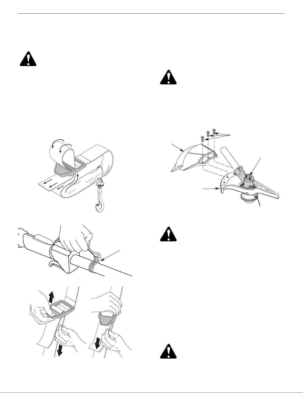
E9
SECCIÓN 3: INTRUCCIONES DE ENSAMBLE
Instale el protector accesorio de corte cuando use la
unidad como recortador de césped.
Instale el protector accesorio de corte en el montaje del
protector insertando tres (3) tornillos en el montaje del
protector. Ajuste bien con un destornillador de vástago
plano (Fig. 7).
REMOCIÓN DEL ACCESORIO DE CORTE E
INSTALACIÓN DE LA CUCHILLA DE CORTE
NOTA: Para facilitar la remoción o la instalación de la
cuchilla de corte o del accesorio de corte,
coloque la unidad sobre el suelo o sobre un
banco de trabajo.
Remoción del protector accesorio de corte
Lea Remoción e Instalación del Protector Accesorio de Corte.
Remoción del accesorio de corte
REMOCIÓN E INSTALACIÓN DEL PROTECTOR
ACCESORIO DE CORTE
Saque el protector accesorio de corte cuando use la
unidad como cortador de malezas
Saque el protector accesorio de corte del montaje del
protector retirando los tres (3) tornillos con un
destornillador de vástago plano (Fig. 7). Guarde las
piezas para usarlas en el futuro.
(3) Tornillos
Protector
accesorio
de corte
Montaje del
protector
Bastidor del
engranaje
INSTALACIÓN DEL ARNÉS
1. Pase la correa a través del centro de la hebilla.
2. Pase la correa sobre la barra transversal y hacia
abajo a través de la ranura de la hebilla (Fig. 4).
3. Coloque el arnés por encima de su cabeza y sobre su
hombro. Abroche en el adaptador de apoyo (Fig. 5).
4. Ajuste la longitud de acuerdo a la medida del
operador. Tire de la orejeta para alargarlo y tire de la
correa para acortarlo (Fig. 6).
Adaptador
de apoyo
ADVERTENCIA: El protector accesorio de
corte NO debe estar instalado cuando use
la unidad con una cuchilla. Saque el
protector accesorio de corte antes de sacar
o instalar la cuchilla.
ADVERTENCIA: El bastidor del engranaje se
calienta mucho con el uso y puede causar
lesiones al operador. Cuando la unidad se
apaga, permanece caliente durante un rato.
No toque el bastidor del engranaje hasta
que se haya enfriado.
ADVERTENCIA: Para evitar graves lesiones
personales, el protector accesorio de corte
DEBE estar instalado en todo momento cuando
use la unidad como recortador de césped.
ADVERTENCIA: Use siempre el arnés para
el hombro cuando use la cuchilla de corte a
fin de evitar graves lesiones personales.
Figure 7
Figure 6
Figure 5
Figure 4
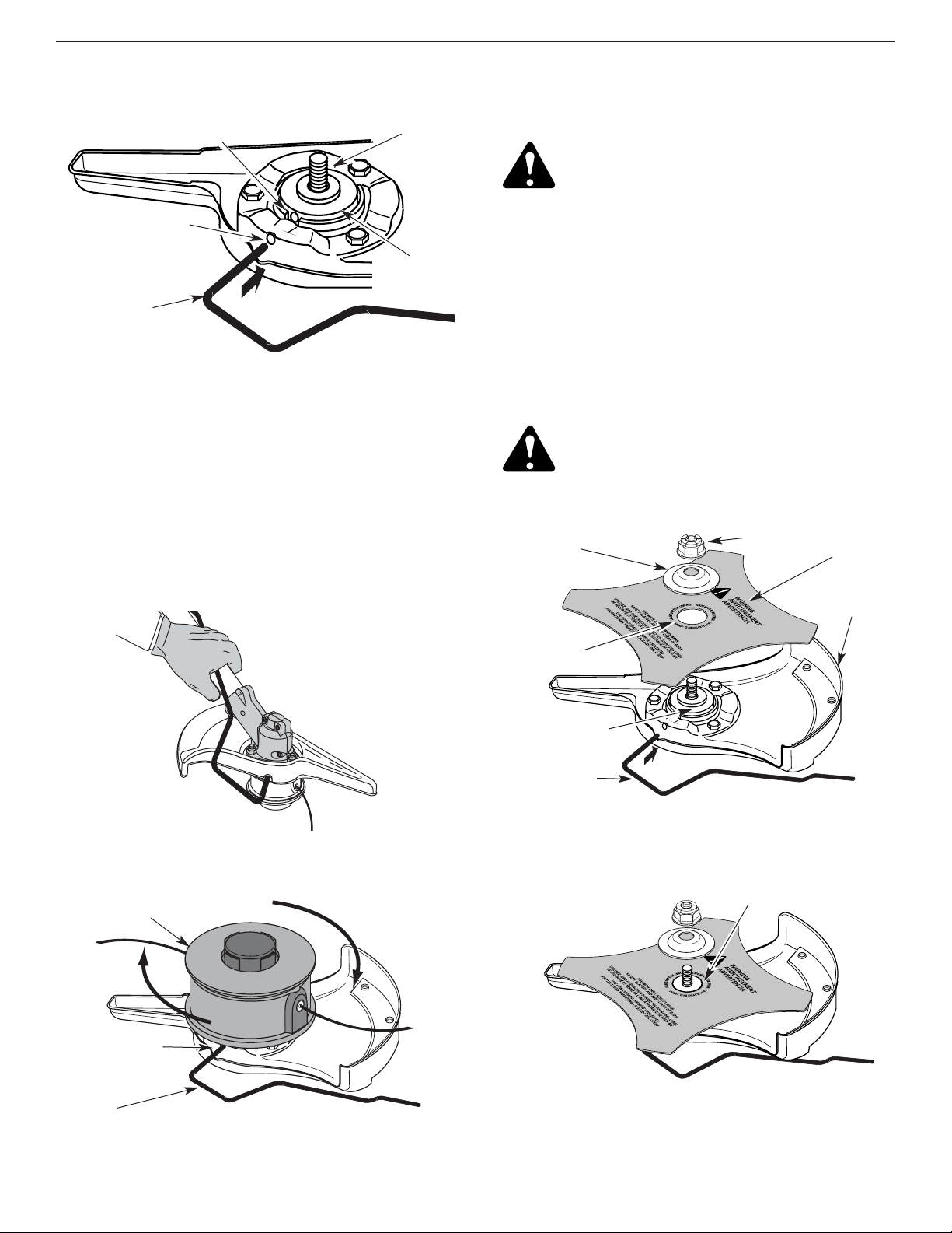
E10
SECCIÓN 3: INTRUCCIONES DE ENSAMBLE
Instalación de la cuchilla de corte
4. Coloque la cuchilla de corte en el buje del eje de
salida (Fig. 11).
5. Verifique que la cuchilla de corte esté centrada en el
estribo de guía y quede plana contra el buje del eje
de salida (Fig. 12).
6. Alinee el orificio del buje del eje con la ranura de la
varilla de cierre e inserte la varilla de cierre en el
orificio del buje (Fig. 8).
7. Coloque el retén de la cuchilla y la tuerca en el eje de
salida. Verifique que la cuchilla esté bien instalada.
Accesorio de corte
Ranura de la
varilla de cierre
Varilla de cierre
Orificio del buje del eje
Ranura de la
varilla de cierre
Buje del eje
de salida
Varilla de
cierre
Eje de salida
1. Alinee el orificio del buje del eje con la ranura de la varilla
de cierre e inserte la varilla de cierre en el orificio del buje
del eje (Fig. 8).
2. Sostenga la varilla de cierre en su lugar junto al brazo
de la unidad (Fig. 9).
3. Mientras sostiene la varilla de cierre, saque el
accesorio de corte girando en sentido horario hacia
afuera del eje de salida (Fig. 10). Guarde el accesorio
de corte para su uso futuro.
NOTA: El retén de la cuchilla debajo del accesorio de corte
se utilizará cuando instale la cuchilla de corte.
Montaje del
protector
Varilla de
cierre
Cuchilla de
corte
Retén de la cuchilla
Tuerca
Buje del eje
de salida
Orificio de guía
Estribo de guía
ADVERTENCIA: Si la cuchilla de corte no
está centrada, la unidad vibrará y la cuchilla
puede desprenderse y salir volando, lo cual
puede causar graves lesiones personales.
ADVERTENCIA: Para evitar graves lesiones
personales, use siempre guantes cuando
maneje o instale la cuchilla.
Figure 12
Figure 11
Figure 10
Figure 9
Figure 8

E11
SECCIÓN 3: INTRUCCIONES DE ENSAMBLE
Accesorio de corte
Varilla de cierre
Instalación del accesorio de corte
5. Alinee el orificio del buje del eje con la ranura de la
varilla de cierre e inserte la varilla de cierre en el
orificio del buje del eje (Fig. 8). Coloque el retén de la
cuchilla en el eje de salida con la superficie plana
contra el buje del eje de salida según se ilustra en la
Fig. 15. Enrosque el accesorio de corte en sentido
antihorario en el eje de salida. Ajuste bien.
NOTA: El retén de la cuchilla debe estar instalado en el
eje de salida en la posición ilustrada para que el
accesorio de corte funcione en forma correcta.
6. Saque la varilla de cierre.
Sentido
horario
Retén de la
cuchilla
Buje del eje
de salida
1/4-1/2 de vuelta
en sentido
antihorario
9. Saque la varilla de cierre de la ranura de la varilla de
cierre.
REMOCIÓN DE LA CUCHILLA DE CORTE E
INSTALACIÓN DEL ACCESORIO DE CORTE
Remoción de la cuchilla de corte
1. Alinee el orificio del buje del eje con la ranura de la
varilla de cierre e inserte la varilla de cierre en el
orificio del buje (Fig. 8).
2. Sostenga la varilla de cierre en su lugar junto al brazo
de la unidad (Fig. 14).
3. Mientras sostiene la varilla de cierre, afloje la tuerca
de la cuchilla girándola en sentido horario con una
llave de casquillo o de boca cerrada de 16 mm (5/8
de pulgada) (Fig. 14).
8. Ajuste la tuerca en sentido antihorario contra la
cuchilla mientras sostiene la varilla de cierre;
• Si usa una llave de torsión y un casquillo de 16 mm
(5/8 de pulgada), ajuste a:
325 - 335 pulgadas • libra,
27 - 28 pies • libra,
37 -38 N•m.
• Si no tiene una llave de torsión, use una llave de boca
cerrada de 5/8 de pulgada o de casquillo, gire la tuerca
hasta que el retén de la cuchilla esté ajustado contra el
buje del eje. Verifique que la cuchilla esté bien
instalada, luego gire la tuerca 1/4 a 1/2 vuelta más en
sentido antihorario (Fig. 13).
4. Saque la tuerca, el retén de la cuchilla y la cuchilla.
Guarde la tuerca y la cuchilla juntas en un lugar
seguro para su uso futuro. Guarde fuera del alcance
de los niños.
7. Instale el protector accesorio de corte. Lea Remoción
e instalación del protector accesorio de corte.
ADVERTENCIA: No afile la cuchilla de corte.
Afilar la cuchilla puede causar que la punta
se desprenda durante el uso. Esto puede
causar graves lesiones personales. Cambie
la cuchilla.
ADVERTENCIA: Para evitar graves lesiones
personales o el daño de la unidad, no
arranque ni use esta unidad con la varilla
de cierre en la ranura de la varilla de cierre.
ADVERTENCIA: Para evitar graves lesiones
personales, el protector accesorio de corte
DEBE estar instalado en todo momento
cuando use la unidad como recortador de
césped.
ADVERTENCIA: Si la cuchilla de corte no
está centrada, la unidad vibrará y la cuchilla
puede desprenderse y salir volando, lo cual
puede causar graves lesiones personales.
Figure 13
Figure 15
Figure 14

E12
PELIGRO: EL LLENAR DEMASIADO EL
CÁRTER PUEDE CAUSAR LESIONES
PERSONALES GRAVES No podemos exagerar
la importancia del control y mantenimiento
del nivel correcto de aceite en el cigüeñal.
Verifique el aceite antes de cada uso y
cámbielo cuando sea necesario según se
indica en la sección de Cambio del aceite.
SECCIÓN 4: INFORMACION DEL ACEITE Y DEL COMBUSIBLE
TIPO DE ACEITE RECOMENDADO
El uso de un aceite del tipo y peso correctos en el cigüeñal
es extremadamente importante. Verifique el aceite antes
de cada uso y cambie el aceite con frecuencia. Si no usa
el aceite correcto, o utiliza aceite sucio, puede causar el
desgaste y falla prematuros del motor.
Use un aceite de buena calidad SAE 30 de API (American
Petroleum Institute) clase de servicio SG, SF, SH.
CARGA DE ACEITE EN EL CARTER DEL CIGÜEÑAL:
USO INICIAL
NOTA: Esta unidad se envía sin carga de aceite. A fin de
evitar el daño de la unidad, cargue aceite en el
cárter del cigüeñal antes de intentar arrancar la
unidad.
Su unidad trae una botella de aceite SAE 30 SF, SG, SH
de 3.4 onzas fluidas (100 ml.) (Fig. 16).
NOTA: Guarde la botella para medir la cantidad correcta
de aceite cuando deba cambiarlo en el futuro.
Lea Cambio de Aceite.
1. Desenrosque la tapa de la botella de aceite y retire el
sello de papel que cubre la apertura. Vuelva a
colocar la tapa. Corte la punta de la boquilla del
embudo (Fig. 16).
2. Coloque la unidad sobre una superficie plana.
3. Saque el tapón de aceite/ varilla de medición del
cigüeñal (Fig. 17).
NOTA: No agregue nunca aceite al combustible o al
tanque de combustible.
5. Limpie todo el aceite que pueda haberse derramado
y vuelva a instalar el tapón del aceite / varilla de
medición.
No podemos exagerar la importancia del control y
mantenimiento del nivel correcto de aceite en el cigüeñal.
Verifique el aceite antes de cada uso y cámbielo cuando
sea necesario según se indica en la sección de Cambio
del aceite.
4. Vierta todo el contenido de la botella de aceite en el
cigüeñal (Fig. 18).
Tapón de relleno
de aceite/ varilla
de medición
Orificio de llenado
de aceite
Orificio de llenado
de aceite
Anillo en “O”
Figure 18
Figure 17
Figure 16

E13
SECCIÓN 4: INFORMACION DEL ACEITE Y DEL COMBUSIBLE
CARGA DE COMBUSTIBLE EN LA UNIDAD
1. Saque la tapa de la gasolina.
2. Coloque el pico del recipiente de gasolina en el
orificio de llenado del tanque de gasolina (Fig. 19) y
llene el tanque.
NOTA: No llene el tanque demasiado.
3. Limpie toda la gasolina que pueda haberse
derramado
4. Vuelva a instalar la tapa de la gasolina.
5. Mueva la unidad por lo menos 30 pies (9.1 m) de la
fuente y sitio de carga antes de arrancar el motor.
NOTA: Elimine la gasolina vieja de acuerdo a los
reglamentos federales, estatales y locales.
TIPO DE COMBUSTIBLE RECOMENDADO
El combustible viejo es la causa principal del mal
funcionamiento de la unidad. Asegúrese de usar
combustible nuevo, limpio y sin plomo.
NOTA: Este es un motor de cuatro ciclos. Para evitar
dañar su unidad, no mezcle el aceite con la
gasolina.
Definición de los combustibles de mezcla
Los combustibles actuales con frecuencia son una
mezcla de gasolina y uno o más oxigenantes como el
etano, el metanol o el MTBE (éter). El combustible con
mezcla de alcohol absorbe agua. Un porcentaje de agua
tan pequeño como el 1% en el combustible puede hacer
que el combustible y el aceite se separen. Se forman
ácidos mientras está guardado. Cuando use
combustible con mezcla de alcohol, use combustible
nuevo (almacenado durante menos de 60 días).
Uso de los combustibles de mezcla
Si decide usar un combustible de mezcla o si su uso es
inevitable, le recomendamos que tome las siguientes
precauciones:
• Use siempre una mezcla fresca de combustible
según lo indica su manual del operador
• Use el aditivo especial de combustible STA-BIL
®
o uno similar
• Drene el tanque y haga funcionar el motor en seco
antes de guardar la unidad
Uso de aditivos en el combustible
El uso de aditivos en el combustible, como el
estabilizador de gasolina STA-BIL®o similar, inhibirá la
corrosión y reducirá la formación de depósitos de goma.
El uso de aditivos puede evitar que se formen depósitos
dañinos en el carburador por hasta ocho (8) meses.
Agregue 0.8 de onza (23 ml.) de aditivo por galón de
combustible de acuerdo a las instrucciones del envase.
No agregue NUNCA los aditivos directamente al tanque
de combustible de la unidad.
Combustible
sin plomo
ADVERTENCIA: La gasolina es muy inflamable
y sus gases pueden explotar si se encienden.
Para evitar graves lesiones personales, pare
siempre el motor y espere que se enfríe antes
de llenar el tanque de combustible. No fume
mientras llena el tanque. Mantenga las chispas
y las llamas fuera del área.
ADVERTENCIA
: Retire la tapa del
combustible lentamente para evitar
lesionarse con el rocío de la gasolina.
ADVERTENCIA : Cargue la gasolina en un
área exterior limpia y bien ventilada. Evite
crear una fuente de encendido del
combustible derramado.
ADVERTENCIA
: No opere nunca la unidad
sin la tapa de la gasolina colocada
firmemente en su lugar.
Figure 19

E14
SECCIÓN 5: INSTRUCCIONES DE ARRANQUE Y APAGADO
INSTRUCCIONES DE ARRANQUE
Arranque en frío:Primer arranque del día o el motor se
quedó sin combustible
ADVERTENCIA:
Use esta unidad sólo en un
área exterior bien ventilada. Los gases de
escape de monóxido de carbono pueden
ser letales en un área cerrada.
1. Verifique el nivel de aceite en el cárter del cigüeñal.
Lea Inspección del Nivel de Aceite.
2. Llene el tanque de combustible con gasolina nueva,
limpia y sin plomo.
3. Coloque el Control de Arranque y Apagado del Motor
en la posición de ARRANQUE (START) [I] (Fig. 20).
ADVERTENCIA: Evite los arranques
accidentales. Colóquese en posición de inicio
cuando tire de la cuerda de arranque
(Fig. 22). El operador y la unidad deben estar
en una posición estable al arrancar la unidad
para evitar graves lesiones personales.
4. Coloque la palanca del obturador en posición de
obturación COMPLETA (FULL) (A) (Fig. 21).
NOTA: Deslice la palanca del obturador directamente
sobre el símbolo adecuado en la calcomanía de
la cubierta del filtro de aire (Fig. 21).
5. Oprima por completo y suelte la bombilla del
cebador lentamente 10 veces. Debe poder sentir y
ver la gasolina en la bombilla (Fig. 21). Si no ha
entrado gasolina en la bombilla, oprima tres veces
más, o hasta que lo haga.
10. Mueva la palanca del obturador a la posición de
MARCHA (RUN) (C)y déjelo funcionar con
regulación máxima durante 30 segundos.
11. Suelte el control del regulador a la posición de
mínima y comience la operación.
NOTA: Si el motor no arranca utilizando estos
procedimientos, repita los pasos 4 a 11
utilizando DOS (2) tirones en la posición de
obturación COMPLETA (FULL) (A).
Nuevo arranque del motor:Motor caliente con combustible
1. Coloque el Control de Arranque y Apagado del Motor
en la posición de ARRANQUE (START) [I] (Fig. 20).
2. Mueva la palanca del obturador a la posición de
PARCIAL (B) (Fig. 21).
3. Oprima por completo y suelte la bombilla del
cebador lentamente 10 veces. Debe poder sentir y
ver la gasolina en la bombilla (Fig. 21). Si no ha
entrado gasolina en la bombilla, oprima tres veces
más, o hasta que lo haga.
4. Oprima el control del regulador a la posición abierta
(regulación máxima).
5. Con la unidad en posición de arranque (Fig. 22), tire
de la cuerda de arranque rápidamente hasta que el
motor arranque.
6. Cuando el motor arranca, mueva la palanca del
obturador a la posición de MARCHA (RUN) (C),
y hágalo funcionar con regulación máxima
durante 30 segundos.
NOTA: Si el motor no arranca con el procedimiento de
nuevo arrranque del motor, vuelva a realizar el
procedimiento de Arranque en Frío.
INSTRUCCIONES DE APAGADO
1. Saque su mano del control del regulador (Fig. 22).
Deje que el motor funcione en mínima.
2. Para apagar el motor, coloque el Control de
Arranque y Apagado del Motor en la posición de
APAGADO (STOP) [O] (Fig. 20).
6. Oprima el control del regulador hacia la posición
abierta (regulación plena).
7. Con la unidad en posición de arranque, tire de la
cuerda de arranque rápidamente cinco veces en la
posición de obturación COMPLETA (FULL) (A). Si
el motor intenta arrancar antes del quinto tirón,
proceda con el paso 8.
8. Mueva la palanca del obturador a la posición
de obturación PARCIAL (B) (Fig. 21).
NOTA: El motor no funcionará en la posición de
obturación COMPLETA (A)
.
9. Tire de la cuerda de arranque de 1 a 3 veces hasta
que el motor arranque. Déjelo funcionar de 15 a 30
segundos. Si la unidad no arranca, vuelva al paso 4.
Bombilla
del cebador
Palanca del
obturador
Figure 22
Control del regulador
Cuerda de
arranque
Figure 21
Figure 20
Arranque/Encendido (I)
Parado/
Apagado (O)
Traba del
regulador
Control del
regulador

E15
SECCIÓN 6: INSTRUCCIONES DE OPERACIóN
Para recortar bordes mientras usa el accesorio de corte
de cabeza de línea con modelos EZ-Link™, trabe el
botón de desconexión en el orificio lateral de 90° o en
el orificio lateral de 180° (Fig. 25).
3. Gire la perilla en sentido horario para ajustarla (Fig. 25).
OPERACION DEL SISTEMA EZ-Link™
El sistema EZ-Link™ le permite el uso de estos
accesorios optativos.
Soplador/Aspirador . . . . . . . . . . . . . . . . . . . . . . . BV720r
Cultivador . . . . . . . . . . . . . . . . . . . . . . . . . . . . . . GC720r
Recortador de bordes . . . . . . . . . . . . . . . . . . . . . LE720r
Recortador de setos . . . . . . . . . . . . . . . . . . . . . . HS720r
Lanzanieves . . . . . . . . . . . . . . . . . . . . . . . . . . . . . ST720r
Recortador de eje recto . . . . . . . . . . . . . . . . . . . SS725r
Podador de árboles . . . . . . . . . . . . . . . . . . . . . . . TP720r
Soplador Turbo . . . . . . . . . . . . . . . . . . . . . . . . . . TB720r
Remoción del accesorio de corte u otros accesorios
1. Gire la perilla en sentido antihorario para aflojarla
(Fig. 23).
2. Opima y sostenga el botón de desconexión (Fig. 23).
3. Mientras sostiene el bastidor del eje superior con
firmeza, tire del accesorio de corte o accesorio en
línea recta fuera del acoplador EZ-Link™.
Instalación del accesorio de corte u otros accesorios
NOTA: Para facilitar la instalación o remoción de los
accesorios, coloque la unidad sobre el suelo o
sobre un banco de trabajo.
1. Gire la perilla en sentido antihorario para aflojarla
(Fig. 23).
2. Mientras sostiene el accesorio con firmeza, empújelo
en línea recta en el acoplador EZ-Link™ (Fig. 24).
NOTA: La alineación del botón de desconexión con el
hueco de guía facilitará la instalación (Fig. 23).
Acoplador EZ-Link™
Botón de desconexión
Hueco de
guía
Perilla
Orificio primario
Bastidor del
eje superior
Bastidor del
eje inferior
Botón de desconexión
Orificio lateral 90˚
Orificio lateral
180˚
Perilla
Acoplador EZ-Link™
Figure 25
Figure 24
Figure 23
PRECAUCION: Trabe el botón de
desconexión en el orificio primario y ajuste
bien la perilla antes de operar esta unidad.
PRECAUCION: El accesorio de corte y los
accesorios con el sistema EZ-Link™ deben
ser usados en el orificio primario a menos
que se indique lo contrario en el manual
del operador del accesorio. El usar el
orificio incorrecto puede conducir a
lesiones personales o daño de la unidad.
ADVERTENCIA: Lea y comprenda el
manual del operador de los accesorios
antes de su operación.
ADVERTENCIA: Para evitar graves lesiones
personales, apague la unidad antes de
sacar o instalar accesorios.
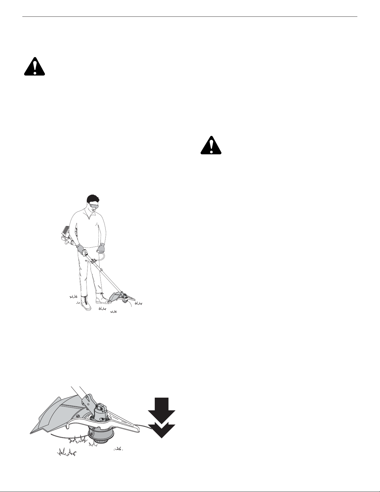
E16
Figure 26
SECCIÓN 6: INSTRUCCIONES DE OPERACIóN
COMO SOSTENER EL RECORTADOR
ADVERTENCIA:
Use siempre protección
para sus ojos, audición, pies y cuerpo para
reducir el riesgo de una lesión al operar
esta unidad.
Antes de operar esta unidad, párese en posición de
operación (Fig. 26). Verifique lo siguiente:
• El operador tiene protección ocular y ropa adecuada.
• El brazo derecho está levemente doblado, y la mano
está sosteniendo el mango del eje.
• El brazo izquierdo está recto, y la mano está
sosteniendo la manija.
• La unidad está debajo del nivel de la cintura.
• El accesorio de corte está paralelo al suelo y hace fácil
contacto con la vegetación que va a ser cortada sin
que el operador tenga que inclinarse.
Una vez que usted esté en la posición de funcionamiento,
enganche la correa para el hombro a la unidad.
AJUSTE DE LA LONGITUD DE LA LINEA DE CORTE
El accesorio de corte Bump Head™ le permite soltar
línea de corte sin apagar el motor. Para soltar más línea,
golpee suavemente el accesorio de corte contra el suelo
(Fig. 27) mientras opera el recortador a alta velocidad.
NOTA: Mantenga siempre la línea de corte
completamente extendida. Es más difícil soltar
línea al acortarse la línea de corte.
Cada vez que se golpea la cabeza, se suelta alrededor
de 25,4 mm (1 pulgada) de línea de corte. La cuchilla en
la protección del accesorio de corte detendrá la línea en
la longitud correcta si se suelta demasiada línea.
Para obtener mejores resultados, golpee la Bump Head™
sobre terreno limpio o tierra dura. Si intenta soltar la línea
sobre el césped alto, el motor podrá ahogarse. Mantenga
siempre la línea de corte completamente extendida. Es
más difícil soltar línea al acortarse la línea de corte.
NOTA: No apoye la Bump Head™ sobre el suelo
mientras la unidad esté en funcionamiento.
PRECAUCIÓN: No quite ni altere el
montaje de la cuchilla de corte de línea. La
longitud excesiva de la línea hará recalentar
la unidad. Eso puede ocasionar lesiones
personales graves o causarle daños a la
unidad. La línea puede cortarse por:
La línea puede cortarse por:
• Enredarse con un objeto extraño
• Fatiga normal de la línea
• Intentar cortar hierbas gruesas y leñosas
• Forzar la línea en objetos como paredes o postes de
cercos
CONSEJOS PARA OBTENER MEJORES
RESULTADOS AL RECORT AR
• Para mejores resultados que recortan, operar la unidad
en válvula de admisión repleta.
• El ángulo correcto para ubicar el accesorio de corte
es paralelo al suelo.
• No fuerce el accesorio de corte. Permita que la punta
de la línea realice el corte (en especial a lo largo de
paredes). Si corta con más de la punta reducirá la
eficacia del corte y puede sobrecargar el motor.
• Corte césped de más de 200 mm (8 pulgadas) trabajando
de arriba hacia abajo en pequeños incrementos para evitar
el desgaste prematuro de la línea y el arrastre del motor.
• Corte de izquierda a derecha siempre que sea posible.
Cortar hacia la derecha mejora la eficiencia de la
unidad. Los recortes salen arrojados en sentido
contrario al operador.
•Mueva lentamente el recortador dentro y fuera del área
de corte a la altura deseada. Realice movimientos ya
sea de adelante hacia atrás y viceversa, o de lado a
lado. El corte en longitudes más cortas produce
mejores resultados.
• Recorte únicamente cuando el pasto y las hierbas
estén secas.
• La vida de su línea de corte depende de:
• Seguir todas las técnicas de corte indicadas
anteriormente
• El tipo de vegetación que corte
• El lugar donde se corta
Por ejemplo, la línea se desgastará más rápido cuando corte
contra un muro que cuando corte alrededor de un árbol.
Figure 27

E17
SECCIÓN 6: INSTRUCCIONES DE OPERACIóN
RECORTE DECORATIVO
El recorte decorativo se realiza eliminando toda la
vegetación de alrededor de los árboles, postes, cercos, etc.
Gire toda la unidad a modo de que el accesorio de corte
se ubique a un ángulo de 30° con el suelo (Fig 28).
USO DE LA CUCHILLA DE CORTE
Antes de operar la unidad con la cuchilla de corte,
párese en posición de corte (Fig. 29). Lea Cómo sostener
el Recortador.
Consejos para el uso de la cuchilla de corte
Para establecer un procedimiento rítmico de corte:
• Fije los pies con firmeza, cómodamente aparte.
• Lleve el motor a plena regulación antes de penetrar el
material a cortar. La cuchilla tiene su máxima
capacidad de corte a plena regulación y también es
menos probable que se adhiera, se trabe o cause el
impulso de la cuchilla, lo cual puede causar graves
lesiones personales al operador o a otros.
•Corte girando la parte superior de su cuerpo de
izquierda a derecha.
• Suelte siempre el gatillo del regulador y espere que el
motor vuelva a marcha lenta cuando no esté cortando.
•Cuando termine la labor, desabroche siempre la
unidad antes de quitarse el arnés.
• Mueva la unidad en la dirección opuesta en que gira la
cuchilla, con lo cual logrará una mejor acción de corte.
• Avance al área siguiente a cortar después de la
maniobra de retorno, y vuelva a fijar los pies.
• La cuchilla de corte está diseñada con un segundo
borde de corte, el cual puede ser utilizado retirando
la cuchilla, dándola vuelta y volviendo a instalarla.
Para reducir la posibilidad de que se enrede material en
la cuchilla, siga estos pasos:
• Corte a plena regulación.
•Mueva la unidad de su izquierda a derecha hacia el
material que va a cortar (Fig. 30).
• En el movimiento de retorno, evite tocar el material
que acaba de cortar.
Figure 28
ADVERTENCIA: No limpie el material con el
motor en marcha ni con la cuchilla girando.
Para evitar graves lesiones personales,
apague el motor. Espere que la cuchilla se
detenga antes de sacar el material envuelto
alrededor del eje de la cuchilla.
ADVERTENCIA: No afile la cuchilla de
corte. Si afila la cuchilla, la punta puede
desprenderse durante su uso. Esto puede
causar graves lesiones personales a usted
mismo o a los demás. Cambie la cuchilla.
ADVERTENCIA: La cuchilla continúa girando
luego de apagar el motor. La cuchilla en
deslizamiento puede causarle graves cortes
si lo toca en forma accidental.
ADVERTENCIA: Cuando la cuchilla giratoria
hace contacto con un objeto que no corta
de inmediato, puede ocurrir el impulso de la
cuchilla. El impulso de la cuchilla puede ser
lo suficientemente violento como para hacer
que la unidad y/o el operador sean
impulsados en cualquier dirección, y
posiblemente perder el control de la unidad.
El impulso de la cuchilla puede ocurrir si la
cuchilla se tropieza, se traba o se atora. Es
más posible que esto ocurra en áreas donde
es difícil ver el material que está cortando.
ADVERTENCIA: No use la cuchilla de corte
para recortar bordes ni como un recortador
de bordes, puede causarle graves lesiones
personales a usted o a los demás
ADVERTENCIA: Use siempre protección para
sus ojos, audición, pies y cuerpo para reducir
el riesgo de una lesión al operar esta unidad.
Figure 30
Figure 29

E18
ADVERTENCIA: Para evitar lesiones personales
graves, nunca realice mantenimiento ni
reparaciones con la unidad funcionando.
Realice siempre el mantenimiento y las
reparaciones con la unidad fría. Desconecte el
cable de la bujía de encendido para cerciorarse
de que la unidad no arrancará.
NOTA: Algunos procedimientos de mantenimiento
pueden requerir el uso de herramientas o
habilidades especiales. Si no está seguro acerca
de estos procedimientos, lleve su unidad a un
establecimiento de reparación, persona o
distribuidor de servicio autorizado que arregle
motores para uso fuera de la carretera.
PROGRAMA DE MANTENIMIENTO
Estos procedimientos requeridos para el mantenimiento
deben ser realizados con la frecuencia indicada en la
tabla. Deben ser incluidos como parte de toda puesta a
punto de cada temporada.
NOTA: El mantenimiento, la sustitución o arreglo de
dispositivos para el control de emisiones y
sistemas pueden ser hechos por cualquier
establecimiento de reparación, persona o
proveedor de servicio autorizado que arregle
motores para uso fuera de la carretera.
SECCIÓN 7: INSTRUCCIONES DE MANTENIMIENTO Y REPARACIóN
FRECUENCIA MANTENIMIENTO REQUERIDO CONSULTE
Antes de arrancar el motor
Llene el tanque de combustible con combustible nuevo
Inspeccione el aceite
Page 13
Page 20
Cada 10 horas Limpie y vuelva a aceitar el filtro de aire Page 22
Primer cambio a las 10 horas
Cada 25 horass en lo sucesivo
Cada 25 horas
Cambie el aceite
Cambie el aceite
Limpie el amortiguador de chispas
Page 21
Page 21
Page 25
10 horas en un motor nuevo
Cada 25 horas
Cada 25 horas
Verifique la separación entre el brazo oscilante y la válvula y ajuste
Verifique la separación entre el brazo oscilante y la válvula y ajuste
Verifique la condición y separación de la bujía de encendido
Page 24
Page 24
Page 25
2. Saque el carrete interior de la bobina exterior (Fig. 31).
3. Saque el resorte del carrete interior (Fig. 31).
4. Use un paño limpio para limpiar el carrete interior, el
resorte, el eje y la bobina exterior (Fig. 32).
5. Verifique el desgaste de los dientes de posición del carrete
interior y bobina exterior (Fig. 33). Si es necesario, saque la
rebaba o cambie el carrete y la bobina.
Botón de tope
Perno
Carrete interior
Bobina exterior
Resorte
Dientes de posición
INSTALACION DE LA LINEA
Esta sección cubre la instalación de la línea SplitLine™ y
de la línea individual regular.
Use siempre la línea de repuestos de 2,41 mm (0,095
pulg.) de Genuine Factory Parts™. Una línea que no sea la
indicada puede causar que el motor se recaliente o falle.
ADVERTENCIA: No use nunca línea reforzada
con metal, alambre, cadena ni soga, etc. Estos
elementos pueden desprenderse y convertirse
en un proyectil peligroso
.
Existen dos métodos para cambiar la línea de corte.
• Bobine el carrete interior con línea nueva.
• Instale un carrete interior prebobinado
Bobinado del carrete interior existente
1. Sostenga la bobina exterior con una mano y
desenrosque el botón de tope en sentido antihorario
(Fig. 31). Inspeccione el perno de adentro del botón
de tope para verificar que se mueva con libertad.
Cambie el botón de tope si está dañado.
Figure 33
Figure 32
Figure 31
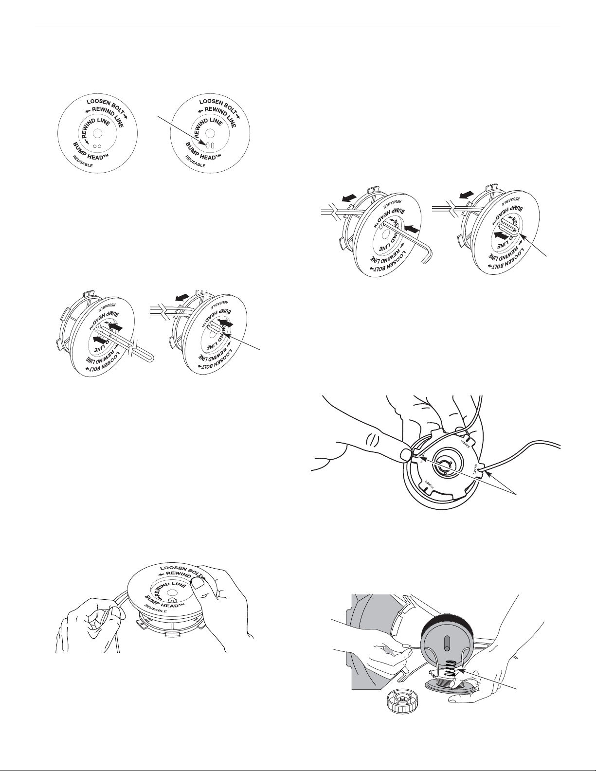
E19
SECCIÓN 7: INSTRUCCIONES DE MANTENIMIENTO Y REPARACIóN
INSTALACIóN DE LA LINEA A INDIVIDUAL
Lea la instalación de la línea SplitLine™ en el paso 8
6. Tome aproximadamente 40 pies (12.2 m) de nueva
línea de corte, enlácela en dos longitudes iguales.
Inserte cada extremo de la línea a través de uno de
los dos orificios del carrete interior (Fig. 35). Pase la
línea a través del carrete interior de modo que el lazo
sea lo más pequeño posible.
7. Bobine las líneas en capas parejas y ajustadas sobre
el carrete (Fig. 36). Bobine la línea en la dirección
indicada en el carrete interior. Coloque su dedo
índice entre las dos líneas para evitar que se
superpongan. No superponga los extremos de la
línea. Proceda al paso 11.
Instalación de la línea SplitLine™
8. Tome aproximadamente 20 pies (6.1 m) de nueva
línea de corte. Inserte un extremo de la línea a través
de uno de los orificios del carrete interior (Fig. 37).
Pase la línea a través del carrete interior hasta que
queden sólo 4 pulgadas fuera.
9. Inserte el extremo de la línea en el orificio abierto del
carrete interior y tire de la línea en forma ajustada a fin
de que el lazo sea lo más pequeño posible (Fig. 37).
10. Antes de bobinar, separe la línea alrededor de 6
pulgadas.
11. Bobine la línea en capas parejas y ajustadas en la
dirección indicada en el carrete interior.
NOTA: Si no bobina la línea en la dirección indicada, el
accesorio de corte no funcionará en forma correcta.
12. Inserte los extremos de la línea en las dos ranuras de
fijación (Fig. 38).
13. Inserte los extremos de la línea a través de los ojalillos
de la bobina exterior y coloque el carrete interior con
el resorte dentro de la bobina exterior (Fig. 39). Empuje
el carrete interior y la bobina exterior entre sí. Mientras
sostiene el carrete interior y la bobina exterior, tome
los extremos y tire con firmeza para soltar la línea de
las ranuras de fijación de la bobina.
Para usar con SplitLine™
o línea individual
Para usar SÓLO con
línea individual
Orificios
ranurados
Lazo
Resorte
Ranuras de Fijación
Lazo
NOTA: La línea SplitLine™ sólo puede usarse con el
carrete interior con los orificios ranurados. La línea
individual puede usarse en cualquier tipo de
carrete interior. Use la Figura 34 para identificar el
carrete interior que usted tiene.
NOTA: Use siempre la longitud correcta de línea cuando
instale la línea de corte en la unidad. La línea
puede no soltarse en forma adecuada si es
demasiado larga.
NOTA: El resorte debe estar ensamblado en el carrete
interior antes de volver a ensamblar el accesorio
de corte.
14. Sostenga el carrete interior en su lugar e instale el
botón de tope girándolo en sentido horario. Ajuste bien.
Figure 39
Figure 38
Figure 37
Figure 36
Figure 35
Figure 34

E20
SECCIÓN 7: INSTRUCCIONES DE MANTENIMIENTO Y REPARACIóN
INSPECCION DEL NIVEL DE ACEITE
No podemos exagerar la importancia de verificar y
mantener el nivel correcto de aceite en el cárter del
cigüeñal. Inspeccione el nivel de aceite antes de cada uso:
1. Apague el motor y permita que el aceite drene
dentro del cárter del cigüeñal.
2. Coloque la unidad sobre una superficie plana y nivelada
para obtener una lectura correcta del nivel de aceite.
3. Mantenga la suciedad, recortes de césped, etc. fuera
del motor. Limpie el área alrededor del tapón de relleno
de aceite / varilla de medición antes de retirarlo.
4. Retire el tapón de relleno de aceite / varilla de
medición y seque el aceite. Vuelva a insertarlo
completamente hacia adentro.
5. Retire el tapón de relleno de aceite / varilla de medición e
inspeccione el nivel del aceite. El aceite debe llegar hasta
la parte superior de la varilla de medición (Fig. 40).
Parte superior de la
varilla de medición
Anillo en O
Tapón de relleno de aceite
/ varilla de medición
tapón de relleno de
aceite / varilla de
medición
Orificio de
llenado de aceite
Anillo en O
Lleno
Agregue 1.4-1.5
Onzas
(41-44 ml)
6. Si el nivel está bajo, agregue una pequeña cantidad de
aceite en el orificio de llenado de aceite y vuelva a
medir. Repita hasta que el nivel de aceite llegue hasta
la parte superior de la varilla de medición
.
NOTA: No llene demasiado la unidad.
NOTA: Verifique que el anillo en O esté en su lugar en el
tapón de relleno de aceite / varilla de medición
cuando mida y cambie el aceite (Fig. 41).
PRECAUCION: Para evitar un desgaste
excesivo del motor y el daño de la unidad,
mantenga siempre el nivel de aceite
correcto en el cárter del cigüeñal. No opere
nunca la unidad con el aceite debajo del
extremo inferior de la varilla de medición.
Figure 41
Figure 40
INSTALACIÓN DE UN CARRETE
PREBOBINADO
1. Sostenga la bobina exterior con una mano y
desenrosque el botón de tope en sentido antihorario
(Fig. 31). Inspeccione el perno dentro del botón de
tope para verificar que se mueva con libertad.
Cambie el botón de tope si está dañado.
2. Saque el carrete interior viejo de la bobina exterior
(Fig. 31).
3. Saque el resorte del carrete interior viejo (Fig. 31).
4. Coloque el resorte en el carrete interior nuevo.
NOTA: El resorte debe estar ensamblado en el carrete
interior antes de volver a instalar el accesorio de
corte.
5. Inserte los extremos de la línea en los ojalillos de la
bobina exterior (Fig. 39).
6. Coloque el nuevo carrete interior dentro de la bobina
exterior. Empuje el carrete interior y la bobina exterior
entre sí. Mientras sostiene el carrete interior y la bobina
exterior, tome los extremos y tire con firmeza para
soltar la línea de las ranuras de retención de la bobina.
7. Sostenga el carrete interior en su lugar e instale el
botón de tope girándolo en sentido horario. Ajuste bien.
Piezas de repuesto
Lea Piezas y Accesorios de Repuesto.

E21
SECCIÓN 7: INSTRUCCIONES DE MANTENIMIENTO Y REPARACIóN
CAMBIO DEL ACEITE
En un motor nuevo, cambie el aceite después de las 10
primeras horas de operación. Cambie el aceite mientras
el motor aún está caliente. El aceite fluirá con libertad y
llevará más impurezas.
1. Desenchufe el manguito de la bujía de encendido
para eliminar el arranque.
2. Retire el tapón de relleno de aceite / varilla de medición
.
3. Vierta el aceite fuera del orificio de llenado de aceite
en un recipiente inclinando la unidad hasta una
posición vertical (Fig. 42). Deje suficiente tiempo
como para completar el drenaje.
Nivel de
llenado
4. Seque todo el aceite residual de la unidad y limpie
todo el aceite que pueda haberse derramado.
Elimine todo el aceite de acuerdo con las normas
federales, estatales y locales.
5. Vuelva a cargar el cárter del cigüeñal con 3.4 onzas
fluidas (100 ml) de aceite SAE 30 SF, SG, SH.
NOTA: Use la botella y la boquilla que guardó del uso
inicial para medir la cantidad correcta. El nivel de
3.4 onzas (100 ml.) está aproximadamente en la
parte superior de la etiqueta de la botella
(Fig. 43). Mida el nivel con la varilla de medición.
Si el nivel está bajo, agregue una pequeña
cantidad de aceite y vuelva a medir (Fig. 43). No
lo llene demasiado.
6. Vuelva a colocar el tapón de relleno de aceite / varilla
de medición.
7. Vuelva a conectar el manguito de la bujía de encendido.
Figure 43
Figure 42
PRECAUCION: Use guantes para evitar
sufrir lesiones cuando maneje la unidad.

E22
SECCIÓN 7: INSTRUCCIONES DE MANTENIMIENTO Y REPARACIóN
AJUSTE DEL CARBURADOR
La velocidad lenta del motor puede ser ajustada por la
cubierta del silenciador / filtro de aire (Fig. 49).
NOTA: Los ajustes realizados sin cuidado pueden dañar
seriamente su unidad. Los ajustes del
carburador deben ser realizados por un
proveedor de servicio autorizado.
VInspección del Combustible
En general, el combustible viejo es el motivo principal
para que la unidad no funcione en forma adecuada.
Drene y vuelva a llenar el tanque con combustible
nuevo, limpio y sin plomo antes de hacer ningún ajuste.
Consulte la Información acerca del Aceite y
Combustible.
MANTENIMIENTO DEL FILTRO DE AIRE
Limpieza del filtro de aire
Limpie y vuelva a aceitar el filtro de aire cada 10 horas
de operación. Es un elemento cuyo mantenimiento es
importante. Si no realiza el mantenimiento del filtro de
aire, su garantía será ANULADA.
1. Abra la cubierta del filtro de aire. Empuje hacia
adentro la orejeta del lado derecho de la cubierta, y
extraiga la cubierta del filtro de aire hacia afuera y
hacia la izquierda (Fig. 44).
NOTA: Es posible que deba retirar la tapa de
combustible para poder retirar por completo la
cubierta del filtro de aire.
2. Retire el filtro de aire (Fig. 44).
3. Lave el filtro con agua y detergente (Fig. 45).
Enjuague bien el filtro y déjelo secar.
4. Aplique suficiente aceite limpio de motor SAE 30
para recubrir ligeramente el filtro (Fig. 46).
Filtro de aire
Cubierta del
filtro de aire
Orejeta
5. Apriete el filtro para esparcir y retirar el exceso de
aceite (Fig. 47).
Ranura de la
placa posterior
Ranuras
6. Vuelva a colocar el filtro (Fig. 48).
NOTA: Si opera la unidad sin el filtro de aire, su garantía
será ANULADA.
7. Vuelva a instalar la cubierta del filtro de aire. Coloque
los ganchos del lado izquierdo de la cubierta del
filtro de aire en las ranuras del lado izquierdo de la
placa posterior (Fig. 48).
NOTA: Puede ser necesario que retire la tapa del
combustible para volver a instalar la cubierta del
filtro de aire.
8. Mueva la cubierta hacia la derecha hasta que la
orejeta del filtro de aire calce en su lugar en la ranura
de la placa posterior (Fig. 44 & 48).
9. Vuelva a colocar la tapa del combustible, si es que la
había retirado.
Placa posterior
Figure 48
Figure 45
Figure 44
Figure 47Figure 46
ADVERTENCIA: Para evitar graves lesiones
personales, apague siempre su recortador y
espere que se enfríe antes de limpiarlo o
realizar todo tipo de mantenimiento.

E23
Limpie el filtro de aire
La condición del filtro de aire es importante para la
operación de la unidad. Un filtro de aire sucio limitará el
flujo de aire y cambiará la mezcla de combustible y aire.
Esto con frecuencia se confunde con un carburador mal
ajustado. Verifique la condición del filtro de aire antes de
ajustar el tornillo de marcha en vacío. Consulte
Mantenimiento del Filtro de Aire.
Ajuste para marcha en vacío
ADVERTENCIA: El accesorio de corte puede
estar girando durante los ajustes para marcha
en vacío. Use ropa que lo proteja y cumpla con
todas las instrucciones de seguridad para
prevenir graves lesiones personales.
después de inspeccionar el combustible y limpiar el filtro de
aire el motor aún no funciona en mínima, ajuste el tornillo de
velocidad mínima según se indica a continuación.
1. Arranque el motor y déjelo funcionar en marcha alta
durante un minuto para calentarlo. Lea las
Instrucciones de arranque y apagado.
2. Suelte el gatillo del regulador y deje que el motor
funcione en marcha en vacío. Si el motor se para, inserte
un pequeño destornillador Phillips o de vástago plano en
el orificio de la cubierta del silenciador / filtro de aire
(Fig. 49). Gire el tornillo de marcha en vacío en sentido
horario, de a 1/8 de vuelta por vez (según sea
necesario) hasta que el motor funciona marcha en vacío.
3. Si parece que el motor está funcionando demasiado
rápido, gire el calibrador de velocidad de marcha en
vacío hacia la izquierda 1/8 de giro a la vez (como
sea necesario) para reducir la velocidad.
La inspección del combustible, la limpieza del filtro de
aire y el ajuste del tornillo de marcha en vacío deben
resolver la mayoría de los problemas del motor. De no
ser así y si:
• El motor no funciona en marcha en vacío
• El motor fluctúa o se para al acelerar
• Existe una pérdida de fuerza motriz
Lleve el carburador a un proveedor de servicio
autorizado para que lo ajuste.
ADVERTENCIA: Al apagar la unidad,
asegúrese de que el accesorio de corte se
haya detenido antes de apoyar la unidad
para prevenir graves lesiones personales.
SECCIÓN 7: INSTRUCCIONES DE MANTENIMIENTO Y REPARACIóN
Saque los
tornillos
Cubierta del
motor
Cubierta del
Motor
Silenciador
Vista superior del motor
2. Quite los dos (2) Tornillos de encima de la tapa del motor
con un destornillador de pala o Torx #25 (Fig. 51).
HUELGO DEL BRAZO OSCILANTE
Esto requiere el desarmado del motor. Si usted siente que
no está seguro o que no está calificado como para realizar
esto, lleve la unidad a un centro de servicio autorizado.
NOTA: Inspeccione el huelgo de la válvula del brazo
oscilante con una galga después de las primeras
10 horas de operación y luego cada 25 horas de
operación en lo sucesivo.
• El motor debe estar frío cuando verifique o ajuste el
huelgo de la válvula.
• Esta tarea debe ser realizada en interiores, en un
área limpia y libre de polvo.
1. Retire la cubierta del silenciador presionando la
esquina con un destornillador de vástago plano
(Fig. 50). Deslice las muescas a los lados de la
cubierta del silenciador sobre las orejetas de la
cubierta del motor y retire.
Orejeta
Orejeta
Muescas
Muesca y
Orejeta
Tornillo de ajuste de mínima
Figure 51
Figure 50
Figure 49

E24
SECCIÓN 7: INSTRUCCIONES DE MANTENIMIENTO Y REPARACIóN
4. Desconecte el cable de la bujía de encendido.
5. Limpie la suciedad de alrededor de la bujía de
encendido. Saque la bujía de encendido de la
cabeza del cilindro girando un casquillo de 5/8
pulgadas en sentido antihorario.
6. Saque la cubierta del motor (Fig. 51).
7. Limpie la suciedad de alrededor de la cubierta del brazo
oscilante. Saque el tornillo que sostiene la cubierta del
brazo oscilante con un destornillador grande de vástago
plano o con una broca Torx T-25 (Fig. 53). Saque la
cubierta y la junta del brazo oscilante.
3. Saque el tornillo que está detrás de la cubierta del
motor (Fig. 52).
8. Tire lentamente de la cuerda de arranque para traer el
pistón hacia la parte superior de su recorrido (conocido
como punto muerto superior). Verifique que:
• El pistón se encuentre en la parte superior de su
recorrido mientras mira dentro del orificio de la bujía
de encendido (Fig. 53).
• Ambos brazos oscilantes se mueven con libertad, y
ambas válvulas están cerradas
De no ser así, repita este paso.
9. Deslice la galga entre el brazo oscilante y el resorte
de retorno de la válvula. Mida el huelgo entre el
vástago de la válvula y el brazo oscilante (Fig. 54).
Realice esto en las válvulas de entrada y de escape
El huelgo recomendado para las válvulas de entrada y
de escape es .003 – .006 pulgadas (.076 – 0.152 mm).
Use un calibrador regular de automóvil de .005 pulgadas
(0.127 mm). El calibrador debe deslizarse entre el
balancín y el vástago de la válvula con una ligera
cantidad de resistencia, sin doblarse (Fig. 54).
10. Si el huelgo no se encuentra dentro de las
especificaciones:
a. Gire la tuerca de ajuste con una llave de 5/16
pulgadas (8 mm) o una guía de tuercas (Fig. 55).
• Para incrementar el huelgo, gire la tuerca de
ajuste en sentido antihorario.
• Para reducir el huelgo, gire la tuerca de ajuste en
sentido horario.
b.Vuelva a inspeccionar ambos huelgos, y ajuste si es
necesario.
11. Vuelva a instalar la cubierta del brazo oscilante
utilizando una nueva junta. Ajuste el tornillo a 20–30
pulgadas•libra (2.2–3.4 N•m).
12. Vuelva a instalar la cubierta del motor. Verifique la
alineación de la cubierta antes de ajustar los
tornillos. Ajuste los tornillos.
13. Vuelva a colocar la cubierta del silenciador. Deslice
las muescas a los lados de la cubierta del silenciador
sobre las orejetas de la cubierta del motor y
enganche en su lugar (Fig. 50).
14. Inspeccione la bujía de encendido y vuelva a instalar.
Lea Cambio de la Bujía de encendido.
15. Vuelva a colocar el cable de la bujía de encendido.
Cubierta del brazo
oscilante
Tornillo
Orificio de la
bujía de
encendido
ENTRADA
ESCAPE
Brazos
oscilantes
Galga
Tuercas de ajuste
Calibrador
Tuerca de ajuste
Balancín
.003–.006 pulg.
(.076–0.152 mm)
Vástago de la válvula
Figure 54
Figure 53
Figure 52
Figure 55

E25
SECCIÓN 7: INSTRUCCIONES DE MANTENIMIENTO Y REPARACIóN
CAMBIO DE LA BUJIA DE ENCENDIDO
Use una bujía de encendido 180852 (o similar). La
separación correcta es de 0.025 pulgadas (0.655 mm).
Retire la bujía luego de cada 25 horas de operación e
inspeccione su estado.
1. Detenga el motor y permita que se enfríe. Agarre la
tapa del cable de la bujía firmemente y hálelo.
2. Limpie alrededor de la bujía de encendido. Saque la
bujía de encendido de la cabeza del cilindro girando
una llave de casquillo de 5/8 de pulgada en sentido
antihorario.
3. Cambie toda bujía partida, inundada o sucia. Fije la
separación de aire a 0.025 pulgadas (0.655 mm)
utilizando un calibrador (Fig. 56).
PRECAUCIÓN: No limpie con chorro de
arena, ni raspe o limpie los electrodos. El
motor podría dañarse si penetran pequeñas
partículas en el cilindro.
4. Instale una bujía de encendido con la separación
correcta en la cabeza del cilindro. Ajuste girando la
llave de casquillo de 5/8 pulg. en sentido horario
hasta que esté ajustada sin huelgo.
Si usa una llave de torsión, ajuste a:
110-120 pulg.•libras (12.3-13.5 N•m).
No ajuste demasiado.
0.025 pulg.
(0.655 mm)
Figure 56
Silenciador
Pantalla del amortiguador
de chispas
Cubierta del
amortiguador de
chispas
Tornillo
Orejeta
Ranura
MANTENIMIENTO DEL AMORTIGUADOR DE CHISPAS
1. Saque la cubierta del amortiguador de chispas. Lea
Huelgo del brazo oscilante.
2. Con un destornillador de vástago plano o broca Torx
T20, saque el tornillo que conecta la cubierta del
amortiguador de chispas al silenciador (Fig. 57).
3. Saque la orejeta de la cubierta del amortiguador de
chispas fuera del silenciador. Retire la cubierta del
amortiguador de chispas.
4. Saque la pantalla del amortiguador de chispas de la
cubierta del amortiguador de chispas.
5. Limpie la pantalla del amortiguador de chispas con
un cepillo de alambre, o cámbiela.
6. Vuelva a instalar la pantalla del amortiguador de
chispas, la cubierta del amortiguador de chispas y el
tornillo.
Figure 57

E26
LIMPIEZA
ADVERTENCIA:
Para evitar graves lesiones
personales, apague siempre su recortador
y espere que se enfríe antes de limpiarlo o
realizar cualquier tipo de mantenimiento.
Use un cepillo pequeño para limpiar la parte exterior de
la unidad. No use detergentes fuertes. Los limpiadores
domésticos que contienen aceites aromáticos como pino
y limón, y con solventes como el queroseno pueden
dañar el bastidor de plástico y la manija. Seque toda la
humedad con un paño suave.
ALMACENAMIENTO
• No guarde nunca la unidad con combustible en el
tanque donde los vapores puedan llegar a una llama o
chispa.
• Espere que el motor se enfríe antes de guardar la
unidad.
•Guarde la unidad bajo llave para prevenir el uso por
personas no autorizadas y daños.
•Guarde la unidad en un área seca y bien ventilada.
•Guarde la unidad fuera del alcance de los niños.
ALMACENAMIENTO PROLONGADO
Si planea guardar la unidad durante un largo período de
tiempo, siga el siguiente procedimiento para su
almacenamiento.
1. Drene todo el combustible del tanque de
combustible en un recipiente. No use combustible
que haya permanecido guardado durante más de 60
días. Deseche la mezcla vieja de combustible y
aceite de acuerdo a las regulaciones federales,
estatales y locales.
2. Arranque el motor y déjelo funcionar hasta que se
ahogue. Esto asegura que todo el combustible ha
sido drenado del carburador.
3. Espere que el motor se enfríe. Retire la bujía de
encendido y coloque alrededor de 1 onza (30 ml) de
cualquier aceite dentro del cilindro. Tire de la cuerda
de arranque lentamente para esparcir el aceite.
Vuelva a instalar la bujía de encendido.
NOTA: Saque la bujía de encendido y drene todo el
aceite del cilindro antes de intentar arrancar el
recortador después de su almacenamiento.
4. Limpie bien la unidad e inspeccione para ver si
existen partes flojas o dañadas. Repare o cambie las
partes dañadas y ajuste los tornillos, tuercas o
pernos que puedan estar flojos. La unidad está
ahora lista para ser guardada.
TRANSPORTE
• Espere que el motor se enfríe antes de transportar
• Asegure la unidad durante su transporte.
•Drene el combustible de la unidad.
• Ajuste la tapa del combustible antes de transportar.
ACCESORIOS / PIEZAS DE REPUESTO
Aceite de 4 ciclos . . . . . . . . . . . . . . . . . . . . . . . . . 181786
Bujía de encendido . . . . . . . . . . . . . . . . . . . . . . . 180852
Pantalla del amortiguador de chispas . . . . . . . . . 180890
Línea de repuesto . . . . . . . . . . . . . . . . . . . . . . . . 180120
Cartucho de la línea de repuesto . . . . . . . . . . . . . 147345
Resorte del carrete interior . . . . . . . . . . . . . . . . . 610636
Bobina exterior . . . . . . . . . . . . . . . . . . . . . . . . . . 683301
Carrete interior . . . . . . . . . . . . . . . . . . . . . . . . . . 147495
Bump Knob™ . . . . . . . . . . . . . . . . . . . . . . . . . . . 180814
Tapa del combustible . . . . . . . . . . . . . . . . . . . 753-1229
Arnés para el hombro . . . . . . . . . . . . . . . . . . . . . 682075
SECCIÓN 7: INSTRUCCIONES DE MANTENIMIENTO Y REPARACIóN

E27
SECCIÓN 8: GUÍA PARA SOLUCIÓN DE DESPERFECTOS
Si necesita asistencia adicional, comuníquese con su proveedor de servicio autorizado.
Problema Causas posibles Medidas correctivas
EL MOTOR NO
ARRANCA
• El control de encendido/apagado está
en la posición apagado (OFF)
• El tanque de combustible está vacío
• La bombilla de cebado no fue oprimida
lo suficiente
• El motor está ahogado
• El combustible es viejo o está mal
mezclado
• La bujía de encendido está arruinada
• Parachispas obstruido
• Gire el control de encendido/apagado en la posición
encendido
• Llene el tanque de combustible
• Oprima la bombilla de cebado total y lentamente de 10 veces
• Use el procedimiento de arranque con el estrangulador en la
posición en MARCHA
• Drene el tanque de combustible/Agregue fresca de
combustible
• Cambie o limpie la bujía de encendido
• Limpie o cambie el parachispas
EL MOTOR NO
FUNCIONA EN
MARCHA EN
VACÍO
• El filtro de aire está obstruido
• El combustible es viejo o está mal
mezclado
• El carburador no está ajustado en
forma correcta
• Cambie o limpie el filtro de aire
• Drene el tanque de combustible/Agregue fresca de
combustible
• Consulte Sección 7
EL MOTOR NO
ACELERA
• El combustible es viejo o está mal
mezclado
• El carburador no está ajustado en
forma correcta
• El accesorio de corte está atascado de
hierba
• El filtro de aire está sucio
Parachispas obstruido
• Drene el tanque de combustible/Agregue fresca de
combustible
• Consulte Sección 7
• Pare el motor y limpie el accesorio de corte
• Limpie o cambie el filtro de aire
• Limpie o cambie el parachispas
EL MOTOR NO
TIENE
SUFICIENTE
POTENCIA O SE
AHOGA
CUANDO
TRABAJA
MUCHO
• El combustible es viejo o está mal
mezclado
• El carburador no está ajustado en
forma correcta
• La bujía de encendido está arruinada
• Parachispas obstruido
• Drene el tanque de combustible/Agregue fresca de
combustible
• Consulte Sección 7
• Cambie o limpie la bujía de encendido
• Limpie o cambie el parachispas
LA CABEZA DE
CORTE NO
HACE AVANZAR
LINEA.
• El accesorio de corte está atascado de
hierba
• El accesorio de corte no tiene línea
• El carrete interior está trabado
• La cabeza de corte está sucia
• La línea se ha soldado
• La línea se retorció al reponerla
•No hay suficiente línea expuesta
• Pare el motor y limpie el accesorio de corte
• Coloque una línea nueva
• Cambie el carrete interior
• Limpie el carrete interior y la bobina exterior
• Desarme, saque la sección soldada y rebobine la línea
• Desarme y rebobine la línea
• Empuje el botón de tope y tire la línea hasta que 4 pulgadas
(102 mm) de línea esté fuera del accesorio de corte
LA LINEA DE
CORTE AVANZA
SIN CONTROL
• El trinquete del accesorio de corte está
gastado o roto
• Desarme e inspeccione el trinquete, cámbielo si fuera
necesario

E28
Motor*
SECCIÓN 9: ESPECIFICACIONES
Eje Impulsor y Accesorio de Corte*
*Toda las especificaciones contenidas en este manual se basan en la información más reciente disponible en el momento
de impresión del manual. Nos reservamos el derecho de hacer cambios en cualquier momento sin aviso previo.
Tipo de motor............................................................................................................................... Enfriado por aire, 4 ciclos
Desplazamiento .................................................................................................................. 1.6 pulgadas cúbicas (26.2 cc)
Tipo de embrague................................................................................................................................................ Centrífugo
R.P.M. de operación....................................................................................................................................... 7,200+ r.p.m.
R.P.M. de velocidad mínima ................................................................................................................ 2,800 - 4,000 r.p.m.
Tipo de encendido.............................................................................................................................................. Electrónico
Interruptor de encendido.......................................................................................................................Interruptor oscilante
Huelgo de la válvula .......................................................................................................... .003–.006 pulg. (.076–.152 mm)
Separación de la bujía de encendido.............................................................................................. 0.025 pulg. (0.655 mm)
Lubricación..................................................................................................................................................... Aceite SAE 30
Capacidad de aceite del cárter del cigüeñal.......................................................................................... 3.4 onzas (100 ml)
Combustible......................................................................................................................................................... Sin plomo
Carburador................................................................................................................................. Diafragma, multiposicional
Arranque............................................................................................................................................. Bobinado automático
Silenciador ...............................................................................................................................Amortiguado con protección
Regulador.................................................................................................................................. Retorno manual del resorte
Capacidad del tanque de combustible.................................................................................................... 12 onzas (355 ml)
Bastidor del eje impulsor........................................................................................................ Tubo de aluminio (EZ-Link™)
Control del regulador............................................................................................................................. Gatillo para el dedo
Peso de la unidad (sin combustible, con la manija en J, el protector y el accesorio de corte) ................13.15 libras (6 kg)
Mecanismo de corte...................................................... Cuchilla de corte de 4 dientes, cabeza de corte de cuerda doble
Bobina de la línea ............................................................................................................ Desprendedor percusivo de línea
Diámetro de la bobina de la línea.................................................................................................... 4 pulgadas (101.6 mm)
Diámetro de la línea de corte..................................................................................................... 0.095 pulgadas (2.41 mm)
Diámetro de la trayectoria de corte, accesorio de corte ................................................................. 18 pulgadas (45.7 cm)
Diámetro de la trayectoria de corte, cuchilla de corte....................................................................... 8 pulgadas (204 mm)
Arnés para el hombro................................................................................................................ Broche individual a presión

E29
Declaración de Garantía de Control de Emisiones de la EPA
Sus Derechos y Obligaciones de la Garantía
La Agencia de Protección Ambiental y MTD LLC (MTD) se complacen en explicar la garantía del sistema de control de
emisiones para su pequeño motor para uso fuera de la carretera del 2002 y posterior. Los nuevos motores pequeños
para uso fuera de la carretera tienen que diseñarse, construirse y equiparse para cumplir las normas contra smog más
estrictas. Yard Man tiene que garantizar el sistema de control de emisiones de su pequeño motor para uso fuera de la
carretera durante los períodos de tiempo que aparecen a continuación siempre que no haya habido abuso, negligencia
o mantenimiento indebido de su motor para uso fuera de la carretera.
Su sistema de control de emisiones puede incluir piezas como el carburador y el sistema de inyección de combustible,
el sistema de encendido y el convertidor del catalizador. También se pueden incluir mangueras, correas, conectores y
otros conjuntos relacionados con la emisión.
Donde existan las condiciones de garantía, Yard Man reparará su pequeño motor para uso fuera de la carretera sin
costo alguno para usted incluyendo el diagnóstico, las piezas y la mano de obra.
Los pequeños motores para uso fuera de la carretera del 2002 y posteriores, se garantizan por dos años. Si alguna
pieza de su motor relacionada con la emisión está defectuosa, la pieza será reparada o reemplazada por Yard Man.
Responsabilidades de Garantía de los Propietarios
Como propietario del pequeño motor para uso fuera de la carretera, usted es responsable de realizar el mantenimiento
requerido que aparece en el manual del operador. Yard Man recomienda que conserve todos los comprobantes que
cubren el mantenimiento de su pequeño motor para uso fuera de la carretera, pero Yard Man no puede negar garantía
exclusivamente por la falta de comprobantes o por que usted no haya realizado todos los mantenimientos
programados.
Como propietario del pequeño motor para uso fuera de la carretera, usted debe conocer que Yard Man puede negarle
cobertura de garantía si su pequeño motor para uso fuera de la carretera o una pieza ha fallado debido a abuso,
negligencia, mantenimiento inadecuado o modificaciones no aprobadas.
Usted es responsable de presentar su pequeño motor para uso fuera de la carretera a un Centro de Servicio
Autorizado Yard Man tan pronto como exista un problema. Las reparaciones de garantía deben completarse en un
período de tiempo razonable, el cual no deberá ser mayor de 30 días.
Si tiene alguna pregunta relacionada con los derechos y responsabilidades de la garantía, debe llamar al 1-800-345-
8746.
Cobertura de Garantía del Fabricante
El período de garantía comienza en la fecha en que el motor o equipo se entrega al comprador minorista.
El fabricante garantiza al propietario original y a cada comprador subsiguiente, que el motor está libre de defectos en
cuanto a material y mano de obra que ocasionen la falla de una pieza bajo garantía durante un período de dos años.
La reparación o reemplazo de una pieza bajo garantía se llevará a cabo sin cargo alguno para el propietario en un
Centro de Servicio Yard Man Autorizado. Para conocer el establecimiento más cercano, comuníquese con Yard Man
llamando al: 1-800-345-8746.
Cualquier pieza bajo garantía que no esté programada para ser reemplazada, según indica el mantenimiento requerido
o que esté programada solamente para inspección regular a los efectos de “Repare o Reemplace según sea Necesario”
está garantizada durante el período de garantía. Cualquier pieza bajo garantía que esté programada para ser
reemplazada según indica el mantenimiento requerido tendrá garantía durante el período de tiempo hasta el primer
punto de reemplazo programado para dicha pieza.
No se le cobrará al propietario la mano de obra de diagnóstico que conlleve a la determinación de que una pieza bajo
garantía está defectuosa, si dicho trabajo de diagnóstico se lleva a cabo en un Centro de Servicio Yard Man Autorizado.
El fabricante es responsable de los daños ocasionados a otros componentes del motor producidos por la falla de una
pieza bajo garantía que todavía esté bajo garantía.
Las fallas ocasionadas por abuso, negligencia o mantenimiento inadecuado no están cubiertas por la garantía.
El uso de accesorios optativos o piezas modificadas puede ser motivo justificado para no aceptar una reclamación de
garantía. El fabricante no es responsable de cubrir fallas de piezas bajo garantía ocasionadas por el uso de accesorios
optativos o piezas modificadas.
Para presentar una reclamación, vaya a su Centro de Servicio Yard Man Autorizado más cercano. Los servicios o
reparación por motivo de garantía se realizarán en todos los Centros de Servicio Yard Man Autorizados.
Cualquier pieza de reemplazo aprobada por el fabricante puede ser utilizada para llevar a cabo el mantenimiento o la
reparación de garantía de piezas relacionadas con la emisión y se realizará sin cargo alguno para el propietario.
Cualquier pieza de reemplazo que sea equivalente en rendimiento o durabilidad puede ser utilizada en el mantenimiento
o reparación sin garantía y no reducirá las obligaciones de garantía del fabricante.
Los componentes siguientes se incluyen en la garantía relacionada con emisiones del motor, filtro de aire, carburador,
cebador, líneas de combustible, toma de combustible, filtro de combustible, módulo de encendido, bujía de encendido
y silenciador.

E30
NOTAS

E31
NOTAS

E32
NOTAS

E33
PARTS LIST
1
46
49
50
51
52
54
53
47
48
55
57
58
59
60
67
72
73
74
71
70
69
66
75
76
77
79
78
68
80
81
82
83
81
84
65
86
64
63
62
56
2
3
16
17
18
19
20
21
22
23
24
25
85
26
27
28
30
31
33
36
4
5
8
10
6
7
9
13
11
38
12
15
14
39
37
40
41
42
43
44
29
32
35
34
45
61
53
87
ENGINE PARTS - MODEL YM26BC
4-CYCLE GAS TRIMMER/ BRUSHCUTTER
PPN 41AD26BC401

E34
PARTS LIST
ENGINE PARTS - MODEL YM26BC
4-CYCLE GAS TRIMMER/ BRUSHCUTTER
PPN 41AD26BC401
Item Part No. Description
1 753-1222 Engine Cover
2 791-182339 Engine Cover Screws
3 791-181025 Valve Cover Screw
4 791-182098 Valve Cover
5 791-182099 Valve Cover Gasket
6 791-182340 Rocker Adjustment Nut
7 791-182101 Rocker Arm Pivot
8 791-182100 Rocker Arm
9 791-182341 Rocker Arm Stud
10 791-182103 Valve Spring Retainer
11 791-181038 Valve Spring
12 791-182102 Push Rod Guide
13 791-181033 Push Rod
14 791-182653 Cylinder Head
15 791-182344 Cylinder Screw
16 753-1226 Intake Baffle
17 791-182749 Carburetor Mount Gasket
18 791-181034 Nut
19 791-182347 Carburetor Mount (includes 20)
20 791-182348 Carburetor Mount Screw
21 791-182732 Carburetor Gasket
22 753-1225 Carburetor with Primer
23 791-181751 O-Ring, Carburetor
24 791-182350 Air Filter Assembly (includes 27 & 28)
25 791-182097 Breather Tube
26 791-181750 Air Filter Mounting Screw
27 791-181757 Air Filter
28 791-182351 Air Filter Cover
29 791-182271 Fuel Cap
30 791-182352 Fuel Return Line
31 791-182353 Fuel Pick-Up Line with Filter
32 791-181080 Screw
33 791-182354 Washer
34 791-182355 Fuel Tank Assembly
35 791-182356 Fuel Tank Shield
36 753-1231 Throttle Cable
37 753-1232 Muffler Baffle
38 791-181048 Muffler Gasket
39 791-182359 Muffler
40 791-180890 Spark Arrestor Screen
41 791-181045 Screen Cover
42 791-181046 Screw
43 791-182361 Muffler Mounting Screw
44 753-04092 Muffler Cover
45 791-182537 Grommet
Item Part No. Description
46 791-181247 Pulley Retainer
47 753-1199 Recoil Pulley
48 753-04286 Recoil Spring
49 791-182366 Nut Clip
50 791-181079 Pull Handle
51 791-611061 Rope Guide
52 791-613103 Rope
53 791-181020 Starter Housing Screw
54 753-04127 Starter Housing Assembly (includes 47-53)
55 791-182368 Clutch Washer
56 753-1238 Clutch with Spacer
57 791-153592 Clutch Drum
58 753-1239 Clutch Cover
59 791-145569 Anti-Rotation Screw
60 753-1240 Screw
61 791-181345 Clutch Cover Screw
62 791-182725 Ignition Module with Screws
63 791-181065 Spacer
64 791-182736 Flywheel
65 791-182743 Shroud Assembly w\Screws
66 791-182376 Crankcase Assembly
67 791-182375 90° Elbow
68 791-182379 Breather Hose
69 791-181015 Cam Gear
70 753-1242 Cam Follower
71 791-181013 Cam Bracket
72 791-181012 Cam Bracket Screw
73 791-181040 Valves, Intake and Exhaust
74 791-182374 Cylinder Gasket
75 791-181018 Oil Pan Gasket
76 791-182377 Oil Pan (includes 75 & 77)
77 791-181020 Oil Pan Screw
78 791-182378 Dipstick Assembly
79 791-182290 O-Ring
80 791-181009 Connecting Rod
81 791-181008 Wrist Pin Button
82 753-1243 Piston
83 791-181006 Wrist Pin
84 791-181005 Piston Ring Set
85 791-182409 Washer
86 791-181861 Screw
87 753-04092 Nut
* 791-180852B Spark Plug
* 753-04087 Short Block Assembly (includes 3-15, 67-85)
* 791-182745 Cylinder Assembly
* 791-180142 Starter Pawl Repair Kit
* 753-04014 Carburetor Repair Kit
* Parts not shown

E35
PARTS LIST
Item Part
No. Description
1 753-04339 Throttle Housing and
Trigger Assembly (includes 2-4)
2 753-04340 Throttle Trigger Lock-Out
3 791-00058 Throttle Trigger
4 791-182690 Throttle Trigger Spring
5 753-1231 Throttle Cable Assembly
6 791-182804 Lead Wire Assembly
7 791-182805 Switch Assembly (includes 6)
8 791-610327 Harness Clip
9 753-1247 Upper Drive Shaft Housing Assembly
10 791-181099 J-Handle Assembly (includes 11 & 12)
11 791-612831 Grip
12 791-612021 Tube Closure
13 791-683295 Handle Bracket Assembly (includes 14-19)
14 791-181811 Screw
15 791-181812 Upper Handle Clamp
16 791-181813 Middle Handle Clamp
17 791-181814 Lower Handle Clamp
18 791-181815 Nut
19 791-145569 Anti-Rotation Screw
20 791-182928 Click-Link Coupler (includes 21-24)
21 791-182057 Screw
22 791-181617 Bolt
23 791-181618B Adjustment Knob
24 791-181886 Knob Retaining Nut
25 791-182541 Lower Drive Shaft Housing Assembly
26 791-613300 Lower Flexible Drive Shaft
27 791-182200 Shield Mount Screw Assembly
28 791-182193 2 piece Gearbox Assembly (includes 29 & 30)
29 791-182195 Gearbox Mounting Hardware
30 791-145569 Anti-Rotation Screw
31 791-147492 Blade Shield/Shield Mount
32 791-182196 Blade Driver
33 791-683304 Shield Mounting Screw
34 791-683299 Shield and Blade Assembly (includes 34)
35 791-682061 Blade Assembly
36 791-147490 Retaining Washer
37 791-612483 Spool Shaft
38 791-683301 Outer Spool and
Eyelet Assembly
39 791-612026 Retainer
40 791-610636B Spring
41 791-147495 Inner Reel
42 791-180814B Bump Head
Knob Assembly
43 791-145873B 4-Tooth Blade
44 753-04348 Retainer
45 791-181699 Nut
* 791-180014B Blade Retaining Kit
(includes 36 & 45)
* 791-613226 Locking Rod Tool
* 791-682075 Shoulder Harness
19
25
26
27
27
32
32
29
29
30
33
31
35
28
28
34
39
37
43
38
44
36
35
24
41
40
36
42
45
1
1
5
7
6
15
16
17
18
14
13
12
10
9
8
11
4
3
2
49
50
46
47
30
48
51
20
21
22
23
29
2 Piece Gearbox Assembly Parts – Item 27
46 791-182191 Left Housing
47 791-182192 Right Housing
48 791-182194 Pinion Gear Assembly
49 791-182199 Output Shaft Bushing
50 791-182198 Output Shaft Gear
51 791-182197 Output Shaft Assembly
(includes 48 & 49)
44

GARANTÍA LIMITADA DEL FABRICANTE PARA:
Ninguna garantía implícita es aplicable, incluyendo
cualquier garantía implícita de comerciabilidad o
idoneidad para un propósito particular, después del
período de la garantía expresa escrita con anterioridad,
con respecto a las piezas identificadas. Ninguna otra
garantía expresa dada por cualquier persona o entidad,
incluyendo a los distribuidores o minoristas, bien sea
escrita u oral, deberá comprometer a MTD con respecto
a cualquier producto. Durante el período de la Garantía,
la solución exclusiva es arreglar o cambiar el producto
de la manera establecida anteriormente. (Algunos estados
no permiten limitaciones en cuanto al período de duración
de una garantía implícita, de manera que puede que la
limitación anterior no sea aplicable para usted.)
Las estipulaciones establecidas en esta Garantía ofrecen
la solución única y exclusiva que resulte de las ventas.
MTD no deberá ser responsable de pérdidas o daños
incidentales o consecuentes que incluyen, sin limitación,
erogación de gastos debido a la sustitución de servicios
de mantenimiento de prados, transporte o gastos
relacionados, o gastos de alquiler para reemplazar
temporalmente un producto bajo garantía. (Algunos
estados no permiten limitaciones en cuanto al período de
duración de una garantía implícita, de manera que puede
que la limitación anterior no sea aplicable para usted.)
La recuperación de cualquier tipo no deberá ser superior al
precio de compra del producto vendido en ningún caso. La
alteración de las características de seguridad del producto
deberá anular la garantía. Usted asume el riesgo y la
obligación de la pérdida, daño o lesión en su persona o a su
propiedad y / o la de otras personas y sus propiedades, que
se origine a raíz del uso o mal uso, o la falta de capacidad
para usar el producto.
Esta garantía limitada no deberá cubrir a ninguna otra
persona distinta al comprador original, arrendatario original,
o la persona para la que se compró en calidad de regalo.
Relación de las leyes estatales con esta Garantía: Esta
garantía le confiere derechos legales específicos, y puede
que usted también tenga otros derechos, los cuales varían
en cada estado.
Para ubicar a su distribuidor de servicio más cercano, llame
al 1-800-345-8746 en los Estados Unidos a al
1-800-668-1238 en Canadá.
MTD LLC
P.O. Box 361131
Cleveland, OH 44136-0019
La garantía limitada establecida a continuación es dada por
MTD LLC (“MTD”) con respecto a mercancía nueva que sea
comprada y usada en los Estados Unidos, sus posesiones y
territorios.
MTD garantiza este producto contra defectos en el material y
la mano de obra durante un período de dos (2) años, a partir de
la fecha de compra original y a su entera opción, arreglará o
substituirá, sin costo alguno, cualquier pieza cuyo material o
mano de obra se considere defectuoso. Esta garantía limitada
se deberá aplicar únicamente si este producto ha sido
manejado y mantenido de acuerdo al Manual del Operador
incluido con el producto y, si no ha sido sometido a mal uso,
abuso, uso comercial, accidente, mantenimiento inapropiado,
alteración, vandalismo, hurto, fuego, agua o daños debidos a
otros riesgos o desastre natural. Los daños ocasionados por la
instalación o el uso de cualquier accesorio o aditamento que
no esté aprobado por MTD para que sea usado con el (los)
producto(s) contemplados en este manual, anularán la garantía
con respecto a cualquier daño resultante. Esta garantía está
limitada a noventa (90) días a partir de la fecha de compra
original de cualquier producto MTD que se use para alquiler o
para propósitos comerciales, o cualquier otro propósito que
genere ingreso.
CÓMO OBTENER SERVICIO: El servicio de garantía se
encuentra disponible A TRAVÉS DE SU DISTRIBUIDOR
LOCAL AUTORIZADO, AL PRESENTAR UN COMPROBANTE
DE COMPRA. Para ubicar al distribuidor de su área, por favor
consulte las Páginas Amarillas o contacte al Departamento de
Servicio al Consumidor de MTD LLC llame al 1-800-345-8746
o, escriba a P.O. Box 361131, Cleveland OH 44136-0019. Si
está en Canadá, llame al 1-800-668-1238. No se aceptará
ningún producto que sea enviado directamente a la fábrica, a
menos que haya recibido autorización previa por escrito por
parte del Departamento de Servicio al Consumidor de MTD
LLC.
Esta garantía limitada no ofrece cobertura en los
siguientes casos:
A. Sincronizaciones — Bujías, ajustes de carburadores,
filtros.
B. Artículos de desgaste — Botón de tope, carretes
externos, línea de corte, carretes internos, polea de
arranque, cuerdas de arranque, correas motoras.
C. MTD no le ofrece ninguna garantía a productos que sean
vendidos o exportados fuera de los Estados Unidos de
Norteamérica, sus posesiones y territorios, excepto
aquellos que se vendan a través de los canales de
distribución para exportación autorizados por MTD.
MTD se reserva el derecho a cambiar o mejorar el diseño de
cualquier producto MTD, sin asumir ninguna obligación para
modificar ningún producto fabricado con anterioridad.
 Loading...