

Operator’s Manual
YM320BV
2-Cycle Gas
Mulching
Blower/Vacuum
P/N 769-01400 (1/05)
PRINTED IN USA
SAVE THESE INSTRUCTIONS DO NOT THROW AWAY
2
INTRODUCTION
Copy the serial number
here:
THANK YOU
Thank you for buying this quality product. This modern
outdoor power tool will provide many hours of useful
service. You will find it to be a great labor-saving device.
This operator’s manual provides you with easy-tounderstand operating instructions. Read the whole
manual and follow all the instructions to keep your new
outdoor power tool in top operating condition.
PRODUCT REFERENCES, ILLUSTRATIONS
AND SPECIFICATIONS
All information, illustrations, and specifications in this
manual are based on the latest product information
available at the time of printing. We reserve the right to
make changes at any time without notice.
Copyright© 2005 MTD SOUTHWEST INC, All Rights
Reserved.
SERVICE INFORMATION
Service on this unit both within and after the warranty
period should be performed only by an authorized and
approved service dealer.
For service call 1-800-345-8746 in the United States, or
1-800-668-1238 in Canada to obtain a list of authorized
service dealers near you. For more details about your
unit, visit our website at www.Yardman.com.
DO NOT RETURN THE UNIT TO THE RETAILER.
PROOF OF PURCHASE WILL BE REQUIRED FOR
WARRANTY SERVICE.
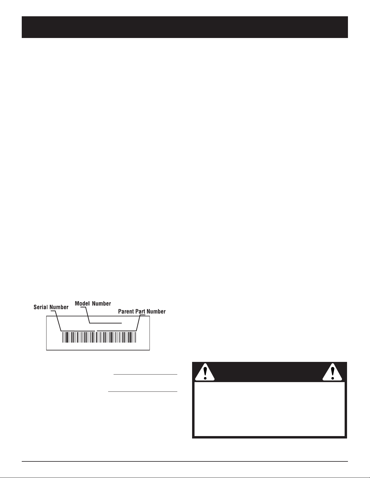
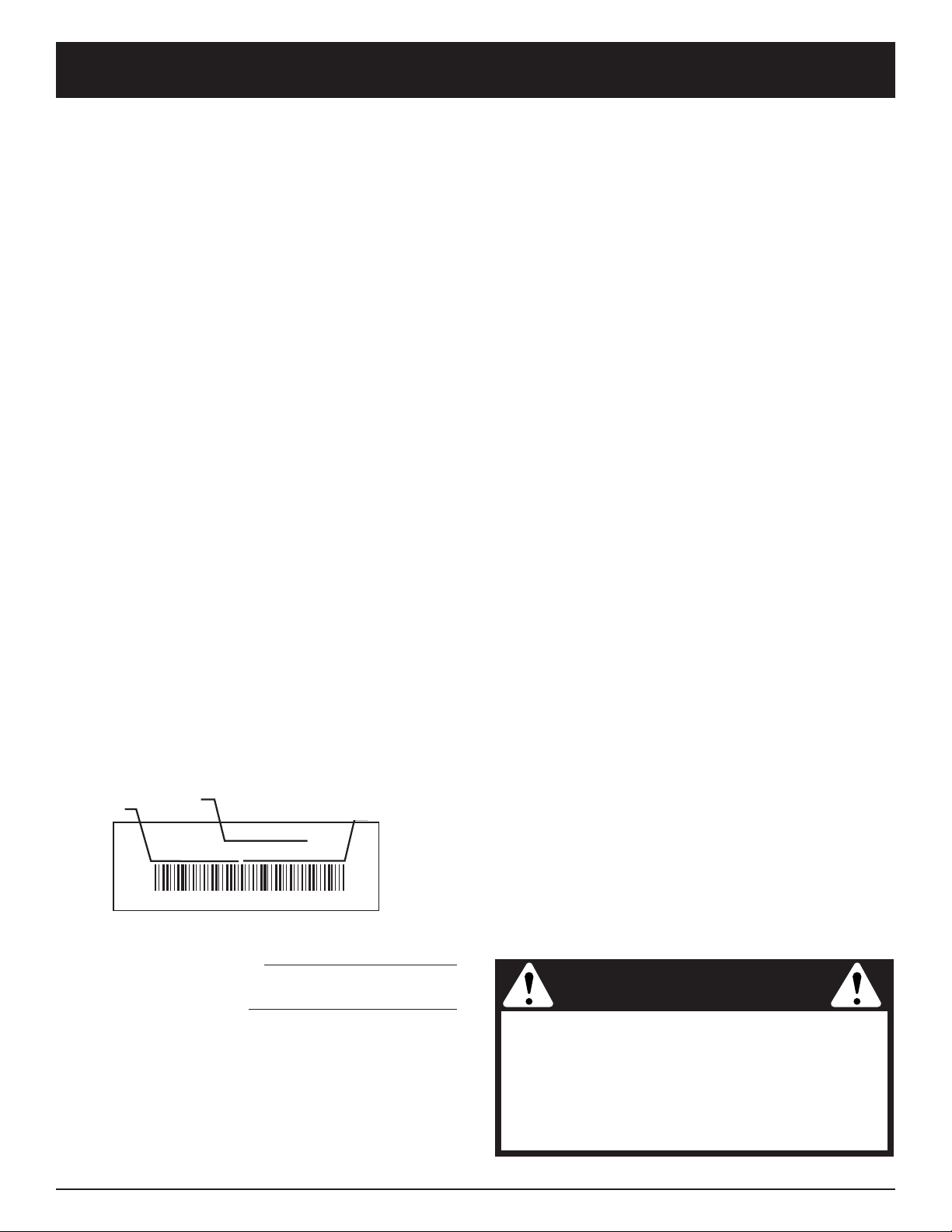
Before beginning, locate the unit’s model plate. It lists
the model and serial numbers of your unit. Refer to the
sample plate below and copy the information for future
reference.
Make sure you carefully read and understand this manual
before starting or operating this equipment.
THIS PRODUCT IS COVERED BY ONE OR MORE U.S.
PATENTS. OTHER PATENTS PENDING.
TABLE OF CONTENTS
Service Information . . . . . . . . . . . . . . . . . . . . . . . . .2
Rules for Safe Operation . . . . . . . . . . . . . . . . . . . . .3
Know Your Unit . . . . . . . . . . . . . . . . . . . . . . . . . . . .7
Assembly Instructions . . . . . . . . . . . . . . . . . . . . . . .8
Oil and Fuel Information . . . . . . . . . . . . . . . . . . . . .11
Starting/Stopping Instructions . . . . . . . . . . . . . . . .12
Operating Instructions . . . . . . . . . . . . . . . . . . . . . .13
Maintenance and Repair Instructions . . . . . . . . . . .15
Cleaning and Storage . . . . . . . . . . . . . . . . . . . . . . .18
Accessories and Replacement Parts . . . . . . . . . . .18
Troubleshooting Chart . . . . . . . . . . . . . . . . . . . . . .19
Specifications . . . . . . . . . . . . . . . . . . . . . . . . . . . . .20
Warranty Information . . . . . . . . . . . . . . . . . . . . . . .22
Parts List . . . . . . . . . . . . . . . . . . . .Inside Back Cover
Copy the model and parent
part number here:
SPARK ARRESTOR NOTE
NOTE: For users on U.S. Forest Land and in the
states of California, Maine, Oregon and Washington.
All U.S. Forest Land and the state of California (Public
Resources Codes 4442 and 4443), Oregon and
Washington require, by law that certain internal
combustion engines operated on forest brush and/or
grass-covered areas be equipped with a spark arrestor,
maintained in effective working order, or the engine be
constructed, equipped and maintained for the prevention
of fire. Check with your state or local authorities for
regulations pertaining to these requirements. Failure to
follow these requirements could subject you to liability or
a fine. This unit is factory equipped with a spark
arrestor. If it requires replacement, ask your LOCAL
SERVICE DEALER to install the Accessory Part
#753-04689 Spark Arrestor Kit.
CALIFORNIA PROPOSITION 65 WARNING
WARNING
THE ENGINE EXHAUST FROM THIS
PRODUCT CONTAINS CHEMICALS
KNOWN TO THE STATE OF CALIFORNIA
TO CAUSE CANCER, BIRTH DEFECTS
OR OTHER REPRODUCTIVE HARM.
MODEL :
S/N :
ITEM :

3
READ ALL INSTRUCTIONS
BEFORE OPERATING
• Read the instructions carefully. Be familiar with the
controls and proper use of the unit.
• Do not operate this unit when tired, ill, or under the
influence of alcohol, drugs, or medication.
• Children and teens under the age of 15 must not use
the unit, except for teens guided by an adult.
• All guards and safety attachments must be installed
properly before operating the unit.
• Inspect the unit before use. Replace damaged parts.
Check for fuel leaks. Make sure all fasteners are in
place and secure. Replace parts that are cracked,
chipped, or damaged in any way. Do not operate the
unit with loose or damaged parts.
• Clear the area of children, bystanders, and pets. At a
minimum, keep all children, bystanders, and pets
outside a 50 feet (15 m.) radius; there still may be a
risk to bystanders from thrown objects. Bystanders
should be encouraged to wear eye protection. If you
are approached, stop the unit immediately.
• Carefully inspect the area before starting the unit.
Remove all debris and hard or sharp objects such as
glass, wire, etc.
SAFETY WARNINGS FOR GAS UNITS
• Store fuel only in containers specifically designed and
approved for the storage of such materials.
• Avoid creating a source of ignition for spilled fuel. Do
not start the engine until fuel vapors dissipate.
• Always stop the engine and allow it to cool before filling
the fuel tank. Never remove the cap of the fuel tank, or
add fuel, when the engine is hot. Never operate the unit
without the fuel cap securely in place. Loosen the fuel
tank cap slowly to relieve any pressure in the tank.
• Mix and add fuel in a clean, well-ventilated outdoor area
where there are no sparks or flames. Slowly remove the
fuel cap only after stopping engine. Do not smoke while
fueling or mixing fuel. Wipe up any spilled fuel from the
unit immediately. Always wipe unit dry before using.
• Move the unit at least 30 feet (9.1 m) from the fueling
source and site before starting the engine. Do not
smoke or allow sparks and open flames near the area
while adding fuel or operating the unit.
RULES FOR SAFE OPERATION
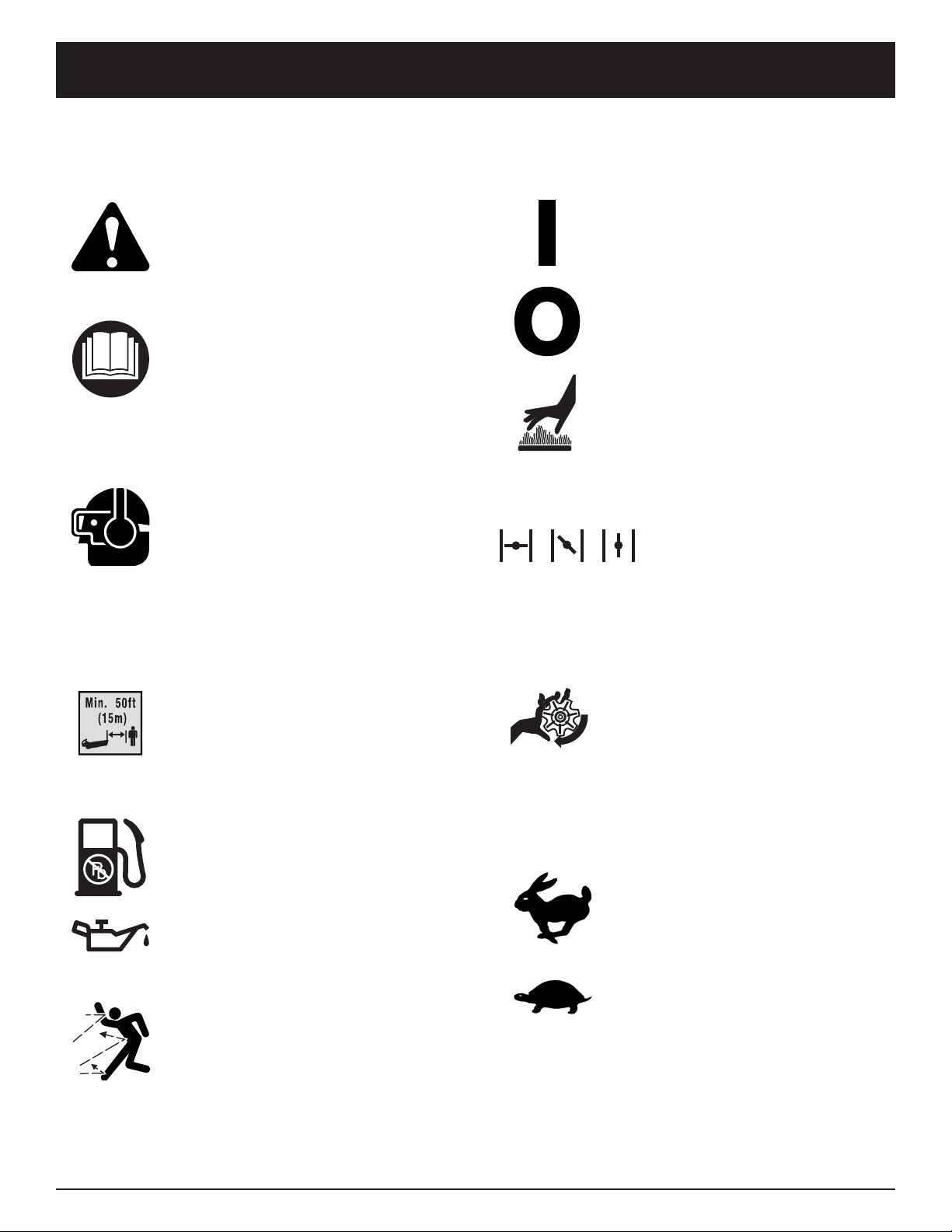
SYMBOL MEANING
The purpose of safety symbols is to attract your
attention to possible dangers. The safety symbols,
and their explanations, deserve your careful attention
and understanding. The safety warnings do not by
themselves eliminate any danger. The instructions or
warnings they give are not substitutes for proper
accident prevention measures.
NOTE: Advises you of information or instructions vital to
the operation or maintenance of the equipment.
SYMBOL MEANING
When using the unit,
you must follow the
safety rules. Please read these instructions
before operating the unit in order to ensure
the safety of the operator and any bystanders.
Please keep these instructions for later use.
WARNING:
• IMPORTANT SAFETY INSTRUCTIONS •
Failure to obey a
safety warning can
result in injury to yourself and others.
Always follow the safety precautions to
reduce the risk of fire, electric shock and
personal injury.
WARNING:
Failure to obey a
safety warning will
result in serious injury to yourself or to
others. Always follow the safety precautions
to reduce the risk of fire, electric shock and
personal injury.
DANGER:
Failure to obey a
safety warning may
result in property damage or personal injury
to yourself or to others. Always follow the
safety precautions to reduce the risk of fire,
electric shock and personal injury.
CAUTION:
Indicates
danger,
warning or caution. Attention is required in
order to avoid serious personal injury. May
be used in conjunction with other symbols
or pictographs.
SAFETY ALERT:
Gasoline is highly
flammable, and its
vapors can explode if ignited. Take the
following precautions:
WARNING:
Read the Operator’s Manual(s) and follow all
warnings and safety instructions.
Failure to do so can result in serious injury to the
operator and/or bystanders.
FOR QUESTIONS, CALL 1-800-345-8746 in the
United States, or 1-800-668-1238 in Canada

4
RULES FOR SAFE OPERATION
WHILE OPERATING
• Never start or run the unit inside a closed room or
building. Breathing exhaust fumes can kill. Operate this
unit only in a well-ventilated outdoor area.
• To reduce the risk of injury associated with thrown
objects, wear safety glasses or goggles that are
marked as meeting ANSI Z87. standards.
• Never run the unit without the the proper equipment
attached. When using this unit, always install the
blower/vacuum tubes and vacuum bag depending on
model. Make sure the vacuum bag is completely
zipped closed.
• To reduce the risk of hearing loss associated with
sound level(s), always wear ear/hearing protection
when operating this unit.
• Wear heavy, long pants, boots, and gloves. Do not
wear short pants, sandals, or go barefoot.
• To avoid static electricity shock, do not wear rubber
gloves or any other insulated gloves while operating
this unit.
• To reduce the risk of injury associated with objects
being drawn into rotating parts, do not wear loose
clothing, jewelry, scarves, and the like. Secure hair
above shoulder level.
•Wear a face or dust mask if the operation is dusty.
Long sleeve shirts are recommended.
• Use the unit only in daylight or good artificial light.
• Keep outside surfaces free from oil and fuel.
• Avoid accidental starting. Be in the starting position
whenever pulling the starter rope. The operator and
unit must be in a stable position while starting. Refer to
Starting/Stopping Instructions.
• Do not set unit on any surface except a clean, hard
area while engine is running. Debris such as gravel,
sand, dust, grass, etc. could be picked up by the air
intake and thrown out by the discharge opening,
damaging unit, property, or causing serious injury to
bystanders or operator.
• Use the right tool. Only use this tool for the purpose
intended.
• Do not force unit. It will do the job better and with less
likelihood of injury at a rate for which it was designed.
• Do not overreach or use from unstable surfaces such
as ladders, trees, steep slopes, rooftops, etc. Always
keep proper footing and balance.
• Always hold the unit with a firm grip when operating.
• Keep hands, face, and feet at a distance from all moving
parts. Do not touch or try to stop the impeller when it is
rotating. Do not operate without guards in place.
• Do not put any object into openings. Do not use with
any opening blocked; keep free of dirt, debris, and
anything that may reduce the air flow.
• Do not touch the engine or muffler. These parts get
extremely hot from operation. When turned off they
remain hot for a short time.
• Do not operate the engine faster than the speed
needed to do the job. Do not run the engine at high
speed when not in use.
• Always stop the engine when operation is delayed or
when walking from one location to another.
• Stop the engine for maintenance, repair, to install or
remove the blower tubes or vacuum attachments. The
unit must be stopped and the impeller no longer
turning to avoid contact with the rotating blades.
• Use only original equipment manufacturer replacement
parts when servicing this unit. These parts are available
from your authorized service dealer. Do not use
unauthorized parts, accessories, or attachments for
this unit. Doing so could lead to serious injury to the
user, or damage to the unit, and void your warranty.
• Never use this unit for spreading chemicals, fertilizers or
other substances which may contain toxic materials.
•To reduce fire hazard, replace faulty muffler and spark
arrestor, keep the engine and muffler free from grass,
leaves, excessive grease or carbon build up.
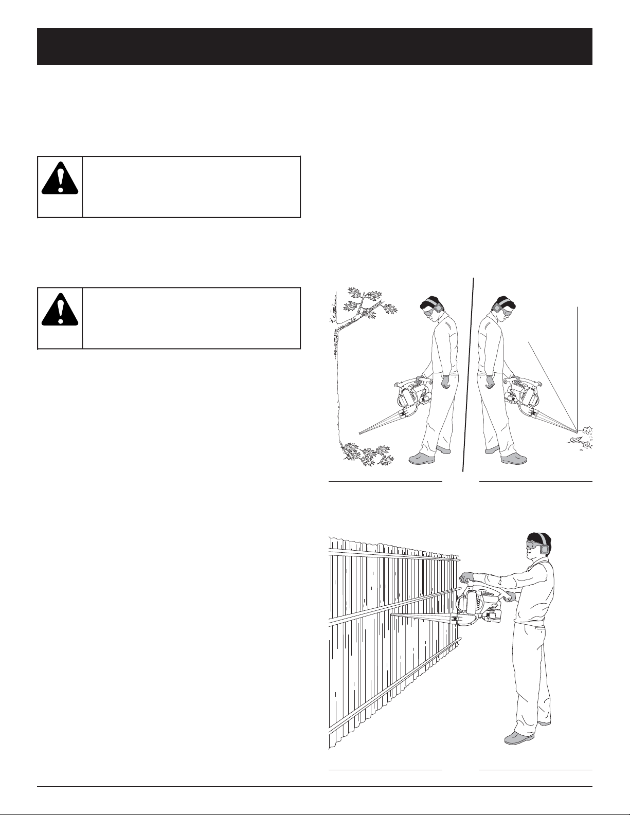
WHILE OPERATING UNIT AS A BLOWER
• Never point the blower in the direction of people or
pets, or in the direction of windows. Always direct the
blowing debris away from people, animals, and
windows. Use extra caution when blowing debris near
solid objects such as trees, automobiles, walls, etc.
WHILE OPERATING UNIT AS A VACUUM
• Avoid situations that could catch the vacuum bag on
fire. Do not operate near an open flame. Do not
vacuum warm ash from fireplaces, barbecue pits,
brush piles, etc. Do not vacuum discarded cigars or
cigarettes unless the cinders are completely cool.

5
• The unit is designed to pickup dry material such as
leaves, grass, small twigs, and bits of paper. Do not
attempt to vacuum wet debris and/or standing water
as this may result in damage to the blower/ vacuum.
To avoid severe damage to the impeller, do not
vacuum metal, broken glass, etc.
OTHER SAFETY WARNINGS
• Always disconnect the spark plug before performing
maintenance or accessing movable parts.
• Never store the unit, with fuel in the tank, inside a
building where fumes may reach an open flame (pilot
lights, etc.) or sparks (switches, electrical motors, etc.).
• Allow the engine to cool before storing or transporting.
Be sure to secure the unit while transporting.
• Store the unit in a dry place, either locked up or up
high to prevent unauthorized use or damage. Keep out
of the reach of children.
• Never douse or squirt the unit with water or any other
liquid. Keep handles dry, clean, and free from debris.
Clean after each use, see Cleaning and Storage
instructions.
• Keep these instructions. Refer to them often and use
them to instruct other users. If you loan this unit to
others, also loan these instructions to them.
SPECIAL NOTE: Exposure to vibrations through
prolonged use of gasoline powered hand tools could
cause blood vessel or nerve damage in the fingers,
hands, and joints of people prone to circulation disorders
or abnormal swelling. Prolonged use in cold weather has
been linked to blood vessel damage in otherwise healthy
people. If symptoms occur such as numbness, pain, loss
of strength, change in skin color or texture, or loss of
feeling in the fingers, hands or joints, discontinue use of
this tool and seek medical attention. An anti-vibration
system does not guarantee avoidance of these
problems. Users who operate power tools on a regular
basis must closely monitor their physical condition and
the condition of this tool.
SA VE THESE INSTRUCTIONS
RULES FOR SAFE OPERATION
6
RULES FOR SAFE OPERATION
SYMBOL MEANING
• SAFETY ALERT SYMBOL
Indicates danger, warning, or
caution. May be used in conjunction
with other symbols or pictographs.
• WARNING - READ OPERATOR'S
MANUAL
Read the Operator’s Manual(s) and
follow all warnings and safety
instructions. Failure to do so can
result in serious injury to the
operator and/or bystanders.
• WEAR EYE AND HEARING
PROTECTION
WARNING: Thrown objects and
loud noise can cause severe eye
injury and hearing loss. Wear eye
protection meeting ANSI Z87.1-1989
standards and ear protection when
operating this unit.
Use a full face
shield when needed.
• KEEP BYSTANDERS AWAY
WARNING: Keep all bystanders,
especially children and pets, at least
50 feet (15 m.) from the operating area.
• UNLEADED FUEL
Always use clean, fresh unleaded fuel.
• OIL
Refer to operator's manual for the
proper type of oil.
• THROWN OBJECTS AND
ROTATING CUTTER CAN CAUSE
SEVERE INJURY
WARNING: Keep clear of blower
outlet. Never point the blower at
yourself or others. Objects can be
thrown from blower. Do not
operate unit without proper
attachments and guards in place.
SAFETY AND INTERNATIONAL SYMBOLS
This operator's manual describes safety and international symbols and pictographs that may appear on this product.
Read the operator's manual for complete safety, assembly, operating and maintenance and repair information.
SYMBOL MEANING
•ON/OFF STOP CONTROL
ON / START / RUN
•ON/OFF STOP CONTROL
OFF OR STOP
• HOT SURFACE WARNING
Do not touch a hot muffler or
cylinder. You may get burned. These
parts get extremely hot from
operation. When turned off they
remain hot for a short time.
•
CHOKE CONTROL
1 • FULL choke position.
2 •
PARTIAL choke position.
3 •
RUN position.
• BLOWERS – ROTATING
IMPELLER BLADES CAN
CAUSE SEVERE INJURY
WARNING: Stop the engine and
allow the impeller to stop before
opening the vacuum door, installing
or changing tubes or bag, or before
cleaning or performing any
maintenance
.
• THROTTLE CONTROL
Indicates “HIGH” or “FASTEST” speed.
• THROTTLE CONTROL
Indicates “IDLE”, “LOW” or
“SLOWEST” speed.
12
3
7
RULES FOR SAFE OPERATION
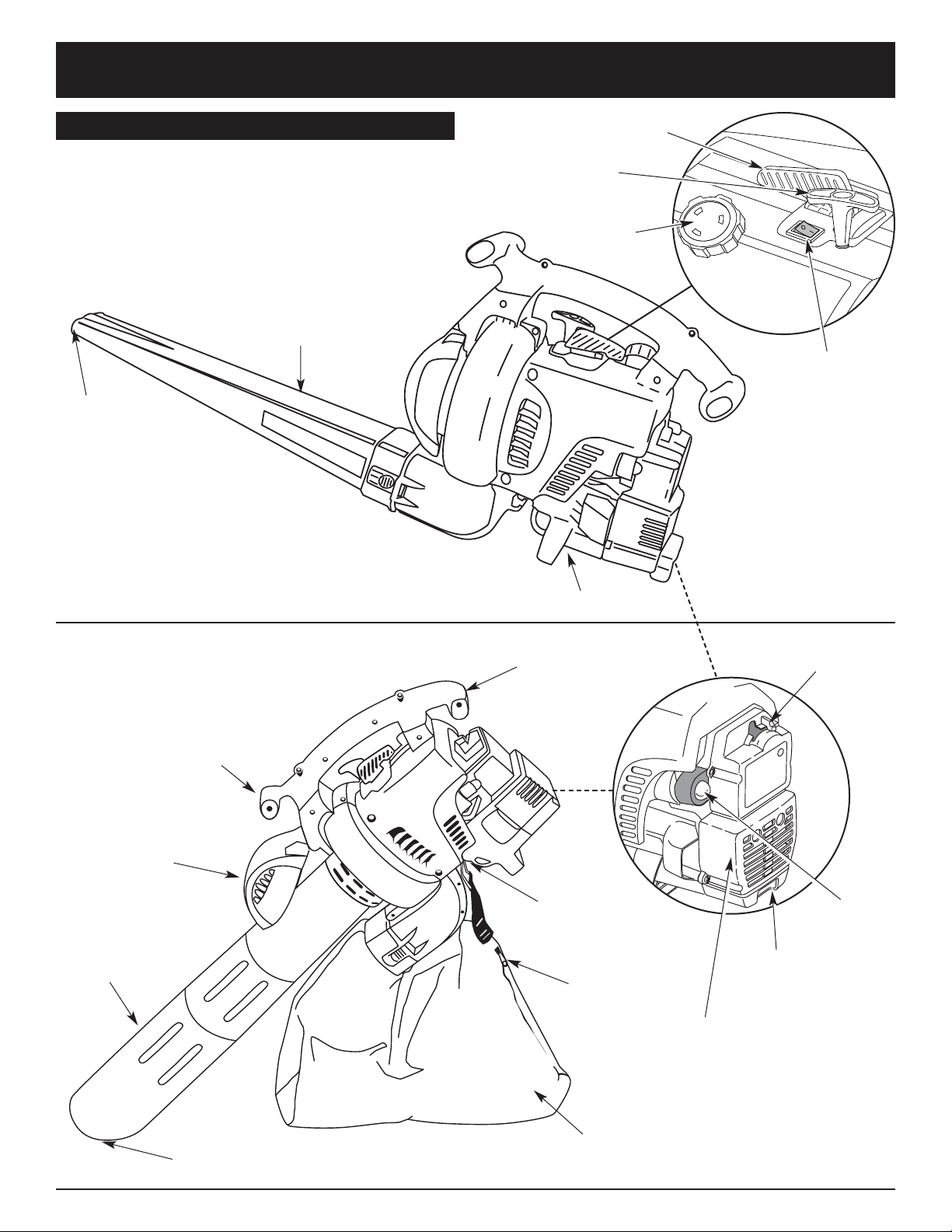
APPLICATION
As a blower:
• Cleaning yards, garages, driveways, porches,
patios, around walls, fences and more
As a vacuum:
• Picking up leaves and other light debris
Blower Tube
Vacuum Bag
Blower
Outlet
Vacuum
Bag Hook
Vacuum Bag
Zipper
Fuel Cap
Throttle Control
Primer
Bulb
Blue Choke
Control
Air filter/muffler cover
Spark Plug
Starter Rope
Grip
On/Off Stop
Control
KNOW YOUR UNIT
Muffler
Assembled as a Blower
Assembled as a Vacuum
Vacuum
Door
Front Handle
Vacuum Inlet
Vacuum
Tube
Rear Handle
8
ASSEMBLY INSTRUCTIONS
ASSEMBLING UNIT AS A BLOWER
Blower Tube Assembly
NOTE: If the unit was assembled as a vacuum unit,
remove all vacuum parts and store away in a
secure place for later use.
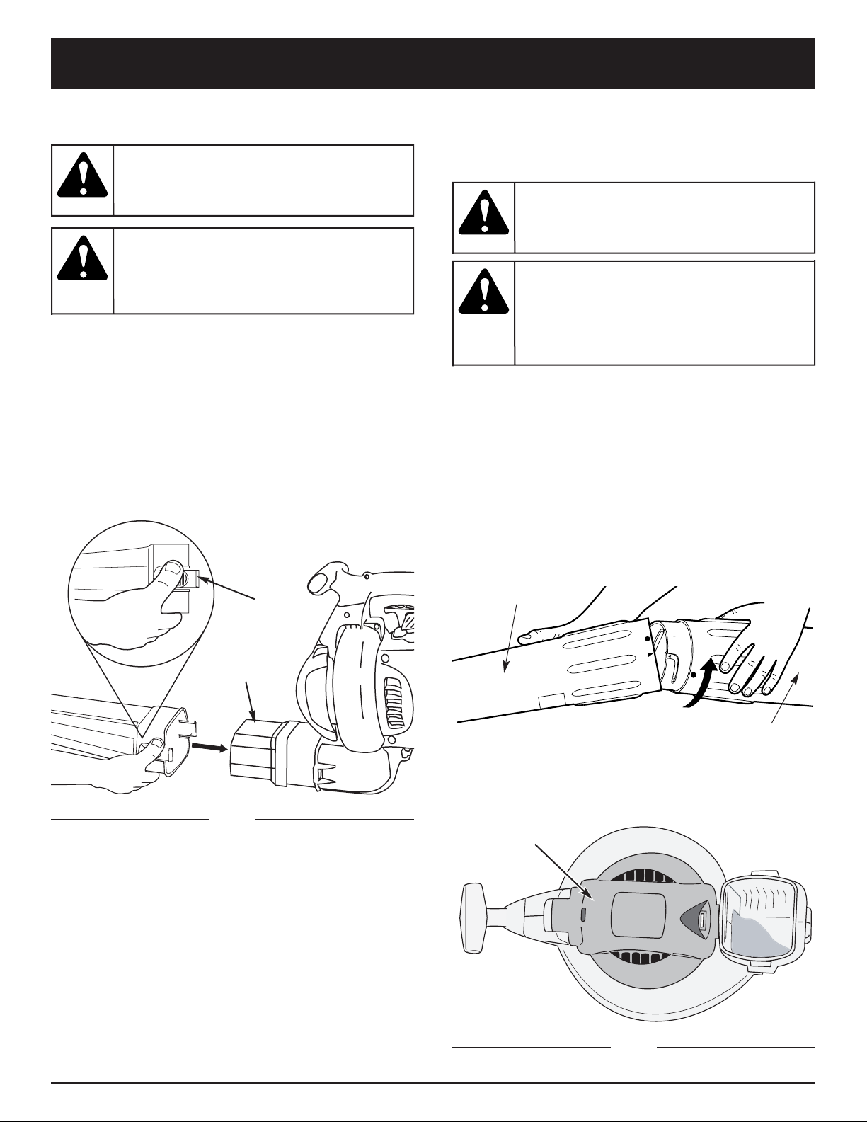
Installing
• Install the blower tube over the blower outlet and push
it on until both tabs snap into place (Fig. 1).
Removing
• Remove the blower tube by pressing both tabs at the
same time and pulling off the blower tube (Fig. 1).
ASSEMBLING UNIT AS A VACUUM
To assemble the unit as a vacuum, begin by removing
the blower tube. Refer to the previous section.
Vacuum Tube Assembly
NOTE: If the unit was assembled as a blower unit,
remove the blower tube and store away in a
secure place for later use.
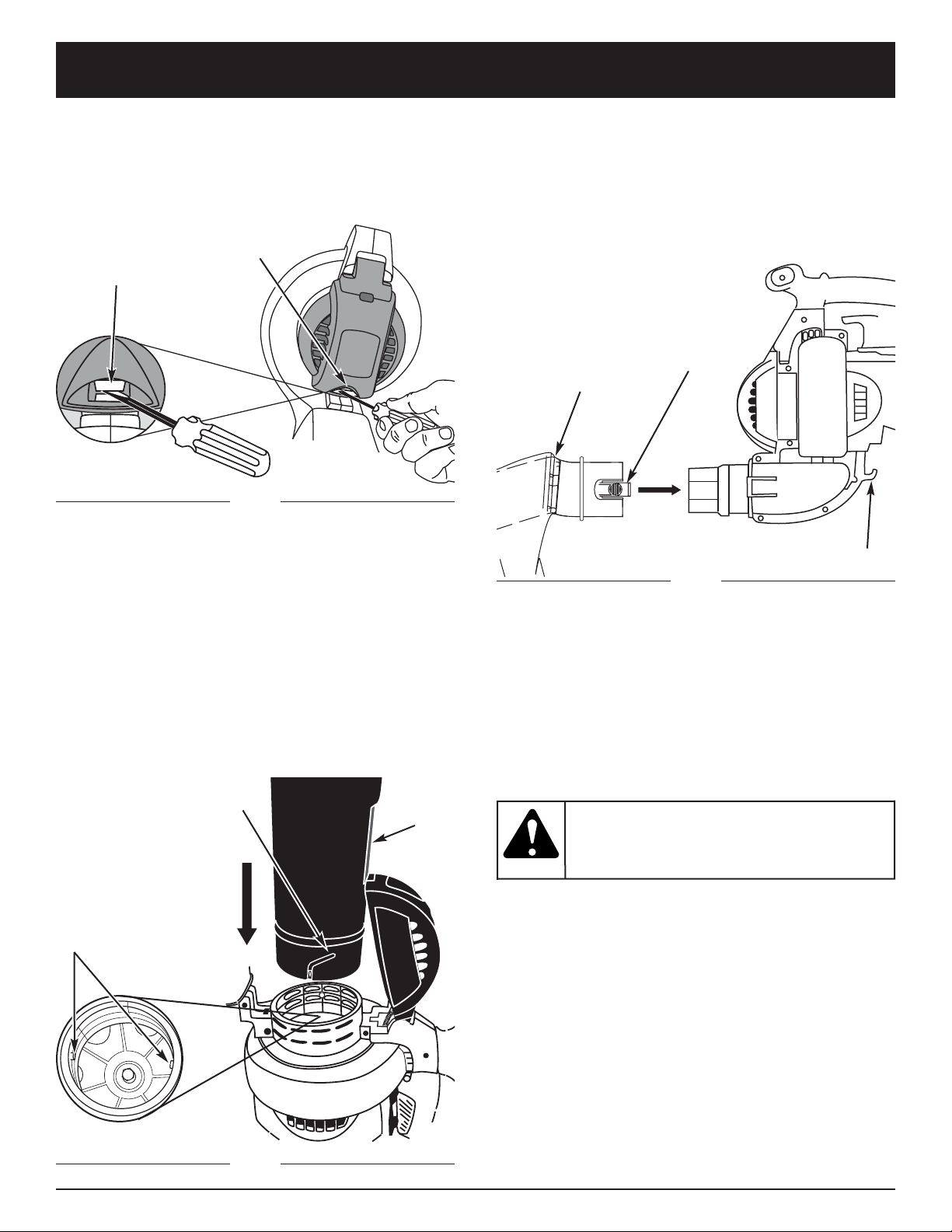
Installation
1. Align the small arrow on the lower vacuum tube with
the arrow on the upper vacuum tube (Fig. 2).
2. Grasp the lower and upper vacuum tubes firmly with
both hands, and push the lower vacuum tube into
the upper vacuum tube. Turn the lower vacuum tube
clockwise until it snaps into detente and locks. When
properly assembled, the dot on the lower tube aligns
with the dot on the upper tube.
3. Flip the unit so it is standing straight up on the
muffler cover. The front of the unit and the vacuum
door should face you (Fig. 3).
Fig. 1
Fig. 2
Fig. 3
Tabs
Vacuum
Door
Blower
Outlet
Upper Vac Tube
Lower Vac Tube
To pr event serious
personal injury , stop
the engine and allow the impeller to stop
before attaching or removing tubes.
WARNING:
To prevent serious
personal injury or
damage to the unit, the blower tube must
be installed while operating this unit as a
blower.
WARNING:
To pr event serious
personal injury , stop
the engine and allow the impeller to stop
before attaching or removing tubes.
WARNING:
To pr event serious
personal injury or
damage to the unit, always install vacuum
tubes and the vacuum bag, and make sure
the vacuum bag is completely zipped closed
when operating this unit as a vacuum.
WARNING:
9
ASSEMBLY INSTRUCTIONS
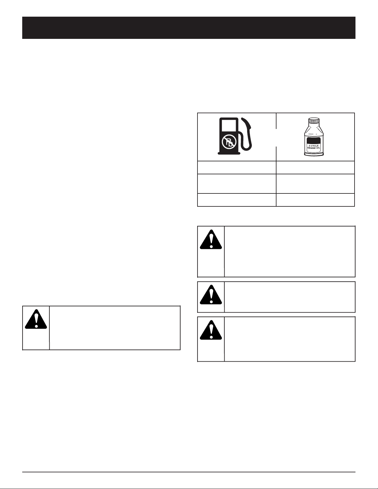
4. Insert a flat head screwdriver into the slot at the
lower end of the vacuum door. Make contact with
the vacuum door locking clip and push inward and
upwards (Fig. 4). Then pull the vacuum door and
hold it open.
5. While holding the vacuum door open, locate the
assembled vacuum tube (put together in Step 2).
Arrange the tube so the flat area faces the vacuum
door. The grooves on the side of the tube will line up
with the small tabs in the impeller intake (Fig. 5).
From the exterior, align the small arrow on the
vacuum tube with the arrow on the impeller intake.
6. Push the vacuum tube in firmly and grip it with both
hands. Turn the tube clockwise as far as possible
until it snaps into the detente and locks. When
properly assembled, the dot on the vacuum tube will
align with the dot on the impeller intake.
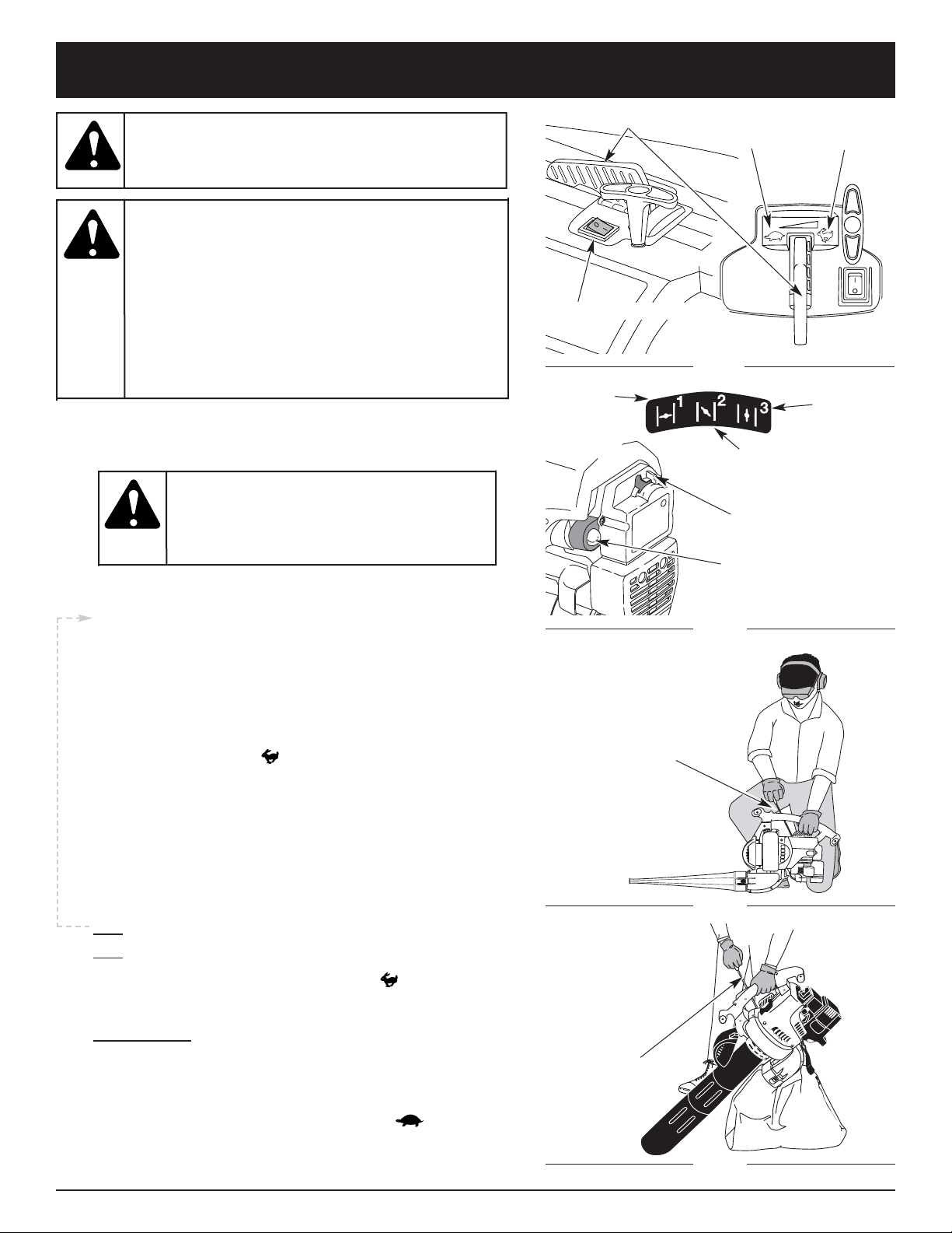
Removing the Vacuum Bag
1. Unhook the bag.
2. Remove the vacuum bag by pressing both tabs on
the vacuum bag elbow at the same time and pulling
the bag off the blower (Fig. 6).
3. Install the blower tube in order to assemble the unit
as a blower.
4. Make sure the vacuum door is securely latched shut.
Elbow
Tabs
Locking
Clip
Fig. 4
Installing the Vacuum Bag
7. Install the vacuum bag tube over the blower outlet
and push it on until both tabs snap into place (Fig. 6).
Position the bag so its interior elbow slants
downward.
8. Attach the vacuum bag to the vacuum bag hook
located at the underside of the unit.
Fig. 6
Vacuum
Door Slot
Flat
Area
Tabs
Impeller Intake
Vacuum Tube
Groove
Fig. 5
Vacuum Bag Hook
Never operate the
unit in the blower
configuration without the vacuum door
secured and latched shut.
WARNING:

10
Fig. 9
3. Snap the clip on to the support fittings on the front
or back of the handle. Clip to the front portion of the
handle when using the unit as a blower, and clip to
the back portion of the handle when using the unit as
a vacuum (Fig. 8).
4. While standing in the operating position, adjust the
length to fit the operator’s size. Pull the tab to
lengthen, pull the strap to shorten (Fig 9).
INST ALLING THE SHOULDER HARNESS
1. Push the strap through the center of the buckle.
2. Pull the strap over the cross bar and down through
the slot in the buckle (Fig. 7).
Fig. 7
Clip
ASSEMBLY INSTRUCTIONS
To avoid serious
personal injury,
never attempt to start the unit when
standing with the unit clipped to the
shoulder strap. Always follow the starting
procedures as described in the Starting/
Stopping Instructions section.
WARNING:
Attach Here for
Blowing
Attach Here for
Vacuuming
Fig. 8
11
OIL AND FUEL INFORMATION
NOTE: Dispose of the old fuel/oil mix in accordance to
Federal, State and Local regulations.
OIL AND FUEL MIXING INSTRUCTIONS
Old and/or improperly mixed fuel are the main reasons
for the unit not running properly. Be sure to use fresh,
clean unleaded fuel. Follow the instructions carefully for
the proper fuel/oil mixture.
Definition of Blended Fuels
Today's fuels are often a blend of gasoline and
oxygenates such as ethanol, methanol, or MTBE (ether).
Alcohol-blended fuel absorbs water. As little as 1%
water in the fuel can make fuel and oil separate. It forms
acids when stored. When using alcohol-blended fuel,
use fresh fuel (less than 60 days old).
Using Blended Fuels
If you choose to use a blended fuel, or its use is
unavoidable, follow recommended precautions:
• Always use the fresh fuel mix explained in your
operator's manual
• Always agitate the fuel mix before fueling the unit
• Drain the tank and run the engine dry before storing
the unit
Using Fuel Additives
The bottle of 2-cycle oil that came with your unit
contains a fuel additive which will help inhibit corrosion
and minimize the formation of gum deposits. It is
recommended that you use our 2-cycle oil with this unit.
If unavailable, use a good 2-cycle oil designed for
air-cooled engines along with a fuel additive, such as
STA-BIL®Gas Stabilizer or an equivalent. Add 0.8 oz.
(23 ml.) of fuel additive per gallon of fuel according to the
instructions on the container. NEVER add fuel additives
directly to the unit's fuel tank.
Thoroughly mix the proper ratio of 2-cycle engine oil
with unleaded gasoline in a separate fuel can. Use a 40:1
fuel/oil ratio. Do not mix them directly in the engine fuel
tank. See the table below for specific gas and oil mixing
ratios.
NOTE: One gallon (3.8 liters) of unleaded gasoline mixed
with one 3.2 oz. (95 ml.) bottle of
2-cycle oil makes a 40:1 fuel/oil ratio.
UNLEADED GAS 2 CYCLE OIL
1 GALLON US
(3.8 LITERS)
3.2 FL. OZ.
(95 ml)
1 LITER 25 ml
+
MIXING RATIO - 40:1
Add fuel in a clean,
well ventilated
outdoor area. Wipe up any spilled fuel
immediately. Avoid creating a source of
ignition for spilt fuel. Do not start the engine
until fuel vapors dissipate.
WARNING:
Gasoline is
extremely
flammable. Ignited Vapors may explode.
Always stop the engine and allow it to cool
before filling the fuel tank. Do not smoke
while filling the tank. Keep sparks and open
flames at a distance from the area.
WARNING:
Remove fuel cap
slowly to avoid injury
from fuel spray. Never operate the unit
without the fuel cap securely in place
.
WARNING:
For proper engine
operation and
maximum reliability, pay strict attention to
the oil and fuel mixing instructions on the
2-cycle oil container. Using improperly mixed
fuel can severely damage the engine.
CAUTION:
12
STARTING/STOPPING INSTRUCTIONS
Blue Choke Lever
On/Off Stop Control
Primer Bulb
Throttle Control
Idle
Fast
STARTING INSTRUCTIONS
Fig. 10
Fig. 11
STOPPING INSTRUCTIONS
1. Move the throttle control to the idle position ( ). Allow the
engine to cool down by idling.
2. Put the On/Off Stop Control in the OFF (O) position.
1. Mix gas with oil. Fill fuel tank with fuel/oil mixture. See
Oil and Fuel Mixing Instructions.
NOTE: There is no need to turn the unit on. The On/Off
Stop Control is in the ON (I) position at all times.
2. Fully press and release the primer bulb 10 times,
slowly. Some amount of fuel should be visible in the
primer bulb and fuel lines (Fig. 11). If you can’t see
fuel in the bulb, press and release the bulb as many
times as it takes before you can see fuel in it.
3. Place the blue choke lever in Position 1 (Fig. 11).
4. Place the unit in the starting position (Fig. 12 as a
blower, Fig. 13 as a vacuum). Move the throttle control
to the fast position ( ) (Fig. 10).
5. Pull the starter rope briskly 5 times.
6. Place the blue choke lever in Position 2.
7. Pull the starter rope briskly 1 to 3 times to start the
engine.
8. Allow the engine to warm up for 15 to 30 seconds.
9. Place the blue choke lever in Position 3. The unit is
ready for use.
IF... The engine does not start, go back to step 2.
IF... The engine fails to start after a couple attempts, place
the blue choke lever in Position 3 and move the
throttle control to the fast position ( ). Pull the
starter rope briskly 3 to 8 times. The engine should
start. If not, repeat.
IF WARM... If the engine is already warm, start the unit
with the blue choke lever in Position 2. After the unit
starts, move the choke lever to Position 3.
Position 1
Position 3
Vacuum
Starting
Position
Position 2
Starter
Rope
Starter
Rope
Blower
Starting
Position
Fig. 12
Fig. 13
Operate this unit only in a
well- ventilated outdoor
area. Carbon monoxide exhaust fumes can be
lethal in a confined area.
WARNING:
Avoid accidental starting.
Make sure you are in the
starting position when pulling the starter rope (Fig.
12 and 13).
To avoid serious injury, the operator and
unit must be in a stable position while starting.
Do not set unit on any surface except a clean, hard
area while starting. Debris such as gravel, sand,
dust and grass could be picked up by the air
intake and thrown out by the discharge opening.
This could damage the unit, property, or cause
serious injury to bystanders or the operator.
WARNING:
To avoid serious
personal injury,
always remove the vacuum bag prior to
refueling the unit. The bag may become a
fire hazard when saturated with fuel.
WARNING:
13
OPERATING INSTRUCTIONS
HOLDING THE BLOWER/VACUUM
Before operating the unit, stand in the operating position.
Check for the following:
• Operator is wearing proper clothing, such as boots,
safety glasses or goggles, ear/hearing protection,
gloves, long pants and long sleeve shirt
• If the conditions are dusty, the operator is wearing a
dust mask or face mask
• The unit is in good working condition
• The tubes and guards are in place and secure
OPERATING TIPS
• Be sure the vacuum bag is zipped closed before
operating the unit.
• Assure the unit is not directed at anybody or any loose
debris before starting the unit.
• Verify that the unit is in good working condition. Make
sure the tubes and guards are in place and secure.
• Always hold the unit securely when operating. Keep a
firm grip on the handles.
• To reduce the risk of hearing loss associated with sound
level(s), hearing protection is required.
• Operate power equipment only at reasonable hours—
not early in the morning or late at night when people
might be disturbed. Comply with times listed in local
ordinances. Usual recommendations are 9:00 am to
5:00 pm, Monday through Saturday.
• To reduce noise levels, limit the number of pieces of
equipment used at any one time.
• To reduce noise levels, operate power blowers at the
lowest possible speed to do the job.
• Check your equipment before operation, especially the
muffler, air intakes and air filters.
• Use rakes and brooms to loosen debris before blowing.
• In dusty conditions, slightly dampen surfaces or use a
mister attachment when water is available.
• Conserve water by using power blowers instead of
hoses for many lawn and garden applications,
including areas such as screens, patios, grills, porches,
and gardens.
•Watch out for children, pets, open windows or freshly
washed cars, and blow debris safely away.
• Use the full blower nozzle extension so the air stream
can work close to the ground.
• Clean up after using blowers and other equipment.
Dispose of debris appropriately.
OPERATING AS A BLOWER
1 Use the blower for trees, shrubs, flower beds and
hard-to-clean areas (Fig. 14).
2. Use the unit around buildings and for other normal
cleaning procedures (Fig. 14).
3. Use the blower around walls, overhangs, fences and
screens (Fig. 15).
Fig. 14
Fig. 15
To pr event serious
personal injury or
damage to the unit, make sure blower tubes
or vacuum tubes and the vacuum bag are in
place before you operate the unit.
WARNING:
To avoid serious
personal injury,
wear goggles or safety glasses at all times
when operating this unit. Wear a face mask
or dust mask in dusty locations.
WARNING:
14
OPERATING INSTRUCTIONS
Fig. 16
OPERATING AS A VACUUM
Check for the following before operating the unit:
• Operator is wearing proper clothing, such as boots,
safety glasses or goggles, ear/hearing protection,
gloves, long pants and long sleeve shirt
• If the conditions are dusty, operator is equipped with a
dust mask or face mask
• The unit is in good working condition-- the vacuum
tubes and vacuum bag are in place and secure.
• The vacuum bag harness is in place and correctly
adjusted
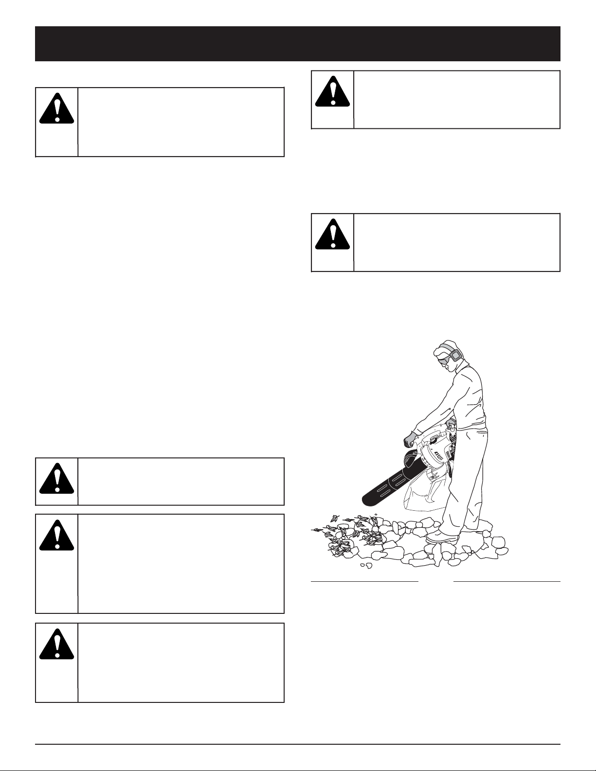
Operation Procedure
Use the unit for vacuuming up light debris like leaves
and paper.
Hold the vacuum, tilting the suction tube slightly (2-4
inches or 50-100 mm), and use a sweeping action to
collect light debris (Fig. 16). The debris will flow into the
vacuum bag. Items such as small leaves and small twigs
will be mulched as they pass through the fan housing,
allowing the vacuum bag to hold more debris.
When the bag is full, suction will noticeably decrease.
Turn off the unit and allow the impeller to stop before
you remove and unzip the bag. Unzip the bag and empty
the contents before continuing. Refer to Emptying the
Vacuum Bag.
Emptying the Vacuum Bag
1. Remove the bag from the vacuum bag hook.
2. While wearing eye protection and a dust mask, unzip
the vacuum bag and empty the contents into a
garbage bag or container.
3. Turn the bag inside out after initial emptying and
vigorously shake out dust and debris.
4. Zip close and reinstall the vacuum bag.
To avoid serious
personal injury, turn
off the unit and allow the impeller to stop
before opening vacuum door or installing or
removing vacuum bag.
WARNING:
When the upper and
lower vacuum tubes
are removed, make sure the vacuum door is
snapped closed and secured before using
the unit, to avoid injury from the impeller.
WARNING:
Avoid situations that
could catch the
vacuum bag on fire. Do not operate near an
open flame. Do not vacuum warm ash from
fireplaces, barbecue pits, brush piles, etc. Do
not vacuum discarded cigars or cigarettes
unless the cinders are completely cool.
WARNING:
As a vacuum, the
unit is designed to
pick up dry material such as leaves, grass,
small twigs and bits of paper. To avoid serious
personal injury, do not attempt to vacuum wet
debris and/or standing water as this may
result in damage to the blower/ vacuum. To
avoid severe damage to the impeller, do not
vacuum metal, broken glass or similar items.
WARNING:
To avoid serious
personal injury,
never unzip the vacuum bag without
stopping the unit first
WARNING:
To prevent serious
personal injury or
damage to the unit, always install vacuum
tubes, vacuum bag and make sure the
vacuum bag is completely zipped closed
when operating this unit as a vacuum.
WARNING:
15
MAINTENANCE AND REPAIR INSTRUCTIONS
MAINTENANCE SCHEDULE
Perform these required maintenance procedures at the
frequency stated in the table. These procedures should
also be a part of any seasonal tune-up.
NOTE: Some maintenance procedures may require
special tools or skills. If you are unsure about
these procedures take your unit to any non-road
engine repair establishment, individual or
authorized service dealer.
NOTE: Maintenance, replacement, or repair of the
emission control devices and system may be
performed by any non-road engine repair
establishment, individual or authorized service
dealer.
In order to assure peak performance of your engine,
inspection of the engine exhaust port may be necessary
after 50 hours of operation. If you notice lost RPM, poor
performance or general lack of acceleration, this service
may be required. If you feel your engine is in need of this
inspection, refer service to any non-road engine repair
establishment, individual or authorized service dealer for
repair. DO NOT attempt to perform this process yourself
as engine damage may result from contaminants
involved in the cleaning process for the port.
FREQUENCY MAINTENANCE REQUIRED REFER TO
Before starting engine Fill fuel tank with fresh fuel Page 11
Every 10 hours Clean and re-oil air filter Page 15
Every 25 hours
Check and clean spark arrestor
Check spark plug condition and gap
Page 16
Page 17
Every 50 hours
Inspect exhaust port and spark arrestor screen for clogging or
obstruction to assure maximum performance levels
Page 16
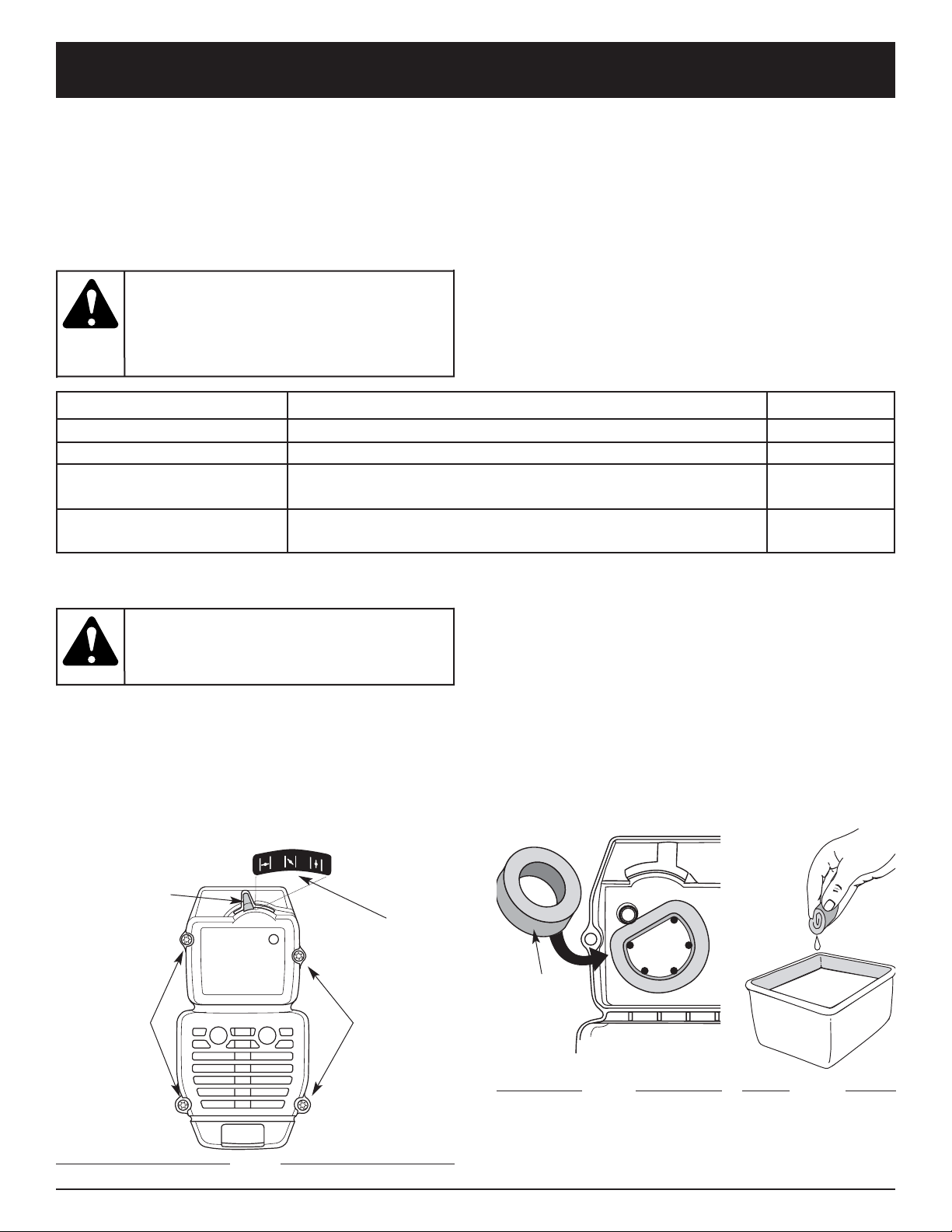
AIR FILTER MAINTENANCE
Removing the Air Filter/Muffler Cover
1. Place the choke lever in Position 2.
NOTE: The blue choke lever must be in Position 2 to
remove the air filter/ muffler cover.
2. Remove the four (4) screws securing the air
filter/muffler cover (Fig. 17). Use a T-20 Torx bit
screwdriver.
3. Pull the cover from the engine. Do not force.
Cleaning the Air Filter
Clean and re-oil the air filter every 10 hours of operation.
It is an important item to maintain. Failure to maintain
your air filter properly can result in poor performance or
can cause permanent damage to your engine.
1. Remove air filter/muffler cover. Refer to Removing
the Air Filter/Muffler Cover.
2. Turn cover over and look inside to locate the air filter.
Remove the air filter from inside the air filter/muffler
cover (Fig. 18).
3. Wash the filter in detergent and water (Fig. 19). Rinse
the filter thoroughly. Squeeze out excess water. Allow
it to dry completely.
Fig. 18
Fig. 19
Air Filter
Inside Muffler
Cover
To avoid serious
personal injury,
always turn your unit off and allow it to cool
before you clean or service it.
WARNING:
To prevent serious
injury, never perform
maintenance or repairs with unit running.
Always service and repair a cool unit.
Disconnect the spark plug wire to ensure that
the unit cannot start.
WARNING:
Blue Choke
Lever
Screws
Screws
Position 2
Fig. 17
16
MAINTENANCE AND REPAIR INSTRUCTIONS
Fig. 20
Fig. 21
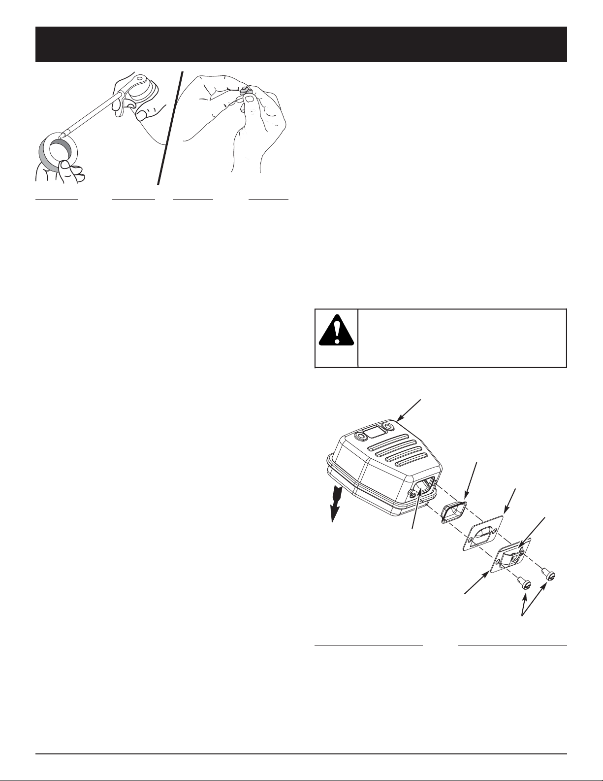
4. Apply enough clean SAE 30 oil to lightly coat the
filter (Fig. 20).
5. Squeeze the filter to spread and remove excess oil
(Fig. 21).
6. Replace the air filter inside the air filter/muffler cover
(Fig. 18).
NOTE: Operating the unit without the air filter and air
filter/muffler cover assembly will VOID the
warranty.
Reinstalling the Air Filter/Muffler Cover
1. Place the air filter/muffler cover over the back of the
carburetor and muffler. Align the screw holes.
2. Insert the four (4) screws into the holes in the air
filter/muffler cover (Fig. 17) and tighten.
Do not over tighten.
If the exhaust
deflector assembly is
not tightened securely, it could fall off causing
damage to the unit and possible serious
personal injury.
WARNING:
SPARK ARRESTOR MAINTENANCE
NOTE: The exhaust can only flow in one direction: AWAY
from the engine. Pay close attention when
disassembling the muffler so you can put it back
together correctly. Failure to do so will damage
the unit and may cause serious personal injury.
1. Remove air filter/muffler cover. Refer to Removing
the Air Filter/Muffler Cover.
2. Locate the muffler, but do not remove it. Find the two
(2) screws on the bottom of the muffler (Fig. 22).
These two screws hold the Spark Arrestor Hood
Assembly and the spark arrestor screen to the
bottom of the muffler. Remove the two (2) screws
using either a torx #20 or flat blade screwdriver.
3. Using a small flat blade screwdriver, carefully pry up
the spark arrestor screen from the recessed hole,
taking care to notice that the “raised” part of the
spark arrestor screen is inside the recessed hole.
Remove the spark arrestor screen from the muffler.
Spark Arrestor
Screen
Spark Arrestor
Plate
Spark Arrestor
Hood
Screws
Muffler
Recessed Hole
Engine
Spark Arrestor Hood
Assembly Includes:
Spark Arrestor Plate
Spark Arrestor Hood
and Screws
Opening
Fig. 22
4. Clean the spark arrestor screen with a wire brush.
Replace it if it is damaged, or if you are unable to
clean it thoroughly.
5. Reinstall the spark arrestor screen by putting the
“raised” portion of the screen inside the recessed
hole of the muffler. Make sure that the spark arrestor
screen fits flat against the muffler.
6. Place the spark arrestor plate on top of the spark
arrestor with the “raised” side up and the opening
facing towards the engine (Fig. 22).
7. Place the spark arrestor hood on top of the spark
arrestor plate with the “raised” side up and the
opening facing AWAY from the engine (Fig. 22). Verify
that the exhaust will be directed AWAY from the
engine.
8. Replace the two screws you removed in Step 2 and
tighten them securely.
9. Reinstall the air filter/muffler cover.
17
MAINTENANCE AND REPAIR INSTRUCTIONS
Check Fuel Mixture
Old and/or improperly mixed fuel is usually the reason
for improper unit performance. Drain and refill the tank
with fresh, properly-mixed fuel prior to making any
adjustments. Refer to Oil and Fuel Information.
Clean Air Filter
The condition of the air filter is important to the operation
of the unit. A dirty air filter will restrict air flow and
change the air/fuel mixture. This is often mistaken for an
out of adjustment carburetor. Check the condition of the
air filter before adjusting the idle speed screw. Refer to
Air Filter Maintenance.
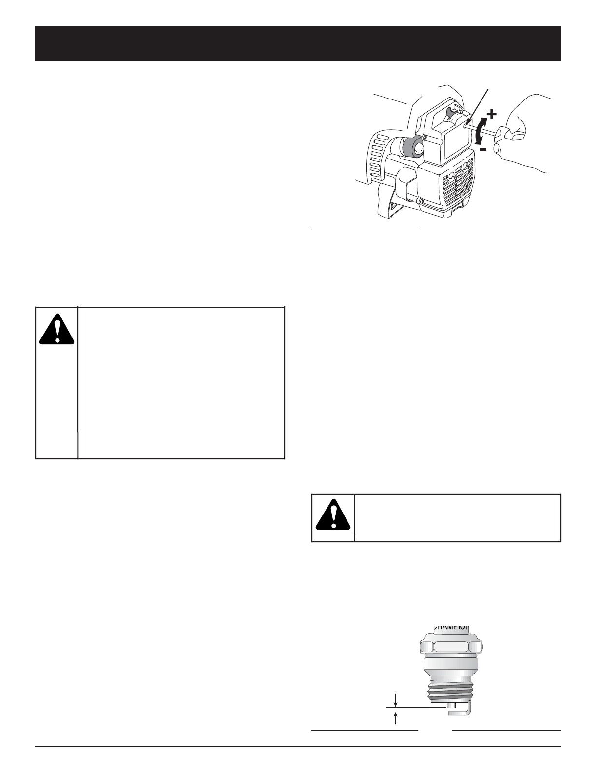
Adjust Idle Speed Screw
CARBURETOR ADJUSTMENT
The idle speed of the engine is adjustable through the air
filter/muffler cover (Fig. 23).
NOTE: Careless adjustments can seriously damage your
unit. An authorized service dealer should make
carburetor adjustments.
Checking the fuel mixture, cleaning the air filter, and
adjusting the idle speed should solve most engine
problems. If not and all of the following are true:
• the engine will not idle
• the engine hesitates or stalls on acceleration
• there is a loss of engine power
Have the carburetor adjusted by an authorized service dealer.
REPLACING THE SPARK PLUG
Use a Champion RDJ7Y spark plug, or equivalent. The
correct air gap is 0.020 inch (0.5 mm). Remove the plug
after every 25 hours of operation and check its condition.
1. Stop the engine and allow it to cool. Grasp the plug
wire firmly and pull it from the spark plug.
2. Clean around the spark plug. Remove the spark plug
from the cylinder head by turning a 5/8-inch socket
counterclockwise.
3. Replace a cracked, fouled or dirty spark plug. Set
the air gap at 0.020 in. (0.5 mm) using a feeler gauge
(Fig. 24).
4. Install a correctly-gapped spark plug in the cylinder
head. Tighten by turning the 5/8-inch socket
clockwise until snug.
If using a torque wrench torque to:
110-120 in.•lb. (12.3-13.5 N•m)
Do not over tighten.
0.020 in.
(0.5 mm)
Fig. 24
Idle Speed Screw
Fig. 23
If after checking the fuel mixture and cleaning the air
filter the engine still will not idle, adjust the idle speed
adjuster as follows.
1. Start the engine and let it run at the fast position for a
minute to warm up.
2. Move the throttle control to the idle position and let
the engine idle. If the engine stops, insert a small
phillips or flat blade screwdriver into the hole in the
air filter/muffler cover (Fig. 23). Turn the idle speed
adjuster in, clockwise, 1/8 of a turn at a time (as
needed) until the engine idles smoothly.
3. If the unit appears to be idling too fast, turn the idle
speed adjuster counterclockwise 1/8 of a turn at a
time (as needed), to reduce idle speed.
Do not sand blast,
scrape or clean
electrodes. Grit in the engine could damage
the cylinder.
WARNING:
This unit will need
to be running during
idle speed adjustment. Wear protective
clothing and observe all safety instructions
to prevent serious personal injury.
Also, DO NOT set unit on any surface
except a clean, hard area while starting or
performing any adjustments. Debris such
as gravel, sand, dust, grass, etc. could be
picked up by the air intake and thrown out
by the discharge opening, damaging unit,
property, or causing serious injury to
bystanders or operator.
WARNING:

18
MAINTENANCE AND REPAIR INSTRUCTIONS
CLEANING THE UNIT
Use a small brush to clean off the outside of the unit.
Do not use strong detergents. Household cleaners that
contain aromatic oils such as pine and lemon, and
solvents such as kerosene, can damage plastic housing
or handle. Wipe off any moisture with a soft cloth.
CLEANING THE VACUUM BAG
1. Empty the bag after each use to avoid deterioration
and obstructing air flow, which will reduce the
performance of the vacuum.
2. Wearing eye protection and a dust mask, clean the
bag as needed. Turn the bag inside out after initial
emptying and vigorously shake out dust and debris.
3. Wash the bag once a year or more often if needed:
a. Remove the vacuum bag.
b. Turn bag inside out.
c. Hang it up.
d. Hose it down thoroughly.
e. Hang to dry.
f. Turn bag right-side out and reinstall.
STORAGE
• Never store a fueled unit where fumes may reach an
open flame or spark.
• Allow the engine to cool before storing.
• Store the unit locked up to prevent unauthorized use
or damage.
• Store the unit in a dry, well-ventilated area.
• Store the unit out of the reach of children.
LONG TERM STORAGE
If you plan on storing the unit for an extended time, use
the following storage procedure:
1. Drain all fuel from the fuel tank into a container with
the same 2-cycle fuel mixture. Do not use fuel that
has been stored for more than 60 days. Dispose of
the old fuel/oil mix in accordance to Federal, State
and Local regulations.
2. Start the engine and allow it to run until it stalls. This
ensures that all fuel has been drained from the
carburetor.
3. Allow the engine to cool. Remove the spark plug and
put 1 oz. (30 ml) of any high quality motor oil or
2-cycle oil into the cylinder. Pull the starter rope
slowly to distribute the oil. Reinstall the spark plug.
NOTE: Remove the spark plug and drain all of the oil
from the cylinder before attempting to start the
unit after storage.
4. Thoroughly clean the unit and inspect it for any loose
or damaged parts. Repair or replace damaged parts
and tighten loose screws, nuts or bolts. The unit is
ready for storage.
TRANSPORTING
• Allow the engine to cool before transporting.
• Drain fuel from unit.
• Tighten fuel cap before transporting.
• Secure the unit while transporting.
To avoid serious
personal injury,
always turn your unit off and allow it to cool
before you clean or service it.
WARNING:
CLEARING A BLOCKED TUBE / IMPELLER
1. Press the On/Off Stop control down in the STOP (O)
position until the engine comes to a complete stop
(Fig. 10).
2. Disconnect the spark plug wire to prevent the unit
from starting.
To avoid serious
personal injury,
always wear gloves to protect yourself from
the impeller blades or other sharp objects.
WARNING:
To avoid serious
personal injury, be
sure the unit is off before cleaning or
performing any maintenance on it.
WARNING:
3. Remove the blower/vacuum tube and the vacuum bag.
4. Carefully remove material blocking the tube or
impeller. Inspect the blades to assure no damage has
occurred. Rotate the impeller blades by hand to
assure the blockage is completely cleared.
5. Reinstall the vacuum bag and blower/vacuum tube.
6. Reconnect the spark plug wire.

19
TROUBLESHOOTING
CAUSE ACTION
Old or improperly mixed fuel Drain gas tank / Add fresh fuel mixture
Air filter is plugged Replace or clean the air filter
Improper carburetor adjustment Take to an authorized service dealer for
carburetor adjustment
Fouled spark plug Replace or clean the spark plug
Plugged spark arrestor Clean or replace spark arrestor
CAUSE ACTION
Choke control is in the incorrect position Refer to the Starting/Stopping instructions
Throttle lever is in the incorrect position Refer to the Starting/Stopping instructions
Empty fuel tank Fill fuel tank with properly mixed fuel
Primer bulb wasn't pressed enough Press primer bulb fully and slowly 10 times
Engine flooded Use starting procedure with the choke lever in Position 3
Old or improperly mixed fuel Drain gas tank / Add fresh fuel mixture
Fouled spark plug Replace or clean the spark plug
Plugged spark arrestor Clean or replace spark arrestor
ENGINE WILL NOT START
ENGINE WILL NOT IDLE
ENGINE WILL NOT ACCELERATE
ENGINE LACKS POWER OR STALLS
CAUSE ACTION
Air filter is plugged Replace or clean the air filter
Old or improperly mixed fuel Drain gas tank / Add fresh fuel mixture
Improper carburetor adjustment Adjust according to the Carburetor Adjustments section
CAUSE ACTION
Old or improperly mixed fuel Drain gas tank / Add fresh fuel mixture
Improper carburetor adjustment Take to an authorized service dealer for
carburetor adjustment
Dirty air filter Clean or replace the air filter
Plugged spark arrestor Clean or replace spark arrestor
If further assistance is required, contact your authorized service dealer.
CAUSE ACTION
Bag full Empty bag, as described in Empty the Vacuum Bag
Blocked tube Clear the blockage as described in Clearing a Blocked
Tube/ Impeller
Blocked impeller Clear the blockage as described in Clearing a Blocked
Tube/ Impeller
Damaged impeller Take the unit to an authorized service dealer
UNIT WILL NOT BLOW OR VACUUM

20
SPECIFICATIONS
ENGINE*
Engine Type.......................................................................................................................................... Air-Cooled, 2-Cycle
Displacement............................................................................................................................................. 31 cc (1.9 cu. in)
Vacuum Operating RPM.................................................................................................................................... 6,800+ rpm
Blower Operating RPM....................................................................................................................................... 7,200+ rpm
Idle Speed RPM ...................................................................................................................................... 3,200 - 4,400 rpm
Ignition Type.......................................................................................................................................................... Electronic
On/Off Stop Control....................................................................................................................................... Rocker Switch
Spark Plug Gap.................................................................................................................................... 0.020 inch (0.5 mm)
Lubrication................................................................................................................................................... Fuel/Oil Mixture
Fuel/Oil Ratio................................................................................................................................................................. 40:1
Carburetor....................................................................................................................................... Diaphragm, All-Position
Starter............................................................................................................................................................... Auto Rewind
Muffler..................................................................................................................................................... Baffled with Guard
Fuel Tank Capacity................................................................................................................................. 13 ounces (384 ml)
BLOWER / VACUUM*
Throttle Control........................................................................................................................................... Finger-Tip Lever
Blower Velocity............................................................................................................................. up to 200 mph (322 kmh)
Blower Air Output ........................................................................................................................ up to 425 cfm (12.1 cmm)
Mulching Ratio...................................................................................................................................................... up to 10:1
Vacuum Bag Capacity................................................................................................................... 1.5 bushels (52.8 Liters)
Weight (no fuel, with blower tube) ................................................................................................................11.4 lb. (5.2 kg)
*All specifications are based on the latest product information available at the time of printing. We reserve the right to
make changes at any time without notice.

21
California / EPA Emission Control Warranty Statement
Your Warranty Rights and Obligations
The California Air Resources Board, the Environmental Protection Agency and MTD LLC (MTD) are pleased to explain
the emission control system warranty on your 2000 and later small off-road engine. New small off-road engines must be
designed, built and equipped to meet stringent anti-smog standards. MTD must warrant the emission control system on
your small off-road engine for the periods of time listed below provided there has been no abuse, neglect or improper
maintenance of your small off-road engine.
Your emission control system may include parts such as the carburetor or fuel-injected system, the ignition system, and
catalytic converter. Also included may be hoses, belts, connectors and other emission-related assemblies.
Where a warrantable condition exists, MTD will repair your small off-road engine at no cost to you including diagnosis,
parts and labor.
The 2000 and later small off-road engines are warranted for two years. If any emission-related part on your engine is
defective, the part will be repaired or replaced by MTD.
Owners Warranty Responsibilities
• As the small off-road engine owner, you are responsible for the performance of the required maintenance listed in your
operator’s manual. MTD recommends that you retain all receipts covering maintenance on your small off-road engine,
but MTD cannot deny warranty solely for the lack of receipts or for your failure to ensure the performance of all
scheduled maintenance.
• As the small off-road engine owner, you however should be aware that MTD may deny you warranty coverage if your
small off-road engine or a part has failed due to abuse, neglect, improper maintenance or unapproved modifications.
• You are responsible for presenting your small off-road engine to a MTD Authorized Service Center as soon as a
problem exists. The warranty repairs should be completed in a reasonable amount of time, not to exceed 30 days.
If you have any questions regarding your warranty rights and responsibilities, you should call 1-800-345-8746.
Manufacturer’s Warranty Coverage
• The warranty period begins on the date the engine or equipment is delivered to the retail purchaser.
• The manufacturer warrants to the initial owner and each subsequent purchaser, that the engine is free from defects in
material and workmanship which cause the failure of a warranted part for a period of two years.
• Repair or replacement of warranted part will be performed at no charge to the owner at an Authorized MTD Service
Center. For the nearest location please contact MTD at: 1-800-345-8746.
• Any warranted part which is not scheduled for replacement, as required maintenance or which is scheduled for only
for regular inspection to the effect of “Repair or Replace as Necessary” is warranted for the warranty period. Any
warranted part which is scheduled for replacement as required maintenance will be warranted for the period of time up
to the first scheduled replacement point for that part.
• The owner will not be charged for diagnostic labor which leads to the determination that a warranted part is defective,
if the diagnostic work is performed at an Authorized MTD Service Center.
• The manufacturer is liable for damages to other engine components caused by the failure of a warranted part still
under warranty.
• Failures caused by abuse, neglect or improper maintenance are not covered under warranty.
• The use of add-on or modified parts can be grounds for disallowing a warranty claim. The manufacturer is not liable to
cover failures of warranted parts caused by the use of add-on or modified parts.
• In order to file a claim, go to your nearest Authorized MTD Service Center. Warranty services or repairs will be
provided at all Authorized MTD Service Centers.
• Any manufacturer approved replacement part may be used in the performance of any warranty maintenance or repair
of emission related parts and will be provided without charge to the owner. Any replacement part that is equivalent in
performance or durability may be used in non-warranty maintenance or repair and will not reduce the warranty
obligations of the manufacturer
• The following components are included in the emission related warranty of the engine, air filter, carburetor, primer, fuel
lines, fuel pick up/ fuel filter, ignition module, spark plug and muffler.

MANUFACTURER’S LIMITED WARRANTY FOR:
No implied warranty, including any implied warranty of
merchantability or fitness for a particular purpose,
applies after the applicable period of express written
warranty above as to the parts as identified. No other
express warranty or guaranty, whether written or oral,
except as mentioned above, given by any person or
entity, including a dealer or retailer, with respect to any
product shall bind MTD. During the period of the
Warranty, the exclusive remedy is repair or replacement
of the product as set forth above. (Some states do not
allow limitations on how long an implied warranty lasts, so
the above limitation may not apply to you.)
The provisions as set forth in this Warranty provide the
sole and exclusive remedy arising from the sales. MTD
shall not be liable for incidental or consequential loss or
damages including, without limitation, expenses incurred
for substitute or replacement lawn care services, for
transportation or for related expenses, or for rental
expenses to temporarily replace a warranted product.
(Some states do not allow limitations on how long an implied
warranty lasts, so the above limitation may not apply to you.)
In no event shall recovery of any kind be greater than the
amount of the purchase price of the product sold. Alteration
of the safety features of the product shall void this Warranty.
You assume the risk and liability for loss, damage, or injury
to you and your property and/or to others and their property
arising out of the use or misuse or inability to use the
product.
This limited warranty shall not extend to anyone other than
the original purchaser, original lessee or the person for whom
it was purchased as a gift.
How State Law Relates to this Warranty: This warranty
gives you specific legal rights, and you may also have other
rights which vary from state to state.
To locate your nearest service dealer dial 1-800-345-8746
in the United States or 1-800-668-1238 in Canada.
MTD LLC
P.O. Box 361131
Cleveland, OH 44136-0019
The limited warranty set forth below is given by MTD
LLC (“MTD”) with respect to new merchandise purchased and
used in the United States, its possessions and territories.
MTD warrants this product against defects in material and
workmanship for a period of two (2) years commencing on the
date of original purchase and will, at its option, repair or
replace, free of charge, any part found to be defective in
material or workmanship. This limited warranty shall only apply
if this product has been operated and maintained in
accordance with the Operator’s Manual furnished with the
product, and has not been subject to misuse, abuse,
commercial use, neglect, accident, improper maintenance,
alteration, vandalism, theft, fire, water or damage because of
other peril or natural disaster. Damage resulting from the
installation or use of any accessory or attachment not
approved by MTD for use with the product(s) covered by this
manual will void your warranty as to any resulting damage. This
warranty is limited to ninety (90) days from the date of original
retail purchase for any MTD product that is used for rental or
commercial purposes, or any other income-producing purpose.
HOW TO OBTAIN SERVICE: Warranty service is available,
WITH PROOF OF PURCHASE THROUGH YOUR LOCAL
AUTHORIZED SERVICE DEALER. To locate the dealer in your
area, please check for a listing in the Yellow Pages or contact
the Customer Service Department of MTD LLC by calling
1-800-345-8746 or writing to P.O. Box 361131, Cleveland OH
44136-0019 or if in Canada call 1-800-668-1238. No product
returned directly to the factory will be accepted unless prior
written permission has been extended by the Customer
Service Department of MTD LLC.
This limited warranty does not provide coverage in the
following cases:
A. Tune-ups - Spark Plugs, Carburetor Adjustments, Filters.
B. Wear items - Bump Knobs, Outer Spools, Cutting Line,
Inner Reels, Starter Pulley, Starter Ropes, Drive Belts.
C. MTD does not extend any warranty for products sold or
exported outside of the United States of America, its
possessions and territories, except those sold through
MTD’s authorized channels of export distribution.
MTD reserves the right to change or improve the design of
any MTD Product without assuming any obligation to modify
any product previously manufactured.
Manuel de l'utilisateur
YM320BV
Souffleuse
Aspirateur
Déchiqueteuse
2-temps
P/N 769-01400 (1/05)
IMPRIMÉ AUX ÉTATS-UNIS
MANUEL IMPORTANT À NE PAS JETER
F2
INTRODUCTION
Copiez le numéro
de série ici :
Copiez le numéro de
modèle / pièce mère ici :
TOUS NOS REMERCIEMENTS
Nous vous remercions d'avoir acheté ce produit de
qualité. Cet outil mécanique de plein air moderne est
conçu pour vous rendre service pendant longtemps. Il
vous sauvera beaucoup de temps comme vous pourrez
vous en rendre compte. Ce manuel de l'utilisateur
comporte un mode d'emploi facile à comprendre. Prenez
soin de lire le manuel au complet et suivez toutes ses
instructions à la lettre afin de conserver votre nouvel outil
mécanique de plein air en excellent état de
fonctionnement.
RÉFÉRENCES, ILLUSTRATIONS ET
SPÉCIFICATIONS RELATIVES AU PRODUIT
Toutes les informations, illustrations et spécifications
contenues dans ce manuel tiennent compte des dernières
informations techniques disponibles au moment de
mettre sous presse. Nous nous réservons le droit d'y
apporter des modifications à tout moment, sans préavis.
Copyright© 2005 MTD SOUTHWEST INC., Tous droits
réservés.
NFORMATIONS D’ENTRETIEN
Tout entretien effectué sur cet appareil pendant et après
la période de garantie doit être fait par un
concessionnaire agréé uniquement. Obtenez la liste des
concessionnaires agréés appelez le 1-800-345-8746
aux
États-unis, ou le
1-800-668-1238
au Canada
. Pour de plus
amples informations à propos de votre appareil, visitez
www.Yardman.com.
NE RETOURNEZ PAS L'APPAREIL AU DÉTAILLANT
CHEZ QUI VOUS L'AVEZ ACHETÉ. TOUT SERVICE
SOUS GARANTIE NÉCESSITE UNE PREUVE D'ACHAT.
Avant d'assembler votre nouvel équipement, repérez la
plaque signalétique de l'appareil et copiez ses
informations dans l'espace ci-dessous. Ces informations
sont essentielles si vous désirez obtenir de l'aide auprès
de notre service technique ou d'un distributeur agréé. Un
exemple de plaque signalétique est présenté ci-dessous.
Prenez soin de lire et de bien comprendre ce manuel
avant de démarrer ou de faire fonctionner cet équipement.
CE PRODUIT EST COUVERT PAR UN OU PLUSIEURS
BREVETS AMÉRICAINS, ET D’AUTRES SONT EN
INSTANCE.
TABLE DES MATIÈRES
Service technique . . . . . . . . . . . . . . . . . . . . . . . . . . .2
Consignes de sécurité . . . . . . . . . . . . . . . . . . . . . . .3
Familiarisez-vous avec votre appareil . . . . . . . . . . .7
Instructions de montage . . . . . . . . . . . . . . . . . . . . . .8
Informations sur l'huile et le carburant . . . . . . . . . .11
Instructions de démarrage et d'arrêt . . . . . . . . . . .12
Mode d'emploi . . . . . . . . . . . . . . . . . . . . . . . . . . . .13
Entretien et réparations . . . . . . . . . . . . . . . . . . . . .15
Accessoires/pièces de rechange . . . . . . . . . . . . . .19
Nettoyage et entreposage . . . . . . . . . . . . . . . . . . .19
Tableau de dépannage . . . . . . . . . . . . . . . . . . . . . .20
Caractéristiques . . . . . . . . . . . . . . . . . . . . . . . . . . .21
Garantie . . . . . . . . . . . . . . . . . . . . . . . . . . . . . . . . .24
Liste des pièces . .Intérieure de la Couverture Arrière
PARE-ÉTINCELLES
REMARQUE : à l'intention des utilisateurs opérant
dans les terres forestières des États-Unis et dans les
états de Californie, du Maine, de l'Orégon et de
Washington. Toutes les terres forestières des États-Unis
et de l'état de Californie (Codes sur les ressources
publiques 4442 et 4443), de l'Orégon et de Washington
exigent de par la loi que certains moteurs à combustion
interne utilisés dans des zones couvertes de taillis ou
d'herbe soient équipés d'un pare-étincelles en parfait état
de fonctionnement, ou qu'ils soient conçus, équipés et
entretenus pour la prévention des incendies. Renseignezvous auprès des autorités de votre province ou de votre
municipalité concernant la réglementation en vigueur.
Vous pourriez être passible d'une amende ou être tenu
responsable si vous ne respectez pas cette
réglementation. Cet appareil est équipé d'un pareétincelles en usine. Si l'écran pare-étincelles, réf.
753-04689, doit être remplacé, communiquez avec le
service technique.
AVERTISSEMENT
LES GAZ D'ÉCHAPPEMENT DU MOTEUR DE
CET APPAREIL CONTIENNENT DES PRODUITS
CHIMIQUES CONSIDÉRÉS PAR L'ÉTAT DE
CALIFORNIE COMME POUVANT CAUSER LE
CANCER, DES MALFORMATIONS
CONGÉNITALES OU D'AUTRES EFFETS NOCIFS
SUR L'APPAREIL DE REPRODUCTION.
AVERTISSEMENT DE LA PROPOSITION 65 DE
CALIFORNIE
Numéro de modèle
Numéro de série
Numéro de pièce mère
MODEL :
S/N :
ITEM :
F3
CONSIGNES DE SÉCURITÉ
LIRE TOUTES LES INSTRUCTIONS
AVANT UTILISATION
• Lire les instructions attentivement. Se familiariser avec
les commandes et l’utilisation correcte de cet outil.
• Ne pas utiliser l’outil si vous êtes fatigué, malade ou
sous l’effet de l’alcool, de drogues ou de médicaments.
• Les enfants de moins de 15 ans ne doivent pas utiliser
l’outil, exception faite des adolescents sous
surveillance d’un adulte.
• Toutes les protections et tous les accessoires de
sécurité doivent être en place avant d’utiliser l’outil.
• Inspecter l’outil avant utilisation. Remplacer les pièces
endommagées. Regarder s’il y a des fuites de
carburant. Vérifier que toute la boulonnerie est bien
serrée et qu’aucune pièce ne manque. Remplacer les
pièces de l’accessoire de coupe fêlées, ébréchées ou
endommagées. Ne pas utiliser l’outil si des pièces
sont desserrées ou endommagées.
• Éloigner les personnes enfants et animaux de la zone
de travail. Prévoir une zone de sécurité dont le rayon
est d’au moins 15 m (50 pi) tout en restant conscient
que des objets risquent d’être projetés au-delà de
cette zone et blesser quelqu’un. Il est recommandé à
toute personne se trouvant à proximité de porter des
lunettes de sécurité. Arrêter immédiatement le moteur
si quelqu’un s’approche.
• Inspecter soigneusement la zone de travail avant de
démarrer l’outil. Éliminer tous les débris tels que
morceaux de verre, fil de fer, etc.
AVERTISSEMENTS DE SÉCURITÉ CONCERNANT
LES OUTILS À MOTEUR À ESSENCE
• Ne conserver le carburant que dans des récipients
spécialement conçus et homologués pour le stockage
de ce type de produit.
• Éviter de créer une source d’allumage pour le carburant
répandu. Ne pas lancer le moteur avant que toutes les
vapeurs se soient dissipées, afin d’éviter de créer une
source d’allumage pour le carburant répandu.
• Toujours arrêter le moteur et le laisser refroidir avant
faire l’appoint de carburant. Ne jamais retirer le
bouchon du réservoir de carburant ou faire l’appoint
pendant que le moteur est chaud. Ne jamais utiliser
l’outil sans que le bouchon du réservoir soit bien en
place. Desserrer le bouchon lentement afin de relâcher
la pression du réservoir.
• Mélanger et ajoutez le carburant dans un endroit bien
aéré et propre, en plein air, à l’abri des sources
d’étincelles ou flammes vives. Ne retirer (lentement) le
bouchon du réservoir d’essence qu’après avoir arrêté
le moteur. Ne pas fumer pendant l’approvisionnement
ou le mélange de carburant. Essuyer immédiatement
le carburant répandu sur l’outil.
SYMBOLE SIGNIFICATION
SYMBOLE SIGNIFICATION
•
IMPORTANTES CONSIGNES DE SÉCURITÉ•
Les symboles de sécurité attirent votre attention sur
des dangers potentiels. Ces symboles et leurs détails
explicatifs méritent que vous les lisiez et compreniez
bien. Les avertissements de sécurité ne peuvent éviter
les dangers de par eux-mêmes. Les consignes ou
mises en garde qu'ils donnent ne remplacent pas des
mesures préventives appropriées contre les accidents.
REMARQUE: donne des informations ou des
instructions vitales pour le fonctionnement ou
l'entretien de l'équipement.
le non-
respect d’un
avertissement peut causer dommages matériels
ou blessures graves pour tous. Respectez les
consignes de sécurité afin de réduire les risques
d'incendie, d'électrocution et de blessures.
AVERTISSEMENT :
le non-respect d’un
avertissement peut
causer dommages matériels ou blessures
graves pour tous. Respectez les consignes de
sécurité afin de réduire les risques d'incendie,
d'électrocution et de blessures.
DANGER:
le non-
respect
d’un avertissement peut causer dommages
matériels ou blessures graves pour tous.
Respectez toujours les consignes de sécurité
afin de réduire les risques d'incendie,
d'électrocution et de blessures.
MISE EN GARDE:
indique un danger, un avertissement ou une
mise en garde. Soyez vigilant afin d'éviter toute
blessure grave. Ce symbole peut être combiné
à d'autres symboles ou pictogrammes.
ALERTE DE SÉCURITÉ:
Lisez le(s) manuel(s) de l'utilisateur et suivez tous
les avertissements et consignes de sécurité.
Vous pourriez à défaut entraîner des blessures
graves pour vous ou d'autres personnes.
SI VOUS AVEZ DES QUESTIONS, APPELEZ LE 1-800-
345-8746 AUX ÉTATS-UNIS, OU LE 1-800-668-1238 AU
CANADA
l'essence
est
extrêmement inflammable et ses vapeurs
peuvent exploser si on y met le feu. Veuillez
prendre les précautions suivantes.
AVERTISSEMENT:

F4
CONSIGNES DE SÉCURITÉ
• Éloigner l’outil d’au moins 9 m (30 pi) du point
d’approvisionnement en carburant avant de démarrer
le moteur. Ne pas fumer et éloigner toute source
d’étincelles ou de flammes vives du point
d’approvisionnement ou d’utilisation de l’outil.
PENDANT L’UTILISATION
• Ne jamais démarrer ou utiliser l’outil dans un local clos.
L’inhalation des vapeurs d’échappement peut être
mortelle. N’utiliser l’outil qu’à l’extérieur, dans un
endroit bien aéré.
• Pour réduire les risques de blessures par des objets
projetés, porter des lunettes de sécurité conformes à la
norme ANSI Z87.1.
• Ne jamais utiliser l’outil s’il n’est pas équipé des
accessoires nécessaires. Ne jamais utiliser l’outil sans
les tubes de souffleuse ou le sac d’aspirateur (suivant
le modèle). S’assurer que la fermeture à glissière du
sac est complètement fermée.
•Pour réduire les risques de perte de l’ouïe causée par
le niveau de bruit, toujours porter une protection
auditive lors de l’utilisation.
• Porter des pantalons épais et longs, des bottes, des
gants et une chemise à manches longues. Ne pas porter
de shorts ou sandales et ne pas marcher pieds nus.
• Ne pas porter de gants en caoutchouc ou isolés pour
éviter les décharges d’électricité statique lors de
l’utilisation.
• Pour éviter des risques de blessures, ne pas porter de
vêtements amples, bijoux, foulards et autres, qui
pourraient être happés par les pièces en rotation. Les
cheveux longs doivent être couverts ou maintenus audessus des oreilles.
• Porter un masque facial lors du travail dans les
endroits poussiéreux. Les chemises à manches
longues sont recommandées.
• N’utiliser l’outil qu’en plein jour ou sous bon éclairage
artificiel.
•Garder l’extérieur de l’outil exempt d’huile et de carburant.
• Éviter tout démarrage accidentel. Toujours se tenir en
position de démarrage avant de tirer la corde de
démarrage. L’opérateur et l’outil doivent tous deux être
en position d’équilibre lors du démarrage. Voir les
instructions de Démarrage et arrêt.
• L’outil doit toujours être posé sur une surface propre et
ferme. Les matériaux tels que le gravier, le sable, la
poussière, l’herbe, etc. peuvent être aspirés par
l’admission d’air et projetés par la sortie de l’outil, ce
qui peut endommager l’outil, causer des dégâts
matériels et des blessures graves à l’utilisateur ou aux
personnes se trouvant à proximité.
• Toujours utiliser un outil adéquat pour l’application. Ne
pas utiliser cet outil pour un usage pour lequel il n’est
pas conçu.
• Ne pas forcer l’outil. Il fonctionnera plus efficacement
et sera moins dangereux si sa capacité nominale n’est
pas dépassée.
• Ne pas essayer de travailler hors de portée ou en se
tenant sur une surface instable, telle qu’une échelle, un
arbre, un toit, une pente abrupte, un toit, etc. Toujours
se tenir bien campé, en position d’équilibre.
• Toujours tenir l’outil fermement pendant l’utilisation.
• Garder les mains, le visage et les pieds à l’écart des
pièces en mouvement. Ne pas essayer de toucher ou
d’arrêter l’hélice en rotation. Ne pas utiliser l’outil si les
dispositifs de protection ne son pas en place.
• Ne jamais introduire quoi que ce soit dans les
ouvertures. Garder les ouvertures dégagées, exemptes
de poussières et de débris ou autres risquant de
réduire la circulation d’air.
• Ne toucher ni le moteur, ni le silencieux. Ces pièces
deviennent très chaudes pendant le fonctionnement.
Elles restent brûlantes pendant quelques temps après
l’arrêt.
• Ne pas faire fonctionner le moteur à un régime plus
qu’il n’est nécessaire pour s’acquitter de la tâche. Ne
pas faire tourner le moteur à haut régime à vide.
• Toujours arrêter le moteur si le travail est interrompu
ou avant de se déplacer d’un endroit à un autre.
• Arrêter le moteur et débrancher avant toute opération
d’entretien ou réparation et avant d’installer ou retirer
les tubes de souffleuse ou accessoires d’aspirateur. Le
moteur et les pales de l’hélice doivent être parvenus à
l’arrêt complet pour éviter tout danger de blessure par
les pièces en rotation.
• N'utilisez que des pièces de équipement original
rechange et accessoires d’origine du fabricant pour cet
appareil. Elles sont disponibles auprès de votre
concessionnaire agréé. L'utilisation de pièces ou
accessoires autres que ceux de éqiupement original
peut causer des blessures graves, endommager
l’appareil et annuler sa garantie.
• Ne jamais utiliser cet outil pour répandre des produits
chimiques, engrais ou matériaux pouvant contenir des
substances toxiques.
• Afin de réduire les risques d’incendie, remplacer tout
silencieux ou pare-étincelles défectueux et garder le
moteur et le silencieux exempts d’herbe, de feuilles et
d’accumulation excessive de graisse ou de calamine.

F5
LORS DE L’UTILISATION EN SOUFFLEUSE
• Ne jamais diriger le tube de la souffleuse vers des
personnes, animaux domestiques ou fenêtres. Toujours
souffler les débris en direction opposée des personnes,
animaux domestiques et fenêtres. Redoubler de
prudence lors du travail à proximité d’objets massifs
tels que des arbres, véhicules, murs, etc.
LORS DE L’UTILISA TION EN ASPIRATEUR
• Éviter les situations où le sac d’aspirateur pourrait
s’enflammer. Ne pas utiliser à proximité de flammes
vives, Ne pas aspirer les cendres chaudes de
cheminées, foyers, tas de brouissalles, etc. Ne pas
aspirer de mégots de cigarettes ou de cigares sans
s’être assuré qu’ils sont complètement froids.
• Cet outil est conçu pour aspirer des matériaux secs,
tels que des feuilles, de l’herbe, des brindilles et
morceaux de papier. Ne pas essayer d’aspirer des
matériaux mouillées ni de l’eau, ce qui pourrait
endommager la souffleuse/aspirateur. Ne pas aspirer
de morceaux de métal, de verre, etc., pour éviter
d’endommager l’hélice.
AUTRES AVERTISSEMENTS DE SÉCURITÉ
• Toujours débrancher la bougie avant de travailler sur
les pièces mobiles.
•Ne jamais remiser l’outil rempli de carburant à
l’intérieur d’un bâtiment où les vapeurs peuvent
atteindre une source de flammes vives (une veilleuse
par exemple) ou d’étincelles (commutateurs, moteurs
électriques, etc.
• Laisser le moteur refroidir avant de remiser ou
transporter l’outil. Bien arrimer l’outil pour le transport.
• Remiser l’outil dans un endroit sec pouvant être
verrouillé ou en hauteur afin d’empêcher des
dommages ou un usage non autorisé. Garder l’outils
hors de portée des enfants.
• Ne jamais immerger l’outil et ne jamais l’arroser avec
de l’eau ou tout autre liquide. Garder les poignées
sèches, propres et exemptes de débris. Nettoyer après
chaque usage. Voir les sections Nettoyage et
Remisage.
• Conserver ces instructions. Les consulter fréquemment
et les utiliser pour instruire d’autres utilisateurs. Si
l’outil est prêté, il doit être accompagné de ces
instructions.
REMARQUE SPÉCIALE: L’exposition à des vibrations
due à un usage prolongé d’outils à essence peut
entraîner une lésion des vaisseaux sanguins ou des nerfs
au niveau des doigts, mains et articulations des
personnes prédisposées aux troubles de la circulation et
aux tuméfactions anormales. L’utilisation prolongée en
eau froide a été reliée aux lésions des vaisseaux
sanguins chez des personnes normalement en santé. En
cas de symptômes tel qu’engourdissement, douleur,
perte de force, changement de couleur ou de texture de
la peau, perte de sensation dans les doigts, les mains ou
les articulations, cessez l’utilisation de l’appareil et
consultez un médecin. Un système anti-vibration ne
garantit pas que ce genre de problème puisse être évité.
Les individus utilisant des outils mécaniques de manière
régulière doivent surveiller attentivement leur état
physique et celui de l’appareil.
CONSERVER CES
INSTRUCTIONS
CONSIGNES DE SÉCURITÉ

F6
CONSIGNES DE SÉCURITÉ
SYMBOLES DE SÉCURITÉ ET INTERNATIONAUX
Ce manuel de l'utilisateur décrit les symboles et pictogrammes de sécurité et internationaux pouvant apparaître sur ce
produit. Consultez le manuel de l'utilisateur pour les informations concernant la sécurité, le montage, le fonctionnement,
l'entretien et les réparations.
SYMBOLE SIGNIFICATION
• SYMBOLE ALERTE DE
SÉCURITÉ
Indique un danger, un avertissement
ou une mise en garde. Ce symbole
peut être combiné à d'autres symboles
ou pictogrammes.
•AVERTISSEMENT - LISEZ LE
MANUEL DE L'UTILISATEUR
Lisez le manuel de l'utilisateur et suivez
tous les avertissements et consignes
de sécurité. Vous pourriez à défaut
entraîner des blessures graves pour
vous ou d'autres personnes.
• PORTEZ DES PROTECTIONS
(YEUX ET OREILLES)
AVERTISSEMENT: les objets projetés
et les bruits forts peuvent endommager
la vue et l’ouïe. Portez une visière de
norme ANSI Z87.1-1989 et des
protège-oreilles pendant l'utilisation.
• ÉLOIGNEZ LES SPECTATEURS
AVERTISSEMENT: éloignez tout
spectateur, les enfants et les animaux
domestiques en particulier, d'au moins
15 m (50 pi) de la zone de coupe.
• CARBURANT SANS PLOMB
Utilisez toujours du carburant sans
plomb frais et propre.
• NIVEAU D'HUILE
Voir le manuel de l'utilisateur pour le
type d'huile approprié.
• LES OBJETS PROJETÉS ET LA
TÊTE ROT ATIVE PEUVENT CAUSER
DES BLESSURES GRAVES
AVERTISSEMENT: Tenez-vous à
l'écart de la sortie de souffleuse. Ne
dirigez jamais la souffleuse vers vous
ou vers les autres. La souffleuse peut
projeter des objets. Ne faites pas
fonctionner l'appareil sans les
accessoires et protections nécessaires
.
SYMBOLE SIGNIFICATION
• COMMANDE MARCHE/ARRÊT
STOP
ALLUMAGE / DÉMARRAGE / MARCHE
• COMMANDE MARCHE/ARRÊT
STOP
ARRÊT ou STOP
•AVERTISSEMENT SURFACE
CHAUDE
Ne touchez pas un silencieux ou un
cylindre chaud. Vous pourriez vous
brûler. Ces pièces deviennent très
chaudes à l'utilisation. Elles restes
chaudes brièvement après l'arrêt.
• ETRANGLEUR
1 • Position d’étranglement MAXIMUM
2 •
Position d’étranglement PARTIEL
3 • Position
de MARCHE
• SOUFFLEUSES – LES LAMES
ROTATIVES PEUVENT INFLIGER
DES BLESSURES GRAVES
AVERTISSEMENT : arrêter le
moteur et laisser l’hélice parvenir à
l’arrêt complet avant d’installer ou
de changer les tubes ou le sac et
avant toute opération de nettoyage,
d’entretien ou de réparation.
• MANETTE DES GAZ
"HAUTE" vitesse ou vitesse
"MAXIMUM"
• MANETTE DES GAZ
"RALENTI" ou vitesse "BASSE" ou
"MINIMUM"
12
3

F7
CONSIGNES DE SÉCURITÉ
USAGE
Comme souffleuse :
• Nettoyage de cours, garages, chemins, porches,
terrasses, autour des murs, clôtures, etc.
Comme aspirateur :
• Ramassage de feuilles, de débris légers, etc.
Tube de souffleuse
Entrée de
souffleuse
Crochet du sac
d'aspirateur
Bouchon du
carburant
Manette des gaz
Bougie
Poignée de la corde
de démarrage
Commande
Marche/Arrêt Stop
FAMILIARISEZ-VOUS AVEC L’APPAREIL
Montage comme souffleuse
la porte
d’aspiration
Poignée antérieure
Tubes
d’aspirateur
Montage comme aspirateur
Sac d'aspirateur
Fermeture éclair
du sac d'aspirateur
Amorceur
Levier
d'étrangleur
Couvercle du filtre à
air/silencieux
Silencieux
Entrée de souffleuse/aspirateur
Poignée Arriére

F8
INSTRUCTIONS DE MONTAGE
Languettes
Tube d’aspiration
supérieur
Tube d’aspiration inférieur
MONTAGE COMME SOUFFLEUSE
Montage du tube de soufflage
REMARQUE :Si l’appareil a été assemblé comme
aspirateur, retirez toutes les pièces propres à
l’aspirateur et rangez-les en lieu sûr pour un
usage ultérieur.
Installation
• Enfoncez le tube de soufflage sur la sortie de
l’aspirateur jusqu’à ce que les deux languettes
émettent un déclic (Fig. 1).
Retrait
• Retirez le tube de soufflage en appuyant sur les deux
languettes en même temps et en tirant la souffleuse
(Fig. 1).
MONTAGE COMME ASPIRATEUR
Pour assembler la machine comme un aspirateur,
commencez par retirer le tube du souffleur. Consultez le
chapitre précédent.
Montage du tube d’aspiration
NOTE :Si l’appareil a été assemblé comme souffleuse,
retirez toutes les pièces propres à la souffleuse
et rangez-les en lieu sûr pour un usage ultérieur.
Installation
1. Aligner la flèche du tube d’aspiration inférieur sur
celle du tube d’aspiration supérieur (Fig. 2).
2. Saisir fermement le tube d’aspiration inférieur à deux
mains et l’emboîter dans le tube supérieur. Tourner le
tube inférieur vers la droite jusqu’à ce qu’il s’encliquette.
(Pour que l’assemblage soit correct, le point du tube
inférieur doit s’aligner sur celui du tube supérieur).
3. Retournez la machine pour qu’elle soit dressée sur le
bouclier de l’échappement. Le devant de la machine et
la porte d’aspiration devraient vous faire face (Fig. 3).
Fig. 1
Fig. 2
Pour
éviter des
blessures graves et ne pas endommager
l'appareil utilisé comme souffleuse, installez
le tube de soufflage.
AVERTISSEMENT :
Pour
éviter des
blessures graves et ne pas endommager
l'appareil utilisé comme aspirateur, installez
toujours les tubes et le sac d’aspirateur, et
assurez-vous que la fermeture éclair du sac
est fermée.
AVERTISSEMENT :
Pour
éviter des
blessures graves, stoppez le moteur et
laissez l’hélice s’arrêter avant d’installer ou
de changer les tubes.
AVERTISSEMENT :
Pour
éviter des
blessures graves, stoppez le moteur et
laissez l’hélice s’arrêter avant de fixer ou
d’enlever les tubes.
AVERTISSEMENT :
Fig. 3
la porte
d’aspiration

F9
INSTRUCTIONS DE MONTAGE
4. Insérez un tournevis plat dans la fente à l’extrémité
inférieure de la porte de l’aspirateur. Touchez le
verrouillage de la porte d’aspiration et poussez vers
l’intérieur et vers le haut (Fig. 4). Tirez alors sur la
porte d’aspiration et maintenez-la ouverte.
5. Tandis que vous gardez la porte d’aspiration
ouverte, trouvez le tube d’aspiration assemblé
(assemblé dans l’étape 2). Positionnez le tube pour
que la surface soit en face de la porte d’aspiration.
Les rainures sur le côté du tube s’aligneront avec les
petites pattes dans l’admission de l’hélice (Fig.5). De
l’extérieur, alignez la petite flèche sur le tube
d’aspiration avec le point sur l’admission de l’hélice.
6. Insérez le tube d’aspiration en le poussant
fermement et saisissez-le à deux mains. Tournez
dans le sens des aiguilles d’une montre aussi loin
que possible jusqu’à ce qu’il se verrouille en place.
Lorsque correctement assemblé, le point sur le tube
d’aspiration s’alignera avec le point sur l’admission
de l’hélice.
Retrait
1. Détachez le sac.
2. Retirez le sac d'aspirateur en appuyant sur les deux
languettes du coude du sac en même temps et en
tirant l’aspirateur (Fig. 6).
3. Installez le tube du souffleur pour assembler la
machine comme un souffleur.
4. Assurez-vous que la porte d’aspiration est
solidement fermée.
Verrouillage
Fig. 4
Installation le sac d'aspirateur
7. Enfoncez le tube du sac d'aspirateur sur la sortie de
souffleuse et poussez jusqu'à ce que les deux
languettes émettent un déclic (Fig. 6).
8. Attachez le sac de l’aspirateur au crochet du sac de
l’aspirateur situé en dessous de la machine.
Fig. 6
Fente dans la
porte d’aspiration
Admission de
l’hélice
Rainure du tube
d’aspiration
Fig. 5
Crochet du sac de l’aspirateur
Coude
Languettes
Méplat
Languettes
N’opérez
jamais la
machine en configuration souffleur sans que
la porte d’aspiration soit fermement en place
et verrouillée.
AVERTISSEMENT :
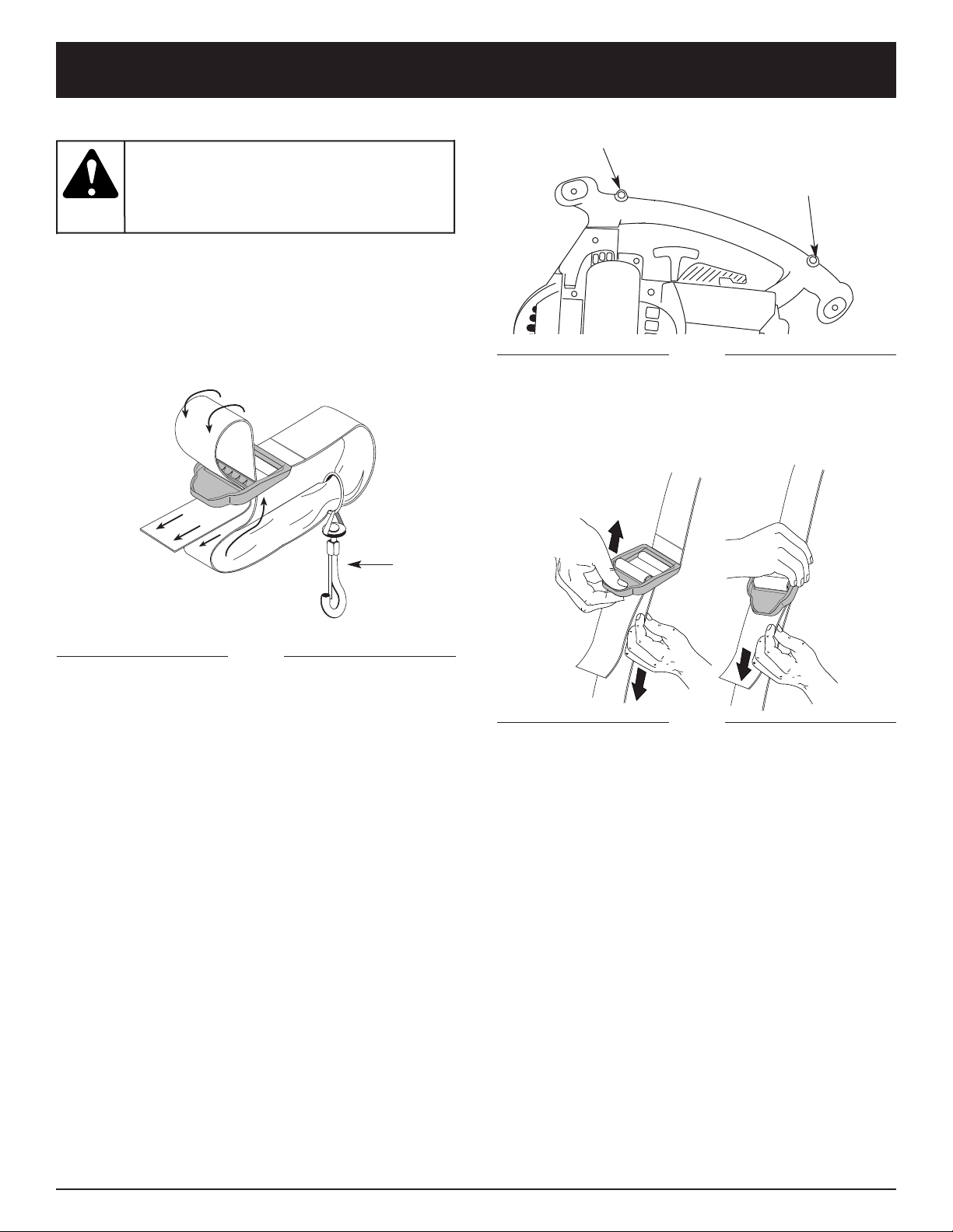
F10
INSTRUCTIONS DE MONTAGE
Fig. 9
4.Réglez la longueur en fonction de la taille de
l'opérateur. Tirez la languette pour rallonger, ou tirez la
bande pour raccourcir (Fig. 9).
INSTALLATION DU HARNAIS
1.Faites passer la bande au centre de la boucle.
2.Tirez la bande par-dessus la traverse et à travers la
fente de la boucle (Fig. 7).
Fig. 7
Clip
Attacher ici
pour souffler
Attacher ici
pour aspirer
Fig. 8
portez
toujours
le harnais d'épaule lorsque vous utilisez la
lame de coupe afin d'éviter des blessures
graves.
AVERTISSEMENT :
3. Encliquetez le clip dans le support de fixation à
l’avant ou à l’arrière de la poignée. Attachez à la
partie antérieure de la poignée lorsque vous vous
servez de la machine dans sa configuration souffleur,
et attachez à la partie postérieure de la poignée
lorsque vous vous servez de la machine en
configuration aspirateur (Fig. 8).
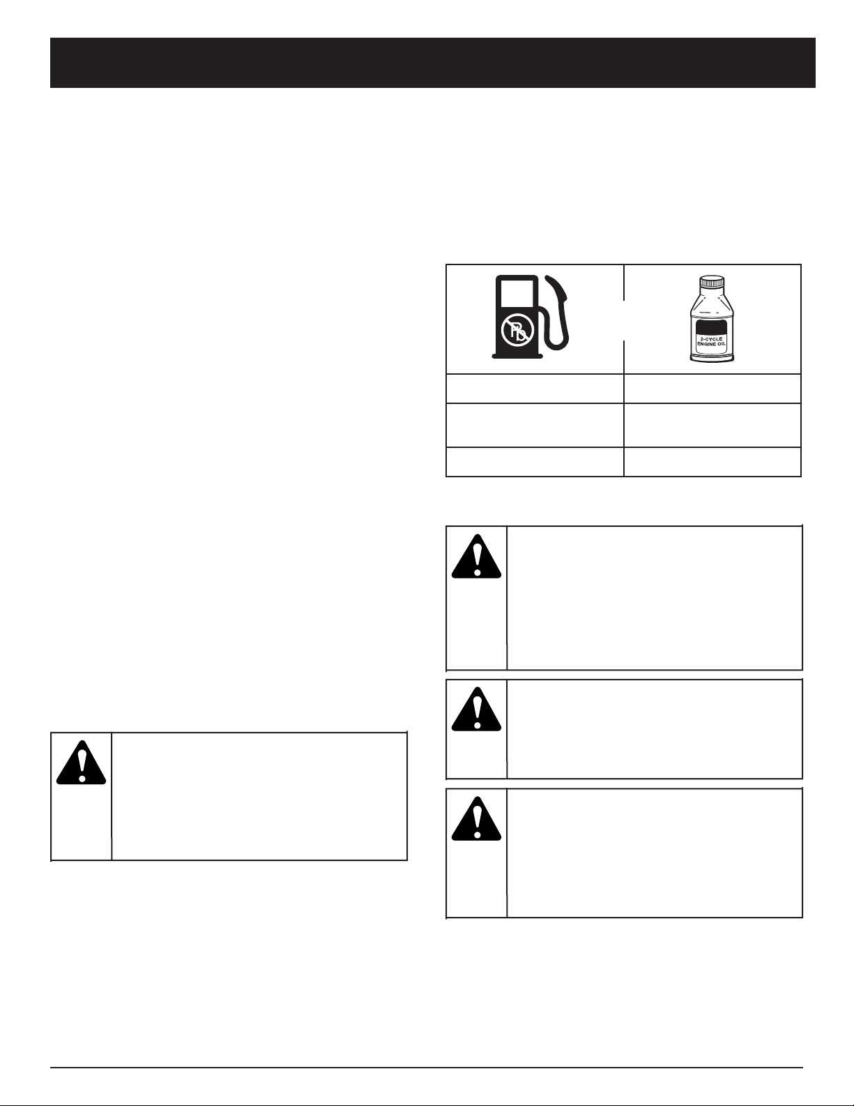
F11
INFORMATIONS SUR L'HUILE ET LE CARBURANT
MÉLANGE D'HUILE ET DE CARBURANT
En général, si l'appareil ne fonctionne pas correctement,
c'est que le carburant est vieux ou mal mélangé. Prenez
soin d'utiliser de l’essence sans plomb fraîche et propre.
Suivez à la lettre les instructions de mélange de
carburant et d'huile.
Définition des carburants mélangés
Les carburants d'aujourd'hui sont souvent un mélange
d'essence et d'oxygénés comme l'éthanol, le méthanol
ou l'éther MTBE. Un carburant mélangé à l'alcool
absorbe l'eau. Il suffit de 1 % d'eau pour séparer le
carburant et l'huile. Cela forme de l’acide pendant le
stockage. Si vous devez utiliser ce type de carburant,
servez-vous de carburant frais (moins de 60 jours).
Usage de carburants mélangés
Si vous choisissez d'utiliser ou ne pouvez éviter d'utiliser
un carburant mélangé, suivez les conseils suivants :
• Utilisez toujours un mélange de carburant frais selon le
manuel de l'utilisateur.
• Agitez toujours le mélange de carburant avant
d'alimenter l'appareil.
• Videz le réservoir et faites marcher le moteur jusqu'à
l’assécher avant d'entreposer l'appareil.
Utilisation d'additifs de carburant
La bouteille d'huile 2-temps livrée avec l’appareil
contient un additif permettant d'empêcher la corrosion
et de minimiser la formation de résidus de gomme. Nous
vous recommandons d’utiliser ce type d’huile
uniquement.
Si cela n’est pas disponible, utilisez une bonne huile
2-temps conçue pour les moteurs à 2-temps refroidis
par air en y ajoutant un additif, tel que le stabilisant de
gaz STA-BIL ou un produit équivalent Ajoutez 23 ml (0,8
oz) d'additif par 4 litres (1 gallon) de carburant selon les
instructions du récipient. N'ajoutez JAMAIS d'additifs
directement dans le réservoir de l'appareil.
REMARQUE : Éliminez le vieux mélange de carburant
conformément aux règlements fédéral, provincial
et municipal en vigueur.
Mélangez soigneusement l'huile moteur 2-temps avec
de l'essence sans plomb dans un bidon séparé. Utilisez
un rapport 40:1 d'essence/huile. Ne les mélangez pas
directement dans le réservoir de carburant. Voir le
tableau ci-dessous pour les rapports de mélange
d’essence et d’huile.
REMARQUE : 3,8 litres (1 gallon) d'essence sans
plomb mélangés avec une bouteille de 95 ml
(3.2 oz) d'huile 2-temps donnent un rapport
d’essence/huile de 40:1.
ESSENCE SANS PLOMB HUILE 2-TEMPS
3,8 LITRES
(1 GALLON US)
95 ml
(3,2 OZ)
1 LITRE 25 ml
+
RAPPORT DE MÉLANGE O - 40:1
Ajoutez
du
carburant dans un lieu propre et bien aéré
en plein air. Essuyez immédiatement tout
déversement de carburant. Évitez de mettre
le feu au carburant déversé. Ne démarrez
pas le moteur avant dissipation des
vapeurs de carburant.
AVERTISSEMENT :
Enlevez
le
bouchon du réservoir lentement pour ne
pas être blessé par les jets d'essence. Ne
faites pas marcher l'appareil sans que le
bouchon soit bien mis.
AVERTISSEMENT :
L'essence
est
extrêmement inflammable et les vapeurs qui
s'en dégagent peuvent exploser si on y met
le feu. Arrêtez toujours le moteur et laissez-le
refroidir avant de r emplir le réservoir. Ne
fumez pas en remplissant le réservoir.
Éloignez toute source d'étincelles ou de
flammes vives de la zone.
AVERTISSEMENT :
Pour
assurer
un bon fonctionnement et une fiabilité
maximale du moteur, suivez à la lettre les
instructions de mélange d'huile et de
carburant du récipient d'huile 2-temps.
L'emploi de carburant mal mélangé peut
endommager le moteur sérieusement.
MISE EN GARDE:
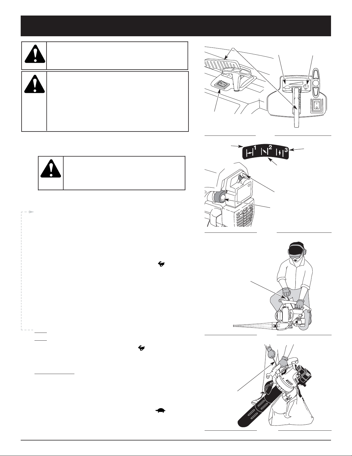
F12
INSTRUCTIONS DE DÉMARRAGE ET ARRÊT
Corde de
démarrage
DÉMARRAGE
Fig. 10
Fig. 11
INSTRUCTIONS D'ARRÊT
1. Mettez la manette des gaz en position de ralenti ( )
Laissez le moteur se refroidir au ralenti.
2. Appuyez sur la commande Marche/Arrêt Stop et maintenezla en position ARRÊT (O) jusqu'à ce que le moteur s’arrête
complètement.
1. Mélanger l’huile et l’essence et remplir le réservoir. Voir
les Instructions de mélange d’huile et de carburant.
REMARQUE : Il n’est pas nécessaire de faire démarrer la
machine. La commande On/Off (Arrêt/Marche) est
en position ON (I) en permanence (Fig. 10)
2. Pressez et relâchez la poire d’amorçage à 10 reprises,
lentement. Une certaine quantité de carburant devrait
être visible dans la poire d’amorçage et les conduites
de carburant (Fig. 11). Si vous n’apercevez pas de
carburant dans la poire, pressez et relâchez la poire
autant de fois que nécessaire jusqu’à ce que vous
aperceviez du carburant dans cette dernière.
3. Mettez le levier d'étrangleur en Position 1 (Fig. 11).
4. Mettre l’outil en position de démarrage (Fig. 12 ou 13). Mettez
la manette des gaz en position de haute vitesse ( ).
5. Tirez sèchement sur le cordon de démarrage jusqu’à 5 fois.
6. Mettez le levier d'étrangleur en Position 2.
7. Tandis que vous appuyez sur la manette des gaz, tirez
brusquement sur la corde de démarrage 1 à 3 fois pour
démarrer le moteur.
8. Maintenez la manette des gaz enfoncée et laissez le
moteur chauffer pendant 15 à 30 secondes.
9. Mettez le levier d'étrangleur en Position 3. La machine
est prête à être utilisée.
SI... Le moteur ne démarre pas, retournez à l’étape 2.
SI... Le moteur ne démarre pas après quelques tentatives,
placez l’étrangleur en position 3 et
mettez la manette
des gaz en position de haute vitesse
( ). Tirez
fermement sur le cordon de démarrage entre 3 et 8
fois. Le moteur devrait démarrer. S’il ne démarre pas,
recommencez.
SI CHAUD… Le moteur est déjà chaud, assurez-vous que
l’interrupteur Marche/Arrêt Stop est en position ON et
démarrez la machine avec le levier d’étranglement en
position 2. Après que la machine ait démarré, mettez le
levier d’étranglement en position 3.
Position de
démarrage de
l’aspirateur
Position de
démarrage
du souffleur
Fig. 12
Fig. 13
n’utiliser l’outil
qu’à l’extérieur,
dans un endroit bien aéré. Les émanations d’oxyde de
carbone dans un endroit confiné peuvent être mortelles.
AVERTISSEMENT :
éviter le démarrage
accidentel. Se tenir
en position de démarrage pour lancer le moteur (Fig. 12 et 13).
Lors du démarrage, l’opérateur et l’outil doivent être en
position d’équilibre afin d’éviter le risque de blessures graves.
D’autre part, pour le démarrage, l’outil doit toujours être posé
sur une surface propre et ferme. Les matériaux tels que le
gravier, le sable, la poussière, l’herbe, etc. peuvent être
aspirés par l’admission d’air et projetés par la sortie de l’outil.
AVERTISSEMENT :
Corde de
démarrage
Pour éviter
le risque
de blessures graves, toujours retirer le sac
d’aspirateur avant de faire l’appoint de carburant.
Le sac plein risque de s’enflammer.
AVERTISSEMENT :
Commande
Marche/Arrêt Stop
Manette des gaz
Ralenti
Haute
vitesse
Levier d'étrangleur
Poire d'amorçage
Position 1
Position 3
Position 2
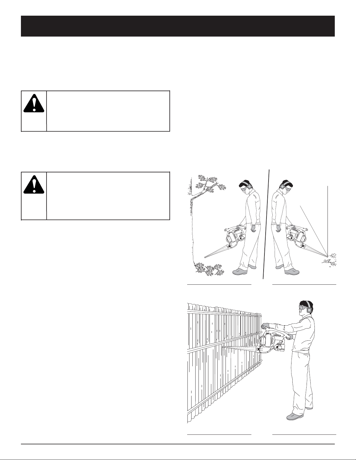
F13
MODE D'EMPLOI
TENUE DE LA SOUFFLEUSE/ASPIRATEUR
Avant d’utiliser l’outil, se tenir en position de travail et
effectuer les vérifications suivantes :
• L’utilisateur doit porter une tenue appropriée, c’est-àdire des chaussures de travail, des lunettes de
sécurité, une protection auditive, des gants, des
pantalons longs et une chemise à manches longues.
• Si l’endroit est poussiéreux, porter un masque antipoussière.
• S’assurer que l’outil est en bon état de marche.
• Vérifier que les tubes et protection sont en place et
bien assujettis.
CONSEILS PRATIQUES
• Lors du démarrage, veiller à ne pas diriger l’outil vers
des personnes ou des débris.
• S’assurer que l’outil est en bon état de marche. Vérifier
que les tubes et protection sont en place et bien
assujettis.
• Lorsque la souffleuse est utilisée à hauteur des
hanches ou dans une position inhabituelle, il est
recommandé de la tenir à deux mains.
• Utiliser une protection auditive pour éviter les risques de
perte de l’ouïe causée par un niveau de bruit élevé.
• N’utiliser l’outil qu’à des heures raisonnables, c’est-àdire pas trop tôt le matin ou tard le soir lorsque cela
peut déranger les personnes vivant aux environs. Se
conformer aux réglementations locales qui sont
habituellement de 9 à 17 heures, du lundi au samedi.
• Pour réduire le niveau sonore, utiliser le moins possible
d’outils motorisés en même temps.
• Pour réduire le niveau sonore utiliser la souffleuse au
régime minimum permettant de s’acquitter de la tâche.
• Vérifier l’équipement avant de commencer le travail, en
particulier le silencieux, l’admission d’air et les filtres à air.
• Utiliser un râteau ou un balai pour séparer les débris
avant de les souffler.
• Dans les endroits poussiéreux, humecter légèrement
l’aire de travail ou utiliser un accessoire de
pulvérisation si une source d’eau est disponible.
• Conserver l’eau en utilisant la souffleuse au lieu d’un
tuyau d’arrosage pour le nettoyage des endroits tels
que les gouttières, moustiquaires, patios, grills,
porches et jardins.
• Prendre garde aux enfants, animaux domestiques,
fenêtres ouvertes et véhicules fraîchement lavés, et
souffler les débris à l’opposé de tels obstacles.
• Utiliser la tubulure complète afin que l’embout reste
près du sol.
• Après utilisation d’une souffleuse ou d’autres outils
motorisés, Nettoyer la zone de travail. Jeter les débris
dans des poubelles.
UTILISATION DE LA SOUFFLEUSE
1 Utiliser la souffleuse pour le déblayage des arbres,
buissons, massifs de fleurs et autres endroits
difficiles à nettoyer (Fig. 14).
2. Utiliser l’outil pour le nettoyage des bâtiments et
autres applications normales (Fig. 14).
3. Utiliser la souffleuse pour le nettoyage des murs,
surplombs, palissades et moustiquaires (Fig. 15).
Fig. 14
Fig. 15
pour
éviter les
risques de blessures, toujours porter des
lunettes de sécurité lors de l’utilisation de cet
outil. Porter un masque respiratoire dans les
endroits poussiéreux.
AVERTISSEMENT :
pour
éviter les
risques de blessures à l’opérateur ou aux
personnes présentes, ainsi que des dommages
à l’outil, s’assurer que les tubes de souffleuse
ou les tubes et le sac d’aspirateur sont en place
(suivant le modèle) avant d’utiliser l’outil.
AVERTISSEMENT :
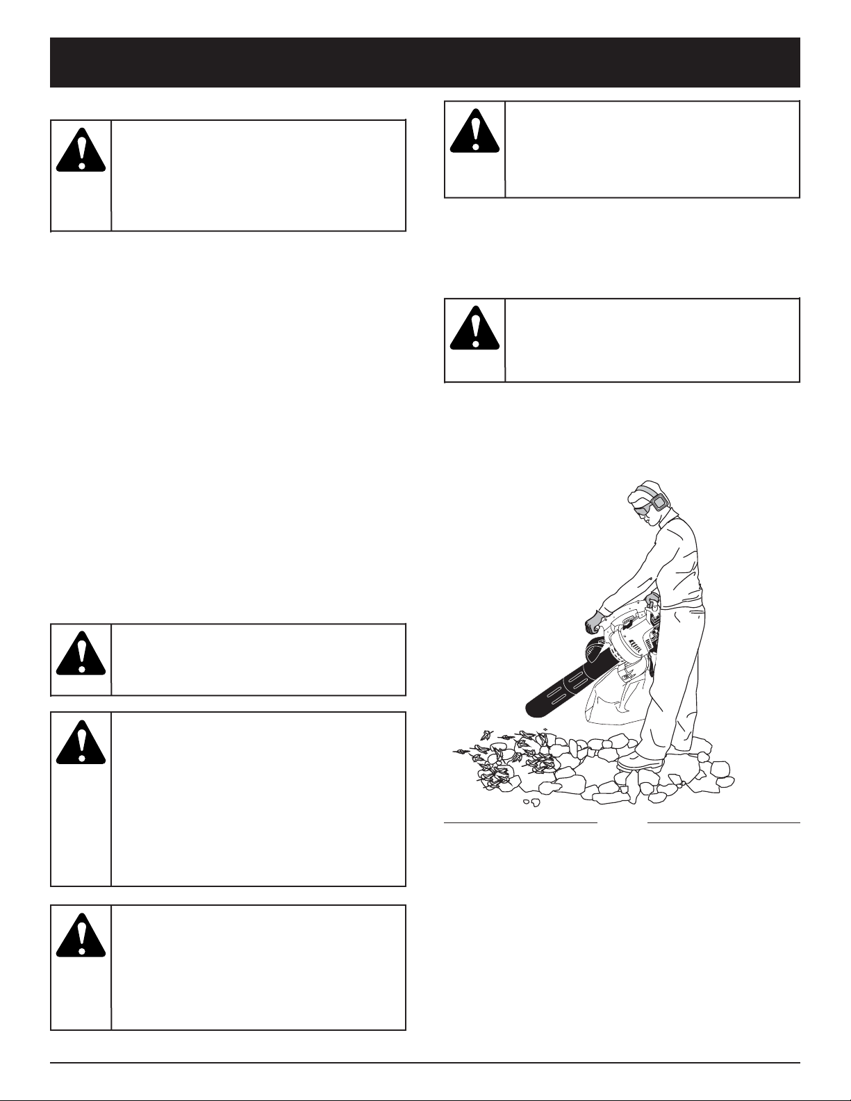
F14
MODE D'EMPLOI
Fig. 16
UTILISATION DE L’ASPIRATEUR
Vérifiez les points suivants :
• L'opérateur porte des vêtements appropriés : bottes,
lunettes de sécurité, protège-oreilles, gants, pantalons
et chemises à manches longues.
• L’opérateur porte un masque facial ou antipoussières
dans les lieux poussiéreux.
• L’appareil est en bon état de fonctionnement. Les
tubes et le sac d’aspirateur sont solidement fixés.
• Le harnais du sac d'aspirateur est installé et bien
réglé.
Utilisez l’appareil pour aspirer des débris légers, des
feuilles, du papier etc.
Tenez l’aspirateur en inclinant un peu le tube de succion,
et aspirez les débris légers d’un mouvement de balayage
(Fig. 16). Ceci permet aux débris de s’engouffrer dans le
sac de l’aspirateur. Les petites feuilles et brindilles sont
déchiquetées dans le boîtier du ventilateur pour
accroître la capacité du sac.
Lorsque le sac est plein, l’aspiration faiblit de façon
notable. Éteignez l’appareil et laissez l’hélice s’arrêter
avant d’ouvrir le sac. Ouvrez la fermeture éclair et videz
le contenu du sac avant de continuer. Voir Vider le sac
d’aspirateur.
Vider le sac d’aspirateur
1. Portez un protecteur oculaire et un masque
antipoussières, ouvrez la fermeture éclair et videz le
contenu du sac dans un sac de poubelle ou un
récipient.
2. Retournez le sac à l’envers après l’avoir vidé pour la
première fois et secouez-le vigoureusement pour
éliminer poussière et débris.
3. Fermez le sac et remettez-le en place.
Évitez les
situations
pouvant mettre le feu au sac d’aspirateur. Ne
faites pas marcher près d’une flamme vive.
N’aspirez pas les cendres chaudes des foyers
à bois ou de barbecue, des tas de broussailles,
etc. ni les cigares ou cigarettes à moins que les
cendriers soient complètement refroidis.
AVERTISSEMENT :
En tant
qu’
aspirateur, l’appareil est conçu pour ramasser
des matériaux secs comme des feuilles, de
l’herbe, des brindilles et des morceaux de
papier. Pour éviter des blessures graves,
n’essayez pas d’aspirer des débris humides
et/ou de l’eau stagnante car cela peut
endommager la souffleuse/aspirateur. Pour
éviter d'endommager sérieusement l’hélice,
n’aspirez pas de métal, de verre brisé, etc.
AVERTISSEMENT :
Afin
d'éviter
des blessures graves, n’ouvrez jamais le sac
avant d’éteindre l’appareil.
AVERTISSEMENT :
Pour
éviter des
blessures graves et ne pas endommager
l'appareil utilisé comme aspirateur, installez
toujours les tubes et le sac d’aspirateur, et
assurez-vous que la fermeture éclair du sac
est fermée.
AVERTISSEMENT :
Lorsque
les tubes
d'aspiration supérieur et inférieur sont retirés,
assurez-vous que la porte de l'aspirateur est
bien fermée avant d’utiliser l’appareil et ce
afin d’éviter de vous blesser avec l’hélice.
AVERTISSEMENT :
Pour
éviter des
blessures graves, éteignez l’appareil et laissez
l’hélice s'arrêter avant d’ouvrir la porte de
l’aspirateur ou d’installer ou de retirer le sac.
AVERTISSEMENT :

F15
ENTRETIEN ET RÉPARATIONS
REMARQUE : certaines procédures d'entretien
nécessitent des compétences ou des outils
particuliers. Si vous n'êtes pas sûr de pouvoir les
entreprendre, emmenez votre appareil dans un
atelier, chez un technicien ou un concessionnaire
agréé spécialisé dans les réparations de moteurs
d’outils mécaniques de plein air.
PROGRAMME D'ENTRETIEN
L'entretien doit respecter la fréquence indiquée dans le
tableau ci-dessous. Il doit également faire partie de
toute mise au point saisonnière.
REMARQUE: l'entretien, le remplacement ou la
réparation des dispositifs et systèmes
antipollution peuvent être effectués par tout
atelier, technicien ou concessionnaire agréé
spécialisé dans les réparations de moteurs
d’outils mécaniques de plein air.
Afin d’assurer une performance optimale du moteur, il est
conseillé d’examiner l’orifice d’échappement du moteur
après 50 heures de fonctionnement. Si vous remarquez une
perte de tours par minute, une pauvre performance ou un
manque général d’accélération, cet entretien peut s’avérer
nécessaire. Si vous pensez que le moteur a besoin de ce
type d’inspection, apportez-le pour réparation auprès d’un
atelier, technicien ou concessionnaire agréé spécialisé
dans les réparations de moteurs d’outils mécaniques de
plein air. N’essayez PAS de le faire vous-même car un
endommagement du moteur pourrait résulter de la
présence d’impuretés provenant du nettoyage de l’orifice.
FRÉQUENCE ENTRETIEN REQUIS RÉFÉRENCE
Avant démarrage Remplissez le réservoir du mélange d'essence/huile approprié Page F11
Toutes les 10 heures Nettoyez le filtre à air et lubrifiez-le de nouveau Page F15
Toutes les 25 heures
Vérifiez le pare-étincelles et nettoyez-le
Vérifiez l'état de la bougie et l'écartement des électrodes
Page F16
Page F18
Toutes les 50 heures
Examinez l’orifice d’échappement et l’écran pare-étincelles pour
détecter tout bouchage ou obstruction, afin d’assurer des
niveaux de performance maximum.
Page F16
Filtre à air
Fig. 18
Fig. 19
Protection du filtre
dans le silencieux
NETTOYAGE DU FILTRE Á AIRE
Nettoyez et relubrifiez le filtre à air à toutes les 10 heures
de fonctionnement. C'est l'un des éléments les plus
importants pour l'entretien. Tout manquement à l’entretien
du filtre à air peut entraîner une baisse de performances
ou causer des dégâts permanents à votre moteur.
1. Retirez le filtre à air/couvercle du silencieux. Voir la
section Retrait et installation du filtre à air/couvercle
du silencieux.
2. Retournez le couvercle et inspectez l'intérieur pour
repérer le filtre à air. Retirez le filtre à air de l'intérieur
du couvercle du filtre à air/silencieux (Fig. 18).
ENTRETIEN DU FILTRE À AIR
Retrait du couvercle du filtre à air/silencieux
1. Mettez le levier d'étrangleur en
Position 2
.
REMARQUE: pour enlever le couvercle du filtre à
air/silencieux, le levier d'étrangleur doit être en
Position 2
(Fig. 17).
2. Retirez les quatre (4) vis retenant le couvercle du filtre
à air/silencieux (Fig. 17). Servez-vous d'un tournevis
à mèche no. 20 Torx.
Levier
d'étrangleur
Vis
Vis
Position 2
Fig. 17
pour éviter
des blessures graves, éteignez toujours l'appareil et laissezle refroidir avant tout nettoyage ou entretien.
AVERTISSEMENT :
3. Retirez le couvercle du moteur. Ne forcez pas.
pour
éviter
tout accident, n’effectuez jamais l’entretien
ou des réparations quand l’appareil
fonctionne. Effectuez-les toujours lorsqu’il
est froid. Débranchez le câble de la bougie
pour prévenir la mise en route.
AVERTISSEMENT :
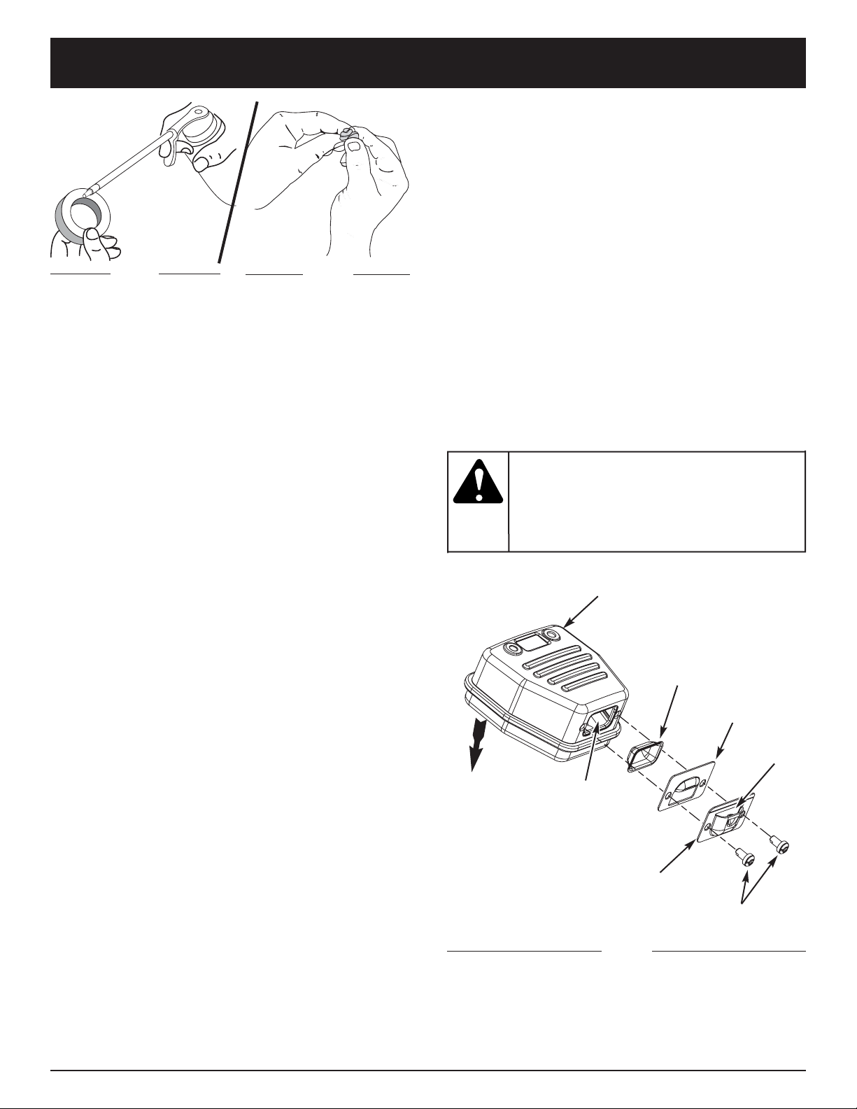
F16
ENTRETIEN ET RÉPARATIONS
Fig. 20
Fig. 21
3. Lavez le filtre dans un mélange d'eau et de détergent
(Fig. 19). Rincez le filtre abondamment. Essorez
l'excédent d'eau. Laissez sécher complètement.
4. Appliquez suffisamment d'huile propre SAE 30 pour
enduire légèrement le filtre (Fig. 20).
5. Pressez le filtre pour répartir et drainer l'excédent
d'huile (Fig. 21).
6. Remplacez le filtre à air dans le filtre à air/couvercle
du silencieux (Fig. 18).
REMARQUE : l'utilisation de l'appareil sans filtre à air et
sans ensemble filtre à air/couvercle du silencieux
ANNULERA la garantie.
Réinstallation du filtre à air/couvercle du
silencieux
1. Placez le filtre à air/couvercle du silencieux sur
l'endos du carburateur et du silencieux. Alignez les
trous à vis.
2. Insérez les quatre (4) vis dans les trous du filtre à
air/couvercle du silencieux (Fig. 17) et vissez sans
trop serrer.
ENTRETIEN DU PARE-ÉTINCELLES
REMARQUE : Les gaz de l’échappement ne peuvent
circuler que dans une direction: A L’ÉCART du
moteur. Assurez-vous que l’ensemble du silencieux
est bien assemblé afin que vous puissiez le
remonter exactement comme il était. Tout
manquement peut entraîner de graves blessures.
1. Retirez le couvercle du filtre à air/silencieux. Voir
Retrait du couvercle du filtre à air/silencieux.
2. Situez le pot d’échappement sans le retirer. Trouvez
les deux (2) vis sur la partie inférieure du pot
d’échappement (Fig. 22) Ces deux vis tiennent
l’ensemble du déflecteur d’échappement et l’écran
pare-étincelles à la partie inférieure du pot
d’échappement. Retirez les deux (2) vis en vous servant
soit d’un tournevis torx #20 ou d’un tournevis plat.
3. En vous servant du tournevis plat, écartez
soigneusement l’écran pare-étincelles du trou à
fente, en prenant soin que la partie « élevée » de
l’écran du pare-étincelle soit à l’intérieur du trou à
fente. Retirez l’écran pare-étincelles du pot
d’échappement.
si
l’ensemble
déflecteur d’échappement n’est pas
solidement assujetti, il risque de tomber et
d’endommager l’outil et de causer des
blessures graves.
AVERTISSEMENT :
4. Nettoyez l’écran du pare-étincelles à l’aide d’une
brosse métallique. Remplacez-le s’il est endommagé
ou si vous n’arrivez pas à le nettoyer complètement.
5. Réinstallez l’écran pare-étincelles en mettant la
portion « élevée » de l’écran dans le trou à fente du
port d’échappement. Assurez-vous que l’écran pareétincelle soit bien à plat contre le pot
d’échappement.
6. Placez la plaque du pare-étincelle au dessus du
pare-étincelles avec le côté « élevé » vers le haut et
l’ouverture vers le moteur (Fig. 22).
7. Placez la hotte du pare-étincelle sur la plaque du
pare-étincelle avec le côté « élevé » vers le haut et
l’ouverture tournée DU COTE OPPOSE au moteur
(Fig. 22). Assurez-vous que l’échappement soit bien
tourné DU COTE OPPOSE au moteur.
8. Revissez les deux vis que vous avez retirées à l’étape
2 et serrez-les bien.
9. Replacez le couvercle du filtre à air/silencieux.
Fig. 22
Vis
Silencieux
Moteur
Écran pare-
étincelles
Plaque pare-
étincelles
Hottre pare-
étincelles
Ouverture du
trou à fente
L’ensemble de la
hotte du pare-
étincelle comprend :
Plaque pare-étincelles
Hottre pare-étincelles
et Vis
Opening

F17
ENTRETIEN ET RÉPARATIONS
La vérification du mélange de carburant, le nettoyage du
filtre à air et le réglage de la vis de ralenti devraient
résoudre la plupart des problèmes de moteur.
Dans le cas contraire et si :
• Le moteur ne se met pas au ralenti
• Le moteur hésite ou se cale lors d'une accélération
• Le moteur perd de la puissance
faites régler le carburateur par un concessionnaire agréé.
RÉGLAGE DU CARBURATEUR
Le régime ralenti du moteur est réglable par le couvercle
du filtre à air/silencieux (Fig. 23).
REMARQUE : des réglages non soigneux peuvent
endommager sérieusement l'appareil. Les
réglages de carburateur doivent être faits par un
concessionnaire agréé.
Vérification du mélange de carburant
En général, si l'appareil ne fonctionne pas correctement,
c'est que le carburant est vieux ou mal mélangé. Videz
puis remplissez le réservoir de carburant frais et bien
mélangé avant d'effectuer des réglages. Voir la section
Informations sur l'huile et le carburant.
Nettoyage du filtre à air
L'état du filtre à air est très important pour le fonctionnement
de l'appareil. Un filtre à air sale restreint le débit d'air et
affecte le mélange de carburant/air. On confond cela
souvent avec un mauvais réglage du carburateur. Vérifiez
l'état du filtre à air avant de régler la vis de réglage de ralenti.
Voir Entretien du filtre à air.
Réglage de la vis de réglage de ralenti
Vis de réglage
de ralenti
Si le moteur ne se met toujours pas au ralenti après
vérification du mélange de carburant et nettoyage du
filtre à air, réglez la vis de ralenti comme suit :
1. Démarrez le moteur et laissez-le tourner à haut
régime pendant une minute pour se réchauffer.
L’appareil
doit être
en marche pendant le réglage du ralenti.
Portez des vêtements protecteurs et
respectez toutes les consignes de sécurité
pour éviter des blessures graves.
De plus, posez l’appareil sur une surface
propre et dure uniquement lors du dém
arrage ou d’un réglage. Les débris tel que
gravier, sable, poussière, herbe, etc. peuvent
être aspirés par la prise d'air et rejetés par
l’ouverture de décharge, endommageant ainsi
l’appareil ou des biens matériels ou causant
des blessures graves aux personnes.
AVERTISSEMENT :
Fig. 23
2. Relâchez le levier d'accélérateur et laissez le moteur
au ralenti. Si le moteur s'arrête, insérez un petit
tournevis à embout cruciforme ou à tête plate dans le
trou du couvercle du filtre à air/silencieux (Fig. 23).
Vissez la vis de réglage du ralenti de 1/8 de tour à la
fois (selon le besoin) jusqu'à ce que le moteur se
mette bien au ralenti
3. Si le ralenti semble trop rapide, dévissez la vis de
réglage du ralenti de 1/8 de tour à la fois (selon le
besoin) pour réduire la vitesse de ralenti.
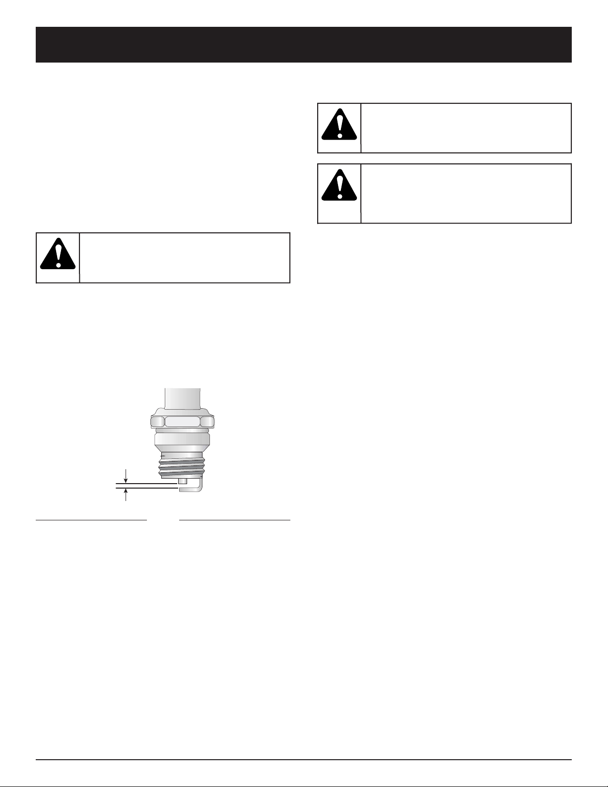
F18
DÉGAGEMENT D’UN(E) TUBE/ HÉLICE
BLOQUÉ(E)
1. Appuyez sur la commande Marche/Arrêt Stop et
maintenez-la en position ARRÊT (O) jusqu'à ce que
le moteur s’arrête complètement (Fig. 10).
2. Déconnectez le câble de bougie pour empêcher
l'appareil de démarrer.
3. Retirez le tube de la soufflante/aspirateur et le sac de
l'aspirateur.
4. Enlevez soigneusement tout matériau bloquant le
tube ou l’hélice. Inspectez les lames pour vous
assurer qu’elles ne sont pas endommagées. Tournez
les lames de l’hélice à la main pour vous assurer
qu’elles ne sont plus bloquées.
5. Réinstallez le sac d’aspirateur et le tube de
souffleuse/aspirateur.
6. Rebranchez le câble de la bougie.
REMPLACEMENT DE LA BOUGIE
Utilisez une bougie #610311 (ou un Champion RDJ7Y).
L'écartement correct est de 0,5 mm (0,020 po).
Retirez la bougie après 25 heures de fonctionnement et
vérifiez son état.
1. Arrêtez le moteur et laissez-le refroidir. Saisissez
fermement le câble de la bougie et retirez le
capuchon de celle-ci.
2. Nettoyez toute saleté de la bougie. Retirez la bougie de
la culasse en tournant la douille de 5/8 po à gauche.
3. Remplacez toute bougie fendillée, encrassée ou sale.
Réglez l'écartement à 0,5 mm (0,020 po) à l'aide
d'une jauge d'épaisseur (Fig. 24).
4. Installez la bougie avec un écartement correct dans
la culasse en tournant la douille de 5/8 po à droite
jusqu'à la bien visser.
Si vous utilisez une clé dynamométrique vissez avec les
valeurs de couple suivantes :
110-120 po•lb (12,3-13,5 N•m).
Évitez de trop serrer.
0,5 mm
(0,020 po)
Fig. 24
évitez de
sabler ,
gratter ou nettoyer les électrodes car de la saleté
dans le moteur pourrait endommager le cylindre.
MISE EN GARDE:
ENTRETIEN ET RÉPARATIONS
Pour
éviter des
blessures graves, éteignez l'appareil avant
tout nettoyage ou entretien.
AVERTISSEMENT :
Pour
éviter des
blessures graves, portez toujours des gants
pour vous protéger des lame de l’hélice ou
d’autres objets tranchants.
AVERTISSEMENT :

F19
NETTOYAGE
Nettoyer l’extérieur de l’outil à l’aide d’une petite brosse.
Ne pas utiliser de détergents puissants. Les produits
ménagers contenant des huiles aromatiques tel que le
pin et le citron et les solvants tel que le kérosène peuvent
endommager le boîtier ou la poignée en plastique.
Essuyer toute trace d’humidité à l’aide d’un chiffon doux.
NETTOYAGE DU SAC D’ASPIRATEUR
1. Videz le sac après chaque utilisation pour éviter toute
détérioration et ne pas restreindre le débit d'air, ce
qui affaiblirait les performances de l’aspirateur.
2. Portez un protecteur oculaire et un masque
antipoussières pour nettoyer le sac. Retournez le sac
à l’envers après l’avoir vidé pour la première fois et
secouez-le vigoureusement pour éliminer poussière
et débris.
3. Lavez le sac une fois par an ou plus selon le besoin :
a. Retirez le sac d’aspirateur.
b. Retournez-le à l’envers.
c. Suspendez-le.
d. Lavez-le abondamment avec un tuyau.
e. Suspendez-le et laissez sécher.
f. Retournez le sac à l’endroit et remettez-le en place.
REMISAGE
• Ne jamais remiser l’outil plein de carburant dans un
lieu où les vapeurs peuvent atteindre une flamme vive
ou des étincelles.
• Laisser le moteur refroidir avant le remisage.
• Remiser l’outil dans un lieu verrouillé pour éviter toute
utilisation non autorisée ou éviter des dommages.
• Remiser l’outil dans un lieu sec et bien aéré.
• Remiser l’outil hors de portée des enfants.
ENTRETIEN ET RÉPARATIONS
REMSISAGE À LONG TERME
Si l’outil doit être remisé pour une période prolongée,
procéder comme suit :
1. Vider tout le carburant du réservoir dans un récipient
contenant le même mélange 2-temps. Ne pas utiliser
de carburant entreposé pendant plus de 60 jours.
Éliminer le vieux mélange de carburant
conformément aux réglementations
gouvernementales et locales en vigueur.
2. Démarrer le moteur, puis le laisser tourner jusqu’à ce
qu’il cale afin de brûler tout lecarburant.
3. Laisser le moteur refroidir. Retirer la bougie et verser
environ 30 ml (1 oz) d’huile moteur 2-temps de bonne
qualité dans le cylindre. Tirer lentement sur la corde
de démarrage pour bien répartir l’huile. Remettre la
bougie en place.
REMARQUE : retirer la bougie et vider toute l’huile du
cylindre avant de démarrer l’outil après une
période de remisage.
4. Nettoyer soigneusement l’outil et vérifier qu’il n’y a
pas de pièces desserrées ou endommagées. Réparer
ou remplacer les pièces endommagées, puis serrer
les vis, écrous et boulons selon le besoin. L’outil est
alors prêt pour le remisage.
TRANSPORT
• Laisser le moteur refroidir avant le transport.
•Bien arrimer l’outil pour le transport.
• Vider tout le carburant de l’outil.
• Serrer le bouchon du réservoir avant le transport.
pour
éviter des
blessures graves, éteignez toujours
l'appareil et laissez-le refroidir avant tout
nettoyage ou entretien.
AVERTISSEMENT :

F20
DÉPANNAGE
CAUSE SOLUTION
Carburant vieux ou mal mélangé Vider le réservoir/ajouter du carburant frais
Filtre à air colmaté Le remplacer ou le nettoyer
Mauvais réglage du carburateur Le faire régler par un concessionnaire agréé
Bougie encrassée La remplacer ou la nettoyer
Pare-étincelles colmaté Nettoyez ou remplacez le pare-étincelles
CAUSE SOLUTION
Étrangleur en position incorrecte Voir les instructions de démarrage/arrêt
Réservoir de carburant vide Le remplir de carburant bien mélangé
La poire d’amorçage n’a pas été enfonçée un nombre de Le remplir de carburant bien mélangé. L’enfoncer
fois suffisant complètement et lentement 10 fois
Moteur noyé Démarrez la machine avec l’étrangleur en position 3
Carburant vieux ou mal mélangé Vider le réservoir/ajouter du carburant frais
Bougie encrassée La remplacer ou la nettoyer
Pare-étincelles colmaté Nettoyez ou remplacez le pare-étincelles
LE MOTEUR NE DÉMARRE PAS
LE MOTEUR NE GARDE PAS LE RALENTI
LE MOTEUR N’ACCÉLÈRE PAS
LE MOTEUR MANQUE DE PUISSANCE OU CALE
CAUSE SOLUTION
Filtre à air colmaté Le remplacer ou le nettoyer
Carburant vieux ou mal mélangé Vider le réservoir/ajouter du carburant frais
Mauvais réglage du carburateur Ajuster selon les instructions
CAUSE SOLUTION
Carburant vieux ou mal mélangé Vider le réservoir/ajouter du carburant frais
Mauvais réglage du carburateur Le faire régler par un concessionnaire agréé
Filtre à air sale Le remplacer ou le nettoyer
Pare-étincelles colmaté Nettoyez ou remplacez le pare-étincelles
Pour toute assistance, contacter le concessionnaire agréé.
CAUSE SOLUTION
Sac plein Videz le sac, voir Vider le sac d’aspirateur
Tube bouché Dégagez le tube, voir Dégagement d'un(e)
tube/hélice bloqué(e)
Hélice bouchée Dégagez le tube, voir Dégagement d'un(e)
tube/hélice bloqué(e
Hélice endommagée Confiez l’appareil à un concessionnaire agréé
L’APPAREIL NE SOUFFLE/N’ASPIRE PAS

F21
CARACTÉRISTIQUES
Type de moteur............................................................................................................................. Refroidi par air, 2-temps
Cylindrée........................................................................................................................................................ 31 cc (1,9 po3)
Régime de fonctionnement (Aspirateur)......................................................................................................... 6.800+ tr/min
Régime de fonctionnement (Souffleuse) ......................................................................................................... 7.200+ tr/min
Régime ralenti ........................................................................................................................................ 3.200-4.400 tr/min
Type d'allumage................................................................................................................................................ Électronique
Commande Marche/Arrêt Stop............................................................................................................ Interrupteur berceau
Écartement de la bougie......................................................................................................................... 0,5 mm (0,020 po)
Lubrification ................................................................................................................................... Mélange carburant/huile
Rapport carburant/huile................................................................................................................................................ 40:1
Carburateur.............................................................................................................................. Membrane, toutes positions
Démarreur.................................................................................................................................. Rembobinage automatique
Silencieux....................................................................................................................................... Chicane avec protection
Capacité du réservoir de carburant............................................................................................................... 384 ml (13 oz)
Manette des gaz.......................................................................................................................... Détente à portée du doigt
Vélocité de la souffleuse............................................................................................................... 322 km/h (200 m/h) max.
Sortie d’air de la souffleuse................................................................................................. 12,1 m3/min (425 pi
3
/min) max.
Rapport de paillage............................................................................................................................................... 10:1 max.
Capacité du sac d'aspirateur............................................................................................................. 52,8 l (1,5 boisseaux)
Poids à vide (sans carburant, avec tube de souffleuse)................................................................................ 5,2 kg (11,4 lb)
MOTEUR*
SOUFFLEUSE/ASPIRATEUR*
*Toutes les spécifications contenues dans ce manuel tiennent compte des dernières informations techniques disponibles au
moment de mettre sous presse. Nous nous réservons le droit d'y apporter des modifications à tout moment, sans préavis.

F22
REMARQUES

F23
Garantie portant sur les normes antipollution de l'EPA et la California
Vos droits et obligations en vertu de cette garantie
Le California Air Resource Board, la Environmental Protection Agency et MTD LLC (MTD) ont le plaisir de présenter la
garantie du dispositif antipollution des petits moteurs à usage tout-terrain datant de 2000 et au-delà. Les nouveaux
petits moteurs à usage tout-terrain doivent être conçus, construits et équipés pour être conformes aux strictes normes
anti-smog. MTD doit garantir le système de contrôle des émissions de votre petit moteur à usage tout-terrain pendant
les périodes de temps indiquées ci-dessous à condition que le moteur n'ait pas souffert d'abus, de négligence ou fait
l'objet d'un mauvais entretien.
Votre dispositif antipollution peut inclure des pièces diverses tel que le carburateur ou un système d'injection, le
dispositif d'allumage et un convertisseur catalytique. Il pourrait aussi inclure des tuyaux, courroies, connecteurs et
autres ensembles de pièces relatives aux émissions.
Advenant une situation couverte par la garantie, MTD réparera votre petit moteur à usage tout-terrain sans frais aucun y
compris le diagnostic, les pièces et la main d'œuvre.
Les moteurs à usage tout-terrain datant de 2000 et plus sont garantis pendant deux ans. Si une pièce de votre moteur
relative aux émissions devenait défectueuse, MTD la réparera ou la remplacera.
Responsabilités du propriétaire en vertu de cette garantie
• En tant que propriétaire d'un petit moteur à usage tout-terrain, vous êtes responsable des entretiens requis indiqués
dans votre manuel de l'utilisateur. MTD recommande que vous conserviez tous les reçus d'entretien de votre petit
moteur à usage tout-terrain. MTD ne peut toutefois réfuter votre garantie juste parce que vous n'avez pas les reçus ou si
vous ne veillez pas à ce que les travaux d'entretien prévus soient effectués.
• En tant que propriétaire d'un petit moteur à usage tout-terrain, sachez que MTD peut refuser de vous couvrir sous
garantie si votre moteur ou si une pièce sont défaillants pour cause d'abus, de négligence, d'entretien incorrect ou de
modifications non autorisées.
• Il vous incombe de présenter votre petit moteur à usage tout-terrain à un centre de service agréé MTD dès que le
problème fait son apparition. Les réparations sous garantie doivent être achevées dans une durée de temps raisonnable
ne dépassant en aucun cas 30 jours.
Si vous avez des questions au sujet de vos droits et responsabilités en vertu de cette garantie, appelez le 1-800-345-8746.
Garantie du fabricant
• La période de garantie commence à la date où le moteur ou l'équipement est livré à l'acheteur au détail.
• Le fabricant garantit au propriétaire initial et à chaque acheteur subséquent que le moteur est libre de défauts de matériaux et
de vices de fabrication pouvant provoquer la défaillance d'une pièce garantie pendant une période de deux ans
.
• Toute réparation ou remplacement d'une pièce garantie devra être effectué sans aucun frais au compte du propriétaire par un
centre de service MTD agréé. Pour connaître le centre le plus proche de vous, veuillez contact MTD à : 1-800-345-8746.
• Toute pièce garantie dont le remplacement n'est pas prévu dans le cadre des entretiens requis, ou dont uniquement
une inspection normale est prévue selon le principe de "réparation ou remplacement au besoin", est garantie pendant la
période de garantie. Toute pièce garantie dont le remplacement est prévu dans le cadre des entretiens requis sera
garantie pendant la période de temps allant jusqu'à la date du premier remplacement prévu pour cette pièce.
• Le propriétaire ne subira pas de frais relatifs à un travail de diagnostic qui conclut que la pièce garantie est
défectueuse si le travail de diagnostic a été effectué chez un centre de service MTD agréé.
• Le fabricant est responsable de tous les dommages occasionnés aux autres composants du moteur par la défaillance
d'une pièce encore sous garantie.
• Les défaillances causées par l'abus, la négligence ou un mauvais entretien ne sont pas couvertes par cette garantie.
• L'utilisation d'un ajout ou de pièces modifiées peut justifier le refus d'une réclamation au titre de la garantie. Le
fabricant n'est pas responsable des défaillances des pièces garanties découlant de l'utilisation d'ajouts ou de pièces
modifiées.
• Pour déposer une réclamation, adressez-vous au centre de service MTD agréé le plus proche. Les services ou
réparations sous garantie sont offerts par tous les centres de service MTD agréés.
• Toutes les pièces de rechange approuvées par le fabricant peuvent être utilisées dans le cadre d'un entretien ou d'une
réparation sous garantie de pièces relatives au dispositif antipollution et sont fournies sans frais. Toute pièce de
rechange équivalente en termes de performances ou de durabilité peut être utilisée lors d'un entretien ou d'une
réparation hors garantie et ne diminue pas les obligations qui incombent au fabricant en vertu de la garantie.
• Les composants suivants sont inclus dans la garantie relative au système antipollution du moteur : filtre à air,
carburateur, poire d'amorçage, conduites de carburant, alimentation d'arrivée, filtre à carburant, module d'allumage,
bougie et silencieux.

GARANTIE LIMITÉE DU FABRICANT POUR:
Aucune garantie implicite, y compris toute garantie de
valeur marchande ou d’adaptation à une fin particulière, ne
s’applique après la période applicable de garantie
expresse écrite ci-dessus concernant les pièces qui sont
identifiées. Aucune autre garantie ou caution expresse,
écrite ou orale, à l’exception de celle mentionnée cidessus, accordée par toute personne ou entité, y compris
tout distributeur ou détaillant, concernant tout produit
n’engagera la responsabilité de MTD. Pendant la période
destates garantie, le remède exclusif est la réparation ou le
remplacement du produit dans les conditions énoncées cidessus. (Certains états ne permettent pas la limitation de la
garantie implicite, il est donc possible que la limitation cidessus ne s’applique pas à vous.)
Les clauses énoncées dans la présente Garantie
constituent le recours unique et exclusif inhérent aux
ventes. MTD ne sera en aucun cas tenue pour
responsable de tout dommage indirect ou consécutif ou
de dommages comprenant, entre autres mais pas
seulement, les dépenses encourues du fait du recours à
des services de remplacement ou de substitution pour
l’entretien des pelouses, le transport ou des frais
connexes, ou les frais entraînés par une location
destinée à remplacer provisoirement un produit sous
garantie. (Certains états ne permettent pas la limitation de la
garantie implicite, il est donc possible que la limitation cidessus ne s’applique pas à vous.)
Aucun recouvrement, quel qu’il soit, ne sera d’un montant
supérieur au prix du produit vendu. Toute modification des
dispositifs de sécurité du produit annulera la présente
Garantie. Vous assumez tout risque et toute responsabilité
résultant de la perte, de l’endommagement ou du préjudice
que vous et votre propriété et/ou d’autres et leur
propriété pourront encourir du fait de l’utilisation normale, de
la mauvaise utilisation ou de l’empêchement d’utiliser le
produit.
La présente garantie limitée n’est accordée qu’à l’acheteur
initial, au preneur initial ou à la personne à laquelle le produit
a été offert.
Le Droit des États vis à vis de la présente garantie : la
présente garantie vous confère certains droits juridiques, et
vous pouvez bénéficier d’autres droits, lesquels varient
d’une juridiction à l’autre.
Pour obtenir l’adresse du distributeur agréé le plus proche,
composer le : 1-800-345-8746 aux États-Unis ou le
1-800-668-1238 au Canada.
MTD LLC
P.O. Box 361131
Cleveland, OH 44136-0019
La garantie limitée énoncée ci-après est accordée par MTD
LLC (« MTD ») et concerne les marchandises neuves achetées
et utilisées aux États-Unis, ainsi que dans leurs possessions et
territoires.
MTD garantit ce produit contre tout vice de matière ou de façon
pendant une période de deux (2) ans à compter de la date
d’achat initiale et elle se réserve le choix de réparer ou de
remplacer, à titre gratuit, toute pièce présentant un vice de
matière ou de façon. Cette garantie limitée nes’ appliquera que
dans la mesure où le produit aura été utilisé et entretenu
conformément au Guide de l’utilisateur fourni avec le produit et
n’aura pas fait l’objet d’un usage inadéquat, abusif, commercial
ou négligent, d’un accident, d’un entretien inadéquat, d’une
modification, de vandalisme, d’un vol, d’un incendie, de dégâts
d’eau ou d’un endommagement résultant d’un autre péril ou
d’un désastre naturel. Les dommages résultats de l’installation
ou de l’utilisation de tout accessoire ou équipement non
approuvé par MTD pour une utilisation avec le(s) produit(s)
couvert(s) par le présent guide annuleront la garantie et ce qui
concerne les dommages qui en résulteraient éventuellement.La
présente garantie est limitée à quatre-vingt-dix (90) jours à
compter de la date d’achat au détail initiale pour tout produit
MTD utilisé à des fins locatives ou commerciales, ou toute
utilisation produisant des revenus.
POUR L’ENTRETIEN-DÉPANNAGE : l’Entretien-dépannage
au titre de la garantie est disponible, SUR PRÉSENTATION
DE PREUVE D’ACHAT, AUPRÈS DU DISTRIBUTEUR AGRÉÉ
LOCAL. Pour obtenir le nom du distributeur agréé local,
consulter les Pages Jaunes ou se mettre en rapport avec le
Service après-vente de MTD LLC. en appelant le 1-800-3458746 ou en écrivant au P.O. Box 361131, Cleveland OH
44136-0019 ou en appelant le 1-800-668-1238 au Canada.
Aucun produit retourné à l’usine sans permission écrite
préalable du service après-vente de MTD LLC ne sera
accepté.
La garantie limitée n’offre aucune couverture dans les
cas suivants :
A. Mises au point – Bougies, réglages de carburateur,
filtres.
B. Articles d’usure – Bouton de butée, bobines extérieures, fil
de coupe, bobines intérieures, poulie de démarrage,
cordes de démarrage, courroies d’entraînement.
C. MTD n’accorde aucune garantie pour les produits
vendus ou exportés des États-Unis, de leurs
possessions et territoires, exception faite en ce qui
concerne les produits vendus par l’intermédiaire de ses
canaux agréés de distribution à l’exportation.
MTD se réserve la droit de modifier ou d’améliorer la
conception de tout produit MTD sans assumer l’obligation
de modifier tout produit d’une fabrication plus ancienne.

Manuel del Dueño/Operador
YM320BV
Soplador / Aspirador
Triturador de 2 Ciclos
P/N 769-01400 (1/05)
IMPRESO EN LOS EE.UU
ESTE MANUAL ES IMPORTANTE NO LO DESECHE

E2
INTRODUCCION
Copie el número del modelo/
pieza del fabricante aquí:
Copie el número
de serie aquí:
MUCHAS GRACIAS
Gracias por haber adquirido este gran producto. Esta
moderna herramienta motriz de exteriores está diseñada
para brindarle muchas horas de servicio útil. Usted
comprobará que es un artefacto que le ahorrará mucho
trabajo. Este manual del operador le brinda instrucciones
de operación de fácil comprensión. Lea todo el manual y
siga todas las instrucciones para mantener su nueva
herramienta motriz de exteriores en las mejores
condiciones de funcionamiento.
REFERENCIAS, ILUSTRACIONES Y
ESPECIFICACIONES DEL PRODUCTO
Toda la información, las ilustraciones y las especificaciones
contenidas en este manual se basan en la información
más reciente disponible en el momento de impresión del
manual. Nos reservamos el derecho de hacer cambios
en cualquier momento sin aviso previo.
Copyright© 2005 MTD SOUTHWEST INC. Todos los
derechos reservados.
INFORMACION DEL SERVICIO
El servicio de esta unidad, ya sea durante o después del
período cubierto por la garantía, debe ser realizado
solamente por un proveedor de servicios autorizado y
aprobado. Llame 1-800-345-8746 en EE.UU. o al 1-800-
668-1238 en Canada para obtener una lista de
distribuidores de servicio localizados cerca de usted.
Para obtener más detalles sobre su unidad, visite
nuestro sitio en www.Yardman.com.
NO REGRESE SU UNIDAD AL VENDEDOR. PARA
SOLICITAR SERVICIO POR LA GARANTIA, DEBERA
PRESENTAR PRUEBA DE SU COMPRA.
Antes de que empiece a ensamblar su nuevo equipo, por
favor ubique la placa que contiene el modelo de la
unidad y escriba esa información en el espacio en blanco
aquí debajo. Aquí debajo se explica la muestra de una
placa del modelo.
Antes de arrancar u operar este equipo, asegúrese de
leer y comprender bien este manual.
ESTE PRODUCTO ESTA CUBIERTO POR UNA O MAS
PATENTES DE EE.UU., OTRAS PATENTES EN
TRAMITE.
INDICE DE CONTENIDOS
Llamadas a apoyo al cliente . . . . . . . . . . . . . . . . . . .2
Normas para una operación segura . . . . . . . . . . . . .3
Conozca su unidad . . . . . . . . . . . . . . . . . . . . . . . . .7
Instrucciones de ensamble . . . . . . . . . . . . . . . . . . .8
Información del aceite y del combustible . . . . . . . .11
Instrucciones de arranque y apagado . . . . . . . . . .12
Instrucciones de operación . . . . . . . . . . . . . . . . . .13
Instrucciones de mantenimiento y reparación . . . .15
Accesorios y piezas de repuesto . . . . . . . . . . . . . .19
Limpieza y almacenamiento . . . . . . . . . . . . . . . . . .19
Cuadro de solución de problemas . . . . . . . . . . . . .20
Especificaciones . . . . . . . . . . . . . . . . . . . . . . . . . . .21
Garantía . . . . . . . . . . . . . . . . . . . . . . . . . . . . . . . . .26
Lista de Piezas . . . . . . . . . . . . . . . . . .Contraportada
PARACHISPAS
NOTA: Para los usuarios en tierras forestales de los
EE.UU. y en los estados de California, Maine, Oregon
y Washington. Todos los terrenos forestales de los
EE.UU. y el estado de California (Códigos de Recursos
Públicos 4442 y 4443), Oregon y Washington, requieren
por decreto, que ciertos motores de combustión interna
que se hagan funcionar en zonas boscosas y/o zonas
cubiertas por pastizales, estén equipados con un
parachispas, que sean mantenidos en buen estado de
funcionamiento o que el motor sea construido, esté
equipado y sea mantenido para evitar incendios.
Consulte los reglamentos pertinentes a esos requisitos
con las autoridades estatales o locales. El incumplimiento
de esos requisitos puede responsabilizarle o someterle a
la imposición de una multa. Esta unidad fue equipada
en la fábrica con un parachispas. Si requiere
sustitución, hay una Pantalla Parachispas disponible,
Pieza #753-04689 al contactar el departamento de
servicio.
ADVERTENCIA
LAS EMISIONES DEL MOTOR DE ESTE
PRODUCTO CONTIENEN SUBSTANCIAS
QUIMICAS QUE EL ESTADO DE
CALIFORNIA CONOCE COMO CAUSANTES
DECANCER, DEFECTOS DE NACIMIENTO
U OTROS DAÑOS REPRODUCTIVOS.
Número de la
pieza del fabricante
Número de serie
Número del
modelo
PROPOSICIÓN 65 DE CALIFORNIA
S/N :
MODEL :
ITEM :

E3
LEA TODAS LAS INSTRUCCIONES
ANTES DE LA OPERACIÓN
• Lea todas las instrucciones con cuidado. Conozca
bien los controles y el uso correcto de la unidad.
• No opere esta unidad si está cansado, enfermo, o bajo
los efectos del alcohol, drogas o medicamentos.
• Los niños y los adolescentes menores de 15 años no
deben operar las unidades, excepto por los
adolescentes guiados por un adulto.
• Se debe instalar adecuadamente todos los
protectores y accesorios de seguridad antes de hacer
funcionar la unidad.
• Inspeccione la unidad antes de utilizarla. Cambie las
partes dañadas. Verifique si existen fugas de
combustible. Asegúrese de que los sujetadores estén
bien colocados y asegurados. Cambie las piezas que
estén quebrabas, astilladas o dañadas de alguna
manera. No funcione la unidad cuando ésta tenga
piezas sueltas o dañadas.
• Inspeccione cuidadosamente el área antes de poner
en marcha la unidad. Retire todos los desechos y
objetos duros o filosos tales como vidrio, alambre, etc.
• Aleje a todos los niños, espectadores y animales
domésticos. Mantenga todos los niños, espectadores
y animales domésticos a un radio de por lo menos
15 m (50 pies) ; aún así puede existir un riesgo de
objetos despedidos contra los espectadores. Los
espectadores deben usar protección para sus ojos. Si
alguien se le acerca, pare la unidad inmediatamente.
ADVERTENCIAS DE SEGURIDAD PARA
UNIDADES A GASOLINAS
• Guarde el combustible en envases que hayan sido
diseñados y aprobados para el almacenamiento de
dichos materiales.
• Evite crear una fuente de encendido por combustible
derramado. No arranque el motor hasta que se hayan
disipado los vapores del combustible.
• Apague siempre el motor y espere que se enfríe. No
retire nunca la tapa del tanque de combustible ni cargue
combustible mientras el motor esté caliente. Nunca
opere la unidad sin la tapa del combustible colocada
firmemente en su lugar. Afloje la tapa del combustible
lentamente para disipar la presión del tanque.
.•Agregue el combustible en una zona limpia, bien
ventilada y al aire libre, donde no haya chispas ni
llamas. Quite lentamente la tapa del combustible sólo
después de apagar el motor. No fume mientras carga
o mezcla el combustible. Limpie de inmediato todo el
combustible que se haya derramado. Seque siempre
la unidad con un trapo antes de usarla.
•Aleje la unidad a por lo menos 9,1 m (30 pies) del lugar
de carga de combustible antes de arrancar el motor. No
fume. Mantenga las chispas y las llamas abiertas lejos
del área mientras carga el combustible u opera la unidad.
NORMAS PARA UNA OPERACION SEGURA
SIMBOLO SIGNIFICADO
Los símbolos de seguridad se utilizan para llamar su
atención sobre posibles peligros. Los símbolos de
seguridad y sus explicaciones merecen toda su atención
y comprensión. Los símbolos de seguridad no eliminan
ningún peligro por sí mismos. Las instrucciones o
advertencias que ofrecen no substituyen las medidas
adecuadas de prevención de accidentes.
SIMBOLO SIGNIFICADO
• IMPORTANTE INFORMACION DE SEGURIDAD •
El no
seguir una
advertencia de seguridad puede conducir a
que usted u otras personas sufran lesiones.
Siga siempre las precauciones de seguridad
para reducir el riesgo de incendio, descarga
eléctrica y lesiones personales.
ADVERTENCIA:
El no obedecer una
advertencia de
seguridad puede conducir a que usted u
otras personas sufran graves lesiones. Siga
siempre las precauciones de seguridad
para reducir el riesgo de incendio, descarga
eléctrica y lesiones personales.
PELIGRO:
El no seguir
una
advertencia de seguridad puede conducir a
daño patrimonial o a que usted u otras
personas sufran lesiones personales. Siga
siempre las precauciones de seguridad
para reducir el riesgo de incendio, descarga
eléctrica y lesiones personales.
PRECAUCION:
Indica peligro, advertencia o precaución.
Debe prestar atención para evitar sufrir
graves lesiones personales. Puede ser
utilizado junto con otros símbolos o figuras.
ALERT A DE SEGURIDAD
:
NOTA: Le ofrece información o instrucciones que son
esenciales para la operación o mantenimiento
del equipo.
La gasolina
es muy
inflamable y sus gases pueden explotar si se
encienden. Tome las siguientes precauciones:
ADVERTENCIA:
Lea el manual del operador y siga todas las
advertencias e instrucciones de seguridad. De no
hacerlo, el operador y/o los espectadores pueden
sufrir graves lesiones.
SI TIENE PREGUNTAS, LLAME AL 1-800-345-8746
EN EE.UU. O AL 1-800-668-1238 en CANADA

E4
NORMAS PARA UNA OPERACIÓN SEGURA
DURANTE LA OPERACIÓN
• No arranque ni opere la unidad en un cuarto o edificio
cerrado. Los gases de escape de monóxido de
carbono pueden ser letales en un área cerrada. Opere
esta unidad sólo en un área exterior bien ventilada.
• Para reducir el riesgo de lesiones asociadas con los
objetos lanzados, utilice gafas de protección que
tengan una marca de clasificación normativa ANSI Z87.
• Nunca haga funcionar la unidad sin que ésta tenga
conectado el equipo apropiado. Cuando use esta
unidad, instale siempre los tubos de la sopladora /
aspiradora y la bolsa de recolección, dependiendo del
modelo. Asegurese de cerrar completamente la bolsa
de recolección.
• Para reducir el riesgo de pérdida auditiva asociada con
los niveles de sonido, use siempre protección para las
orejas / oídos cuado haga funcionar esta unidad.
• Use pantalón largos y gruesos, botas y guantes. No
use pantalones cortos, sandalias ni ande descalzo.
• Para evitar el choque de electricidad estática, no se
ponga guantes de caucho o guantes aislados mientras
haga funcionar esta unidad.
• Para reducir el riesgo de lesión asociada con objetos que
sean atraídos hacia las piezas que giran, no use ropa
suelta, joyas, bufandas ni cosas parecidas. Asegurese el
cabello por encima del nivel de los hombros.
• Úse una mascara para la cara o contra el polvo si el
trabajo es polvoriento. Se recomiendan las camisas de
manga larga.
• Use la unidad únicamente con la luz del día o con
buena luz artificial.
• Mantenga las superficies exteriores libres de aceite y
combustible.
• Evite arrancar la unidad accidentalmente. Colóquese
en posición de inicio siempre que tire de la cuerda de
arranque. El operador y la unidad deben estar en una
posición estable al comenzar. Lea las Instrucciones de
Arranque y Apagado.
• No ponga la unidad sobre ninguna superficie excepto
sobre una superficie que esté limpia y que sea sólida,
cuando el motor esté prendido. Los desechos tales
como la grava, arena, polvo, césped, etc., pueden ser
absorbidos por la toma de aire y ser lanzados por la
avertura de descarga, causándole daños a la unidad,
propiedad o causándole lesiones graves a los
espectadores o al operario.
• Use la herramienta adecuada. Solomente use esta
herramienta para la tarea que ha sido diseñada.
• No fuerce la unidad. Hará mejor el trabajo y con menos
probabilidad de lesión bajo la tasa de funcionamiento
que fue diseñada.
• No alcance más de la cuenta ni la use desde
superficies inestables tales como escaleras, árboles,
lomas muy inclinadas, techos, etc. Observe siempre
una posición firme y balanceada.
• Sostenga siempre la unidad con ambas manos
mientras esté en funcionamiento.
• Mantenga las manos, la cara y los pies lejos de todas
las partes móviles. No toque ni intente detener el rotor
cuando esté girando. No la haga funcionar sin los
protectores puestos en su lugar.
• No ponga ningún objeto en las aberturas. No la use
cuando cualquier abertura esté bloqueada,
manténgalas libres de mugre, desechos o cualquier
cosa que pueda reducir el flujo de aire.
• No toque el motor, o el silenciador. Estas partes se
calientan mucho con la operación. Luego de apagar la
unidad, permanecen calientes durante un tiempo breve.
• No opere el motor a una velocidad mayor que la
necesaria para hacer el trabajo. No haga funcionar el
motor a alta velocidad mientras no lo está usando.
• Apague siempre el motor cuando demore la operación
o mientras camina de un lugar hacia otro.
• Pare el motor para hacerle mantenimiento,
reparaciones, para instalar o quitarle los tubos de
soplado o aditamentos de succión. La unidad debe
parar y el rotor no debe estar girando, para evitar
contacto con las cuchillas que giran.
• Use sólo piezas y accesorios de repuesto del
fabricante del equipo original para esta unidad. Puede
obtenerlos en su proveedor de servicio autorizado. El
uso de piezas y accesorios que no son equipo origina;
puede causar graves lesiones al operador o el daño de
su unidad, y la cancelación de su garantía.
• Nunca use esta unidad para regar productos químicos,
fertilizantes u otras sustancias que puedan contener
sustancias tóxicas.
• Para reducir el riesgo de incendio, cambie los
silenciadores y parachispas defectuosos, mantenga el
motor y el silenciador libre de pasto, hojas, grasa
excesiva o acumulaciones de carbono.

E5
MIENTRAS OPERA COMO SOPLADORA
• Nunca apunte la sopladora hacia a la gente, mascotas
o ventanas. Dirija siempre el soplado de desechos
lejos de la gente, animales y ventanas. Tenga mucho
cuidado cuando sople desechos cerca de objetos
sólidos como árboles, automóviles, paredes, etc.
MIENTRAS OPERA COMO ASPIRADORA
• Evite situaciones que puedan prenderle fuego a la
bolsa de recolección. No la haga funcionar cerca de
una llama abierta. No aspire cenizas tibias de
chimeneas, hoyos para asado, montones de maleza,
etc. No aspire cigarros o cigarrillos descartados a
menos que las cenizas estén completamente frías.
• La unidad está diseñada para recoger material seco
tal como hojas, césped, ramitas y pedazos de papel.
No intente aspirar desechos mojados o agua
estancada ya que eso puede ocasionarle daños a la
sopladora / aspiradora. Para evitarle daños graves al
rotor, no aspire metales, vidrios rotos, etc.
OTRAS ADVERTENCIAS DE SEGURIDAD
• Desconecte la bujía en todo momento antes de
hacerle mantenimiento o alcanzar las piezas movibles.
• Nunca guarde la unidad con combustible en el tanque
dentro de un edificio en donde los gases puedan
alcanzar una llama expuesta (pilotos, etc) o chispas
(interruptores, motores eléctricos, etc.)
• Permita que el motor se enfríe antes de guardarla o
transportarla. Asegúrese de sujetar la unidad mientras
la transporta.
• Guarde la unidad en un lugar seco, bien sea bajo llave o
suficientemente alto para que evite el uso no autorizado
o daños. Manténgala fuera del alcance de los niños.
• Nunca remoje o chorree la unidad con agua o
cualquier otro líquido. Mantenga los mangos secos,
limpios y libres de escombros. Límpiela después de
cada uso, vea las Instrucciones de Limpieza y
Almacenamiento.
• Conserve estas instrucciones. Consúltelas con
frecuencia y úselas para instruir a otros usuarios. Si le
presta esta unidad a otras personas, también incluya
las instrucciones.
NOTA ESPECIAL: La exposición a las vibraciones
mediante el uso prolongado de herramientas manuales a
gasolina puede causar daños en los vasos sanguíneos o
nervios de los dedos, manos y articulaciones en las
personas que presentan una predisposición a trastornos
circulatorios o inflamaciones anormales. Por otra parte,
el uso prolongado en el clima frío ha sido relacionado
con el daño de vasos sanguíneos en personas sanas. En
caso de ocurrir síntomas como adormecimiento, dolor,
pérdida de fuerza, cambio en el color o textura de la piel
o pérdida de sensación en los dedos, manos o
articulaciones, abandone el uso de esta herramienta y
obtenga atención médica. Un sistema antivibratorio no
garantiza la prevención de estos problemas. Los
usuarios que operan herramientas motrices en forma
regular y continua deben controlar con cuidado su
condición física y la condición de esta herramienta.
CONSERVE ESTAS
INSTRUCCIONES
NORMAS PARA UNA OPERACIÓN SEGURA
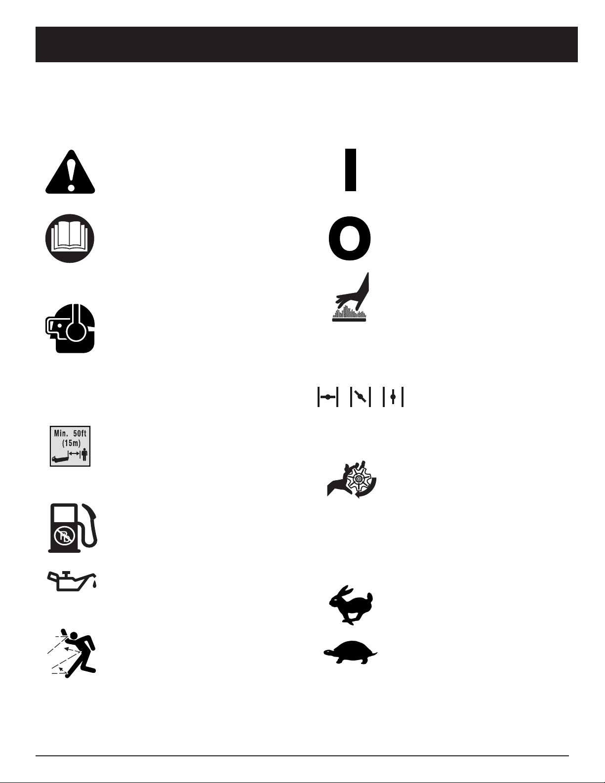
E6
NORMAS PARA UNA OPERACIÓN SEGURA
SIMBOLOS DE SEGURIDAD E INTERNACIONALES
Este manual del operador describe los símbolos y figuras de seguridad e internacionales que pueden aparecer en este
producto. Lea el manual del operador para obtener información completa acerca de la seguridad, ensamble, operación
y mantenimiento y reparación.
SIMBOLO SIGNIFICADO
• SIMBOLO DE ALERTA DE
SEGURIDAD
IIndica peligro, advertencia o
precaución. Puede ser utilizado junto
con otros símbolos o figuras.
• ADVERTENCIA - LEA EL MANUAL
DEL OPERADOR
Lea el manual del operador y siga todas
las advertencias e instrucciones de
seguridad. De no hacerlo, el operador
y/o los espectadores pueden sufrir
graves lesiones.
• USE PROTECCION OCULAR Y
AUDITIVA
ADVERTENCIA : Los objetos arrojados
por la unidad y el ruido fuerte pueden
causar graves lesiones oculares y
pérdida auditiva. Utilice protección
ocular que cumpla con las normas ANSI
Z87.1 y protección auditiva cuando
opere esta unidad. Use una careta
completa cuando la necesite.
•MANTENGA ALEJADOS A LOS
ESPECTADORES
ADVERTENCIA : Mantenga a todos
los espectadores, en especial a niños
y animales domésticos a por lo menos
50 pies (15 m) del área de corte.
• COMBUSTIBLE SIN PLOMO
Use siempre combustible limpio,
nuevo y sin plomo.
• INDICADOR DE ACEITE
Consulte el manual del operador para
obtener información acerca del tipo
correcto de aceite.
• LOS OBJETOS DESPEDIDOS Y LA
CUCHILLA ROTATIVA PUEDEN
CAUSAR GRAVES LESIONES
ADVERTENCIA: Manténgase alejado
de la salida del soplador. Nunca dirija
el soplador hacia usted mismo ni
hacia los demás. Los objetos pueden
salir despedidos del soplador. No
opere esta unidad sin los accesorios y
protecciones adecuados en su lugar.
SIMBOLO SIGNIFICADO
• CONTROL DE ENCENDIDO Y
APAGADO
ENCENDIDO /ARRANQUE /MARCHA
• CONTROL DE ENCENDIDO Y
APAGADO
APAGADO o PARADO
• ADVERTENCIA DE
SUPERFICIE CALIENTE
No toque un silenciador ni un cilindro
caliente. Puede quemarse. Estas partes
se calientan mucho con el uso. Luego de
apagarse permanecen calientes durante
un corto tiempo.
• CONTROL DEL OBTURADOR
1• Posición de obturación COMPLETA
2• Posición de obturación PARCIAL
3• Posición de MARCHA
• LAS SOPLADORAS–
CUCHILLAS GIRATORIAS DEL
ROTOR PUEDEN CAUSAR
LESIONES GRAVES
ADVERTENCIA: Pare el motor y
permita que el rotor se detenga
antes de instalar o cambiar tubos o
la bolsa, o antes de limpiar o hacerle
cualquier mantenimiento.
• CONTROL DEL REGULADOR
Indica la velocidad "ALTA" o "MAS
RAPIDA"
• CONTROL DEL REGULADOR
Indica la velocidad "MINIMA"
"BAJA" o "MAS BAJA"
12
3

E7
NORMAS PARA UNA OPERACIÓN SEGURA
APLICACIÓN
Como soplador:
• Limpieza de jardines, cocheras, entradas de
automóviles, pórticos, patios, alrededor de
paredes, cercos, etc.
Como aspirador:
• Recoger hojas, escombros livianos, etc.
Tubo del soplador
Entrada del
soplador
Tapa del
combustible
Control del regulador
Bujía de encendido
Mango de la cuerda
de arranque
Control de encendido
y apagado
CONOZCA SU UNIDAD
Ensamblada como un soplador
Gancho de la bolsa del
aspirador
Puerta de
aspiradora
Manija anterior
Tubos de
succión
Ensamblada como un aspirador
Bolsa del aspirador
Cierre relámpago
de la bolsa del
aspirador
Cebador
Control del
obturador
Cubierta del filtro de
aire / silenciador
Silenciador
Entrada del soplador / aspirador
Manija Posterior
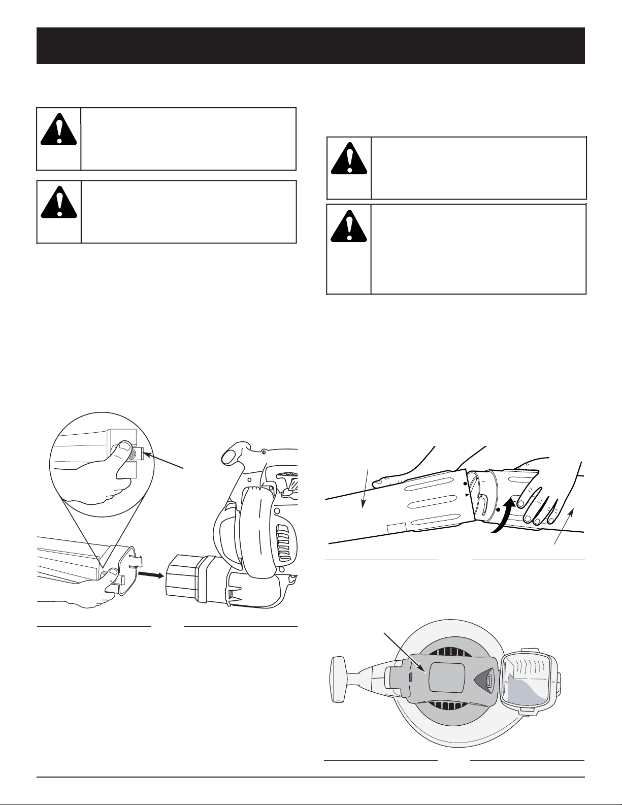
E8
INSTRUCCIONES DE ENSAMBLAJE
Orejetas
Tubo de succión
superior
Tubo de succión inferior
ENSAMBLE DE LA UNIDAD COMO SOPLADOR
Ensamble del tubo del soplador
NOTA: Si la unidad estaba ensamblada como una
unidad de aspiración, retire todas las partes del
aspirador y guárdelas en un lugar seguro para su
uso futuro.
Instalación
• Instale el tubo del soplador sobre la salida del
soplador y empuje hasta que ambas orejetas se
enganchen en su lugar (Fig. 1).
Remoción
• Retire el tubo del soplador presionando ambas
orejetas al mismo tiempo y tirando del tubo del
soplador hacia afuera (Fig. 1).
ENSAMBLE DE LA UNIDAD COMO ASPIRADOR
Para armar la unidad como una aspiradora, comience
quitándole el tubo del soplador. Consulte la sección
anterior.
Ensamble del tubo del aspirador
NOTA: Si la unidad estaba ensamblada como soplador,
retire todas las partes del soplador y guárdelas
en un lugar seguro para su uso futuro.
Instalación
1. Alinee la flecha del tubo de succión inferior con la
flecha del tubo de succión superior (Fig. 2).
2. Empuje el tubo de succión inferior dentro del tubo
superior, sujetándolo firmemente con ambas manos.
Gire el tubo de succión inferior hacia su derecha hasta
que encaje en el punto de detención y se asegure. (El
punto del tubo inferior se alinea con el punto del tubo
superior cuando estén ensamblados correctamente).
3. Voltee la unidad de modo que quede erecta en la
tapa del silenciador. La parte delantera de la unidad
y la puerta de la aspiradora deben darle el frente a
usted (Fig. 3).
Fig. 1
Fig. 2
Fig. 3
Puerta de
aspiradora
Para evitar
graves
lesiones personales, apague el motor y
espere que el propulsor se detenga antes
de conectar o retirar los tubos.
ADVERTENCIA:
Para evitar
graves
lesiones personales, apague el motor y
espere que el propulsor se detenga antes de
conectar o retirar tubos.
ADVERTENCIA:
Para evitar
graves
lesiones personales y el daño de la unidad, el
tubo del soplador debe estar instalado
mientras opere esta unidad como un soplador.
ADVERTENCIA:
Para evitar
graves
lesiones personales y el daño de la unidad,
instale siempre los tubos del aspirador, la
bolsa del aspirador y verifique que el cierre
relámpago de la bolsa del aspirador esté
completamente cerrado cuando opere esta
unidad como aspirador.
ADVERTENCIA:

E9
INSTRUCCIONES DE ENSAMBLAJE
4. Inserte un destornillador de cabeza plana en la
ranura en el extremo inferior de la puerta de la
aspiradora. Establezca contacto con la abrazadera
de cierre de la puerta de aspiradora y empuje hacia
adentro y arriba (Fig. 4). Después tire de la puerta de
la aspiradora y manténgala abierta.
5. Mientras mantiene abierta la puerta de la aspiradora,
localice el tubo de la aspiradora armado (armado en
el Paso 2). Ponga el tubo de modo que el área plana
esté de frente a la puerta de la aspiradora. Las
ranuras en el costado del tubo se alinearán con las
pequeñas lengüetas en la admisión del impulsor
(Fig. 5). Desde el exterior, alinee la pequeña flecha
en el tubo de aspiradora con el punto que está en la
admisión del impulsor.
6. Empuje el tubo de aspiradora con firmeza y agárrelo
con ambas manos. Gire el tubo en sentido horario
tanto como sea posible hasta que encaje en el retén
y trabe. Cuando está debidamente armado, el punto
del tubo de aspiradora se alineará con el punto de la
admisión del impulsor.
Abrazadera
de cierre
Fig. 4
Ranura de la puerta de
aspiradora
Admisión del
impulsor
Ranura del tubo
de aspiradora
Fig. 5
Remoción
1. Desenganche la bolsa.
2. Saque la bolsa del aspirador presionando ambas
orejetas en el codo de la bolsa del aspirador al
mismo tiempo y tirando hacia afuera del soplador
(Fig. 6).
3. Instale el tubo del soplador para armar la unidad
como un soplador.
4. Cerciórese de que la puerta de aspiradora esté
cerrada con seguridad.
Instalación la bolsa del aspirador
7. Instale el tubo de la bolsa del aspirador sobre la
salida del soplador y empuje hasta que las orejetas
de la base se enganchan en su lugar (Fig. 6).
8. Enganche la bolsa de la aspiradora al gancho de la
bolsa de aspiradora situado en la parte inferior de la
unidad.
Fig. 6
Gancho de la bolsa
de aspiradora
Codo
Orejetas
Área
Plana
Orejetas
Nunca
opere la
unidad en la configuración de soplador sin
que la puerta de la aspiradora esté fija y
cerrada con pestillo.
ADVERTENCIA:
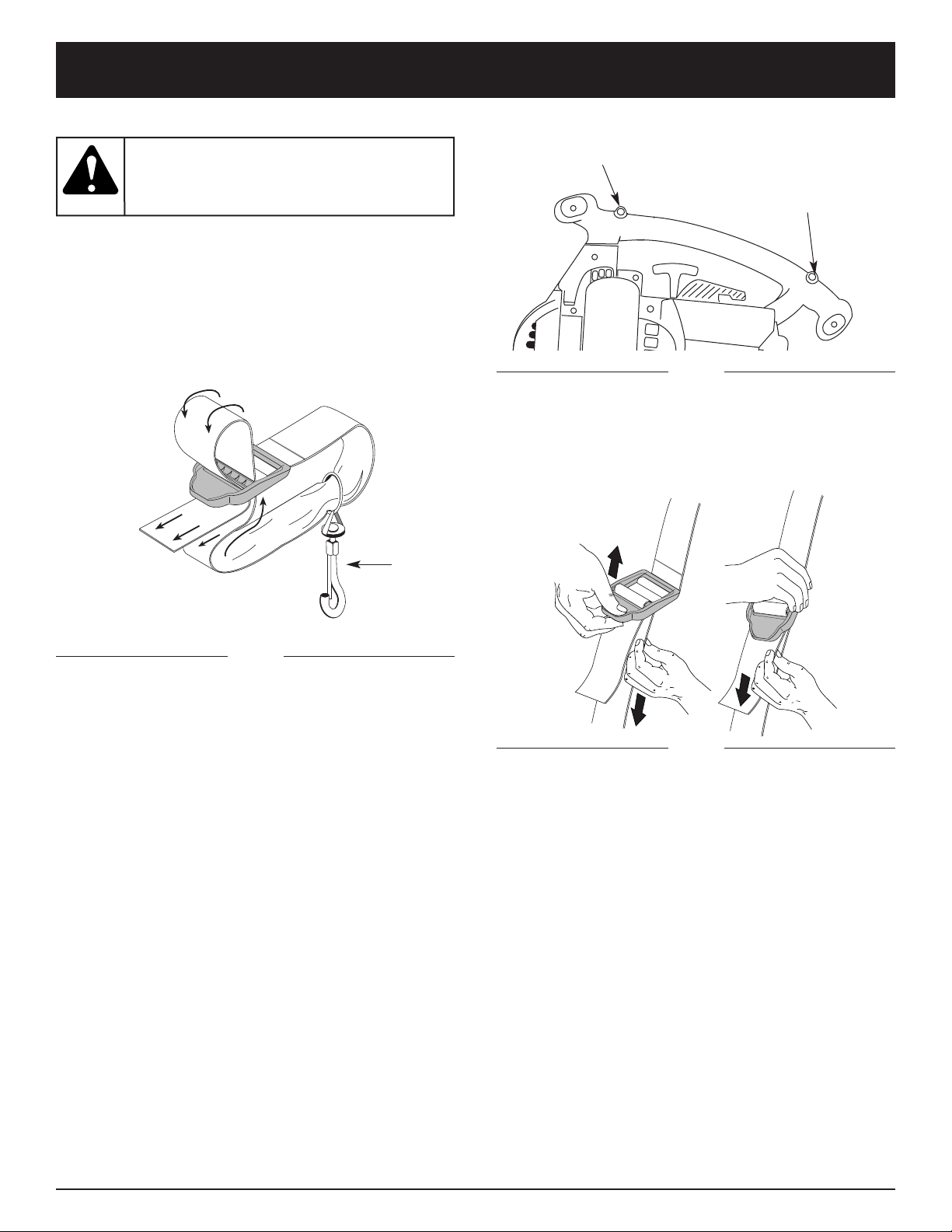
E10
INSTRUCCIONES DE ENSAMBLAJE
Fig. 9
3. Encaje la abrazadera en los herrajes de soporte en la
parte anterior o posterior de la manija. Abróchela a la
parte anterior de la manija al usar la unidad como un
soplador, y abróchela a la parte posterior de la manija
al usar la unidad como una aspiradora (Fig. 8).
4.Ajuste la longitud a la medida del operador. Tire de la
lengüeta para alargarla, tire de la correa para acortarla
(Fig. 9).
INSTALACION DEL ARNES
1. Pase la correa por el centro de la hebilla.
2. Pase la correa sobre la barra transversal y hacia
abajo por la ranura de la hebilla (Fig. 7).
Fig. 7
Conecte aquí
para soplar
Conecte aquí
para aspirar
Fig. 8
Para evitar
graves
lesiones personales, use siempre el arnés del
hombro cuando utilice la cuchilla de corte.
ADVERTENCIA:
Gancho
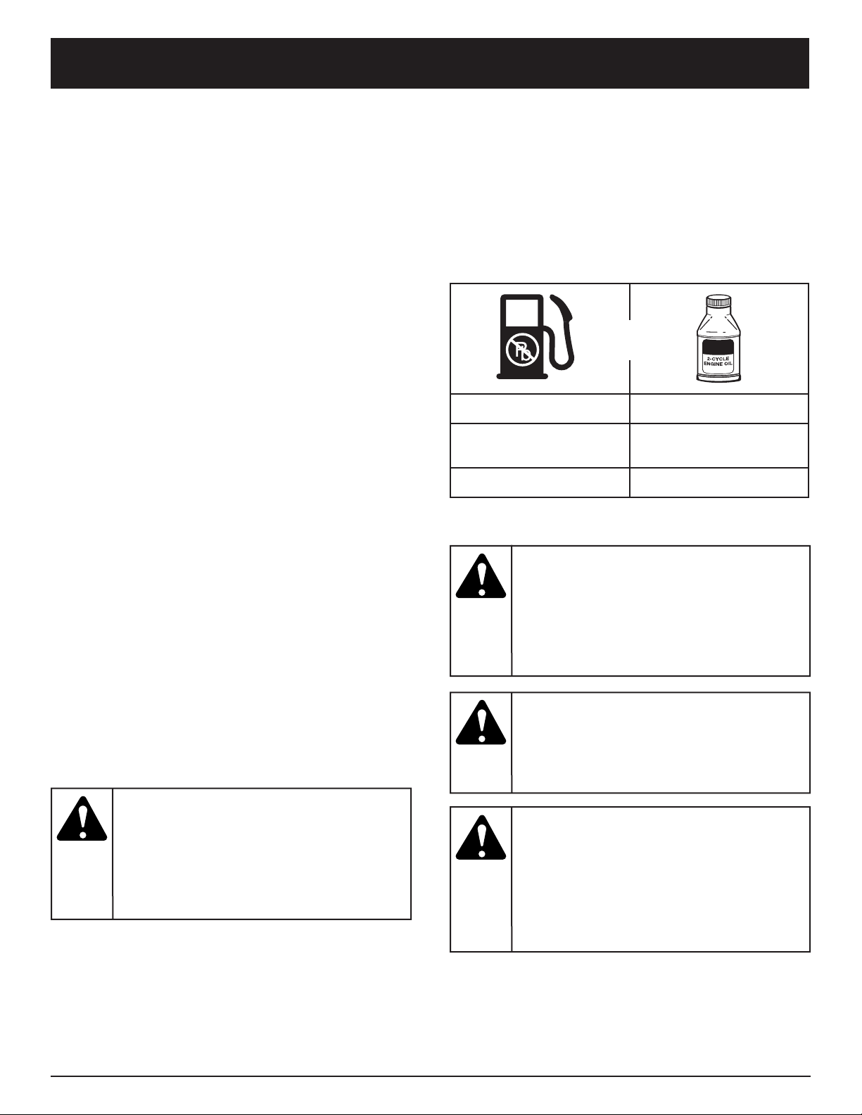
E11
INFORMACION DEL ACEITE Y DEL COMBUSTIBLE
NOTA: Elimine la mezcla vieja de aceite y combustible de
acuerdo con los reglamentos federales, estatales
y locales.
INSTRUCCIONES PARA MEZCLAR EL
ACEITE Y EL COMBUSTIBLE
El combustible viejo o mal mezclado son los motivos
principales del mal funcionamiento de la unidad.
Asegúrese de usar combustible nuevo, limpio y sin
plomo. Siga las instrucciones en detalle para mezclar
correctamente el aceite y el combustible.
Definición de los combustibles de mezcla
Los combustibles actuales con frecuencia son una mezcla
de gasolina y oxigenantes como por ejemplo etanol,
metanol o MTBE (éter). El combustible mezclado con
alcohol absorbe agua. Una cantidad tan pequeña como el
1% de agua en el combustible puede causar la separación
del combustible y el aceite. Forma ácidos cuando está
almacenado. Cuando use combustible mezclado con
alcohol, use combustible nuevo (de menos de 60 días).
Uso de combustibles de mezcla
Si usted opta por usar un combustible de mezcla o si su
uso es inevitable, tome las precauciones
recomendadas.
• Use siempre una mezcla fresca de combustible según
lo indica su manual del operador.
• Agite siempre la mezcla de combustible antes de
cargarlo en la unidad.
• Drene el tanque y haga funcionar el motor en seco
antes de guardar la unidad.
Uso de aditivos en el combustible
La botella de aceite de 2 ciclos que vino con su unidad
contiene un aditivo en el combustible que ayudará a
inhibir la corrosión y a reducir la formación de depósitos
de goma. Se recomienda que use sólo el aceite de 2
ciclos con esta unidad.
Si es inevitable, use un buen aceite de 2 ciclos
elaborado para motores enfriados por aire junto con un
aditivo para el combustible como por ejemplo el
estabilizador de gasolina STA-BIL
®
o similar. Agregue
23 mL (0,8 onzas) de aditivo de combustible por galón
de combustible de acuerdo con las instrucciones del
envase. NUNCA agregue aditivos directamente en el
tanque de combustible de la unidad.
Mezcle bien la proporción correcta de aceite para motor
de 2 ciclos y gasolina sin plomo en una lata de
combustible por separado. Use una proporción de 40:1
de combustible y aceite. No los mezcle directamente en
el tanque de combustible de la unidad. Consulte las
proporciones específicas de mezcla de gasolina y aceite
en la tabla siguiente.
NOTA: 3,8 litros (un galón) de gasolina sin plomo
mezclada con una botella de 95 mL (3,2 onzas)
de aceite de 2 ciclos es una proporción de 40:1
de combustible y aceite.
GASOLINA SIN PLOMO ACEITE DE 2 CICLOS
3,8 LITROS
(1 GALON de EE.UU.)
95 mL
(3,2 ONZAS FLUIDAS)
1 LITRO 25 mL
+
PROPORCION DE LA MEZCLA = 40 : 1
Para que el
motor
funcione correctamente y con la mayor
fiabilidad, preste mucha atención a las
instrucciones de mezcla de aceite y
combustible del envase de aceite de 2 ciclos.
El uso de combustible mezclado en forma
incorrecta puede dañar seriamente el motor.
PRECAUCION:
Cargue el
combustible en un área exterior limpia y bien
ventilada. Limpie de inmediato todo
combustible que se haya derramado. Evite
crear una fuente de encendido con el
combustible derramado. No arranque el
motor hasta que se hayan evaporado los
gases del combustible.
ADVERTENCIA:
Saque la
tapa del
combustible lentamente para evitar lesionarse
con el rociado del combustible. No opere
nunca la unidad sin la tapa del combustible
firmemente colocada en su lugar.
ADVERTENCIA:
La
gasolina es
muy inflamable. Los gases pueden explotar
si se encienden. Apague siempre el motor y
espere que se enfríe antes de cargar el
tanque de combustible. No fume mientras
llena el tanque. Mantenga las chispas y las
llamas lejos del área.
ADVERTENCIA:

E12
INSTRUCCIONES DE ARRANQUE Y APAGADO
INSTRUCCIONES DE ARRANQUE
Fig. 10
Fig. 11
INTRUCCIONES DE APAGADO
1. Coloque el control del regulador en posición de mínima
( ). Deje enfriar el motor en mínima.
2. Coloque el control de encendido y apagado en posición de
APAGADO (O).
1. Mezcle la gasolina con el aceite. Llene el tanque de
combustible con la mezcla de combustible / aceite. Vea las
Instrucciones para Mezcla de Aceite y Combustible.
NOTA: No hay necesidad de encender la unidad. El Control
de Parada Encendido/Apagado (On/Off) está en la
posición Encendido (ON) (I), en todo momento.
2. Oprima completamente el cebador y suéltelo 10 veces.
Hágalo lentamente. Se deberá ver un poco de combustible
en el cebador y en las tuberías de alimentación de
combustible. Si no puede ver el combustible en el cebador,
oprímalo y suéltelo tantas veces como sea necesario hasta
que vea combustible en el mismo.
3. Coloque la palanca azul en Posición 1 (Fig. 11).
4. Ponga la unidad en la posición de arranque (Fig. 12 o
Fig. 13). Coloque el control del regulador en la posición
de RÁPIDA () (Fig.10).
5. Tire del cordón de arranque hasta 5 veces.
6. Coloque la palanca azul en Posición 2.
7. Tire de la cuerda de arranque rápidamente de 1 a 3
veces para arrancar el motor.
8. Mantenga oprimido el regulador y deje que el motor se
caliente durante 15 a 30 segundos.
9. Coloque la palanca azul en Posición 3. La unidad está
lista para usarse.
SI... El motor no arranca, regrese al paso 2.
SI...
El motor no arranca después de varios intentos,
coloque la palanca azul en la Posición 3 y coloque el
control del regulador en la posición de RÁPIDA
()
.
Hale la cuerda del arranque con fuerza de 3 a 8 veces.
El motor deberá arrancar. Si no sucede así, repita el
procedimiento.
SI SE CALIENTA... El motor ya está caliente, cerciórese
de que el control de Encendido/Apagado (On/Off) esté
en la posición de Encendido (ON) y arranque la unidad
con la palanca azul en la Posición 2. Después de que la
unidad arranque, mueva la palanca azul a la Posición 3.
Posición de
Arranque de
la Aspiradora
Posición de
Arranque del
Soplador
Fig. 12
Fig. 13
Use esta unidad
sólo en un área
exterior bien ventilada. Los gases de escape de monóxido
de carbono pueden ser letales en un área cerrada.
ADVERTENCIA:
Evite los arranques
accidentales. Esté
en posición de arranque cuando hale la cuerda
(Fig. 12 y 13).
Tampoco ponga la unidad sobre ninguna superficie
excepto sobre una superficie limpia y sólida, mientras
se pone en marcha. Los desechos tales pueden ser
absorbidos por la toma de aire y ser lanzados por la
abertura de descarga, causándole daños a la unidad,
propiedad o causándole lesiones graves a los
espectadores o al operardor.
ADVERTENCIA:
Siempre quite
la bolsa de
recolección antes de reabastecer la unidad con
combustible. La bolsa se puede convertir en un
peligro de incendio cuando se satura de combustible.
ADVERTENCIA:
Bulbo cebador
Cuerda de
arranque
Cuerda de
arranque
Control de apagado
On/Off
Control del regulador
Mínima
Rápida
Palanca azul
Posición 1
Posición 3
Posición 2

E13
INSTRUCCIONES DE OPERACIÓN
SOSTENIMIENTO DE LA SOPLADORA/
ASPIRADORA
Antes de operar esta unidad, párese en la posición de
operación. Verifique lo siguiente:
• El operador está vestido con la ropa apropiada tal
como botas, gafas de protección, protección auditiva,
guantes, pantalones largos y camisa de manga larga.
• Si las condiciones son polvorientas, el operador lleva
puesta una máscara.
• La unidad se encuentra en buen estado de funcionamiento.
• Los tubos y protectores están puestos y asegurados
en su lugar.
CONSEJOS ÚTILES SOBRE LA OPERACIÓN
• Asegúrese que la unidad no apunte hacia desechos
sueltos o personas antes de ponerla en marcha.
•Compruebe que la unidad se encuentre en buen
estado de funcionamiento. Verifique que los tubos y
protectores estén puestos y asegurados en su lugar.
• Se recomienda sostener la unidad con ambas manos
cuando maneje la sopladora a la altura de la cintura o
en ángulos incómodos.
•Se requiere el uso de protección auditiva para reducir
el riesgo de pérdida auditiva asociada con los niveles
de sonido.
• Opere el equipo solamente durante horas razonables — no
muy temprano en las mañanas ni muy tarde en las noches,
cuando la gente se pueda molestar. Acate las horas
detalladas en las ordenanzas locales. La recomendación
usual es de 9:00 am a 5:00 pm, de lunes a sábado.
• Limite el número de equipos que se usen
simultáneamente, para reducir los niveles de ruido.
• Opere las sopladoras motorizadas a la menor velocidad
posible, para hacer el trabajo y reducir los niveles de ruido.
• Verifique el estado del equipo antes del
funcionamiento, especialmente el tubo de escape,
tomas de aire y filtros de aire.
• Use rastrillos y escobas para esparcir los desechos
antes de soplarlos.
• Remoje ligeramente las superficies o use un
aditamento para rociar cuando haya agua disponible y
se encuentre bajo condiciones polvorientas.
• Conserve agua mediante el uso de sopladoras
motorizadas en vez de usar mangueras para muchas
de las aplicaciones de prados y ajardinado, incluyendo
áreas tales como canales, mallas, patios, parrillas,
pórticos y jardines.
• Tenga cuidado con los niños, animales domésticos,
ventanas abiertas y automóviles recién lavados, y
sople los desechos en forma segura.
• Use la extensión completa de la boquilla sopladora de
manera que el chorro de aire salga cerca al suelo.
• Limpie después de usar las sopladoras y otros equipos.
Deposite los desechos en recipientes para la basura.
PROCEDIMIENTO DE OPERACIÓN PARA LA
SOPLADORA
1 Use la sopladora para árboles, arbustos, macizos de
flores y zonas de limpieza difícil (Fig. 14).
2.Use la unidad alrededor de edificios y para otras
limpiezas normales (Fig. 14).
3.Use la sopladora para paredes, salientes, cercas y
mallas (Fig. 15).
Fig. 14
Fig. 15
Para evitar
lesiones
personales graves, póngase gafas de
seguridad en todo momento cuando maneje
esta unidad. Póngase una máscara o máscara
para polvo en sitios que sean polvorientos.
ADVERTENCIA:
Dependiendo
del modelo,
asegúrese que los tubos de soplado o de
succión y la bolsa de recolección estén en su
lugar antes de operar la unidad, para evitar
causarse lesiones personales graves o
causárselas a otras personas, u ocasionarle
daños a la unidad.
ADVERTENCIA:

E14
INSTRUCCIONES DE OPERACIÓN
Fig. 16
OPERACION COMO ASPIRADOR
Antes de operar la unidad, verifique lo siguiente:
• El operador viste ropa adecuada, como botas, lentes o
gafas de protección, protección para los oídos y
audición, guantes, pantalones largos y camisa de
manga larga.
• Si el trabajo levanta polvo, se utiliza una máscara para
polvo o una máscara facial.
• La unidad está en buenas condiciones de
funcionamiento. Los tubos de aspiración y la bolsa del
aspirador están colocados en su lugar y asegurados.
• El arnés de la bolsa del aspirador está colocado en su
lugar y bien ajustado.
Use la unidad para aspirar escombros chicos, hojas,
papel, etc.
Sostenga el aspirador, inclinando ligeramente el tubo de
aspiración, y use un movimiento de barrido para recoger
el escombro chico (Fig. 16). El escombro fluirá dentro de
la bolsa del aspirador. Los objetos como las hojas
pequeñas y las ramas pequeñas serán trituradas a
medida que pasan a través del bastidor del ventilador,
permitiendo que la bolsa del aspirador cargue más
escombros.
Cuando la bolsa está llena, la aspiración disminuirá en
forma notable. Apague la unidad y espere que el
propulsor se detenga antes de abrir el cierre relámpago
de la bolsa. Abra el cierre relámpago de la bolsa y vacíe
su contenido antes de continuar. Lea Vaciado de la
Bolsa del Aspirador.
Vaciado de la bolsa del aspirador
1. Proteja sus ojos y use una máscara contra el polvo,
abra el cierre relámpago de la bolsa del aspirador y
vaciar el contenido en una bolsa o recipiente de
basura.
2. Dé vuelta la bolsa hacia fuera luego del vaciado
inicial y agite con fuerza para eliminar el polvo y el
escombro.
3. Cierre el cierre relámpago y vuelva a instalar la bolsa
del aspirador.
To prevent serious
personal injury or
damage to the unit, always install vacuum
tubes, vacuum bag and make sure the
vacuum bag is completely zipped closed
when operating this unit as a vacuum.
WARNING:
Evite
situaciones que puedan causar que la bolsa del
aspirador se prenda fuego. No opere la
unidad cerca de una llama. No aspire
cenizas calientes de hogares, fosos de
parrillas, pilas de maleza, etc. No aspire
cigarros ni cigarrillos desechados a menos
que las cenizas estén completamente frías.
ADVERTENCIA:
Como
aspirador,
la unidad está diseñada para recoger material
seco como hojas, césped, ramas pequeñas y
trocitos de papel. Para evitar graves lesiones
personales, no intente aspirar residuos
húmedos ni agua estancada, ya que esto
puede causar el daño del Soplador /
Aspirador. Para evitar graves daños en el
propulsor, no aspire metal, vidrios rotos, etc.
ADVERTENCIA:
Para evitar
graves
lesiones personales, nunca abra el cierre
relámpago de la bolsa sin detener primero
la unidad.
ADVERTENCIA:
Cuando
retire los
tubos superior e inferior del aspirador,
verifique que la puerta del aspirador esté
cerrada a presión antes de usar la unidad,
para evitar dañar el propulsor.
ADVERTENCIA:
Para evitar
graves
lesiones personales, apague la unidad y
espere que el propulsor se detenga antes
de abrir la puerta del aspirador o de instalar
o retirar la bolsa del aspirador.
ADVERTENCIA:

E15
INSTRUCCIONES DE MANTENIMIENTO Y REPARACIÓN
NOTA: Algunos procedimientos de mantenimiento
pueden requerir el uso de herramientas o
habilidades especiales. Si no está seguro acerca
de estos procedimientos, lleve su unidad a un
establecimiento de reparación, persona o
distribuidor de servicio autorizado que arregle
motores para uso fuera de la carretera.
PROGRAMA DE MANTENIMIENTO
Estos procedimientos requeridos para el mantenimiento
deben ser realizados con la frecuencia indicada en la
tabla. Deben ser incluidos como parte de toda puesta a
punto de cada temporada.
NOTA: El mantenimiento, la sustitución o arreglo de
dispositivos para el control de emisiones y
sistemas pueden ser hechos por cualquier
establecimiento de reparación, persona o
proveedor de servicio autorizado que arregle
motores para uso fuera de la carretera.
A fin de garantizar el máximo desempeño del motor,
puede ser necesario inspeccionar la lumbrera de escape
del motor después de 50 horas de funcionamiento. Si
usted observa pérdida de RPM, funcionamiento deficiente
o falta general de aceleración, es posible que sea
necesario realizar este mantenimiento. Si usted considera
que su motor necesita esta inspección, haga que un
establecimiento de reparación, persona o proveedor de
servicio autorizado que arregle motores para uso fuera de
la carretera le preste el servicio. NO intente realizar este
proceso usted mismo ya que puede ocasionar daños al
motor producto de los contaminantes que se encuentran
en el proceso de limpieza de la lumbrera.
FRECUENCIA MANTENIMIENTO REQUERIDO CONSULTE
Antes de arrancar el motorLlene el tanque de combustible con la mezcla correcta de aceite y combustible
Página E11
Cada 10 horass Limpie y vuelva a aceitar el filtro de aire Página E15
Cada 25 horass
Examine el parachispas y límpielo
Inspeccione la condición y la separación de la bujía de encendido
Página E16
Página E18
Cada 50 horas
Inspeccione si la lumbrera de escape y la rejilla del parachispas están
tupidas u obstruidas para garantizar los niveles máximos de rendimiento
Página E16
2. Saque los cuatro (4) tornillos que sostienen la
cubierta del silenciador / filtro de aire (Fig. 17). Use
un destornillador de broca Torx N° T20.
3. Saque la cubierta del motor. No la fuerce.
Limpieza del Filtro de Aire
Limpie y vuelva a aceitar el filtro de aire cada 10 horas de
operación. Es una de las partes cuyo mantenimiento es
importante. No mantener debidamente su filtro de aire
puede resultar en funcionamiento inadecuado o puede
causar daño permanente a su motor.
1. Saque la cubierta del silenciador / filtro de aire. Lea la
sección de Remoción de la cubierta del silenciador /
filtro de aire.
2. Gire la tapa y ubique el filtro de aire adentro. Saque
el filtro de aire de adentro de la tapa del filtro de aire /
silenciador (Fig. 18).
Filtro de
aire
Fig. 18
Fig. 19
Tapa interior del
silenciador
MANTENIMIENTO DEL FILTRO DE AIRE
Remoción de la cubierta del silenciador/filtro de aire
1. Coloque la palanca azul en Posición
2
.
NOTA: La palanca azul debe estar en Posición 2 (Fig. 17)
para sacar la cubierta del silenciador / filtro de
aire.
Palanca azul
Tornillos
Tornillos
Posición 2
Fig. 17
Para evitar
lesiones
personales graves, nunca realice mantenimiento ni reparaciones con la unidad
funcionando. Realice siempre el mantenimiento
y las reparaciones con la unidad fría.
Desconecte el cable de la bujía de encendido
para cerciorarse de que la unidad no arrancará.
ADVERTENCIA:
Para evitar
graves
lesiones personales, apague siempre su
recortador y espere que se enfríe antes de
limpiarlo o realizar todo tipo de mantenimiento.
ADVERTENCIA:

E16
INSTRUCCIONES DE MANTENIMIENTO Y REPARACIÓN
Fig. 20
Fig. 21
3. Lave el filtro con agua y detergente (Fig. 19).
Enjuague bien el filtro. Escurra el exceso de agua.
Déjelo secar por completo.
4. Aplique suficiente aceite limpio SAE 30 para recubrir
ligeramente el filtro (Fig. 20).
5. Apriete el filtro para esparcir y retirar el exceso de
aceite (Fig. 21).
6. Cambie el filtro de aire dentro de la tapa del filtro de
aire / silenciador (Fig. 18).
NOTA: Si opera la unidad sin el filtro de aire y el
ensamble de la cubierta del silenciador / filtro de aire,
su garantía quedará ANULADA.
Reinstalación de la cubierta del silenciado /filtro de aire
1. Coloque la cubierta del silenciador / filtro de aire
sobre la parte posterior del carburador y del
silenciador. Alinee los orificios de los tornillos.
2. Inserte los cuatro (4) tornillos en los orificios de la
cubierta del silenciador / filtro de aire (Fig. 17) y
ajústelos. No los ajuste demasiado.
Fig. 22
Si el
conjunto
del deflector de emisiones no se aprieta
fijamente se puede caer y causarle daño a la
unidad y posibles lesiones personales graves.
ADVERTENCIA:
MANTENIMIENTO DEL PARACHISPAS
NOTA: El flujo de las emisiones puede ser en una
dirección solamente: APARTÁNDOSE del motor.
Preste mucha atención a cómo se ensambla el
silenciador, de modo que lo pueda volver a
armar exactamente como está. El no hacerlo así
dañará a la unidad y pudiera causar lesiones
personales graves.
1. Quite el filtro de aire / tapa del silenciador. Ver
Remoción de la Tapa del Filtro / Silenciador.
2. Localice el silenciador, pero no lo quite. Busque los
dos (2) tornillos en la parte inferior del silenciador
(Fig. 22). Estos dos tornillos unen el conjunto de
deflector de escape y la pantalla del parachispas a la
parte inferior del silenciador. Quite los dos (2)
tornillos usando una llave torx No. 20 o un
destornillador plano.
3. Utilizando un pequeño destornillador plano,
palanquee con cuidado hacia arriba la pantalla del
parachispas del agujero encastrado, fijándose que la
parte “levantada” de la pantalla del parachispas
quede dentro del agujero encastrado. Retire la
pantalla del parachispas del silenciador.
4. Limpie la rejila del parachispas con un cepillo de
cerdas metálicas. Cámbiela si está dañada o si no la
puede limpiar completamente.
5. Vuelva a instalar la pantalla del parachispas
colocando la parte “levantada” de la pantalla dentro
del agujero empotrado del silenciador. Cerciórese de
que la pantalla del parachispas quede plana contra el
silenciador.
6. Coloque la placa del parachispas encima del
parachispas con el lado “levantado” hacia arriba
mirando al motor (Fig. 22).
7. Coloque el capó del parachispas encima de la placa
del parachispas con el lado “levantado” hacia arriba
y la apertura mirando en dirección CONTRARIA al
motor (Fig. 22). Asegúrese de que el escape se dirija
en dirección CONTRARIA al motor.
8. Vuelva a colocar los dos tornilos que quitó en el Paso
2 y apriételos firmemente.
9. Reinstale la tapa del filtro de aire / silenciador.
Tornillos
Silenciador
Pantalla del
parachispas
Placa del
parachispas
Capó del
parachispas
Agujero que ha
quedado
abierto
El conjunto del capó
del parachispas
incluye:
Placa del parachispas
Capó del parachispas
y Tornillos
Abertura
Motor

E17
INSTRUCCIONES DE MANTENIMIENTO Y REPARACIÓN
AJUSTE DEL CARBURADOR
La velocidad lenta del motor puede ser ajustada por la
cubierta del silenciador / filtro de aire (Fig. 23).
NOTA: Los ajustes realizados sin cuidado pueden dañar
seriamente su unidad. Los ajustes del carburador
deben ser realizados por un proveedor de
servicio autorizado.
Controle la mezcla del combustible
Una mezcla incorrecta o vieja de combustible es en
general el motivo por el cual la unidad no funciona
adecuadamente. Drene y vuelva a llenar el tanque con
combustible nuevo y bien mezclado antes de hacer
ningún ajuste. Consulte la Información sobre Aceite y
Combustible.
Limpie el filtro de aire
La condición del filtro de aire es importante para la
operación de la unidad. Un filtro de aire sucio limitará el
flujo de aire y cambiará la mezcla de combustible y aire
en el carburador. Esto con frecuencia se confunde con
un carburador mal ajustado. Verifique la condición del
filtro de aire antes de ajustar el tornillo de marcha lenta.
Consulte Mantenimiento del Filtro de Aire.
Ajuste del tornillo de marcha lenta
El control de la mezcla de combustible, la limpieza del
filtro de aire y el ajuste del tornillo de marcha lenta deben
resolver la mayoría de los problemas del motor.
De no ser así y si:
• El motor no funciona en mínima
• El motor fluctúa o se para al acelerar
• Existe una pérdida de fuerza motriz
Lleve el carburador a un proveedor de servicio
autorizado para que lo ajuste.
Tornillo de
marcha en vacío
Fig. 23
Si luego de controlar la mezcla de combustible y limpiar
el filtro de aire el motor aún no funciona en mínima,
ajuste el regulador de velocidad mínima de este modo.
1. Arranque el motor y déjelo funcionar en una velocidad
mínima alta durante un minuto para que se caliente.
La unidad
deberá
estar en marcha durante el ajuste de velocidad
lenta. Use ropa que lo proteja y cumpla con
todas las instrucciones de seguridad para
prevenir graves lesiones personales.
Asimismo, no apoye la unidad sobre ninguna
superficie excepto un área limpia y dura
mientras realiza estos ajustes. Los
escombros como grava, arena, polvo,
césped, etc. pueden ser absorbidos por la
entrada de aire y salir despedidos por la
abertura de descarga, dañando la unidad, la
propiedad, o causando lesiones graves al
operador y a los espectadores.
ADVERTENCIA:
2. Mueva el control del regulador y deje que el motor
funcione en mínima. Si el motor se para, inserte un
destornillador pequeño Phillips o de vástago plano
en el orificio de la cubierta del filtro de aire /
silenciador (Fig. 23). Gire el regulador de velocidad
mínima hacia dentro en sentido horario 1/8 de vuelta
por vez (según sea necesario) hasta que el motor
funcione en velocidad mínima en forma continua.
3. Si parece que la unidad está funcionando con una
mínima demasiado rápida, gire el regulador de velocidad
mínima en sentido antihorario 1/8 de vuelta por vez
(según sea necesario), para reducir la velocidad mínima.

E18
Fig. 24
0,5 mm
(0,020 pulg)
CAMBIO DE LA BUJIA DE ENCENDIDO
Use una bujía de encendido Champion RDJ7Y (o
similar). La separación correcta es de 0,5 mm (0,020
pulgadas). Retire la bujía luego de cada 25 horas de
operación e inspeccione su estado.
1. Apague el motor y espere que se enfríe. Tome el
alambre de la bujía con firmeza y sáquelo de la bujía
de encendido.
2. Limpie alrededor de la bujía de encendido. Saque la
bujía de encendido de la cabeza del cilindro girando
una llave de casquillo de 16mm (5/8) de pulgada en
sentido antihorario.
3. Cambie las bujías que estén rajadas, sucias o
deterioradas. Fije la separación de aire a 0,5 mm
(0,020 pulgadas) utilizando un calibrador (Fig. 24).
4. Instale una bujía de encendido con la separación
correcta en la cabeza del cilindro. Ajuste girando la
llave de casquillo de 16 mm (5/8 pulg.) en sentido
horario hasta que esté ajustada sin huelgo.
Si usa una llave de torsión, ajuste a:
12,3-13,5 N•m (110-120 pulg.•libras).
No ajuste demasiado.
No limpie
con chorro
de arena, ni raspe ni limpie los electrodos.
El motor podría dañarse si penetran
pequeñas partículas en el cilindro.
PRECAUCION:
1. Oprima y sostenga el control de apagado On/Off en
la posición de apagado (STOP) (O) hasta que el
motor se apague por completo (Fig. 10).
2. Desconecte el cable de la bujía de encendido para
evitar que la unidad arranque.
3. Quite el tubo del soplador/aspirador y la bolsa del
aspirador.
4. Saque con cuidado el material que está obstruyendo
el tubo o el propulsor. Inspeccione las cuchillas para
verificar que no hayan ocurrido daños. Gire las
cuchillas del propulsor a mano para asegurar que
haya desbrozado la obstrucción por completo.
5. Vuelva a instalar la bolsa del aspirador y el tubo del
soplador / aspirador.
6. Vuelva a conectar el cable de la bujía de encendido.
DESBROCE DE UN TUBO / PROPULSOR
OBSTRUIDO
INSTRUCCIONES DE MANTENIMIENTO Y REPARACIÓN
Para evitar
graves
lesiones personales, verifique que la unidad
esté apagada entes de limpiarla o realizar
cualquier tipo de mantenimiento en ella.
ADVERTENCIA:
Para evitar
graves
lesiones personales, use siempre guantes
para protegerse contra las cuchillas del
propulsor o contra otros objetos afilados.
ADVERTENCIA:

E19
LIMPIEZA
Use un cepillo pequeño para limpiar la parte exterior de
la unidad. No use detergentes fuertes. Los limpiadores
domésticos que contienen aceites aromáticos como pino
y limón, y con solventes como el queroseno pueden
dañar el bastidor de plástico y la manija. Seque toda la
humedad con un paño suave.
LIMPIEZA DE LA BOLSA DEL ASPIRADOR
1. Vacíe la bolsa luego de cada uso para evitar el
deterioro y la obstrucción del flujo de aire, lo cual
reducirá el rendimiento del aspirador.
2. Proteja sus ojos y use una máscara para el polvo,
limpie la bolsa según sea necesario. Dé vuelta la
bolsa hacia fuera luego del vaciado inicial y agite con
fuerza para eliminar el polvo y los escombros.
3. Lave la bolsa una vez por año o con mayor
frecuencia si es necesario:
a. Saque la bolsa del aspirador.
b. Dé vuelta la bolsa hacia fuera.
c. Cuelgue la bolsa.
d. Lave bien la bolsa con una manguera.
e. Cuelgue la bolsa para que se seque.
f. Dé vuelta la bolsa con el lado correcto hacia
fuera y vuelva a instalarla.
ALMACENAMIENTO
• No guarde nunca la unidad con combustible en el
tanque donde los vapores puedan llegar a una llama o
chispa.
• Espere que el motor se enfríe antes de guardar la
unidad.
•Guarde la unidad bajo llave para prevenir el uso por
personas no autorizadas y daños.
•Guarde la unidad en un área seca y bien ventilada.
•Guarde la unidad fuera del alcance de los niños.
INSTRUCCIONES DE MANTENIMIENTO Y REPARACIÓN
ALMACENAMIENTO PROLONGADO
Si planea guardar la unidad durante un largo período de
tiempo, siga el siguiente procedimiento para su
almacenamiento.
1. Drene todo el combustible del tanque de
combustible en un recipiente que contenga la misma
mezcla de combustible de 2 ciclos. No use
combustible que haya permanecido guardado
durante más de 60 días. Deseche la mezcla vieja de
combustible y aceite de acuerdo a las regulaciones
federales, estatales y locales.
2. Arranque el motor y déjelo funcionar hasta que se
ahogue. Esto asegura que todo el combustible ha
sido drenado del carburador.
3. Espere que el motor se enfríe. Retire la bujía de
encendido y coloque alrededor de 30 mL (1 onza) de
cualquier aceite para motor de 2 ciclos buena calidad
dentro del cilindro. Tire de la cuerda de arranque
lentamente para esparcir el aceite. Vuelva a instalar
la bujía de encendido.
NOTA: Saque la bujía de encendido y drene todo el
aceite del cilindro antes de intentar arrancar el
recortador después de su almacenamiento.
4. Limpie bien la unidad e inspeccione para ver si
existen partes flojas o dañadas. Repare o cambie las
partes dañadas y ajuste los tornillos, tuercas o
pernos que puedan estar flojos. La unidad está ahora
lista para ser guardada.
TRANSPORTE
• Espere que el motor se enfríe antes de transportar
• Asegure la unidad durante su transporte.
•Drene el combustible de la unidad.
• Ajuste la tapa del combustible antes de transportar.
Para
evitar
graves lesiones personales, apague
siempre su unidad y espere que se enfríe
antes de limpiarlo o realizar cualquier tipo
de mantenimiento.
ADVERTENCIA:

E20
RESOLUCIÓN DE PROBLEMAS
CAUSA ACCIÓN
El combustible es viejo o está mal mezclado Drene el tanque de gasolina / Agregue mezcla de
combustible nueva
El filtro de aire está obstruido Limpie o cambie el filtro de aire
El carburador no está ajustado en forma correcta Lleve la unidad a un proveedor de servicio autorizado
para hacer un ajuste de carburador
La bujía de encendido está arruinada Cambie o limpie la bujía de encendido
Parachispas obstruido Limpie o cambie el parachispas
CAUSA ACCIÓN
El obturador está en la posición incorrecta Consulte las instrucciones de Arranque / Apagado
El tanque de combustible está vacío Llene el tanque con combustible bien mezclado
La bombilla de cebado no fue oprimida lo suficiente Oprima la bombilla de cebado total y lentamente de 10
veces hasta que el combustible se vea en la perilla
El motor está inundado Use el procedimiento con
obturador en Posición 3
El combustible es viejo o está mal mezclado Drene el tanque de gasolina / Agregue mezcla de
combustible nueva
La bujía de encendido está arruinada Cambie o limpie la bujía de encendido
Parachispas obstruido Limpie o cambie el parachispas
EL MOTOR NO ARRANCA
EL MOTOR NO FUNCIONA EN MARCHA EN VACÍO
EL MOTOR NO ACELERA
EL MOTOR NO TIENE SUFICIENTE POTENCIA O SE AHOGA AL CORTAR
CAUSA ACCIÓN
El filtro de aire está obstruido Cambie o limpie el filtro de aire
El combustible es viejo o está mal mezclado Drene el tanque de gasolina / Agregue mezcla de
combustible nueva
El carburador no está ajustado en forma correcta Ajuste según las instrucciones
CAUSA ACCIÓN
El combustible es viejo o está mal mezclado Drene el tanque de gasolina / Agregue mezcla de
combustible nueva
El carburador no está ajustado en forma correcta Lleve la unidad a un proveedor de servicio autorizado
para hacer un ajuste de carburador
El filtro de aire está sucio Limpie o cambie el filtro de aire
Parachispas obstruido Limpie o cambie el parachispas
Si necesita asistencia adicional, comuníquese con su proveedor de servicio autorizado.
CAUSA ACCIÓN
La bolsa está llena Vacíe la bolsa, lea Vaciado de la bolsa del aspirador
El tubo está obstruido Desbroce la obstrucción, lea Desbroce de un tubo /
propulsor obstruido
El propulsor está obstruido Desbroce la obstrucción, lea Desbroce de un tubo /
propulsor obstruido
El propulsor está dañado Lleve la unidad a un proveedor de servicio autorizado
LA UNIDAD NO SOPLA O NO ASPIRA

E21
ESPECIFICACIONES
MOTOR*
Tipo de motor......................................................................................................................... Enfriado por aire, de 2 ciclos
Desplazamiento........................................................................................................................................................... 31 cc
R.P.M. de operación (Aspirador) ...................................................................................................................... 6.800+ rpm
R.P.M. de operación (Sopladora) ...................................................................................................................... 7.200+ rpm
R.P.M. de velocidad mínima ................................................................................................................ 3.200 - 4.400 r.p.m.
Tipo de encendido.............................................................................................................................................. Electrónico
Control de apagado On/Off.................................................................................................................. Interruptor oscilante
Separación de la bujía de encendido................................................................................................... 0,5 mm (0,020 pulg.)
Lubricación......................................................................................................................... Mezcla de combustible y aceite
Proporción de combustible y aceite............................................................................................................................. 40:1
Carburador................................................................................................................................. Diafragma, multiposicional
Arranque......................................................................................................................................... Rebobinado automático
Silenciador.................................................................................................................................... Desviado con protección
Regulador.................................................................................................................................................................. Manual
Capacidad del tanque de combustible ................................................................................................... 384 mL (13 onzas)
SOPLADOR / ASPIRADOR*
*Toda las especificaciones contenidas en este manual se basan en la información más reciente disponible en el momento
de impresión del manual. Nos reservamos el derecho de hacer cambios en cualquier momento sin aviso previo.
Control del regulador...........................................................................................................................Palanca para el dedo
Velocidad del soplador .................................................................................................................hasta 322 km/h (200 m/h)
Salida de aire del soplador...........................................................................................................hasta 12 m
3
/min (425 cfm)
Proporción de triturado........................................................................................................................................ hasta 10:1
Capacidad de la bolsa del aspirador.............................................................................................. 52,8 Litros (1,5 fanegas)
Masa (sin combustible, con el tubo del soplador) .................................................................................. 5,2 kg (11,4 libras)

E22
NOTAS

E23
Declaración de Garantía de Control de Emisiones de la EPA / California
Sus Derechos y Obligaciones de la Garantía
La Junta de Recursos del Aire de California, la Agencia de Protección Ambiental y MTD LLC (MTD) se complacen en
explicar la garantía del sistema de control de emisiones para su pequeño motor para uso fuera de la carretera del 2000
y posterior. Los nuevos motores pequeños para uso fuera de la carretera tienen que diseñarse, construirse y equiparse
para cumplir las normas contra smog más estrictas. MTD tiene que garantizar el sistema de control de emisiones de su
pequeño motor para uso fuera de la carretera durante los períodos de tiempo que aparecen a continuación siempre que
no haya habido abuso, negligencia o mantenimiento indebido de su motor para uso fuera de la carretera.
Su sistema de control de emisiones puede incluir piezas como el carburador y el sistema de inyección de combustible,
el sistema de encendido y el convertidor del catalizador. También se pueden incluir mangueras, correas, conectores y
otros conjuntos relacionados con la emisión.
Donde existan las condiciones de garantía, MTD reparará su pequeño motor para uso fuera de la carretera sin costo
alguno para usted incluyendo el diagnóstico, las piezas y la mano de obra.
Los pequeños motores para uso fuera de la carretera del 2000 y posteriores, se garantizan por dos años. Si alguna
pieza de su motor relacionada con la emisión está defectuosa, la pieza será reparada o reemplazada por MTD.
Responsabilidades de Garantía de los Propietarios
Como propietario del pequeño motor para uso fuera de la carretera, usted es responsable de realizar el mantenimiento
requerido que aparece en el manual del operador. MTD recomienda que conserve todos los comprobantes que cubren
el mantenimiento de su pequeño motor para uso fuera de la carretera, pero MTD no puede negar garantía
exclusivamente por la falta de comprobantes o por que usted no haya realizado todos los mantenimientos
programados.
Como propietario del pequeño motor para uso fuera de la carretera, usted debe conocer que MTD puede negarle
cobertura de garantía si su pequeño motor para uso fuera de la carretera o una pieza ha fallado debido a abuso,
negligencia, mantenimiento inadecuado o modificaciones no aprobadas.
Usted es responsable de presentar su pequeño motor para uso fuera de la carretera a un Centro de Servicio
Autorizado MTD tan pronto como exista un problema. Las reparaciones de garantía deben completarse en un período
de tiempo razonable, el cual no deberá ser mayor de 30 días.
Si tiene alguna pregunta relacionada con los derechos y responsabilidades de la garantía, debe llamar al 1-800-345-
8746.
Cobertura de Garantía del Fabricante
El período de garantía comienza en la fecha en que el motor o equipo se entrega al comprador minorista.
El fabricante garantiza al propietario original y a cada comprador subsiguiente, que el motor está libre de defectos en
cuanto a material y mano de obra que ocasionen la falla de una pieza bajo garantía durante un período de dos años.
La reparación o reemplazo de una pieza bajo garantía se llevará a cabo sin cargo alguno para el propietario en un
Centro de Servicio MTD Autorizado. Para conocer el establecimiento más cercano, comuníquese con MTD llamando
al: 1-800-345-8746.
Cualquier pieza bajo garantía que no esté programada para ser reemplazada, según indica el mantenimiento requerido
o que esté programada solamente para inspección regular a los efectos de “Repare o Reemplace según sea Necesario”
está garantizada durante el período de garantía. Cualquier pieza bajo garantía que esté programada para ser
reemplazada según indica el mantenimiento requerido tendrá garantía durante el período de tiempo hasta el primer
punto de reemplazo programado para dicha pieza.
No se le cobrará al propietario la mano de obra de diagnóstico que conlleve a la determinación de que una pieza bajo
garantía está defectuosa, si dicho trabajo de diagnóstico se lleva a cabo en un Centro de Servicio MTD Autorizado.
El fabricante es responsable de los daños ocasionados a otros componentes del motor producidos por la falla de una
pieza bajo garantía que todavía esté bajo garantía.
Las fallas ocasionadas por abuso, negligencia o mantenimiento inadecuado no están cubiertas por la garantía.
El uso de accesorios optativos o piezas modificadas puede ser motivo justificado para no aceptar una reclamación de
garantía. El fabricante no es responsable de cubrir fallas de piezas bajo garantía ocasionadas por el uso de accesorios
optativos o piezas modificadas.
Para presentar una reclamación, vaya a su Centro de Servicio MTD Autorizado más cercano. Los servicios o
reparación por motivo de garantía se realizarán en todos los Centros de Servicio MTD Autorizados.
Cualquier pieza de reemplazo aprobada por el fabricante puede ser utilizada para llevar a cabo el mantenimiento o la
reparación de garantía de piezas relacionadas con la emisión y se realizará sin cargo alguno para el propietario.
Cualquier pieza de reemplazo que sea equivalente en rendimiento o durabilidad puede ser utilizada en el mantenimiento
o reparación sin garantía y no reducirá las obligaciones de garantía del fabricante.
Los componentes siguientes se incluyen en la garantía relacionada con emisiones del motor, filtro de aire, carburador,
cebador, líneas de combustible, toma de combustible, filtro de combustible, módulo de encendido, bujía de encendido
y silenciador.

E24
PARTS LIST
HOUSING PARTS - MODEL YM320BV
2-CYCLE GAS MULCHING BLOWER VACUUM
32
1
2
3
8
10
12
3
4
5
7
6
11
13
14
15
41
42
19
43
21
16
18
17
20
23
24
25
26
27
29
30
31
44
32
33
22
34
35
40
36
37
28
9
Item Part No. Description
1 753-04511 Air Cleaner/Muffler Cover Assembly
(includes 2 & 32)
2 791-180350B Air Cleaner Filter
3 791-180351 Carburetor Mounting Screw
4 791-180226 Wavey Washer
5 791-182202 Choke Knob and Screw
6 753-04418 Choke Lever Assembly (includes 5)
7 753-04419 Choke Lever and Plate (includes 6)
8 753-04408 Carburetor Assembly (includes 9 & 20)
9 791-610675 Carburetor Gasket
10 791-181860 Carb Mount Screw
11 791-683974B Primer and Hose Assembly
12 753-1196 Carb Mount Assembly (includes 10,13 & 14)
13 791-684451 Reed Assembly
14 753-1208 Carburetor Mount Gasket
15 753-04328 Crank Case Service Assembly
(includes 10)
16 791-612134 Rear Mounting Pad
17 753-04310 Fuel Tank Assembly (includes 18-20)
18 791-182612 Fuel Cap Assembly
19 791-181086 Fuel Return Line
20 791-682039 Fuel Line Assembly
21 791-145308 Front Mounting Pad
22 753-04409 Shroud Extension (includes 32)
23 791-182736 Flywheel Assembly
24 753-04481 Spacer
25 753-1199 Recoil Pulley Assembly
26 791-613102 Recoil Spring
27 791-611061 Rope Guide
28 791-180930 Pulley Retainer Assembly
Item
Part No. Description
29 791-181079 Pull Handle
30 791-613103 Rope
31 791-181862 Housing Screw
32 791-181345 Cover Screw
33 791-181931 Starter Housing Assembly (includes 25-32)
34 791-182402 Wire Lead Assembly
35 753-04336 Module Assembly
36 791-610311B Spark Plug
37 753-04619 Exhaust Gasket
38 753-04620 Muffler Mounting Bolt Assembly
39 753-04618 Muffler Assembly (includes 37 & 38)
40 753-04814 Cylinder Assembly (includes 42 & 43)
41 753-04367 Piston and Rod Assembly
42 753-04182 Cylinder Gasket
43 791-182723 Cylinder Bolt
44 791-181524 Impeller Drive Nut
45 791-182396 Washer
* 753-04689 Spark Arrestor Screen
* 753-1209 Piston Ring
* 753-04895 Short Block Assembly
(includes 10, 15, 36, 40-43)
* Items Not Shown
38
39
45
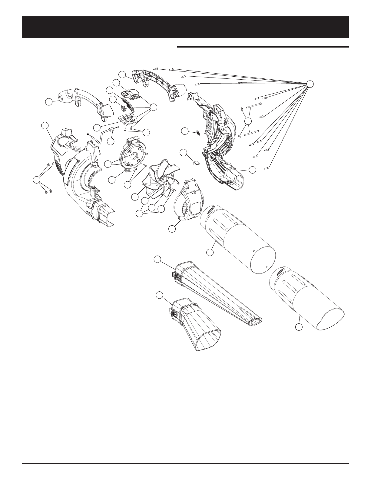
E25
PARTS LIST
HOUSING PARTS - MODEL YM320BV
2-CYCLE GAS MULCHING BLOWER VACUUM
1
5
8
3
10
19
7
11
25
24
26
21
1
22
20
14
3
23
22
Item Part No. Description
1 753-04837 Engine Cover Assm (includes 2)
2 791-181345 Screw
3 753-04451 Handle Assm (includes 2)
4 791-00047 Throttle control Assm (includes 5-7 & 9)
5 791-182420 Upper Throttle Control Plate
6 791-00048 Throttle Control Lever
7 791-182423 Screw
8 791-182405 Rocker Switch Assm
9 791-182422 Lower Throttle Control Plate
10 791-00049 Throttle Cable
11 753-04483 Engine Mount Plate (includes 12 & 13)
12 791-182409 Washer
13 791-181903 Screw
14 753-04596 Impeller Blade
15 753-04482 Impeller Hardware (includes 16-18)
16 753-04833 Washer
17 753-04834 Lock Washer
18 791-182414 Bolt
Item Part No. Description
19 753-04456 Vacuum Door Spring
20 753-04455 Vacuum Door Lock
21 753-04454 Vacuum Door
22 791-182424 Mounting Plate Hardware
23 791-182647 Blower Tube
24 791-182477 Vacuum Bag Adaptor
25 791-180466 Upper Vacuum Tube
26 791-180467 Lower Vacuum Tube
* 791-612930 Cable Tie
* 753-04458 Vacuum Bag Assm
(includes 24, Bag, & Cable Tie)
* 791-682075B Shoulder Strap
* Items Not Shown
6
13
12
18
2
16
9
4
17
15

GARANTÍA LIMITADA DEL FABRICANTE PARA:
Ninguna garantía implícita es aplicable, incluyendo
cualquier garantía implícita de comerciabilidad o
idoneidad para un propósito particular, después del
período de la garantía expresa escrita con anterioridad,
con respecto a las piezas identificadas. Ninguna otra
garantía expresa dada por cualquier persona o entidad,
incluyendo a los distribuidores o minoristas, bien sea
escrita u oral, deberá comprometer a MTD con respecto
a cualquier producto. Durante el período de la Garantía,
la solución exclusiva es arreglar o cambiar el producto
de la manera establecida anteriormente. (Algunos estados
no permiten limitaciones en cuanto al período de duración
de una garantía implícita, de manera que puede que la
limitación anterior no sea aplicable para usted.)
Las estipulaciones establecidas en esta Garantía ofrecen
la solución única y exclusiva que resulte de las ventas.
MTD no deberá ser responsable de pérdidas o daños
incidentales o consecuentes que incluyen, sin limitación,
erogación de gastos debido a la sustitución de servicios
de mantenimiento de prados, transporte o gastos
relacionados, o gastos de alquiler para reemplazar
temporalmente un producto bajo garantía. (Algunos
estados no permiten limitaciones en cuanto al período de
duración de una garantía implícita, de manera que puede
que la limitación anterior no sea aplicable para usted.)
La recuperación de cualquier tipo no deberá ser superior al
precio de compra del producto vendido en ningún caso. La
alteración de las características de seguridad del producto
deberá anular la garantía. Usted asume el riesgo y la
obligación de la pérdida, daño o lesión en su persona o a su
propiedad y / o la de otras personas y sus propiedades, que
se origine a raíz del uso o mal uso, o la falta de capacidad
para usar el producto.
Esta garantía limitada no deberá cubrir a ninguna otra
persona distinta al comprador original, arrendatario original,
o la persona para la que se compró en calidad de regalo.
Relación de las leyes estatales con esta Garantía: Esta
garantía le confiere derechos legales específicos, y puede
que usted también tenga otros derechos, los cuales varían
en cada estado.
Para ubicar a su distribuidor de servicio más cercano, llame
al 1-800-345-8746 en los Estados Unidos a al
1-800-668-1238 en Canadá.
MTD LLC
P.O. Box 361131
Cleveland, OH 44136-0019
La garantía limitada establecida a continuación es dada por
MTD LLC (“MTD”) con respecto a mercancía nueva que sea
comprada y usada en los Estados Unidos, sus posesiones y
territorios.
MTD garantiza este producto contra defectos en el material y
la mano de obra durante un período de dos (2) años, a partir de
la fecha de compra original y a su entera opción, arreglará o
substituirá, sin costo alguno, cualquier pieza cuyo material o
mano de obra se considere defectuoso. Esta garantía limitada
se deberá aplicar únicamente si este producto ha sido
manejado y mantenido de acuerdo al Manual del Operador
incluido con el producto y, si no ha sido sometido a mal uso,
abuso, uso comercial, accidente, mantenimiento inapropiado,
alteración, vandalismo, hurto, fuego, agua o daños debidos a
otros riesgos o desastre natural. Los daños ocasionados por la
instalación o el uso de cualquier accesorio o aditamento que
no esté aprobado por MTD para que sea usado con el (los)
producto(s) contemplados en este manual, anularán la garantía
con respecto a cualquier daño resultante. Esta garantía está
limitada a noventa (90) días a partir de la fecha de compra
original de cualquier producto MTD que se use para alquiler o
para propósitos comerciales, o cualquier otro propósito que
genere ingreso.
CÓMO OBTENER SERVICIO: El servicio de garantía se
encuentra disponible A TRAVÉS DE SU DISTRIBUIDOR
LOCAL AUTORIZADO, AL PRESENTAR UN COMPROBANTE
DE COMPRA. Para ubicar al distribuidor de su área, por favor
consulte las Páginas Amarillas o contacte al Departamento de
Servicio al Consumidor de MTD LLC llame al 1-800-345-8746
o, escriba a P.O. Box 361131, Cleveland OH 44136-0019. Si
está en Canadá, llame al 1-800-668-1238. No se aceptará
ningún producto que sea enviado directamente a la fábrica, a
menos que haya recibido autorización previa por escrito por
parte del Departamento de Servicio al Consumidor de MTD
LLC.
Esta garantía limitada no ofrece cobertura en los
siguientes casos:
A. Sincronizaciones — Bujías, ajustes de carburadores,
filtros.
B. Artículos de desgaste — Botón de tope, carretes
externos, línea de corte, carretes internos, polea de
arranque, cuerdas de arranque, correas motoras.
C. MTD no le ofrece ninguna garantía a productos que sean
vendidos o exportados fuera de los Estados Unidos de
Norteamérica, sus posesiones y territorios, excepto
aquellos que se vendan a través de los canales de
distribución para exportación autorizados por MTD.
MTD se reserva el derecho a cambiar o mejorar el diseño de
cualquier producto MTD, sin asumir ninguna obligación para
modificar ningún producto fabricado con anterioridad.
 Loading...