

Yamaha MTN320-A User Manual
Read this manual carefully before operating this vehicle.
OWNER’S MANUAL
MTN320-A
B08-F8199-E1

EAU46091
Read this manual carefully before operating this vehicle. This manual should stay with this vehicle if it is sold.

Introduction
WARNING
EAU10103
Welcome to the Yamaha world of motorcycling!
As the owner of the MTN320-A, you are benefiting from Yamaha’s vast experience and newest technology regarding the
design and manufacture of high-quality products, which have earned Yamaha a reputation for dependability.
Please take the time to read this manual thoroughly, so as to enjoy all advantages of your MTN320-A. The Owner’s Manual
does not only instruct you in how to operate, inspect and maintain your motorcycle, but also in how to safeguard yourself
and others from trouble and injury.
In addition, the many tips given in this manual will help keep your motorcycle in the best possible condition. If you have any
further questions, do not hesitate to contact your Yamaha dealer.
The Yamaha team wishes you many safe and pleasant rides. So, remember to put safety first!
Yamaha continually seeks advancements in product design and quality. Therefore, while this manual contains the most current product information available at the time of printing, there may be minor discrepancies between your motorcycle and
this manual. If there is any question concerning this manual, please consult a Yamaha dealer.
Please read this manual carefully and completely before operating this motorcycle.
EWA10032
Important manual information
WARNING
NOTICE
TIP
Particularly important information is distinguished in this manual by the following notations:
This is the safety alert symbol. It is used to alert you to potential personal injury
hazards. Obey all safety messages that follow this symbol to avoid possible injury
or death.
A WARNING indicates a hazardous situation which, if not avoided, could result in
death or serious injury.
A NOTICE ind icates special precautions that must be taken to avoid damage to the
vehicle or other property.
A TIP provides key information to make procedures easier or clearer.
*Product and specifications are subject to change without notice.
EAU10134

Important manual information
EAUN0430
MTN320-A
OWNER’S MANUAL
©2015 PT Yamaha Indonesia Motor
Manufacturing
1st edition, November 2015
All rights reserved.
Any reprinting or unauthorized use
without the written permission of
PT Yamaha Indonesia Motor Manufac-
turing
is expressly prohibited.
Printed in Indonesia.

Table of contents
Safety information............................ 1-1
Description ....................................... 2-1
Left view ......................................... 2-1
Right view....................................... 2-2
Controls and instruments............... 2-3
Instrument and control functions... 3-1
Main switch/steering lock............... 3-1
Indicator lights and warning
lights............................................ 3-2
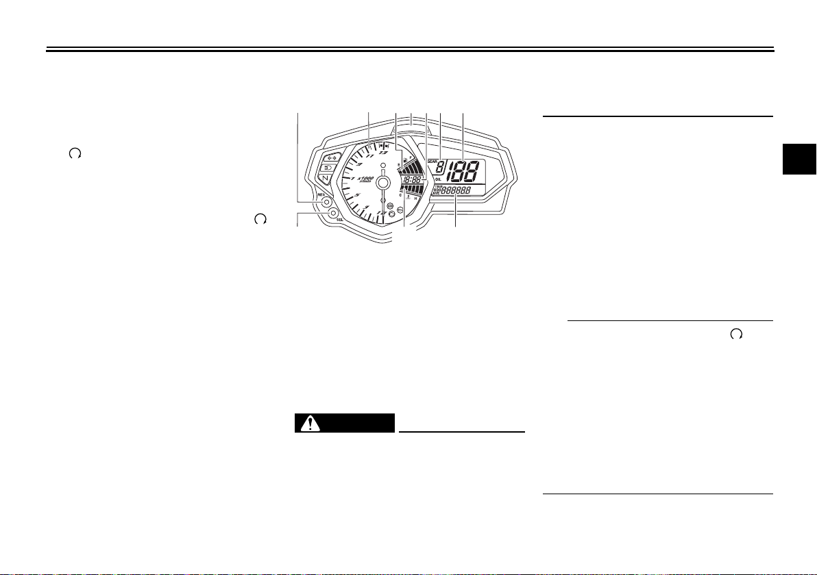
Multi-function meter unit ................ 3-4
Handlebar switches...................... 3-11
Clutch lever .................................. 3-12
Shift pedal .................................... 3-13
Brake lever.................................... 3-13
Brake pedal .................................. 3-13
ABS .............................................. 3-14
Fuel tank cap................................ 3-15
Fuel............................................... 3-15
Fuel tank breather hose and
overflow hose............................ 3-17
Catalytic converter ....................... 3-17
Seats ............................................ 3-18
Helmet holders ............................. 3-19
Storage compartment .................. 3-20
Adjusting the shock absorber
assembly................................... 3-20
Luggage strap holders ................. 3-21
Sidestand ..................................... 3-21
Ignition circuit cut-off system....... 3-22
For your safety – pre-operation
checks ...............................................4-1
Operation and important riding
points .................................................5-1
Starting the engine..........................5-1
Shifting............................................5-2
Engine break-in...............................5-4
Parking............................................5-4
Periodic maintenance and
adjustment ........................................6-1
Owner’s tool kit...............................6-2
Periodic maintenance chart for
the emission control system........ 6-3
General maintenance and
lubrication chart...........................6-4
Checking the spark plugs ............... 6-8
Engine oil and oil filter cartridge......6-9
Coolant..........................................6-12
Replacing the air filter element
and cleaning the check hose.....6-13
Checking the throttle grip
free play.....................................6-15
Valve clearance.............................6-15
Tires ..............................................6-15
Cast wheels...................................6-17
Adjusting the clutch lever
free play.....................................6-17
Checking the brake lever
free play.....................................6-18
Brake light switches ..................... 6-19
Checking the front and rear
brake pads ................................ 6-19
Checking the brake fluid level ...... 6-20
Changing the brake fluid .............. 6-21
Drive chain slack........................... 6-21
Cleaning and lubricating the
drive chain................................. 6-23
Checking and lubricating the
cables........................................ 6-24
Checking and lubricating the
throttle grip and cable............... 6-24
Checking and lubricating the
brake and shift pedals............... 6-24
Checking and lubricating the
brake and clutch levers............. 6-25
Checking and lubricating the
sidestand................................... 6-26
Lubricating the swingarm
pivots......................................... 6-26
Checking the front fork................. 6-26
Checking the steering................... 6-27
Checking the wheel bearings ....... 6-27
Battery .......................................... 6-28
Replacing the fuses ...................... 6-29
Replacing the headlight bulb........ 6-31
Auxiliary light ................................ 6-31
Tail/brake light .............................. 6-32
Replacing a turn signal light
bulb ........................................... 6-32

Replacing the license plate
light bulb ....................................6-33
Supporting the motorcycle............6-34
Troubleshooting ............................6-34
Troubleshooting charts .................6-36
Motorcycle care and storage ..........7-1
Matte color caution .........................7-1
Care.................................................7-1
Storage............................................7-4
Specifications....................................8-1
Consumer information .....................9-1
Identification numbers.....................9-1
Index ................................................10-1
Table of contents

Safety information
1
Be a Responsible Owner
As the vehicle’s owner, you are responsible for the safe and proper operation of your motorcycle.
Motorcycles are single-track vehicles.
Their safe use and operation are dependent upon the use of proper riding
techniques as well as the expertise of
the operator. Every operator should
know the following requirements before riding this motorcycle.
He or she should:
Obtain thorough instructions from
a competent source on all aspects
of motorcycle operation.
Observe the warnings and mainte-
nance requirements in this Own-
er’s Manual.
Obtain qualified training in safe
and proper riding techniques.
Obtain professional technical ser-
vice as indicated in this Owner’s
Manual and/or when made neces-
sary by mechanical conditions.
EAU1028B
Never operate a motorcycle with-
out proper training or instruction.
Take a training course. Beginners
should receive training from a certified instructor. Contact an authorized motorcycle dealer to find out
about the training courses nearest
you.
Safe Riding
Perform the pre-operation checks
each time you use the vehicle to make
sure it is in safe operating condition.
Failure to inspect or maintain the vehicle properly increases the possibility of
an accident or equipment damage.
See page 4-1 for a list of pre-operation
checks.
This motorcycle is designed to
carry the operator and a passenger.
The failure of motorists to detect
and recognize motorcycles in traffic is the predominating cause of
automobile/motorcycle accidents.
Many accidents have been
caused by an automobile driver
who did not see the motorcycle.
Making yourself conspicuous ap-
1-1
pears to be very effective in reducing the chance of this type of
accident.
Therefore:
• Wear a brightly colored jacket.
• Use extra caution when you are
approaching and passing
through intersections, since intersections are the most likely
places for motorcycle accidents
to occur.
• Ride where other motorists can
see you. Avoid riding in another
motorist’s blind spot.
• Never maintain a motorcycle
without proper knowledge.
Contact an authorized motorcycle dealer to inform you on basic motorcycle maintenance.
Certain maintenance can only
be carried out by certified staff.

Safety information
Many accidents involve inexperi-
enced operators. In fact, many operators who have been involved in
accidents do not even have a current motorcycle license.
• Make sure that you are qualified
and that you only lend your motorcycle to other qualified operators.
• Know your skills and limits.
Staying within your limits may
help you to avoid an accident.
• We recommend that you practice riding your motorcycle
where there is no traffic until you
have become thoroughly familiar with the motorcycle and all of
its controls.
Many accidents have been
caused by error of the motorcycle
operator. A typical error made by
the operator is veering wide on a
turn due to excessive speed or undercornering (insufficient lean angle for the speed).
• Always obey the speed limit and
never travel faster than warranted by road and traffic conditions.
• Always signal before turning or
changing lanes. Make sure that
other motorists can see you.
The posture of the operator and
passenger is important for proper
control.
• The operator should keep both
hands on the handlebar and
both feet on the operator footrests during operation to maintain control of the motorcycle.
• The passenger should always
hold onto the operator, the seat
strap or grab bar, if equipped,
with both hands and keep both
feet on the passenger footrests.
Never carry a passenger unless
he or she can firmly place both
feet on the passenger footrests.
Never ride under the influence of
alcohol or other drugs.
This motorcycle is designed for
on-road use only. It is not suitable
for off-road use.
1-2
Protective Apparel
The majority of fatalities from motorcycle accidents are the result of head injuries. The use of a safety helmet is the
single most critical factor in the prevention or reduction of head injuries.
Always wear an approved helmet.
Wear a face shield or goggles.
Wind in your unprotected eyes
could contribute to an impairment
of vision that could delay seeing a
hazard.
The use of a jacket, heavy boots,
trousers, gloves, etc., is effective
in preventing or reducing abrasions or lacerations.
Never wear loose-fitting clothes,
otherwise they could catch on the
control levers, footrests, or wheels
and cause injury or an accident.
Always wear protective clothing
that covers your legs, ankles, and
feet. The engine or exhaust system become very hot during or after operation and can cause
burns.
A passenger should also observe
the above precautions.
1
Safety information
Avoid Carbon Monoxide Poisoning
1
All engine exhaust contains carbon
monoxide, a deadly gas. Breathing
carbon monoxide can cause headaches, dizziness, drowsiness, nausea,
confusion, and eventually death.
Carbon Monoxide is a colorless, odorless, tasteless gas which may be
present even if you do not see or smell
any engine exhaust. Deadly levels of
carbon monoxide can collect rapidly
and you can quickly be overcome and
unable to save yourself. Also, deadly
levels of carbon monoxide can linger
for hours or days in enclosed or poorly
ventilated areas. If you experience any
symptoms of carbon monoxide poisoning, leave the area immediately, get
fresh air, and SEEK MEDICAL TREATMENT.
Do not run engine indoors. Even if
you try to ventilate engine exhaust
with fans or open windows and
doors, carbon monoxide can rapidly reach dangerous levels.
Do not run engine in poorly venti-
lated or partially enclosed areas
such as barns, garages, or carports.
Do not run engine outdoors where
engine exhaust can be drawn into
a building through openings such
as windows and doors.
Loading
Adding accessories or cargo to your
motorcycle can adversely affect stability and handling if the weight distribution of the motorcycle is changed. To
avoid the possibility of an accident, use
extreme caution when adding cargo or
accessories to your motorcycle. Use
extra care when riding a motorcycle
that has added cargo or accessories.
Here, along with the information about
accessories below, are some general
guidelines to follow if loading cargo to
your motorcycle:
The total weight of the operator, passenger, accessories and cargo must
not exceed the maximum load limit.
Operation of an overloaded vehicle
could cause an accident.
Maximum load:
160 kg (353 lb)
1-3
When loading within this weight limit,
keep the following in mind:
Cargo and accessory weight
should be kept as low and close to
the motorcycle as possible. Securely pack your heaviest items as
close to the center of the vehicle
as possible and make sure to distribute the weight as evenly as
possible on both sides of the motorcycle to minimize imbalance or
instability.
Shifting weights can create a sud-
den imbalance. Make sure that
accessories and cargo are securely attached to the motorcycle
before riding. Check accessory
mounts and cargo restraints frequently.
• Properly adjust the suspension
for your load (suspension-adjustable models only), and
check the condition and pressure of your tires.
• Never attach any large or heavy
items to the handlebar, front
fork, or front fender. These
items, including such cargo as
sleeping bags, duffel bags, or

Safety information
tents, can create unstable handling or a slow steering response.
This vehicle is not designed to
pull a trailer or to be attached to
a sidecar.
Genuine Yamaha Accessories
Choosing accessories for your vehicle
is an important decision. Genuine
Yamaha accessories, which are available only from a Yamaha dealer, have
been designed, tested, and approved
by Yamaha for use on your vehicle.
Many companies with no connection
to Yamaha manufacture parts and accessories or offer other modifications
for Yamaha vehicles. Yamaha is not in
a position to test the products that
these aftermarket companies produce.
Therefore, Yamaha can neither endorse nor recommend the use of accessories not sold by Yamaha or
modifications not specifically recommended by Yamaha, even if sold and
installed by a Yamaha dealer.
Aftermarket Parts, Accessories, and
Modifications
While you may find aftermarket products similar in design and quality to
genuine Yamaha accessories, recognize that some aftermarket accessories or modifications are not suitable
because of potential safety hazards to
you or others. Installing aftermarket
products or having other modifications
performed to your vehicle that change
any of the vehicle’s design or operation
characteristics can put you and others
at greater risk of serious injury or
death. You are responsible for injuries
related to changes in the vehicle.
Keep the following guidelines in mind,
as well as those provided under “Loading” when mounting accessories.
Never install accessories or carry
cargo that would impair the performance of your motorcycle.
Carefully inspect the accessory
before using it to make sure that it
does not in any way reduce
ground clearance or cornering
clearance, limit suspension travel,
steering travel or control operation, or obscure lights or reflectors.
• Accessories fitted to the handlebar or the front fork area can
create instability due to improper weight distribution or aerodynamic changes. If accessories
are added to the handlebar or
front fork area, they must be as
lightweight as possible and
should be kept to a minimum.
• Bulky or large accessories may
seriously affect the stability of
the motorcycle due to aerodynamic effects. Wind may attempt to lift the motorcycle, or
the motorcycle may become
unstable in cross winds. These
accessories may also cause instability when passing or being
passed by large vehicles.
• Certain accessories can displace the operator from his or
her normal riding position. This
improper position limits the
freedom of movement of the
1
1-4

Safety information
1
operator and may limit control
ability, therefore, such accessories are not recommended.
Use caution when adding electri-
cal accessories. If electrical accessories exceed the capacity of
the motorcycle’s electrical system, an electric failure could result, which could cause a
dangerous loss of lights or engine
power.
Aftermarket Tires and Rims
The tires and rims that came with your
motorcycle were designed to match
the performance capabilities and to
provide the best combination of handling, braking, and comfort. Other
tires, rims, sizes, and combinations
may not be appropriate. Refer to page
6-15 for tire specifications and more information on replacing your tires.
Transporting the Motorcycle
Be sure to observe following instructions before transporting the motorcycle in another vehicle.
Remove all loose items from the
motorcycle.
Check that the fuel cock (if
equipped) is in the “OFF” position
and that there are no fuel leaks.
Point the front wheel straight
ahead on the trailer or in the truck
bed, and choke it in a rail to prevent movement.
Shift the transmission in gear (for
models with a manual transmission).
Secure the motorcycle with tie-
downs or suitable straps that are
attached to solid parts of the motorcycle, such as the frame or upper front fork triple clamp (and not,
for example, to rubber-mounted
handlebars or turn signals, or
parts that could break). Choose
the location for the straps carefully
so the straps will not rub against
painted surfaces during transport.
The suspension should be com-
pressed somewhat by the tiedowns, if possible, so that the motorcycle will not bounce excessively during transport.
1-5
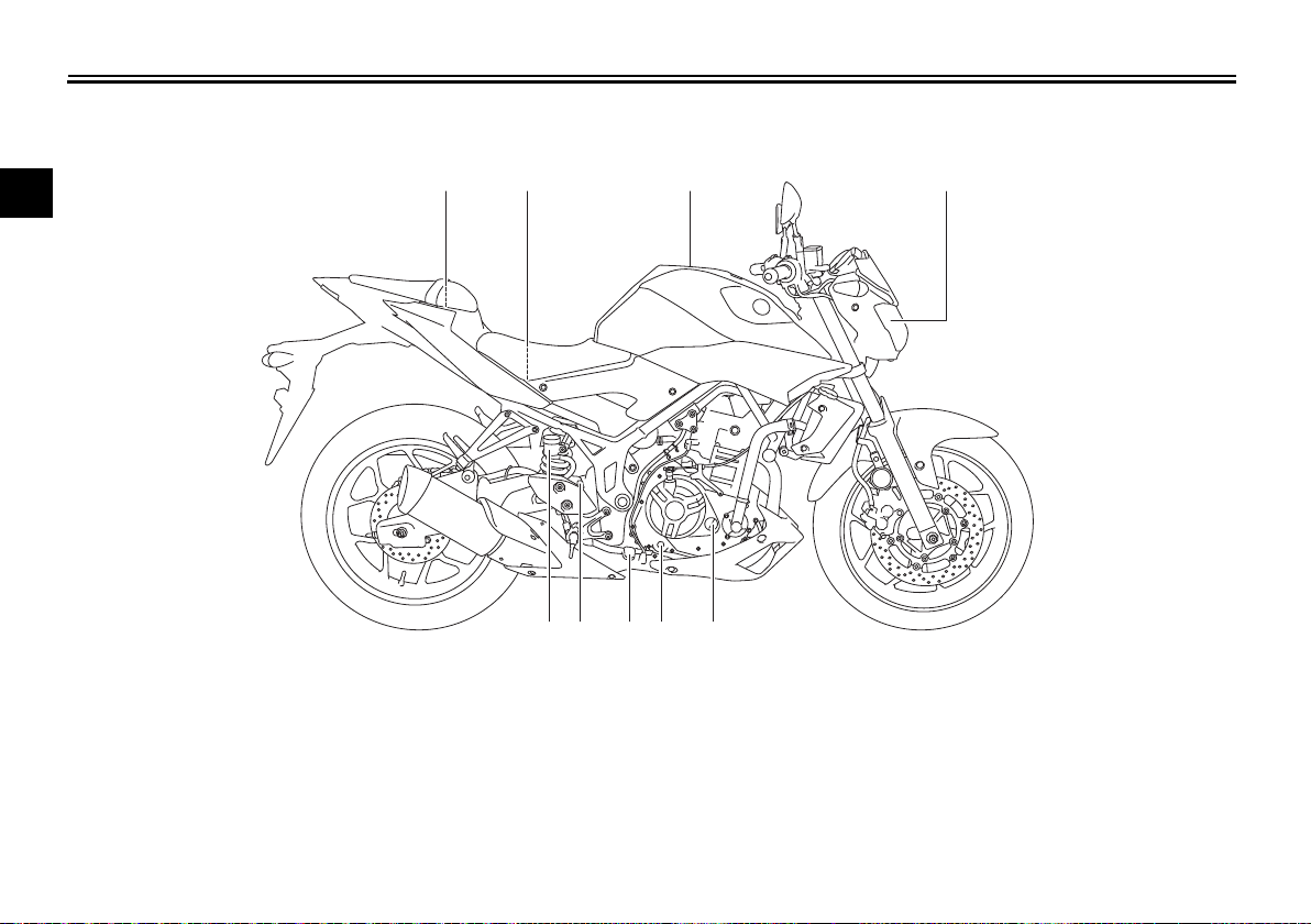
Left view
1
76
2345
98
Description
EAU10411
2
1. Coolant reservoir (page 6-12)
2. Main fuse (page 6-29)
3. Owner’s tool kit (page 6-2)
4. Passenger seat lock (page 3-18)
5. Storage compartment (page 3-20)
6. Shock absorber assembly spring preload adjusting ring (page 3-20)
7. Shift pedal (page 3-13)
8. Engine oil drain bolt (page 6-9)
9. Engine oil filter cartridge (page 6-9)
2-1
Description
Right view
EAU10421
2
1. Fuse box (page 6-29)
2. Battery (page 6-28)
3. Fuel tank cap (page 3-15)
4. Headlight (page 6-31)
5. Engine oil filler cap (page 6-9)
6. Engine oil level check window (page 6-9)
7. Brake pedal (page 3-13)
8. Rear brake light switch (page 6-19)
1
23 4
98 76 5
9. Rear brake fluid reservoir (page 6-20)
2-2
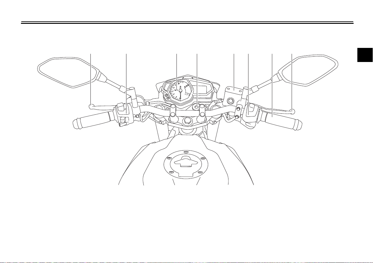
Controls and instruments
1 2 3 4 5 6 7 8
1. Clutch lever (page 3-12)
2. Left handlebar switches (page 3-11)
3. Multi-function meter unit (page 3-4)
4. Main switch/steering lock (page 3-1)
5. Front brake fluid reservoir (page 6-20)
6. Right handlebar switches (page 3-11)
7. Throttle grip (page 6-15)
8. Brake lever (page 3-13)
Description
EAU10431
2
2-3
Instrument and control functions
TIP
WARNING
TIP
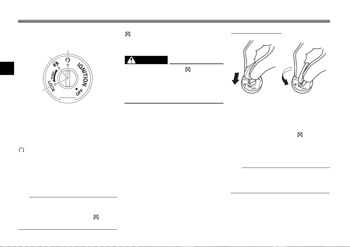
ON
OFF
LOCK
12
Main switch/steering lock
3
The main switch/steering lock controls
the ignition and lighting systems, and is
used to lock the steering. The various
positions are described below.
(on)
All electrical circuits are supplied with
power; the meter lighting, taillight, license plate light and auxiliary light
come on, and the engine can be started. The key cannot be removed.
The headlight comes on automatically
when the engine is started and stays
on until the key is turned to “ ”, even
if the engine stalls.
EAU10462
EAU62480
(off)
EAU54301
All electrical systems are off. The key
can be removed.
EWA16371
Never turn the key to “ ” or “LOCK”
while the vehicle is moving. Otherwise the electrical systems will be
switched off, which may result in
loss of control or an accident.
EAU60861
LOCK
The steering is locked and all electrical
systems are off. The key can be removed.
3-1
To lock the steering
1. Push.
2. Turn.
1. Turn the handlebars all the way to
the left.
2. With the key in the “ ” position,
push the key in and turn it to
“LOCK”.
3. Remove the key.
If the steering will not lock, try turning
the handlebars back to the right slightly.
Instrument and control functions
NOTICE
12
5
6
3
2
4
km/h
km/L
L/100km
7
MPH
mileMPG
ABS
To unlock the steering
1. Push.
2. Turn.
1. Insert the key.
2. With the key in the “LOCK” position, push the key in and turn it
to “ ”.
EAU49398
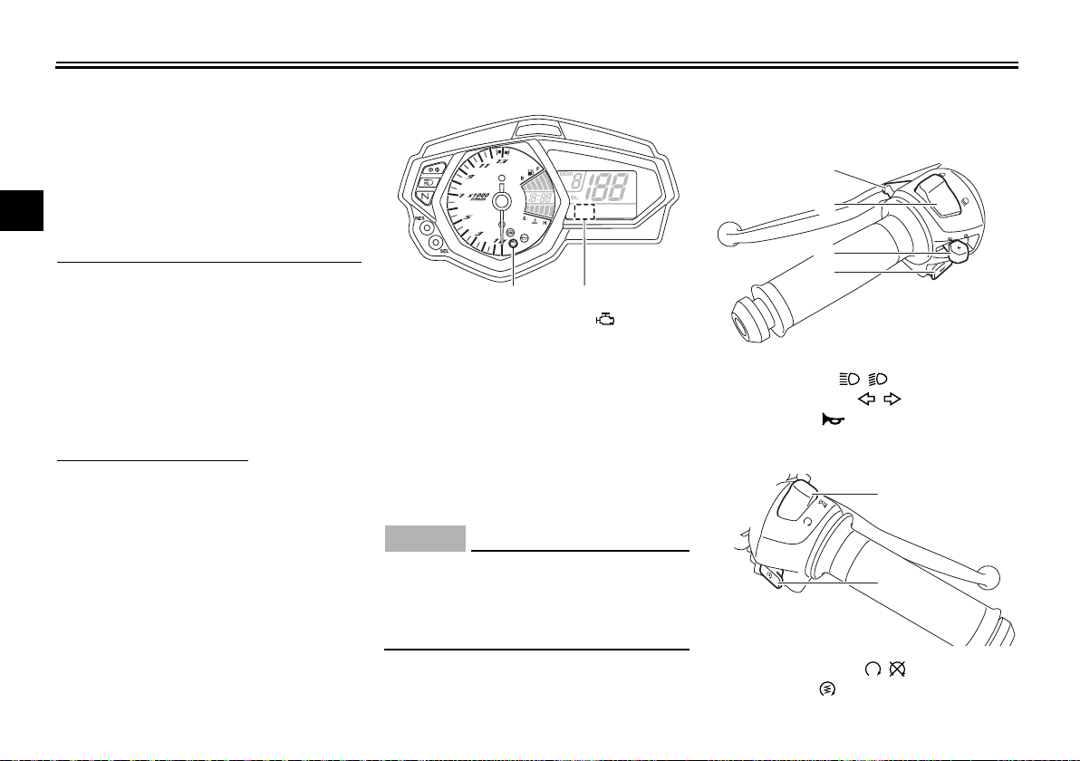
Indicator lights and warning lights
1. Neutral indicator light “ ”
2. High beam indicator light “ ”
3. Turn signal indicator light “ ”
4. Shift timing indicator light
5. Engine trouble warning light “ ”
6. Oil pressure warning light “ ”
7. Anti-lock Brake System (ABS) warning
light “ ”
EAU11022
Turn signal indicator light “ ”
This indicator light flashes when a turn
signal light is flashing.
EAU11061
Neutral indicator light “ ”
This indicator light comes on when the
transmission is in the neutral position.
High beam indicator light “ ”
EAU11081
This indicator light comes on when the
high beam of the headlight is switched
on.
EAU62530
Oil pressure warning light “ ”
This warning light comes on if the engine oil pressure is low.
The electrical circuit of the warning
light can be checked by turning the key
to “ ”. The warning light should come
on and remain on until the engine is
started.
If the warning light does not come on
initially when the key is turned to “ ”,
have a Yamaha dealer check the electrical circuit.
ECA21210
If the warning light comes on when
the engine is running, stop the en-
gine immediately and check oil level.
If the oil level is below the minimum
level, add sufficient oil of the recommended type to r aise it up to t h e correct level. If the oil pressure warning
light remains on even if the oil level
3
3-2
Instrument and control functions
TIP
TIP
WARNING
TIP
ABS
3
is correct, immediately turn the engine off and have a Yamaha dealer
check the vehicle.
If the warning light does not go off after
starting the engine, check the engine
oil level and add oil if necessary. (See
page 6-9.)
If the warning light remains on after
adding engine oil, have a Yamaha
dealer check the vehicle.
Engine trouble warning light “ ”
This warning light comes on or flashes
if a problem is detected in the electrical
circuit monitoring the engine. If this occurs, have a Yamaha dealer check the
self-diagnosis system. (See page 3-11
for an explanation of the self-diagnosis
device.)
The electrical circuit of the warning
light can be checked by turning the key
to “ ”. The warning light should come
on for a few seconds, and then go off.
EAU62790
If the warning light does not come on
initially when the key is turned to “ ”,
or if the warning light remains on, have
a Yamaha dealer check the electrical
circuit.
The engine trouble warning light will
come on while the start switch is
pushed, but this does not indicate a
malfunction.
EAU51662
ABS warning light “ ”
In normal operation, the ABS warning
light comes on when the key is turned
to “ON”, and goes off after traveling at
a speed of 10 km/h (6 mi/h) or higher.
If the ABS warning light:
does not come on when the key is
turned to “ON”
comes on or flashes while riding
does not go off after traveling at a
speed of 10 km/h (6 mi/h) or high-
er
The ABS may not work correctly. If any
of the above occurs, have a Yamaha
dealer check the system as soon as
possible. (See page 3-14 for an explanation of the ABS.)
3-3
EWA16041
If the ABS warning light does not go
off after traveling at a speed of 10
km/h (6 mi/h) or higher, or if the
warning light comes on or flashes
while riding, the brake system reverts to conventional braking. If either of the above occurs, or if the
warning light does not come on at
all, use extra caution to avoid possi-
ble wheel lock during emergency
braking. Have a Yamaha dealer
check the brake system and electrical circuits as soon as possible.
If the start switch is pushed while the
engine is running, the ABS warning
light will come on, but this is not a malfunction.
EAU62470
Shift timing indicator light
This indicator light can be set to come
on and go off at the desired engine
speeds and is used to inform the rider
when it is time to shift to the next high-
Instrument and control functions
WARNING
TIP
10
9
3
4
6
5
7
8
km/h
km/L
L/100km
MPH
mileMPG
er gear. (See page 3-9 for a more detailed explanation of this indicator light
and on how to set it.)
The electrical circuit of the indicator
light can be checked by turning the key
to “ ”. The indicator light should
come on for a few seconds, and then
go off.
If the indicator light does not come on
initially when the key is turned to “ ”,
or if the indicator light remains on, have
a Yamaha dealer check the electrical
circuit.
EAUN0871
Multi-function meter unit
1. “SEL” button
2. “RES” button
3. Tachometer
4. Fuel meter
5. Shift timing indicator light
6. Clock
7. Transmission gear display
8. Speedometer
9. Multi-function display
10.Coolant temperature meter
EWA12423
Be sure to stop the vehicle before
making any setting changes to the
multi-function meter unit. Changing
settings while riding can distract the
operator and increase the risk of an
accident.
The multi-function meter unit is
equipped with the following:
a speedometer
a tachometer
a clock
a fuel meter
a coolant temperature meter
a transmission gear display
a multi-function display
a shift timing indicator light
a self-diagnosis device
Be sure to turn the key to “ ” be-
fore using the “SEL” and “RES”
buttons, except for setting the
shift timing indicator light control
mode.
For the UK only: To switch the
speedometer and multi-function
displays between kilometers and
miles, press the “SEL” button for
at least one second.
3
3-4
Instrument and control functions
NOTICE
2
1
km/h
km/L
L/100km
MPH
mileMPG
1
1
Speedometer
The speedometer shows the vehicle’s
traveling speed.
Tachometer
3
1. Tachometer
2. Tachometer red zone
The tachometer allows the rider to
monitor the engine speed and keep it
within the ideal power range.
When the key is turned to “ ”, the tachometer will sweep across the r/min
range and then return to zero r/min in
order to test the electrical circuit.
Do not operate the engine in the tachometer red zone.
ECA10032
Red zone: 12500 r/min and above
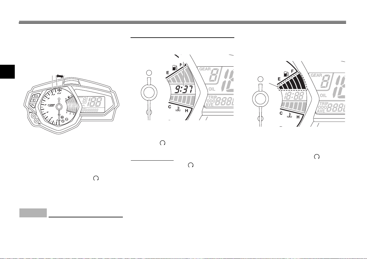
Clock
1. Clock
The clock is displayed when the key is
turned to “ ”.
To set the clock
1. Turn the key to “ ”.
2. Push the “SEL” button and “RES”
button together for at least two
seconds.
3. When the hour digits start flashing, push the “RES” button to set
the hours.
4. Push the “SEL” button, and the
minute digits will start flashing.
5. Push the “RES” button to set the
minutes.
3-5
6. Push the “SEL” button and then
release it to start the clock.
Fuel meter
1. Fuel meter
The fuel meter indicates the amount of
fuel in the fuel tank.
When the key is turned to “ ”, the display segments of the fuel meter will
sweep once across the fuel level range
and then return to the current amount
in order to test the electrical circuit.
The display segments of the fuel meter
disappear towards “E” (Empty) as the
fuel level decreases. When the last
segment starts flashing, refuel as soon
as possible.
Instrument and control functions
TIP
NOTICE
TIP
1
1
2
MPH
km/h
km
1
This fuel meter is equipped with a selfdiagnosis system. If a problem is detected in the electrical circuit, the following cycle is repeated until the
malfunction is corrected: fuel level segments flash eight times, then go off for
approximately three seconds. If this
occurs, have a Yamaha dealer check
the electrical circuit.
Coolant temperature meter
1. Coolant temperature meter
The coolant temperature meter indicates the temperature of the coolant.
When the key is turned to “ ”, the display segments of the digital coolant
temperature meter will sweep once
across the temperature range and then
return to “C” in order to test the electrical circuit.
If the last segment on the right flashes,
stop the vehicle, then stop the engine,
and let the engine cool. (See page
6-37.)
ECA10022
Do not continue to operate the engine if it is overheating.
The coolant temperature varies with
changes in the weather and engine
load.
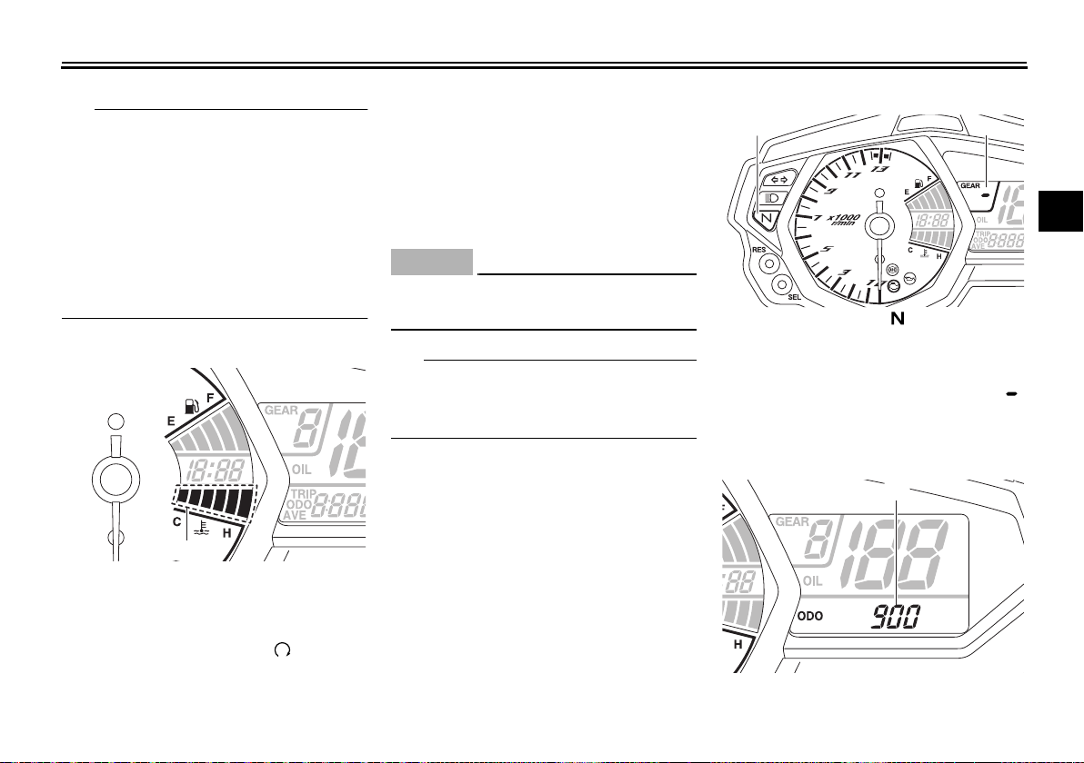
Transmission gear display
3
1. Neutral indicator light “ ”
2. Transmission gear display
This display shows the selected gear.
The neutral position is indicated by “ ”
and by the neutral indicator light.
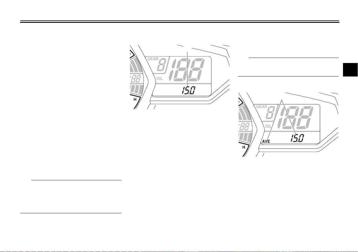
Multi-function display
1. Multi-function display
3-6

Instrument and control functions
The multi-function display is equipped
with the following:
an odometer
two tripmeters
a fuel reserve tripmeter
an instantaneous fuel consump-
3
tion display
an average fuel consumption dis-
play
an oil change tripmeter
an oil change indicator
The odometer shows the total distance
traveled by the vehicle.
The tripmeters show the distance traveled since they were last set to zero.
The fuel reserve tripmeter shows the
distance traveled since the fuel level
warning light came on.
Except for the UK:
Push the “SEL” button to switch the
display between the odometer mode
“ODO”, tripmeter modes “TRIP 1” and
“TRIP 2”, instantaneous fuel consumption mode “L/100 km” or “km/L”, average fuel consumption mode “AVE_ _._
L/100 km” or “AVE_ _._ km/L” and oil
change tripmeter mode “OIL TRIP” in
the following order:
ODO → TRIP 1 → TRIP 2 → L/100 km
or km/L → AVE_ _._ L/100 km or AVE_
_._ km/L → OIL TRIP → ODO
If the left segment of the fuel meter
starts flashing, the display automatically changes to the fuel reserve tripmeter mode “TRIP F” and starts
counting the distance traveled from
that point. In that case, push the “SEL”
button to switch the display between
the various tripmeter, odometer, instantaneous fuel consumption and average fuel consumption modes in the
following order:
TRIP F → L/100 km or km/L → AVE_
_._ L/100 km or AVE_ _._ km/L → OIL
TRIP → ODO → TRIP 1 → TRIP 2 →
TRIP F
To reset a tripmeter, select it by pushing the “SEL” button, and then push
the “RES” button for at least one second.
3-7
If you do not reset the fuel reserve tripmeter manually, it resets itself automatically and the display returns to the
prior mode after refueling and traveling
5 km (3 mi).
For the UK only:
Push the “SEL” button to switch the
display between the odometer mode
“ODO”, tripmeter modes “TRIP 1” and
“TRIP 2”, instantaneous fuel consumption mode “MPG”, “L/100 km” or
“km/L”, average fuel consumption
mode “AVE_ _._ MPG”, “AVE_ _._
L/100 km” or “AVE_ _._ km/L” and oil
change tripmeter mode “OIL TRIP” in
the following order:
ODO → TRIP 1 → TRIP 2 → MPG,
L/100 km or km/L → AVE_ _._ MPG,
AVE_ _._ L/100 km or AVE_ _._ km/L →
OIL TRIP → ODO
If the left segment of the fuel meter
starts flashing, the display automatically changes to the fuel reserve tripmeter mode “TRIP F” and starts
counting the distance traveled from
Instrument and control functions
TIP
TIP
MPH
km/h
km/L
1
MPH
km/h
km/L
1
that point. In that case, push the “SEL”
button to switch the display between
the various tripmeter, odometer, instantaneous fuel consumption and average fuel consumption modes in the
following order:
TRIP F → MPG, L/100 km or km/L →
AVE_ _._ MPG, AVE_ _._ L/100 km or
AVE_ _._ km/L → OIL TRIP → ODO →
TRIP 1 → TRIP 2 → TRIP F
To reset a tripmeter, select it by pushing the “SEL” button, and then push
the “RES” button for at least one second.
If you do not reset the fuel reserve tripmeter manually, it resets itself automatically and the display returns to the
prior mode after refueling and traveling
5 km (3 mi).
The odometer will lock at 999999.
The tripmeters will reset and con-
tinue counting after 9999.9 is
reached.
Instantaneous fuel consumption
display
1. Instantaneous fuel consumption display
The instantaneous fuel consumption
display can be set to either “L/100 km”,
“km/L” or “MPG” (for the UK only).
“L/100 km”: The amount of fuel
necessary to travel 100 km under
the current riding conditions is
shown.
“km/L”: The distance that can be
traveled on 1.0 L of fuel under the
current riding conditions is shown.
“MPG” (for the UK only): The dis-
tance that can be traveled on 1.0
Imp. gal of fuel under the current
riding conditions is shown.
To switch between the instantaneous
fuel consumption displays, push the
“SEL” button for one second.
If traveling at speeds under 20 km/h
(12 mi/h), “_ _._” is displayed.
Average fuel consumption display
1. Average fuel consumption display
The average fuel consumption display
can be set to either “AVE_ _._ L/100
km”, “AVE_ _._ km/L” or “AVE_ _._
MPG” (for the UK only).
This display shows the average fuel
consumption since it was last reset.
“AVE_ _._ L/100 km”: The average
amount of fuel necessary to travel
100 km is shown.
3
3-8
Instrument and control functions
TIP
MPH
km/h
km
21
1
2
km/h
MPH
“AVE_ _._ km/L”: The average dis-
tance that can be traveled on 1.0 L
of fuel is shown.
“AVE_ _._ MPG” (for the UK only):
The average distance that can be
3
traveled on 1.0 Imp. gal of fuel is
shown.
To switch between the average fuel
consumption displays, push the “SEL”
button for one second.
To reset the average fuel consumption
display, push the “RES” button for at
least one second.
After resetting the average fuel consumption display, “_ _._” is shown until
the vehicle has traveled 1 km (0.6 mi).
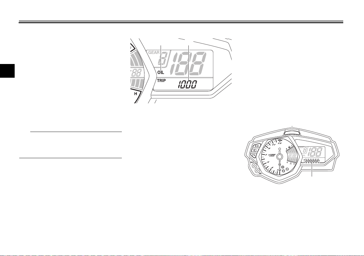
Oil change tripmeter
1. Oil change indicator “OIL”
2. Oil change tripmeter
The oil change tripmeter shows the
distance traveled since it was last reset
(i.e., since the last oil change).
The oil change indicator “OIL” will flash
at the initial 1000 km (600 mi), then at
5000 km (3000 mi) and every 5000 km
(3000 mi) thereafter to indicate that the
engine oil should be changed.
After changing the engine oil, reset the
oil change tripmeter and the oil change
indicator. To reset them both, select
the oil change tripmeter, and then push
the “RES” button for one second.
Then, while “OIL” and the oil change
tripmeter are flashing, push the “RES”
button for three seconds. The oil
change indicator will be reset.
If the engine oil is changed before the
oil change indicator comes on (i.e., before the periodic oil change interval has
been reached), the oil change tripmeter
must be reset for the next periodic oil
change to be indicated at the correct
time.
Shift timing indicator light
1. Shift timing indicator light
2. Brightness level display
The shift timing indicator light has four
settings which can be adjusted.
3-9

Instrument and control functions
TIP
TIP
Flashing pattern: this function al-
lows you to choose whether or not
the indicator light will come on and
whether it should flash or stay on
when activated.
Activation point: this function al-
lows you to select the engine
speed at which the indicator light
is activated.
Deactivation point: this function
allows you to select the engine
speed at which the indicator light
is deactivated.
Brightness: this function allows
you to adjust the brightness of the
indicator light.
To adjust the shift timing indicator light
1. Turn the key to “ ”.
2. Push and hold the “SEL” button.
3. Turn the key to “ ”, and then release the “SEL” button after five
seconds. The shift timing indicator
light can now be adjusted.
To set the flashing pattern
1. Push the “RES” button to select
one of the following flashing pattern settings:
On: the indicator light stays
on when activated. (This setting is selected when the indicator light stays on.)
Flash: the indicator light
flashes when activated. (This
setting is selected when the
indicator light flashes four
times per second.)
Off: the indicator light is deac-
tivated; in other words, it
does not come on or flash.
(This setting is selected when
the indicator light flashes
once every two seconds.)
2. Push the “SEL” button to confirm
the selected flashing pattern. The
shift timing indicator light changes
to the activation point setting
mode.
The tachometer will show the current
setting r/min for the activation point
and deactivation point setting modes.
3-10
To set the shift activation point
The shift timing indicator light activation point can be set between 7000
r/min and 13500 r/min. From 7000
r/min to 12000 r/min, the indicator light
can be set in increments of 500 r/min.
From 12000 r/min to 13500 r/min, the
indicator light can be set in increments
of 200 r/min.
1. Push the “RES” button to select
the desired engine speed for activating the indicator light.
2. Push the “SEL” button to confirm
the selected engine speed. The
control mode changes to the deactivation point setting mode.
To set the deactivation point
The shift timing indicator light de-
activation point can be set between 7000 r/min and 13500
r/min. From 7000 r/min to 12000
r/min, the indicator light can be set
in increments of 500 r/min. From
3
Instrument and control functions
NOTICE
2
1
km/h
MPH
4
3
1
2
2
1
12000 r/min to 13500 r/min, the indicator light can be set in increments of 200 r/min.
Be sure to set the deactivation
point to a higher engine speed
3
than for the activation point, otherwise the shift timing indicator light
will not come on.
1. Push the “RES” button to select
the desired engine speed for deactivating the indicator light.
2. Push the “SEL” button to confirm
the selected engine speed. The
control mode changes to the
brightness setting mode.
To adjust the brightness
1. Push the “RES” button to select
the desired shift indicator light
brightness level.
2. Push the “SEL” button to confirm
the selected brightness level. The
display exits the shift timing light
control mode and returns to the
standard multi-function display
mode.
Self-diagnosis device
1. Engine trouble warning light “ ”
2. Error code display
This model is equipped with a self-diagnosis device for various electrical
circuits.
If a problem is detected in any of those
circuits, the engine trouble warning
light will come on and the display will
indicate an error code.
ECA11591
If the display indicates an error
code, the vehicle should be checked
as soon as possible in order to avoid
engine damage.
EAU1234H
Handlebar switches
Left
1. Pass switch “PASS”
2. Dimmer switch “ / ”
3. Turn signal switch “ / ”
4. Horn switch “ ”
Right
1. Engine stop switch “ / ”
2. Start switch “ ”
3-11
Instrument and control functions
TIP
1
Pass switch “PASS”
EAU12361
Press this switch to flash the headlight.
Engine stop switch “ / ”
Set this switch to “ ” before starting
EAU12661
EAU12822
Clutch lever
the engine. Set this switch to “ ” to
Dimmer switch “ / ”
EAU62540
Set this switch to “ ” for the high
beam and to “ ” for the low beam.
When the switch is set to low beam,
only the right headlight bulb comes on.
When the switch is set to high beam,
both headlight bulbs come on.
EAU12461
Turn signal switch “ / ”
To signal a right-hand turn, push this
switch to “ ”. To signal a left-hand
turn, push this switch to “ ”. When
released, the switch returns to the center position. To cancel the turn signal
lights, push the switch in after it has returned to the center position.
EAU12501
stop the engine in case of an emergency, such as when the vehicle overturns
or when the throttle cable is stuck.
EAU12713
Start switch “ ”
Push this switch to crank the engine
with the starter. See page 5-1 for starting instructions prior to starting the engine.
EAU62500
The engine trouble warning light will
come on when the key is turned to “ ”
and the start switch is pushed, but this
does not indicate a malfunction.
3
1. Clutch lever
The clutch lever is located on the left
side of the handlebar. To disengage
the clutch, pull the lever toward the
handlebar grip. To engage the clutch,
release the lever. The lever should be
pulled rapidly and released slowly for
smooth clutch operation.
The clutch lever is equipped with a
clutch switch, which is part of the ignition circuit cut-off system. (See page
3-22.)
Horn switch “ ”
Press this switch to sound the horn.
3-12
Instrument and control functions
1
1
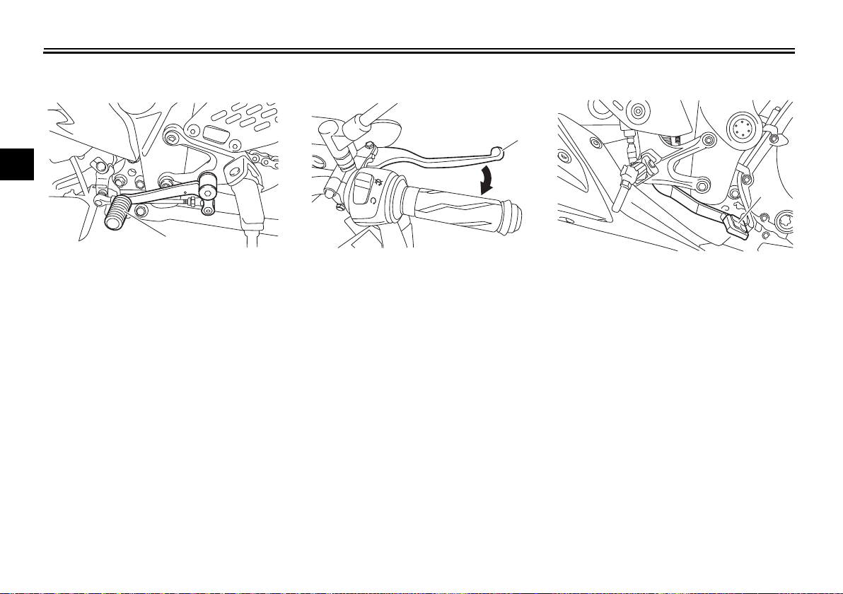
Shift pedal
3
1. Shift pedal
The shift pedal is located on the left
side of the motorcycle and is used in
combination with the clutch lever when
shifting the gears of the 6-speed constant-mesh transmission equipped on
this motorcycle.
EAU12872
EAU12892
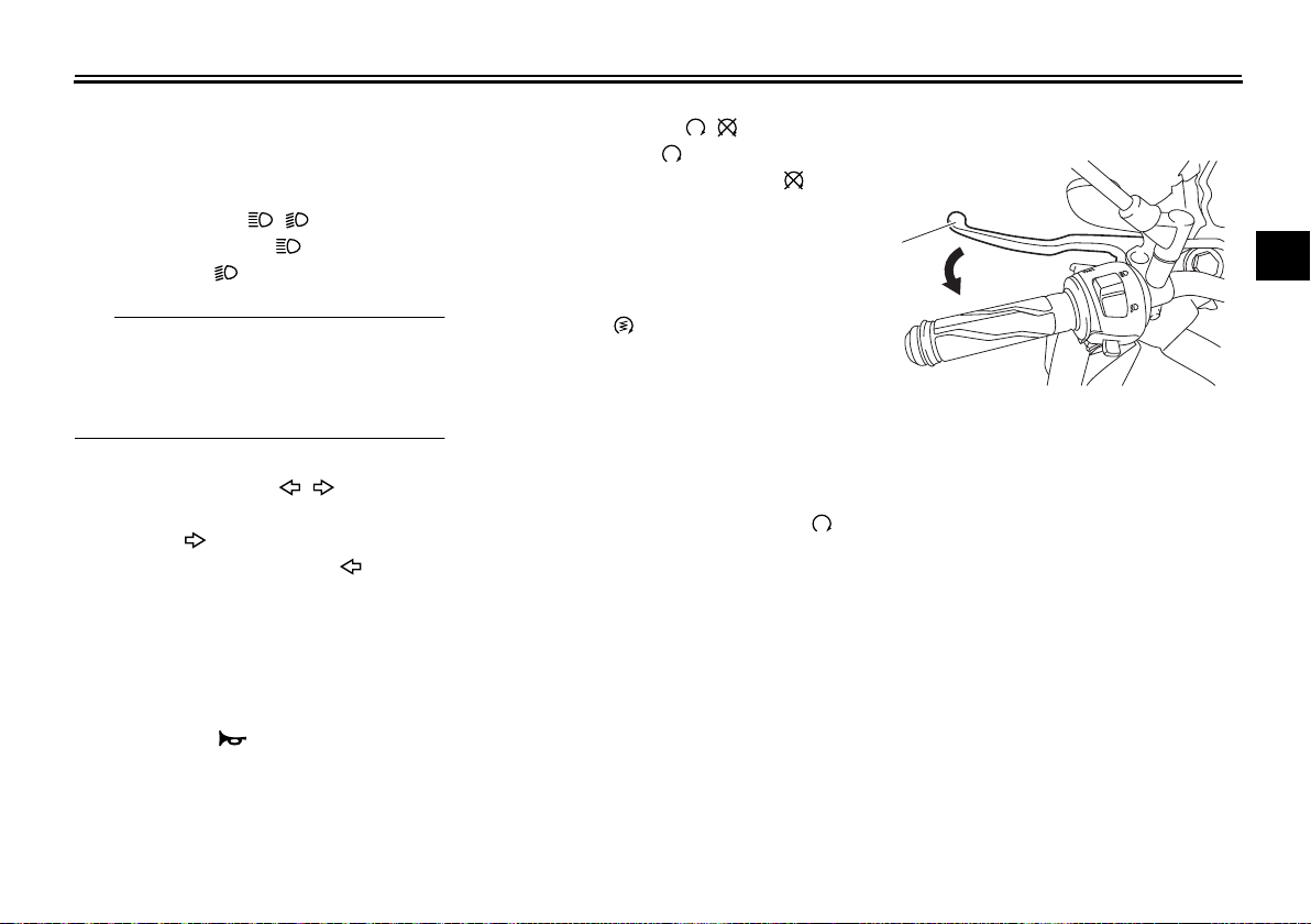
Brake lever
1
1. Brake lever
The brake lever is located on the right
side of the handlebar. To apply the
front brake, pull the lever toward the
throttle grip.
EAU12944
Brake pedal
1. Brake pedal
The brake pedal is located on the right
side of the motorcycle. To apply the
rear brake, press down on the brake
pedal.
3-13
ABS
WARNING
TIP
NOTICE
1
2
The Yamaha ABS (Anti-lock Brake
System) features a dual electronic control system, which acts on the front and
rear brakes independently.
Operate the brakes with ABS as you
would conventional brakes. If the ABS
is activated, a pulsating sensation may
be felt at the brake lever or brake pedal. In this situation, continue to apply
the brakes and let the ABS work; do
not “pump” the brakes as this will reduce braking effectiveness.
Always keep a sufficient distance
from the vehicle ahead to match the
riding speed even with ABS.
The ABS performs best with
long braking distances.
On certain surfaces, such as
rough or gravel roads, the braking distance may be longer with
the ABS than without.
The ABS is monitored by an ECU,
which will revert the system to conventional braking if a malfunction occurs.
EAU63040
EWA16051
Instrument and control functions
The ABS performs a self-diagno-
sis test each time the vehicle first
starts off after the key is turned to
“ON” and the vehicle has traveled
at a speed of 10 km/h (6 mi/h) or
higher. During this test, a “clicking” noise can be heard from the
hydraulic control unit, and if the
brake lever or brake pedal is even
slightly applied, a vibration can be
felt at the lever and pedal, but
these do not indicate a malfunction.
This ABS has a test mode which
allows the owner to experience
the pulsation at the brake lever or
brake pedal when the ABS is operating. However, special tools are
required, so please consult your
Yamaha dealer.
ECA20100
Be careful not to damage the wheel
sensor or wheel sensor rotor; otherwise, improper performance of the
ABS will result.
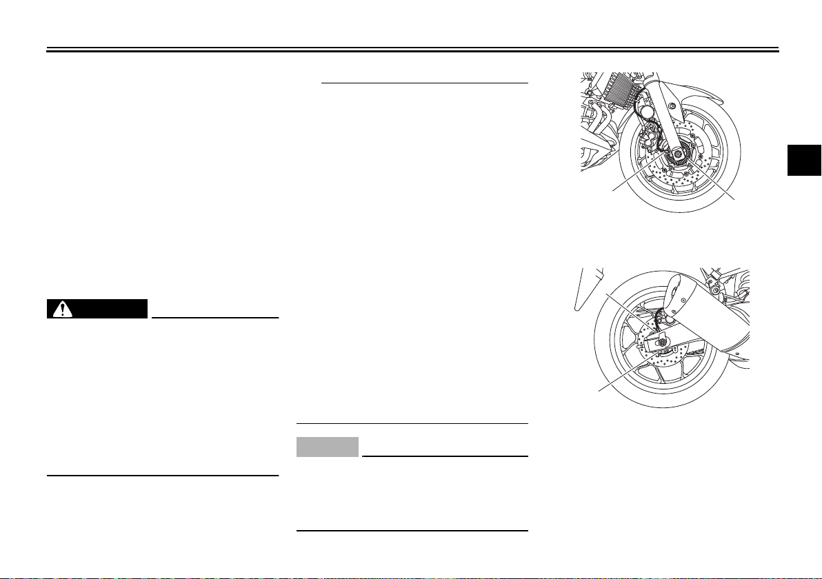
1
1. Front wheel sensor
2. Front wheel sensor rotor
1. Rear wheel sensor
2. Rear wheel sensor rotor
3
2
3-14
 Loading...