

Xylem TX100, TX200 User Manual
TX100/200-SERIES
INSERTION TURBINE
INSTRUCTIONS
TX100/200-SERIES INSERTION TURBINE INSTRUCTIONS
TX101/201
ISO
TX115/215
9001:2008
CERTIFIED COMPANY

TABLE OF CONTENTS
General Information
Features, Specications ......................................................................................................................................Page 1
Installation
Piping, Immersion, Positioning the Meter ..........................................................................................................Page 2
Straight Pipe Recommendations ........................................................................................................................
Full Pipe Recommendations ................................................................................................................................Page 4
Fitting Installation, Meter Installation .................................................................................................................Page 5
Proper Depth Setting, Dimension C, Pipe Wall Thickness .................................................................................Page 6
Set-Up
Connection, Calibration, K-Factors .....................................................................................................................Page 7
Operation
Flow Range, Flow Rates .......................................................................................................................................Page 8
Parts List
Parts Exploded View.............................................................................................................................................Page 9
Troubleshooting & Repair
Troubleshooting, Repair, Rotor Replacement ........................................................................................................ Back
Page 3
TABLES AND DIAGRAMS
Features ............................................................................................................................................................... Page 1
Specifications ...................................................................................................................................................... Page 1
Positioning the Meter .......................................................................................................................................... Page 2
Piping ................................................................................................................................................................... Page 2
Straight Pipe Recommendations .......................................................................................................................
Full Pipe Recommendations ...............................................................................................................................Page 4
Meter Installation ................................................................................................................................................ Page 5
Depth Setting ...................................................................................................................................................... Page 6
Pipe Wall Thickness ............................................................................................................................................ Page 6
Connection Diagram ........................................................................................................................................... Page 7
Parts Exploded View............................................................................................................................................ Page 9
Page 3
Parts List .............................................................................................................................................................. Page 9
Rotor Replacement ................................................................................................................................................ Back
GENERAL INFORMATION
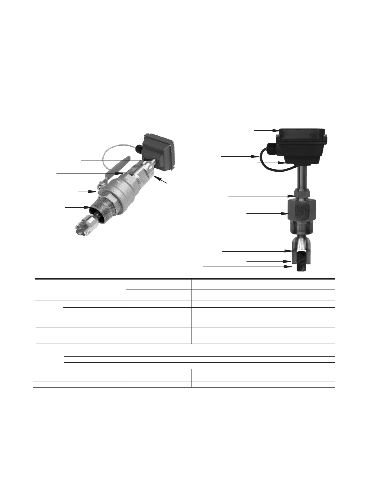
The TX100/200-Series are adjustable depth insertion turbines
that come in brass or 316 stainless models to t 3” to 40”
pipe. Adapters mate with standard 1-1/2" (101/201) or 2”
(115/215) FNPT ttings such as saddles and weldolets which
may be purchased either locally or from Seametrics.
Ruby bearings and a non-drag pickoff give these adjustable
insertion turbine ow sensors a wide ow range and long life.
A sensor detects the passage of miniature magnets in the rotor blades. The resulting square-wave signal can be sent for
hundreds of feet without a transmitter, over unshielded cable.
This signal can be connected directly to many PLC’s and other
controls without any additional electronics.
FEATURES
3/4” diameter tubing
for low insertion force
2” Adapter
removes to mount
hot-tap machine
Full-port 2” ball valve
for sensor removal
Adapter mates
with 2” FNPT
threaded ttings
Locking collar
If desired, a modular system of electronics can be installed
directly on the ow sensor or mounted remotely. The FT415
(battery powered) or FT420 (loop powered) provides digital rate
and total display, as well as programmable pulse; the FT420
also provides a 4-20 mA analog output. The AO55 is a blind
analog (4-20 mA) transmitter. Programmable pulse for pump
pacing is available with the PD10.
The “hot-tap” models (TX115/215) can be installed or serviced
without shutting down the line by means of a 2” full-port isolation valve that comes with a nipple for installation on the pipe
tting. In most circumstances, no special tool is required.
Modular electronics (optional)
• rate/total/pulse/4-20 mA
• blind 4-20 transmitter
• pulse divider
18 Foot Cable
Rugged cast aluminum housing
Compression nut
for easy adjustment, secure locking
Adapter mates with 1-1/2”
FNPT threaded ttings
SPECIFICATIONS*
Power Source
Supply Voltage/Current
Sensor Type
Output
Sinking Current
External Pull-up Resistor
Pipe Size
Materials Housing
Sensor Body
Rotor
Shaft/Bearings
Isolation Valve
Fitting Size Required
Flow Range
Accuracy
Maximum Temperature
Maximum Pressure
Insertion Force
Cable
TX115/215
Rotor housing
Removable jewel bearings
Rotor
Standard Micropowered (-04 Option)
6-40 Vdc/< 2 mA 3.5-16 Vdc/60 µA @ 3.5 Vdc
Magnetoresistive Magnetoresistive
Current Sinking Pulse Current Sinking Pulse
100 mA max 2 mA max
3-40 Vdc ≤ Supply Voltage
TX101/115 TX201/215
3” - 12” (50 - 300mm) 12” - 40” (300 - 890mm)
Cast aluminum
Brass or 316 SS
PVDF standard
Nickel-bound tungsten carbide/Ruby
TX101/201 TX115/215
None Bronze (316SS optional)
1-1/2” FNPT 2” FNPT
0.5 - 30 feet/sec (0.15 - 9.14 meter/sec)
+/-1.5% of full scale
200˚ F (93˚ C)
200 psi (14 bar)
0.44 x pressure in pipe
#22 AWG 3-con, 18’ (6m); 2,000’ (650m) maximum cable run
TX101/201
Note: For larger pipe sizes contact factory
*Specications subject to change. Please consult our website for the most current data (www.seametrics.com).
Page 1
INSTALLATION
10
x Dia.
5
x Dia.
FLOW
An insertion ow sensor measures the velocity of ow at one
point in the pipe; ow rate and total can be inferred from this
one point. Accuracy is decreased by any factor which makes
the ow at the measured point unrepresentative of the entire
ow stream. This includes distorted ow patterns caused by
upstream ttings too close to the sensor. The worst offenders
are ttings that increase the ow on one side of the pipe, such
as partially-opened gate or buttery valves. Fluid moving in a
pipe does not ow at the same velocity. Toward the center of
the pipe, uid moves faster than at the wall, and the relationship between the two changes as overall ow rate increases.
This change in the “velocity prole” can result in non-linearity,
which means that the K-factor (see page 7) that is correct for
one ow rate may be incorrect for another. Recommended
depth settings (see page 6) have been carefully chosen to
minimize this source of error, and should be followed carefully,
especially in the smaller pipe sizes.
Piping. For best results, the TX sensor should be installed with at least ten diameters of straight pipe
upstream and ve downstream. Certain extreme situations
such as partially-opened valves are particularly difcult and
may require more straight diameters upstream. See Straight
Pipe and Full Pipe recommendations on following pages.
Immersion. The TX100/200-Series standard sensors are
not designed for continuous underwater operation. If your
meter may experience occasional temporary immersion, as
in a ooded vault, a unit modied for immersion should be
specied (Option -40).
Positioning the Meter. Horizontal is the preferred installation orientation, since it improves low-ow performance
slightly and avoids problems with trapped air. Bottom, top,
and vertical pipe installaations are all acceptable if required
by the piping layout.
Fair (unacceptable if air is
present)
Best
Fair (unacceptable if uid
contains sediment)
CAUTION: These water meters are
not recommended for installation
downstream of the boiler feedwater
pump where installation fault may
expose the meter to boiler pressure
and temperature. Maximum recom-
mended temperature is 200ºF.
Page 2
 Loading...