

Page 1

6 DECLARATION «CE» DE CONFORMITE
Lowara Srl, ayant son siège à Montecchio Maggiore – Vicence – Italie, déclare que les coffrets
sont conformes aux directives suivantes
• Basse Tension 2006/95/CE
(année de première apposition du marquage: 2000 pour les séries QSM, QM, QTD, QCL, QDR;
2001 pour les séries QMC, QMCS, QPC, QPCS;
2004 pour la série QHI;
2007 pour les séries QDR2, QDRM2, QDRMC, QDRMC2, QYR, QYR2, QGMC;
2008 pour les séries QSC, QSCS
2010 pour les séries QXR2).
• Compatibilité électromagnétique 2004/108/CE
et aux nórmes techniques suivantes
• EN 60439-1 : 2000
• EN 60439-1/A1 : 2005
• EN 61000-6-1 : 2007
• EN 61000-6-3 : 2007
Montecchio Maggiore 11.01.2012
Amedeo Valente
(Director of Engineering and R&D)
1 TRANSPORT
Das Produkt muss sorgfältig angehoben und transportiert werden.
2 EINSCHRÄNKUNGEN DES ANWENDUNGSBEREICHS
Umgebungstemperatur: von -5°C bis +40°C, max. relative Luftfeuchtigkeit: 50% bei +40°C, nicht benetzend.
Sicherstellen, dass die Schalttafel mit der Pumpe vereinbar ist und die Stromaufnahme der Pumpe im Betriebsbereich der Schalttafel liegt.
3 AUFSTELLUNG
Vor der Aufstellung sind die Bedienungsanleitungen der Pumpe aufmerksam zu lesen. Die Schalttafel wandseitig in einem Raum anbringen, in
dem keine Überschwemmungsgefahr besteht, und zwar so, dass die im Datenschild angeführte Schutzart gewahrt bleibt (die
Befestigungslöcher müssen mit den entsprechenden Schrauben abgedeckt und die Kabeln in die entsprechenden Kabeldurchgangslöcher
eingeführt werden).
4 STROMANSCHLUSS
Der Stromanschluss an das Stromnetz und an die Pumpe ist von qualifiziertem Personal unter Beachtung der auf dem Schaltplan angeführten
Hinweise vorzunehmen. Der Schaltplan liegt der Schalttafel bei.
1. Die Speisung mit einem Kabel mit Kabelquerschnitt gemäß herrschenden Normen (auf keinen Fall unter 3G1.5) bereitstellen.
Beachten Sie hierbei die Hinweise, die Sie auf dem Schaltplan im Inneren der Tafel selbst vorfinden (gilt nicht für QSM und QSM/SP,
die bereits mit Kabel und Stecker versehen sind).
Der Erdleiter muss länger als die Phasenleiter sein und vor allen anderen Kabeln angeschlossen werden.
2. Die Speisung der Schalttafel muss eine Kurzschlusssicherung vorsehen sowie eine Differentialvorrichtung, die bei nicht mehr als 30
mA anspricht.
3. Die Speisung der Schalttafel muss eine Netzunterbrechungsvorrichtung mit einer Öffnungsdistanz der Kontakte von mindestens 3 mm
vorsehen.
4. Ist die Schalttafel mit Speisekabel und Stecker ausgestattet, so müssen sich letztere und die entsprechende Steckdose an einem gut
zugänglichen Ort befinden.
5 WARTUNG
Die Schalttafel ist wartungsfrei. Öffnen Sie sie auf keinen Fall, bevor nicht die Netzspannung unterbrochen wurde. Bei Beschädigung des
Speisekabels der Schalttafeln QSM und QSM/SP muss der Austausch von einer unserer Kundendienststellen oder auf jeden Fall von
Fachpersonal vorgenommen werden.
6 «EG» KONFORMITÄTSERKLÄRUNG
Lowara srl, mit Sitz in Montecchio Maggiiore, Vicenza, Italien, erklärt, dass die nachstehend angeführten Schalttafeln
den Vorschriften der folgenden Richtlinien
• Niederspannungsrichtlinie 2006/95/EG
(jahr der ersten Anbringung der Kennzeichnung: 2000 für der Baureihen QSM, QM, QTD, QCL, QDR;
2001 für der Baureihen QMC, QMCS, QPC, QPCS;
2004 für die Baureihe QHI;
2007 für der Baureihen QDR2, QDRM2, QDRMC, QDRMC2, QYR, QYR2, QGMC;
2008 für der Baureihen QSC, QSCS
2010 für der Baureihen QXR2).
• Elektromagnetische Kompatibilität 2004/108/EG
sowie den folgenden technischen Vorschriften entsprechen:
• EN 60439-1 : 2000
• EN 60439-1/A1 : 2005
• EN 61000-6-1 : 2007
• EN 61000-6-3 : 2007
Montecchio Maggiore 11.01.2012
Amedeo Valente
(Director of Engineering and R&D)
QSM, QSM/SP, QMC, QMCS, QPC, QPCS, QSC, QSCS, QDRM, QDRM2, QDRMC,
QDRMC2, QGMC, QDR, QYR, QDR2, QYR2, QM, QTD, QHI, QCL, QXR2
de
QSM, QSM/SP, QMC, QMCS, QPC, QPCS, QSC, QSCS, QDRM, QDRM2, QDRMC,
QDRMC2, QGMC, QDR, QYR, QDR2, QYR2, QM, QTD, QHI, QCL, QXR2
Page 2
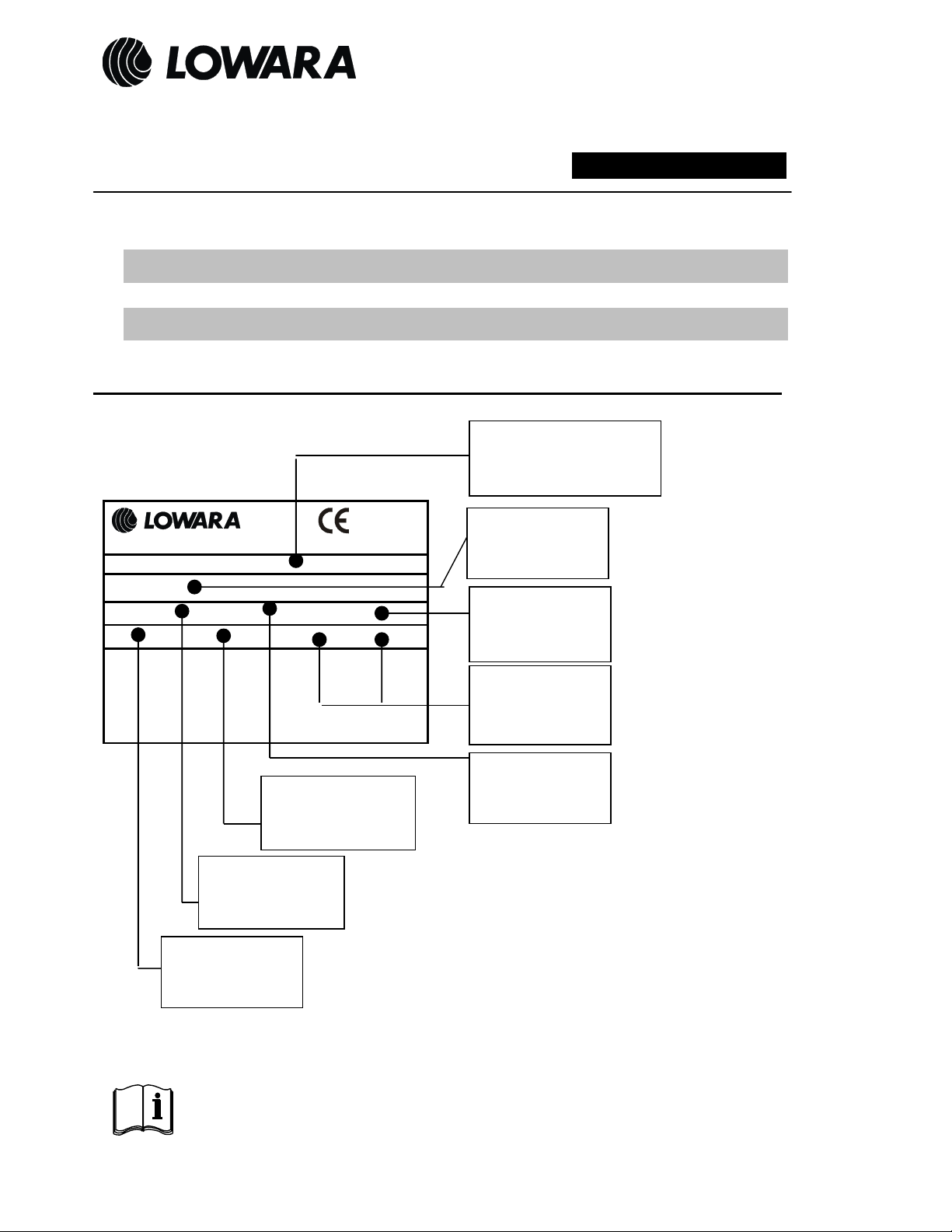
it
Quadro di comando
.
en
Control box
fr
Targa Dati
Nameplate
Plaque signalétique
Datenschild
MONTECCHIO MAGGIORE – VI - ITALY
Control box
Cod.
Coffret Electrique
de
Schalttafel
V
Corrente nominale
Rated current
Courant nominal
Nennstrom
it Conservate con cura il manuale per future consultazioni
en Save this manual for future reference
fr Conservez avec soin le manuel pour toute consultation future
de Das handbuch muss fur zukunftige Konsultationen sorgfaltig aufbewahrt werden
Instruction for installation, Safety recommendation.
QDRM-QDRM2-QDRMC-QDRMC2- QXR2-QGMC-QDR- QYR-QDR2-QYR2-QCL
~
1
IP A
Tensione nominale
Rated Voltage
Tension nominale
Nennspannung
Istruzioni d’installazione, Raccomandazioni di sicurezza
Instruction d’installation, Recommandation de sécurité.
Installationsanleitungen und Sicherheitshinweise
QSM-QMC-QMCS-QPC-QPCS-QSC-QSCS-QM-QTD-QHI
Tipo di quadro
Type of control box
Model de coffret
Schalttafel Typ
Codice
Part number
Référence
Code
Frequenza
Hz
µF /
MADE IN ITALY
Grado di protezione
IP Degree
Indice de protection
Shutzart
V
Frequency
Fréquence
Frequenz
Condensatore
Capacitor
Condensateur
Kondensator
Nr. Fasi
Nr. Phase
Nr. Phases
Phasenanzahl
cod. 001072910 E 01/12
Page 3

IMPIEGHI - APPLICATIONS – UTILISATIONS – ANWENDUNGEN
Quadro - Control box
Coffret - Schalttafel
QSM - QMC - QMCS
QPC - QPCS - QSC- QSCS
QSM/SP- QCL
QDRM - QDRMC
QDRM2 – QDRMC2
QXR2
QDR - QYR
QDR2 – QYR2
QM -QCL
QTD
1 MOVIMENTAZIONE
Il prodotto va sollevato e movimentato con cura.
2 LIMITI D’IMPIEGO
Temperatura ambiente: -5°C +40°C , Umidità relativa max : 50% a 40°C senza condensa.
Verificare che il quadro sia idoneo alla pompa e che l’assorbimento di corrente della pompa sia compreso nel campo di funzionamento del
quadro
3 INSTALLAZIONE
Prima dell’installazione leggere attentamente le istruzioni della pompa. Installare il quadro a parete in un ambiente non a rischio di allagamento.
Installare il quadro mantenendo il grado di protezione IP riportato sulla targa (i fori di fissaggio devono essere impegnati dalle relative viti e i
pressacavi dai relativi cavi)
4 COLLEGAMENTO ELETTRICO
Il collegamento alla rete elettrica ed alla pompa deve essere eseguito da personale qualificato seguendo le indicazioni sullo schema di
collegamento allegato al quadro.
1. Collegare l’ alimentazione con cavo di sezione adeguata nel rispetto delle normative vigenti, comunque non inferiore a 3G1.5, e seguendo
le indicazioni dello schema riportato all’ interno del quadro (Escluso QSM e QSM/SP già dotati di cavo con spina )
Il conduttore di terra va lasciato più lungo dei conduttori di fase e collegato per primo.
2. L’ alimentazione del quadro deve prevedere un dispositivo di protezione dal cortocircuito, e un dispositivo differenziale con corrente di
intervento non superiore a 30 mA.
3. L’ alimentazione del quadro deve prevedere un dispositivo di sconnessione dalla rete con distanza di apertura dei contatti di almeno 3 mm.
4. Nel caso che il quadro sia corredato con cavo di alimentazione e spina, quest’ ultima e la relativa presa devono essere posizionate in un
luogo ben accessibile.
5 MANUTENZIONE
Il quadro non necessita di manutenzione. Non aprire il quadro prima di averlo scollegato dalla rete di alimentazione. In caso di danneggiamento
del cavo di alimentazione del quadri QSM e QSM/SP la sostituzione deve essere eseguita dai nostri Centri Assistenza o comunque da
personale qualificato
6 DICHIARAZIONE «CE» DI CONFORMITA’
Lowara srl , con sede a Montecchio Maggiore – Vicenza – Italia, dichiara che i quadri elettrici
QSM, QSM/SP, QMC, QMCS, QPC, QPCS, QSC, QSCS, QDRM, QDRM2, QDRMC,
sono conformi alle seguenti Direttive
• Bassa Tensione 2006/95/CE
(anno di prima apposizione della marcatura: 2000 per le serie QSM, QM, QTD, QCL, QDR;
2001 per le serie QMC, QMCS, QPC, QPCS;
2004 per la serie QHI;
2007 per le serie QDR2, QDRM2, QDRMC, QDRMC2, QYR, QYR2, QGMC;
2008 per le serie QSC, QSCS
2010 per le serie QXR2).
• Compatibilità Elettromagnetica 2004/108/CE
e alle seguenti norme tecniche
• EN 60439-1 : 2000
• EN 60439-1/A1 : 2005
• EN 61000-6-1 : 2007
• EN 61000-6-3 : 2007
Montecchio Maggiore 11.01.2012
Amedeo Valente
(Director of Engineering and R&D)
Pompa - Pump
Pompe - Pumpe
Sommerse 1 ∼ Submersible 1 ∼
Immergees 1 ∼ Tauchmotorpumpen 1 ∼
Sommergibili da drenaggio 1 ∼ Submersible Drainage 1 ∼
Submersibles 1 ∼ Abwasserpumpen 1 ∼
Sommergibili da drenaggio 3 ∼ Submersible Drainage 3 ∼
Submersibles 3 ∼ Abwasserpumpen 3 ∼
Superficie 1 ∼ Surface 1 ∼
Surface 1 ∼ Blockpumpen 1 ∼
Superficie 3 ∼ Surface 3 ∼
Surface 3 ∼ Blockpumpen 3 ∼
it
QDRMC2, QGMC, QDR, QYR, QDR2, QYR2, QM, QTD, QHI, QCL, QXR2
en
Page 4

1 HANDLING
The product must be lifted and handled with care.
2 APPLICATION LIMITS
Ambient temperature: -5°C +40°C , Max relative humidity : 50% at 40°C no condensation phenomena.
Check that control box is suitable for the pump and pump current matches control box amperage range
3 INSTALLATION
Before installation read carefully pump instructions. Install the control box on the wall in a room without risk of water overflow. Mount the control
box in such a way to maintain the IP protection grade in the nameplate (Fixing holes must be occupied with theirs screws and cable entries with
their cables)
4 ELECTRICAL CONNECTION
The connections to the electrical mains and to the pump must be executed by qualified personnel following wiring diagrams enclosed to the
control box
1 Connect the power by means of a cord with suitable section in accordance with applicable standards, but not lower than 3G1.5, and
following the instruction of the diagram inside the control box (Except QSM and QSM/SP already equipped with cord and plug )
The ground cable has to be left longer than phase cables and it has to be connected first.
2 The power of the control box must foresee a short circuit protection device, and a differential device with working current not higher than
30 mA.
3 The control box must foresee a disconnection device from mains with opening contact of at least 3 mm .
4 In the case the control box is equipped with cord and plug, this last and relative socket must be positioned in a place easily to be reached.
5 MAINTENANCE
The control box requires no maintenance. Do not open the control box before having disconnected it from the power mains. In case of damage
of the power cord of control boxes QSM and QSM/SP, the replacement must be done by our Assistance Centres or by qualified personnel
only
6 «EC» DECLARATION OF CONFORMITY
Lowara srl, with headquartes in Montecchio Maggiore – Vicenza- Italy, hereby declares that control boxes
comply with the following Directives
• Low Voltage 2006/95/EC
(year of first use of the mark: 2000 for series QSM, QM, QTD, QCL, QDR;
2001 for series QMC, QMCS, QPC, QPCS;
2004 for series QHI;
2007 for series QDR2, QDRM2, QDRMC, QDRMC2, QYR, QYR2, QGMC;
2008 for series QSC, QSCS
2010 for series QXR2).
• Electromagnetic Compatibility 2004/108/EC
e with the following technical standards
• EN 60439-1 : 2000
• EN 60439-1/A1 : 2005
• EN 61000-6-1 : 2007
• EN 61000-6-3 : 2007
Montecchio Maggiore 11.01.2012
Amedeo Valente
(Director of Engineering and R&D)
1 TRANSPORT
Le coffret doit être manipulé avec attention
2 LIMITE D’UTILISATION
Température ambiante: -5°C +40°C
Humidité relative maxi: 50% a 40°C sans condensa.
Vérifier que le coffret soit adapté à la pompe et que l’intensité absorbée par la pompe soit comprise dans les tolérances de fonctionnement de
ce coffret.
3 INSTALLATION
Avant l’installation, lire attentivement le manuel d’instruction de la pompe. Installer le coffret au mur dans une local sec sans risque d’inondation.
Installer le coffret de façon à conserver le degré de protection IP réporté sur la plaque signalétique. (Utiliser les vis relatives aux trous prévus
pour la fixation du coffret, ainsi que les presses étoupes adaptés aux câbles).
4 CONNECTIONS ELECTRIQUES
Les connections électriques au réseau électrique et à la pompe doivent être effectuée par un personnel qualifié et conformément au schéma
fourni avec le coffret.
1. Connecter l’alimentation avec un câble de section adaptée et dans le respect des normes en vigueur, dans tous les cas supérieur ou
égal à 3G1.5, et selon les indications du schéma rapportées à l’intérieur du coffret (exclus les QSM et QSM/SP déjà fournis avec
câble et prise électrique).
2. L’alimentation du coffret doit être protégée par un disjoncteur différentiel.
3. Effectuer la connexion au secteur par l’intermédiarie d’un interrupteur avec une distance entre les contacts d’au moins 3mm.
4. Dans le cas où le coffret est équipé d’un câble d’alimentation et d’une prise électrique mâle, cette dernière ainsi que la prise
électrique murale doivent être placée dans un lieu bien accessible.
5 MANUTENTION
Le coffret ne nécessite aucune manutention. Ne pas ouvrir le coffret avant de l’avoir déconnecté de l’alimentation électrique. En cas de
dommage du câble électrique le remplacement doit être effectué par un personnel qualifié.
QSM, QSM/SP, QMC, QMCS, QPC, QPCS, QSC, QSCS, QDRM, QDRM2, QDRMC,
QDRMC2, QGMC, QDR, QYR, QDR2, QYR2, QM, QTD, QHI, QCL, QXR2
fr
 Loading...