

Page 1
OPERATING MANUAL
M
ENU
OK
ba75576e05 11/2013
ProLab 1000
pH/ISE
MEASURING INSTRUMENT WITH AUTOMATIC SENSOR RECOGNITION
AND ELECTRONIC ACCESS CONTROL
Page 2

ProLab 1000
CE conformity
Radio data transmission
SI Analytics GmbH hereby declares that the ProLab 1000 meter is in
compliance with the basic requirements and the other relevant
regulations of the directive 1999/5/EC.
The EC declaration of conformity can be requested from SI Analytics
GmbH.
Copyright © 2009, SI Analytics GmbH
Reprinting - even as excerpts - is only allowed with the explicit written
authorization of SI Analytics GmbH, Mainz.
Printed in Germany.
2 ba75576e05 11/2013
Page 3

ProLab 1000
KONFORMITÄTSERKLÄRUNG
DECLARATION OF CONFORMITY
DÉCLARATION DE CONFORMITÉ
Wir erklären in alleiniger
Verantwortung, dass das
Produkt
pH-/ISE-Messgerät
ProLab 1000
auf das sich diese Erklärung
bezieht, übereinstimmt mit
den Angaben im Kapitel
We declare under our sole
responsibility that the
product
pH / ISE measuring
instrument
ProLab 1000
to which this declaration
relates is in conformity with
the specifications in the
chapter
Nous déclarons sous notre
seule responsabilité que le
produit
Appareil de mesure
pour pH/ISE
ProLab 1000
auquel se réfère cette
déclaration est conforme aux
indications du chapitre
3. März, March 3, 3 mars 2010
AGQSF 0000-A105-02/100303
SI Analytics GmbH
Hattenbergstr. 10
D-55122 Mainz
Deutschland, Germany, Allemagne
Technische Daten
pH-/ISE-Messgerät
ProLab 1000
3. März 2010
ba75576e05 11/2013 3
Page 4

ProLab 1000
4 ba75576e05 11/2013
Page 5

ProLab 1000 Contents
Contents
1 Overview . . . . . . . . . . . . . . . . . . . . . . . . . . . . . . . . . . . . . . 7
1.1 General features . . . . . . . . . . . . . . . . . . . . . . . . . . . . . . . 7
1.2 Keypad . . . . . . . . . . . . . . . . . . . . . . . . . . . . . . . . . . . . . . . 8
1.3 Display . . . . . . . . . . . . . . . . . . . . . . . . . . . . . . . . . . . . . . . 9
1.4 Socket field . . . . . . . . . . . . . . . . . . . . . . . . . . . . . . . . . . . 10
1.5 Automatic sensor recognition . . . . . . . . . . . . . . . . . . . . . 11
1.6 Electronic access control . . . . . . . . . . . . . . . . . . . . . . . . 13
2 Safety . . . . . . . . . . . . . . . . . . . . . . . . . . . . . . . . . . . . . . . 15
2.1 Authorized use . . . . . . . . . . . . . . . . . . . . . . . . . . . . . . . . 15
2.2 General safety instructions . . . . . . . . . . . . . . . . . . . . . . . 16
3 Commissioning . . . . . . . . . . . . . . . . . . . . . . . . . . . . . . . 17
3.1 Scope of delivery . . . . . . . . . . . . . . . . . . . . . . . . . . . . . . 17
3.2 Power supply . . . . . . . . . . . . . . . . . . . . . . . . . . . . . . . . . 17
3.3 Initial commissioning . . . . . . . . . . . . . . . . . . . . . . . . . . . 18
4 Operation . . . . . . . . . . . . . . . . . . . . . . . . . . . . . . . . . . . . 19
4.1 Switch the meter on and off . . . . . . . . . . . . . . . . . . . . . . 19
4.2 General operating principles . . . . . . . . . . . . . . . . . . . . . 20
4.2.1 Operating modes . . . . . . . . . . . . . . . . . . . . . . . . 20
4.2.2 Navigation . . . . . . . . . . . . . . . . . . . . . . . . . . . . . 21
4.2.3 Navigation example 1: Setting the language . . . 23
4.2.4 Navigation example 2: Setting the date and time 25
4.3 Access control . . . . . . . . . . . . . . . . . . . . . . . . . . . . . . . . 27
4.3.1 Administrating access authorizations . . . . . . . . 27
4.3.2 Lost your electronic key? . . . . . . . . . . . . . . . . . 29
4.3.3 Lock . . . . . . . . . . . . . . . . . . . . . . . . . . . . . . . . . . 29
4.4 System settings (system menu) . . . . . . . . . . . . . . . . . . . 30
4.4.1 Data storage . . . . . . . . . . . . . . . . . . . . . . . . . . . 30
4.4.2 Display . . . . . . . . . . . . . . . . . . . . . . . . . . . . . . . 30
4.4.3 System . . . . . . . . . . . . . . . . . . . . . . . . . . . . . . . 31
4.4.4 Automatic Stability control . . . . . . . . . . . . . . . . . 32
4.5 pH value / ORP voltage . . . . . . . . . . . . . . . . . . . . . . . . . 33
4.5.1 General information . . . . . . . . . . . . . . . . . . . . . . 33
4.5.2 Measuring the pH value . . . . . . . . . . . . . . . . . . 34
4.5.3 Measuring the ORP . . . . . . . . . . . . . . . . . . . . . . 36
4.5.4 Settings for pH and ORP measurements . . . . . 38
4.5.5 pH calibration . . . . . . . . . . . . . . . . . . . . . . . . . . 40
4.5.6 Calibration interval . . . . . . . . . . . . . . . . . . . . . . 46
4.5.7 Calibrating . . . . . . . . . . . . . . . . . . . . . . . . . . . . . 47
4.5.8 Measurements with dead stop function . . . . . . . 51
4.6 Ion concentration . . . . . . . . . . . . . . . . . . . . . . . . . . . . . . 52
4.6.1 General information . . . . . . . . . . . . . . . . . . . . . . 52
4.6.2 Measuring the ion concentration . . . . . . . . . . . 53
4.6.3 Settings for ISE measurements . . . . . . . . . . . . 54
4.6.4 Calibrating for ISE measurements . . . . . . . . . . 55
ba75576d05 11/2013
5
Page 6

Contents ProLab 1000
4.7 Storage . . . . . . . . . . . . . . . . . . . . . . . . . . . . . . . . . . . . . . 61
4.7.1 Manual storage . . . . . . . . . . . . . . . . . . . . . . . . . 62
4.7.2 Automatic storage at intervals . . . . . . . . . . . . . . 63
4.7.3 Reading the measurement data storage . . . . . . 65
4.7.4 Erasing the data storage . . . . . . . . . . . . . . . . . . 68
4.7.5 Displaying and downloading calibration records 68
4.7.6 Displaying and downloading calibration history . 70
4.8 Transmitting data (to a PC or printer) . . . . . . . . . . . . . . . 71
4.8.1 RS232 interface . . . . . . . . . . . . . . . . . . . . . . . . . 71
4.8.2 USB interface (device) . . . . . . . . . . . . . . . . . . . . 72
4.8.3 Options for data transmission . . . . . . . . . . . . . . 73
4.8.4 Operation with MultiLab pilot . . . . . . . . . . . . . . . 74
4.9 Reset . . . . . . . . . . . . . . . . . . . . . . . . . . . . . . . . . . . . . . . 74
4.9.1 Resetting the sensor settings . . . . . . . . . . . . . . 74
4.9.2 Resetting the system settings . . . . . . . . . . . . . . 75
5 Maintenance, cleaning, disposal . . . . . . . . . . . . . . . . . 77
5.1 Maintenance . . . . . . . . . . . . . . . . . . . . . . . . . . . . . . . . . . 77
5.2 Cleaning . . . . . . . . . . . . . . . . . . . . . . . . . . . . . . . . . . . . . 78
5.3 Disposal . . . . . . . . . . . . . . . . . . . . . . . . . . . . . . . . . . . . . 78
6 What to do if... . . . . . . . . . . . . . . . . . . . . . . . . . . . . . . . .79
6.1 pH and ORP measurement . . . . . . . . . . . . . . . . . . . . . . 79
6.2 ISE measurement . . . . . . . . . . . . . . . . . . . . . . . . . . . . . . 81
6.3 General errors . . . . . . . . . . . . . . . . . . . . . . . . . . . . . . . . . 82
7 Technical data . . . . . . . . . . . . . . . . . . . . . . . . . . . . . . . . 83
7.1 General data . . . . . . . . . . . . . . . . . . . . . . . . . . . . . . . . . . 83
7.2 Measuring ranges, resolution, accuracy . . . . . . . . . . . . . 84
7.2.1 pH/ORP . . . . . . . . . . . . . . . . . . . . . . . . . . . . . . . 84
7.2.2 ISE . . . . . . . . . . . . . . . . . . . . . . . . . . . . . . . . . . . 85
8 Lists . . . . . . . . . . . . . . . . . . . . . . . . . . . . . . . . . . . . . . . . . 87
Index . . . . . . . . . . . . . . . . . . . . . . . . . . . . . . . . . . . . . . . . 93
Appendix . . . . . . . . . . . . . . . . . . . . . . . . . . . . . . . . . . . . . . 95
A.1 Firmware update . . . . . . . . . . . . . . . . . . . . . . . . . . . . . . . 95
A.2 Menus . . . . . . . . . . . . . . . . . . . . . . . . . . . . . . . . . . . . . . . 97
A.2.1 Data storage . . . . . . . . . . . . . . . . . . . . . . . . . . . 97
A.2.2 Display . . . . . . . . . . . . . . . . . . . . . . . . . . . . . . . . 98
A.2.3 System . . . . . . . . . . . . . . . . . . . . . . . . . . . . . . . . 98
A.2.4 <STO
A.2.5 <PRT
A.2.6 pH/U . . . . . . . . . . . . . . . . . . . . . . . . . . . . . . . . . 100
A.2.7 ISE . . . . . . . . . . . . . . . . . . . . . . . . . . . . . . . . . . 101
_> . . . . . . . . . . . . . . . . . . . . . . . . . . . . . . 99
_> . . . . . . . . . . . . . . . . . . . . . . . . . . . . . . 99
6
ba75576d05 11/2013
Page 7
ProLab 1000 Overview
M
ENU
OK
1
2
4
3
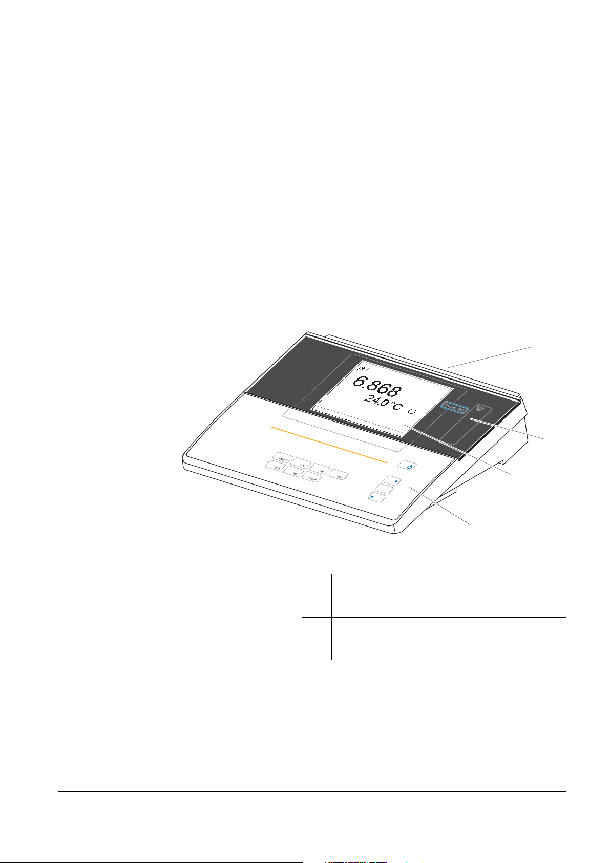
1Overview
1.1 General features
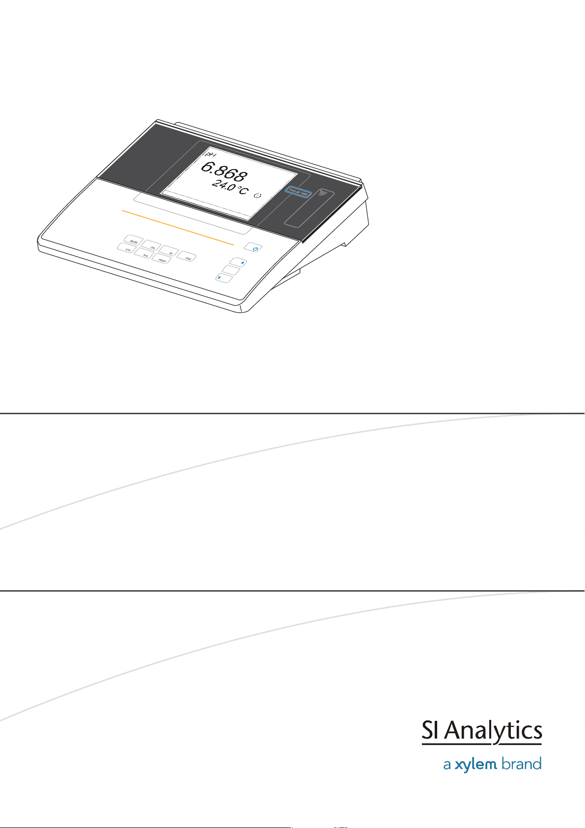
The ProLab 1000 precision pH meter enables you to perform pH, ORP
and ion-selective measurements rapidly and reliably.
The ProLab 1000 provides the maximum degree of ease of use,
reliability and, above all, measuring certainty for all applications.
The proven calibration procedures, and stability control function (SC)
and the sensor recognition function support your work with the meter.
In addition, the ProLab 1000 provides an electronic access control.
Documented measurement data is thus automatically assigned to a
user.
ba75576e05 11/2013
1 Keypad
2 Display
3 Reader field for electronic access control
4 Socket field
7
Page 8
Overview ProLab 1000
MENU
OK
SCMODE
STO
ESC
PRINT
CAL
RCL
MODE
CAL
SC
STO
RCL
PRINT
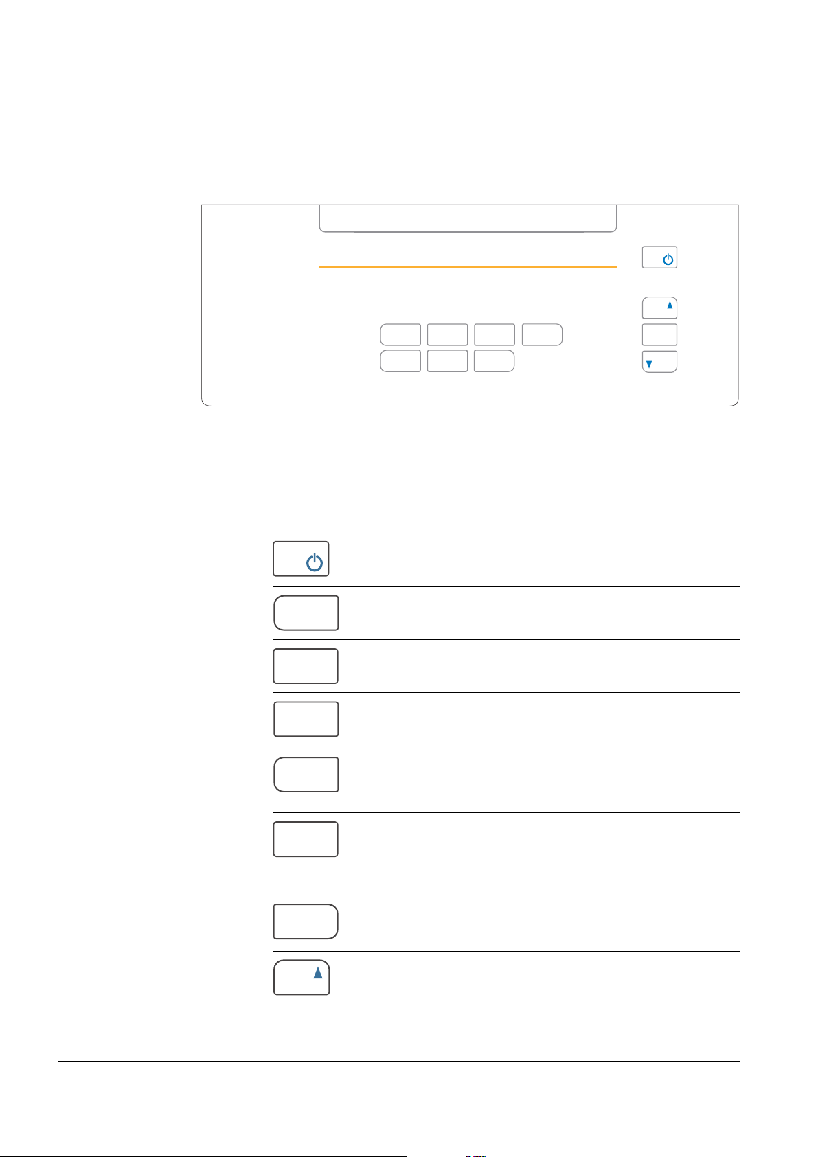
1.2 Keypad
In this operating manual, keys are indicated by brackets <..> .
The key symbol (e.g. <MENU/OK>) generally indicates a short
keystroke (under 2 sec) in this operating manual. A long keystroke
(approx. 2 sec) is indicated by the underscore behind the key symbol
(e.g. <MENU/OK
_>).
Key functions
<On/Off> Switch the meter on/off
<MODE>
<MODE
<CAL>
<CAL
<SC> Switch on or off the stability control
<STO>
<STO
<RCL>
<RCL
<PRINT>
<PRT
_>
_>
_>
_>
_>
Select measured parameter
Activate operation lock
Call up calibration procedure
Open menu for calibration data storage
function manually.
Store measured value
Open menu for automatic storing
function
Open menu for manually stored
measured values
Open menu for automatically stored
measured values
Print
Open menu for automatic printing
<▲> Increment values, scroll
8
ba75576e05 11/2013
Page 9
ProLab 1000 Overview
MENU
OK
ESC
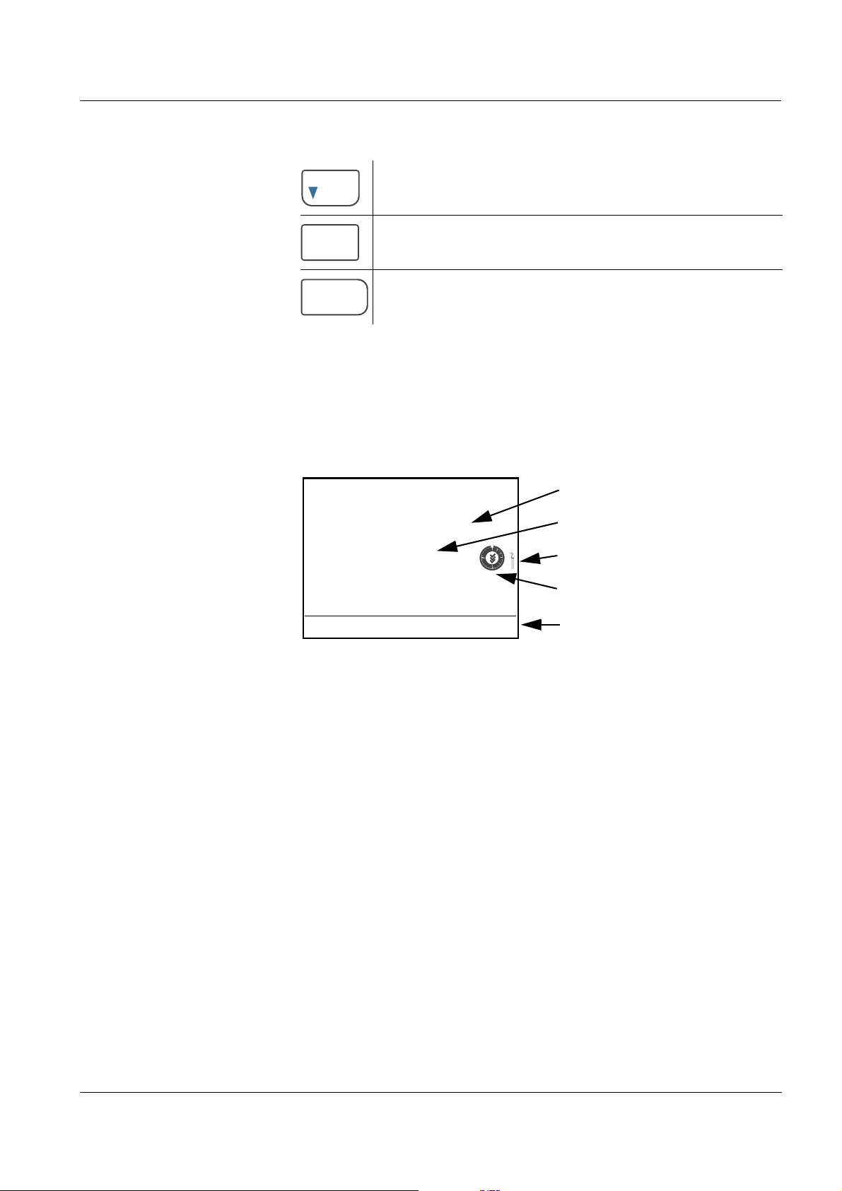
Measured value (with unit)
Temperature display
ID sensor symbol
CalClock
Status line
pH
7.000
25.0 °C
26.04.06 10:37
<▼> Decrement values, scroll
<MENU/OK>
<MENU/OK
<ESC> Return to higher menu level /
_>
Confirm entries
Open setting menu for system settings
Cancel inputs
1.3 Display
The graphic display displays the measurement data. The illumination
enables to read the display even in the darkness.
ba75576e05 11/2013
9
Page 10
Overview ProLab 1000
1
2
3
6
7
8
4
5
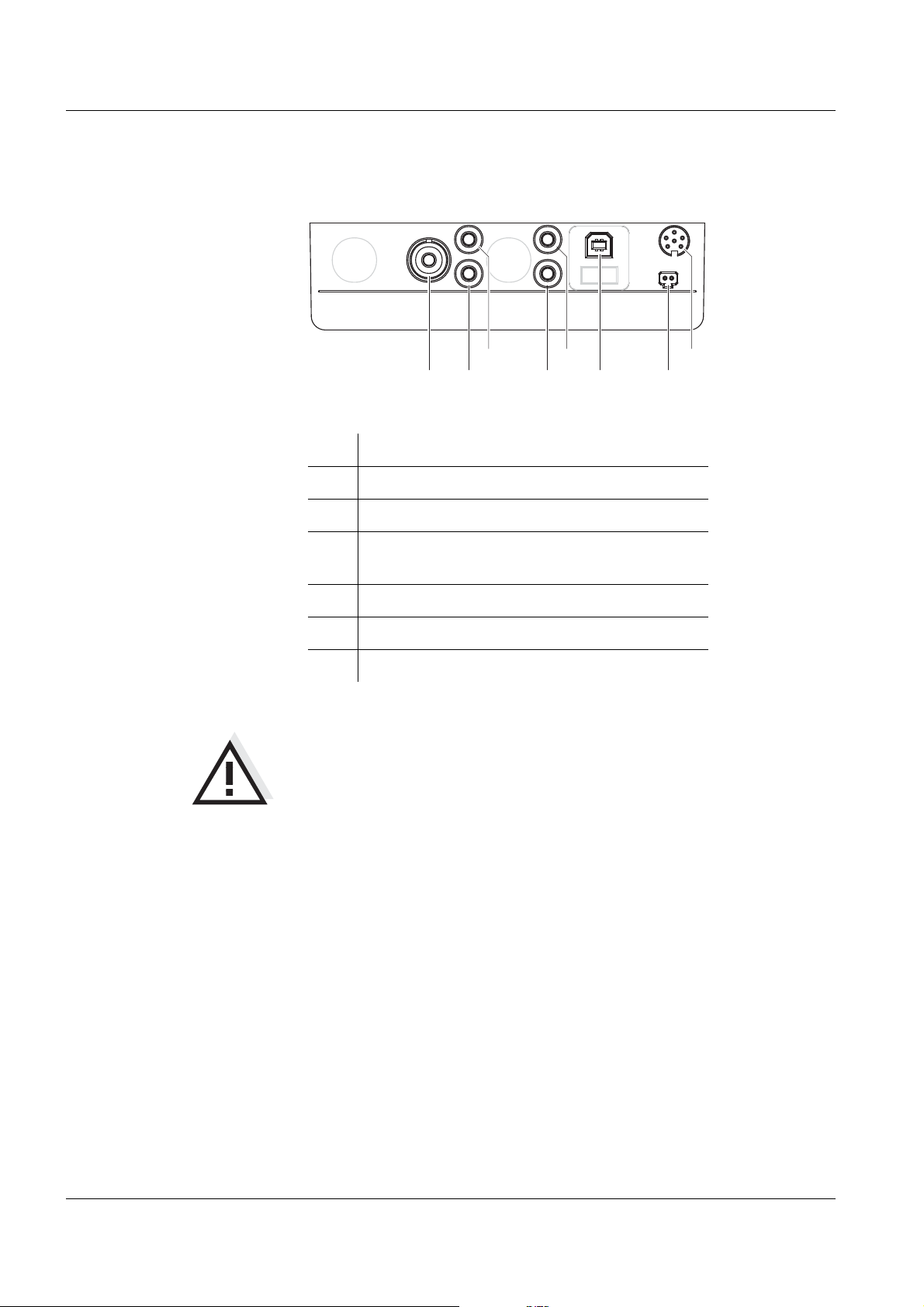
1.4 Socket field
Connections:
1 pH electrode
2 + 4 Reference electrode
3 Temperature sensor
5 Dead stop connection
(e.g. for double platinum electrodes)
6 USB interface
7 Power pack
8 RS232 interface/analog output
CAUTION
Only connect sensors to the meter that cannot return any voltages
or currents that are not allowed (> SELV and > current circuit with
current limiting).
Nearly all commercial sensors - especially SI Analytics sensors fulfill these requirements.
10
ba75576e05 11/2013
Page 11
ProLab 1000 Overview
DIN
BNC
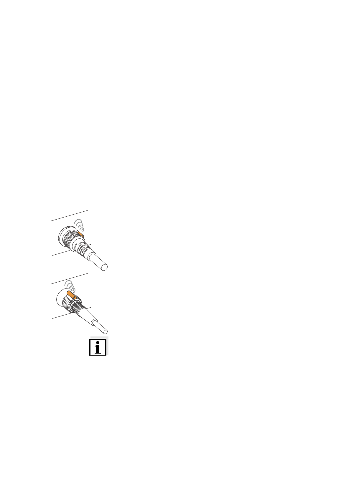
1.5 Automatic sensor recognition
The automatic sensor recognition function enables
to operate a sensor with different meters without recalibrating
to operate different sensors with one meter without recalibrating
to assign measurement data to a sensor
– measurement datasets are always downloaded to the interface
with the sensor type and sensor series number.
– measurement datasets are always stored together with the
sensor type and sensor series number.
to assign calibration data to a sensor
– calibration data is always downloaded to the interface with the
sensor type and sensor series number.
To be able to use the automatic sensor recognition function a meter is
required that supports the automatic sensor recognition (e.g.
ProLab 1000), and a sensor (ID sensor) that is suitable for sensor
recognition.
In every ID sensor, sensor data is stored that clearly identifies the
sensor.
The sensor data is sent to the meter automatically via radio
communication and used for sensor identification there.
Note
With the ProLab 1000 meter, you can also operate non-ID sensors.
Then, however, you cannot use the advantages of the sensor
recognition function.
ba75576e05 11/2013
11
Page 12
Overview ProLab 1000
pH
7.000
25.0 °C
26.04.06 10:37
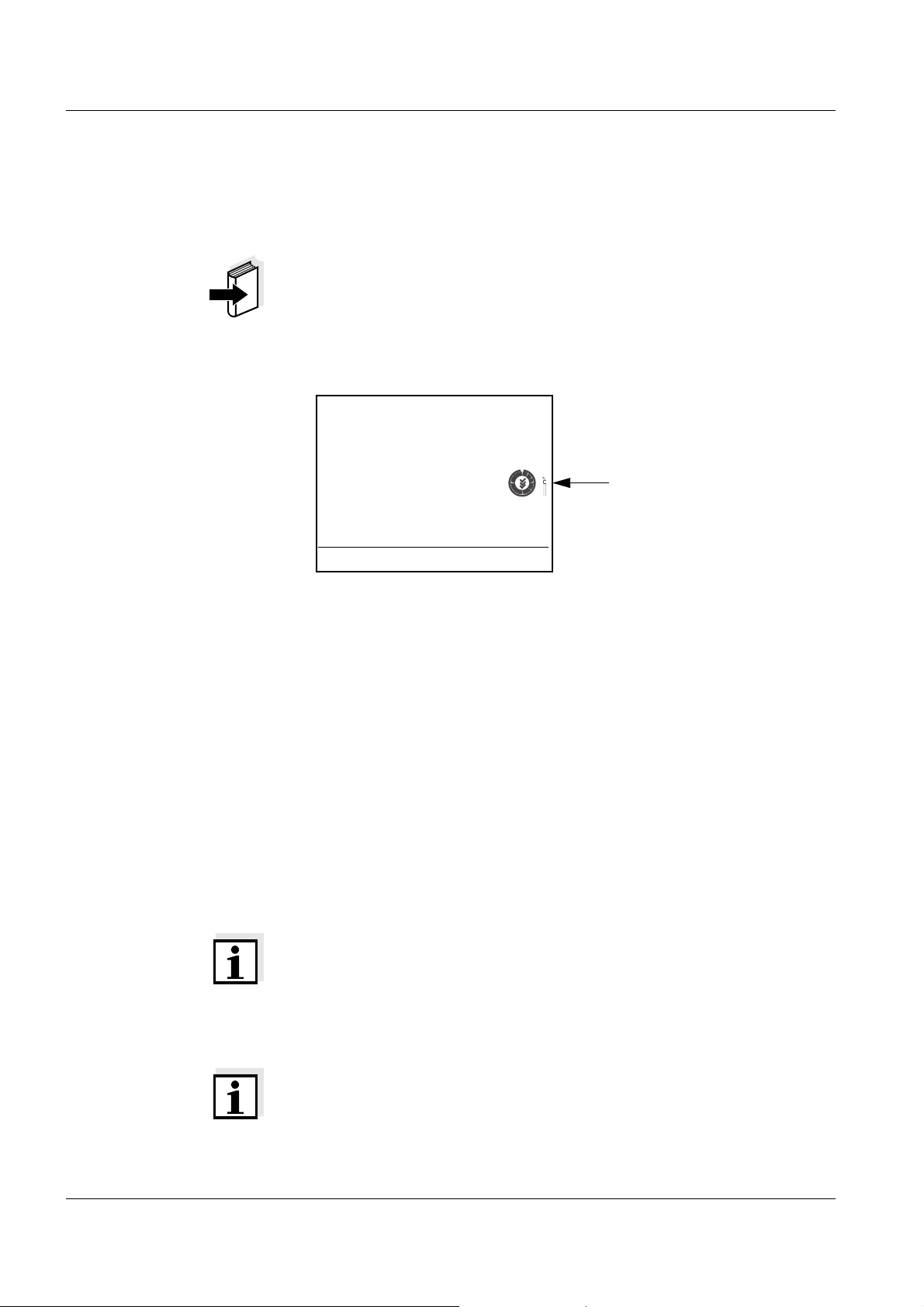
ID sensor symbol
ID sensors SI Analytics ID sensors support the automatic sensor recognition
function. Their sensor designation has the addition "ID", e.g.
A 161 1M DIN-ID electrode.
Note
Information on available ID sensors is given on the Internet or directly
by SI Analytics.
ID sensors connected to the ProLab 1000 meter can be recognized by
the ID sensor symbol on the display of the meter.
Sensor data from ID
sensors
ID sensors transmit the following sensor data to the meter:
SENSOR ID
– Sensor type
– Sensor series number
Calibration data
– Calibration date
– Calibration characteristics
– Calibration interval
– Selected buffer set (pH electrodes only)
The calibration data is updated in the ID sensor after each calibration
procedure. The ID sensor symbol flashes while this is done.
Note
While the ID sensor symbol is flashing, the sensor must not be
disconnected because otherwise the calibration data will not be
completely transmitted. The sensor will then have no valid calibration.
Note
If non-ID sensors are used, the calibration data from the meter is used
and also stored in the meter.
12
ba75576e05 11/2013
Page 13
ProLab 1000 Overview
MENU
OK
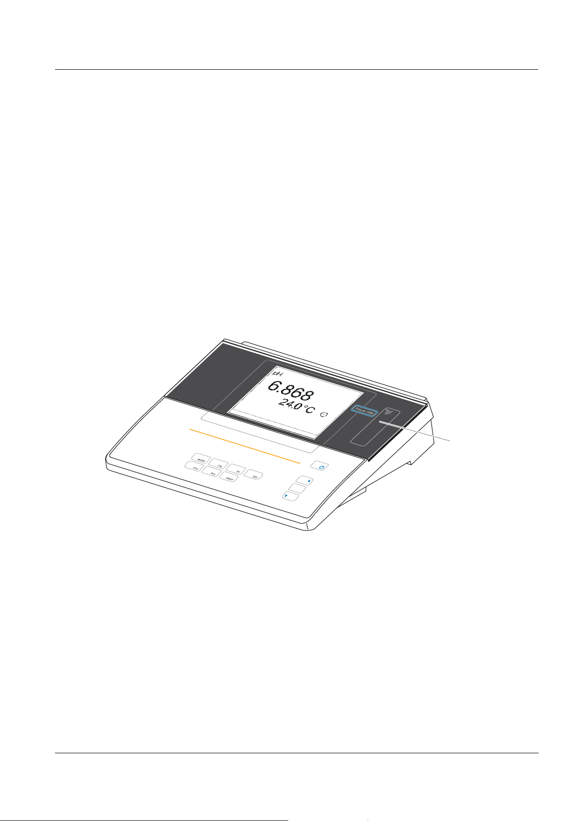
Reader unit for
access control
1.6 Electronic access control
The ProLab 1000 always documents measurement data and
calibration data with an ID number (USER ID).
If the USER ID is assigned to a certain user, all measurement data is
also assigned to the user in compliance with GLP.
The USER ID is easily and safely transmitted to the ProLab 1000 via
an electronic key. Each electronic key in the form of a keyring pendant
contains a key number. The key number is read by the meter via a
contactless radio data connection and used as the USER ID.
The meter checks the access authorization for the USER ID.
Measurements with an electronic key are only possible if the USER ID
is registered in the meter.
The measuring data is then documented along with the registered
USER ID.
ba75576e05 11/2013
If the USER ID of the electronic key is not registered in the meter,
access to the meter with this electronic key is denied.
Anonymous access is always possible. For anonymous access, the
USER ID 0 is used automatically.
By labeling measurement data without electronic key with USER ID 0,
this data can be separated from the GLP-compliant documentation of
measurements.
13
Page 14

Overview ProLab 1000
14
ba75576e05 11/2013
Page 15
ProLab 1000 Safety
2 Safety
This operating manual contains basic instructions that you must follow
during the commissioning, operation and maintenance of the meter.
Consequently, all responsible personnel must read this operating
manual before working with the measuring system. The operating
manual must always be available within the vicinity of the meter.
Target group The meter was developed for work in the laboratory.
Thus, we assume that, as a result of their professional training and
experience, the operators will know the necessary safety precautions
to take when handling chemicals.
Safety instructions The individual chapters of this operating manual use the following
safety instruction to indicate various types of danger:
CAUTION
indicates instructions that must be followed precisely in order to
avoid the possibility of slight injuries or damage to the meter or
the environment.
Further notes
Note
indicates notes that draw your attention to special features.
Note
indicates cross-references to other documents, e.g. operating
manuals.
2.1 Authorized use
This meter is authorized exclusively for pH, ORP and ion-selective
measurements in the laboratory.
The technical specifications as given in chapter 7 T
(page 83) must be observed. Only the operation and running of the
meter according to the instructions given in this operating manual is
authorized. Any other use is considered unauthorized.
ECHNICAL DATA
ba75576e05 11/2013
15
Page 16

Safety ProLab 1000
2.2 General safety instructions
This instrument is built and inspected according to the relevant
guidelines and norms for electronic measuring instruments (see
page 83).
It left the factory in a safe and secure technical condition.
Function and
operational safety
The smooth functioning and operational safety of the meter can only be
guaranteed if the generally applicable safety measures and the specific
safety instructions in this operating manual are followed during
operation.
The smooth functioning and operational safety of the meter can only be
guaranteed under the environmental conditions that are specified in
chapter 7 T
ECHNICAL DATA (page 83).
If the meter was transported from a cold environment to a warm
environment, the formation of condensate can lead to the faulty
functioning of the meter. In this event, wait until the temperature of the
meter reaches room temperature before putting the meter back into
operation.
Safe operation If safe operation is no longer possible, the meter must be taken out of
service and secured against inadvertent operation!
Safe operation is no longer possible if the meter:
has been damaged in transport
has been stored under adverse conditions for a lengthy period of
time
16
Obligations of the
purchaser
is visibly damaged
no longer operates as described in this manual.
If you are in any doubt, please contact the supplier of the meter.
The purchaser of this meter must ensure that the following laws and
guidelines are observed when using dangerous substances:
EEC directives for protective labor legislation
National protective labor legislation
Safety regulations
Safety datasheets of the chemical manufacturers.
ba75576e05 11/2013
Page 17
ProLab 1000 Commissioning
3 Commissioning
3.1 Scope of delivery
ProLab 1000 laboratory meter
Power pack
4 batteries 1.5 V Micro type AAA
1 electronic administrator key (as keyring pendant)
1 electronic key (as keyring pendant)
Cover
USB cable (Z875)
CD-ROM with USB driver
Operating manual
3.2 Power supply
The power pack supplies the meter with low voltage (9 V DC).
The batteries are only used to buffer the system time if the power
supply is interrupted.
CAUTION
The line voltage at the operating site must lie within the input
voltage range of the original power pack (see page 83).
CAUTION
Use original power packs only (see page 83).
1 Insert the plug into the socket of the meter.
2 Connect the original power pack to an easily accessible power
outlet.
ba75576e05 11/2013
17
Page 18

Commissioning ProLab 1000
3.3 Initial commissioning
Perform the following activities:
Insert the batteries (see page 77)
Connect the power pack (see page 17).
Switch on the meter (see page 19)
Set the language (see page 23)
Set the date and time (see page 25)
Set up the access authorization for electronic keys (see page 27)
18
ba75576e05 11/2013
Page 19
ProLab 1000 Operation
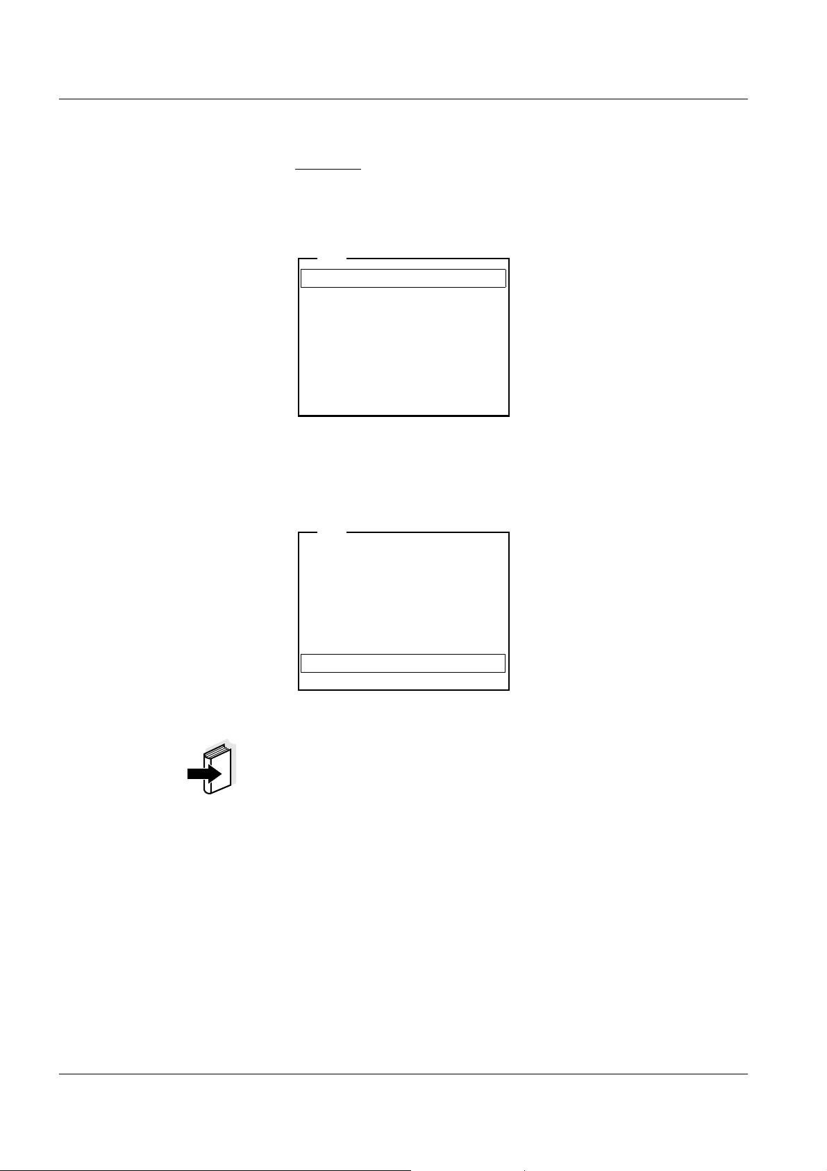
[i] Apply electronic key
or
Press OK (anonym. access).
Anonymous access
User
[i] Identification successfull
[i]USER ID = 9876543210
Register USER ID
USER ID: 1234567890
Erase
Output to RS232/USB
Continue
User
only with administrator login
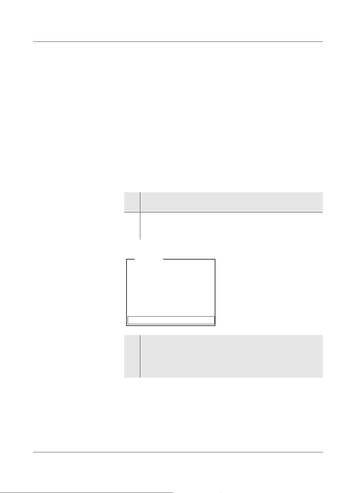
4 Operation
4.1 Switch the meter on and off
Switching on
1 Press the <On/Off> key.
The display shows the meter designation and software version.
Subsequently, the access control display appears.
2 Start anonymous access with <MENU/OK>.
The meter switches to the measuring mode.
or
Place the electronic key on the read field and leave it there for
approx. 2 seconds until the key has been recognized.
The display shows the USER ID that was read.
Switching off
ba75576e05 11/2013
3 Confirm the displayed data with <MENU/OK>.
The meter switches to the measuring mode.
1 Press the <On/Off> key.
The meter is switched off.
19
Page 20

Operation ProLab 1000
4.2 General operating principles
This section contains basic information on the operation of the
ProLab 1000.
Operating elements,
display
Operating modes,
navigation
An overview of the operating elements and the display is given on
page 8 and page 9.
An overview of the operating modes and navigation of the ProLab 1000
is given on page 20 and page 21.
4.2.1 Operating modes
The meter has the following operating modes:
Measuring
Measurement data of the connected sensor appears in the
measured value display
Calibration
The course of a calibration with calibration information, functions
and settings is displayed
Storage in memory
The meter stores measuring data automatically or manually
Transmitting data
The meter transmits measuring data and calibration records to the
serial interface automatically or manually.
Setting
The system menu or a sensor menu with submenus, settings and
functions is displayed
20
ba75576e05 11/2013
Page 21
ProLab 1000 Operation
General
Measurement
Interface
Clock function
Service information
Reset
System
Language: English
Beep
: On
Illumination
: On
Contrast
: 48 %
System
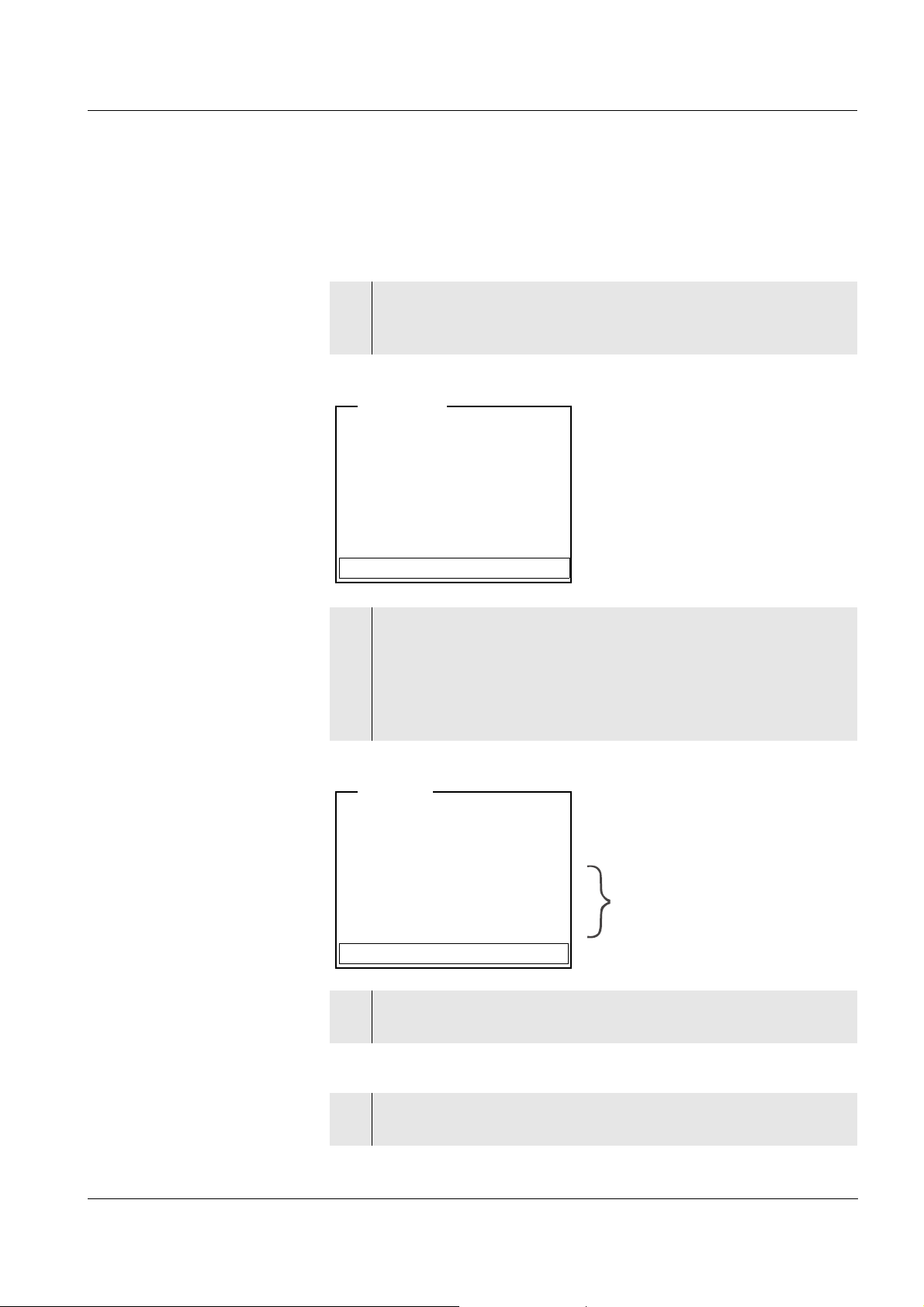
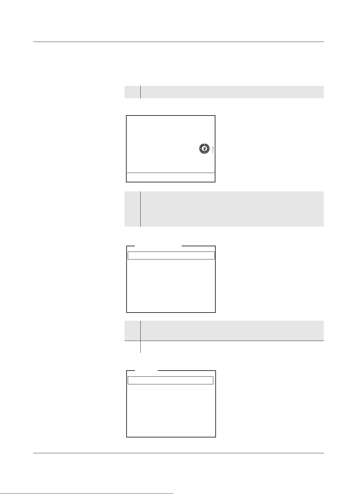
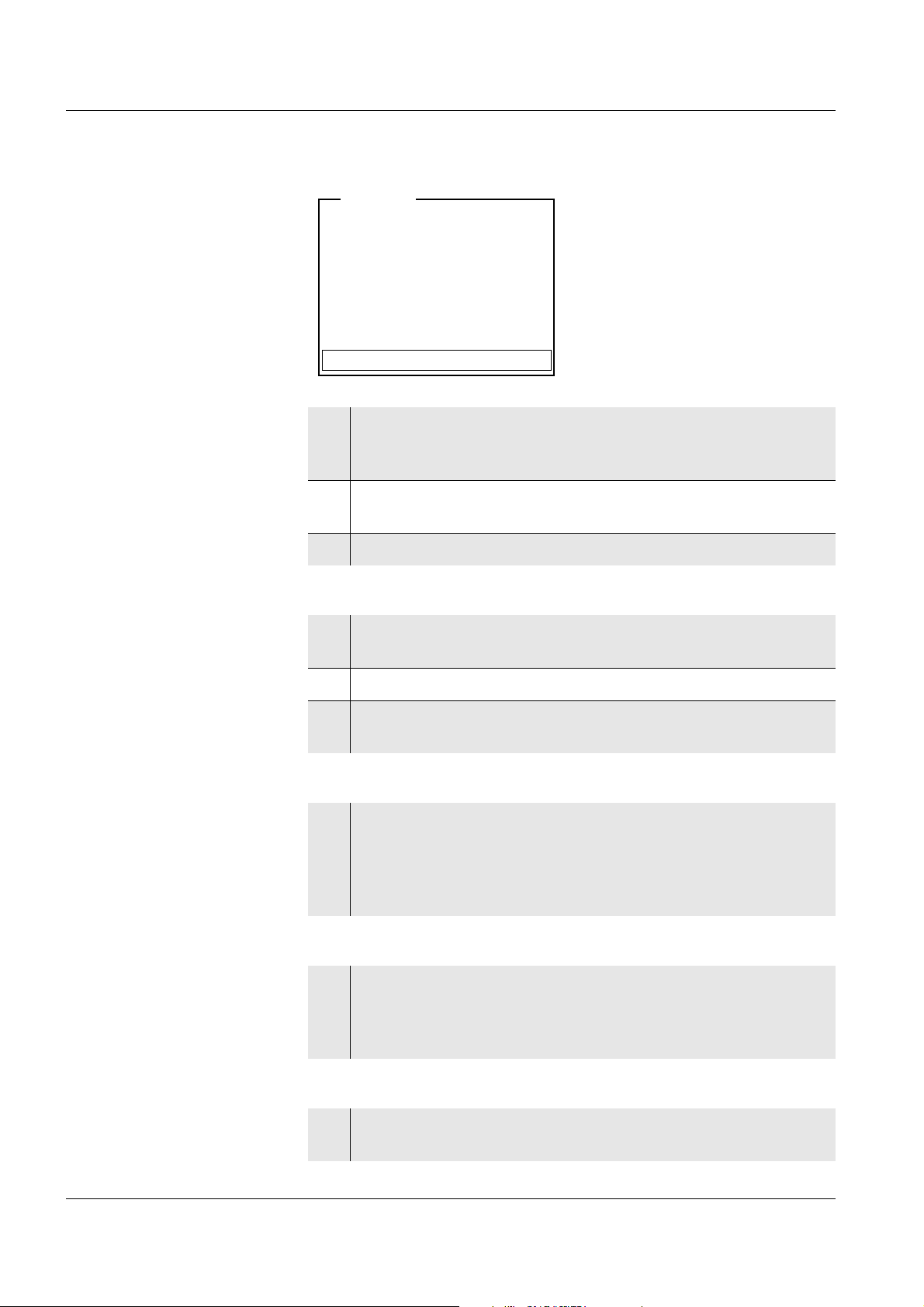
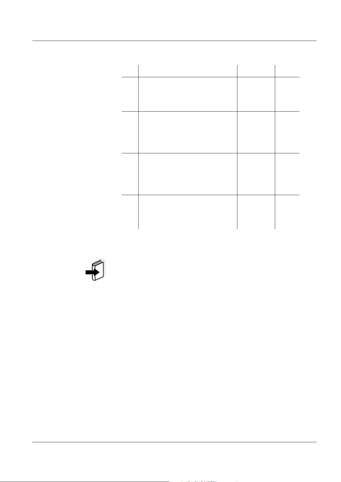
4.2.2 Navigation
Measured value display In the measured value display, you can
open the relevant measuring menu with <MENU/OK>.
open the system menu with the sensor-independent settings with
<MENU/OK
_>.
change the display in the selected measuring window (e. g. pH <−>
mV) by pressing <MODE>.
Menus and dialogs The menus for settings and dialogs contain further submenus. The
selection is made with the <▲><▼> keys. The current selection is
displayed in a frame.
Submenus
The name of the submenu is displayed at the upper edge of the
frame. Submenus are opened by confirming with <MENU/OK>.
Example:
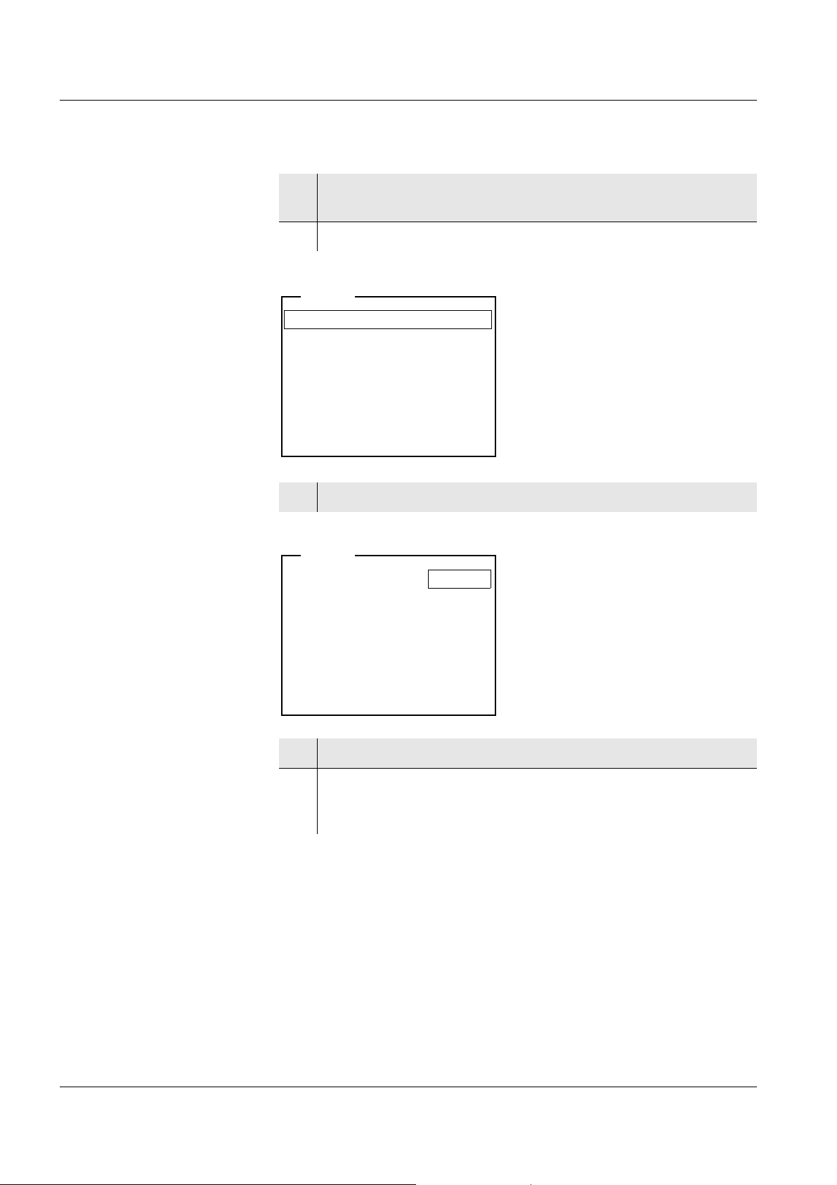
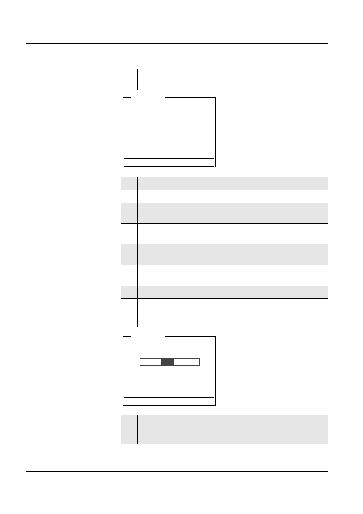
ba75576e05 11/2013
Settings
Settings are indicated by a colon. The current setting is displayed on
the right-hand side. The setting mode is opened with <MENU/OK>.
Subsequently, the setting can be changed with <▲><▼> and
<MENU/OK>.
Example:
21
Page 22
Operation ProLab 1000
Calibration record
Buffer
: NIST/DIN
Calibration interval: 7 d
Unit for zero point pH
Unit for slope
: mV/pH
[i] 2.00 4.01 7.00 10.01
pH
[i] Buffer series NIST/DIN
[i] Immerse sensor in buffer 1
Set temperature: 25 °C
Continue
pH
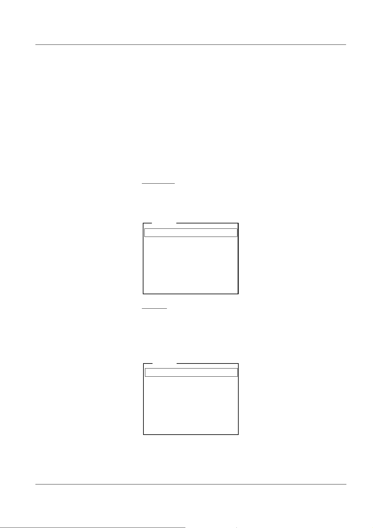
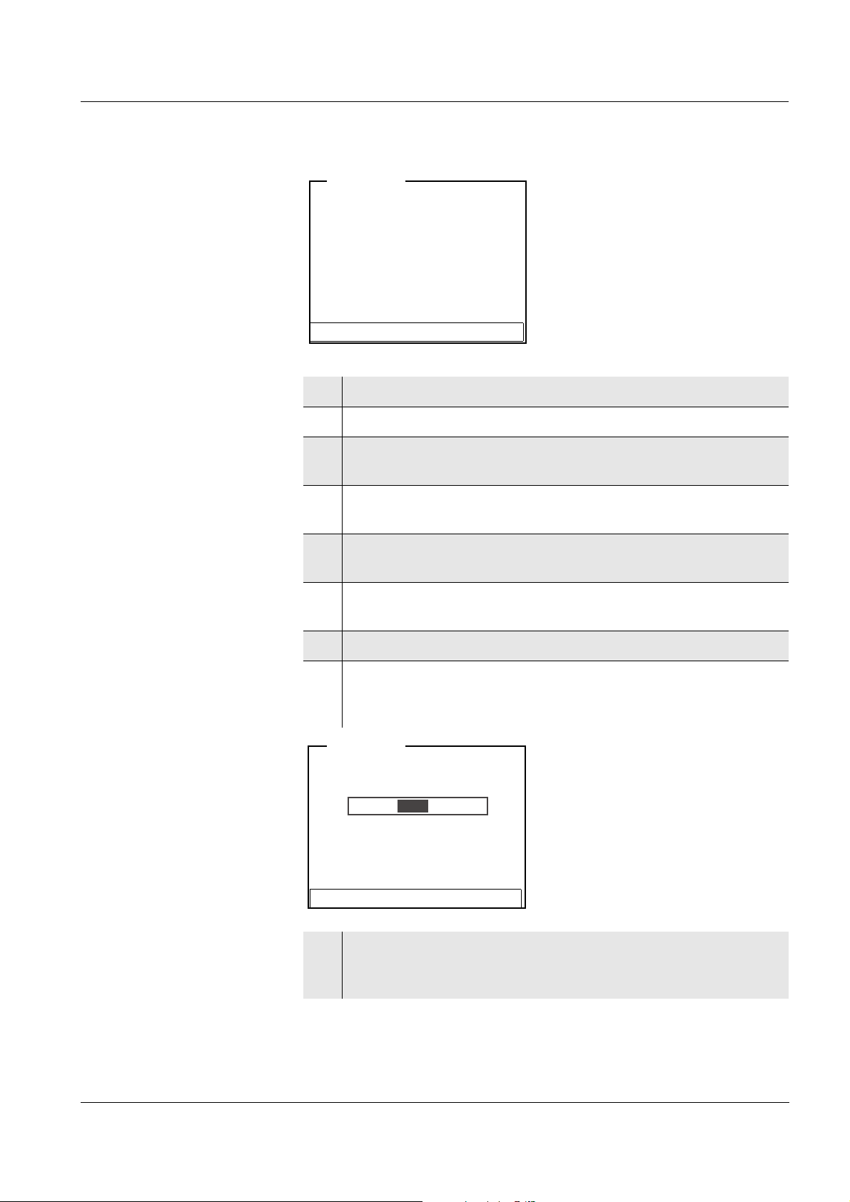
Functions
Functions are indicated by the name of the function. They are
immediately carried out by confirming with <MENU/OK>.
Example: Display the Calibration record function.
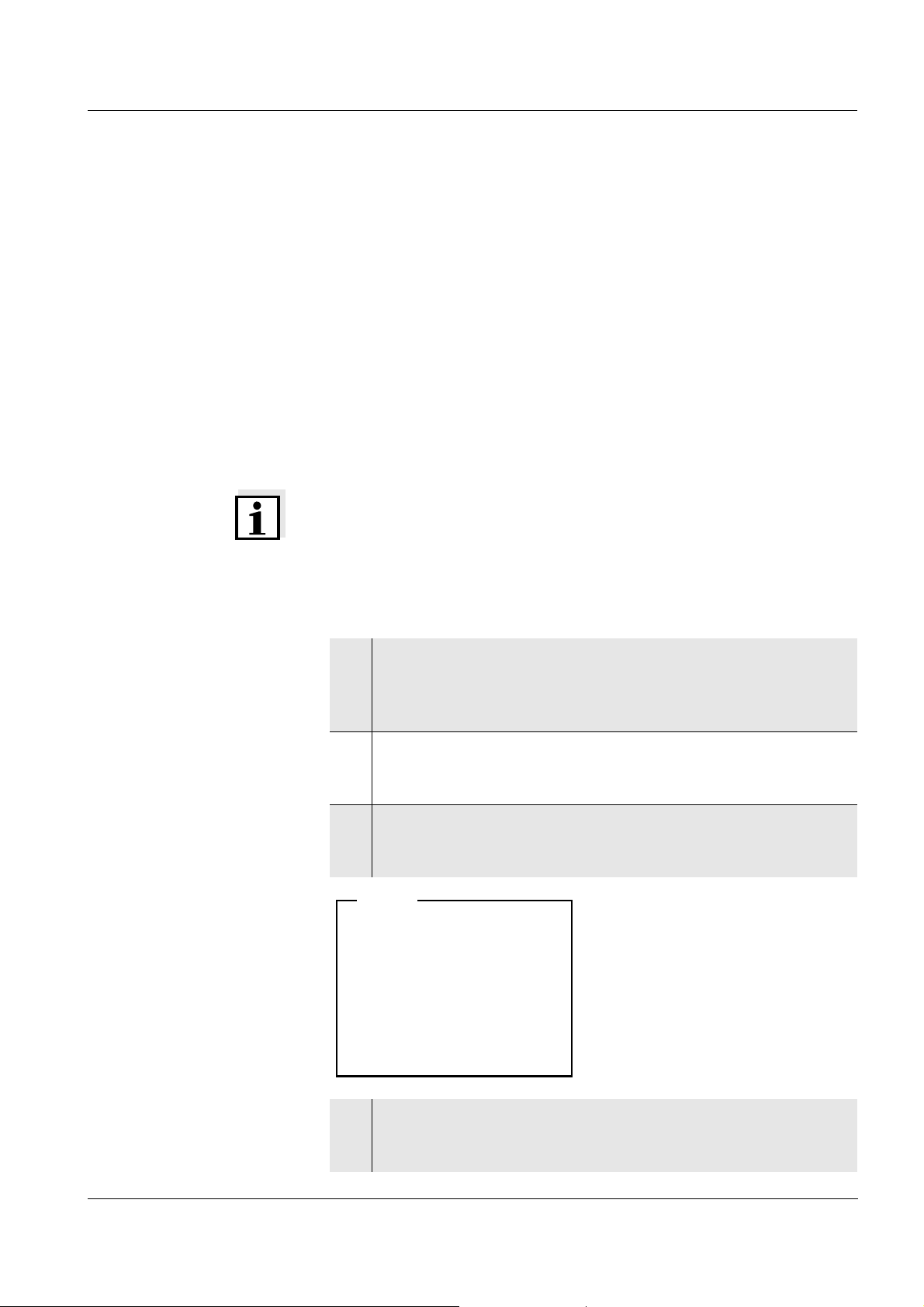
Messages Information or operating instructions are designated by the [i] symbol.
They cannot be selected.
Example:
22
Note
The principles of navigation are explained in the two following sections
by reference of examples:
Setting the language (see page 23)
Setting the date and time (see page 25)
ba75576e05 11/2013
Page 23
ProLab 1000 Operation
pH
7.000
25.0 °C
26.04.06 10:37
Data storage
Display
System
Storage & config
General
Measurement
Interface
Clock function
Service information
Reset
System
4.2.3 Navigation example 1: Setting the language
1 Switch on the meter (see page 19)
2 In the measured value display:
Open the system menu with <MENU/OK
(press for approx. 2 s).
The meter is in the setting mode.
_>
ba75576e05 11/2013
3 Select the System submenu with <▲><▼>.
The current selection is displayed in a frame.
4 Open the System submenu with <MENU/OK>.
23
Page 24
Operation ProLab 1000
Language: English
Beep
: Off
Illumination: On
Contrast
: 48 %
System
Language: English
Beep
: Off
Illumination: On
Contrast
: 48 %
System
5 Select the General submenu with <▲><▼>.
The current selection is displayed in a frame.
6 Open the General
submenu with <MENU/OK>.
7 Open the setting mode for the Language with <MENU/OK>.
24
8 Select the required language with <▲><▼>.
9 Confirm the setting with <MENU/OK>.
The setting becomes active the next time the system menu is
called up.
ba75576e05 11/2013
Page 25
ProLab 1000 Operation
Time: 14:53:40
Date
: 26.04.06
Date format: dd.mm.yy
System
4.2.4 Navigation example 2: Setting the date and time
The meter has a clock with a date function. The date and time are
indicated in the status line of the measured value display. This
indication can be switched off. When storing measured values and
calibrating, the current date and time are automatically stored as well.
The correct setting of the date, time and date format is important for the
following functions and displays:
Current date and time
Calibration date
Identification of stored measured values.
Therefore, check the time at regular intervals.
Note
After a drop of the voltage of the buffer batteries (empty batteries), the
date and time are reset and have to be adjusted again.
Setting the date, time
and date format
The data format can be switched from the display of day, month, year
(dd.mm.yy) to the display of month, day, year (mm/dd/yy or mm.dd.yy).
1 In the measured value display:
Open the system menu with <MENU/OK
(press for approx. 2 s).
The meter is in the setting mode.
2Using <▲><▼> and <MENU/OK>, select and confirm the
System / Clock function menu.
The setting menu for the date and time appears.
3 Using <▲><▼> and <MENU/OK>, select and confirm the Time
menu.
The seconds are highlighted.
_>
ba75576e05 11/2013
4 Change and confirm the setting with <▲><▼> and <MENU/
OK>.
The minutes are highlighted.
25
Page 26

Operation ProLab 1000
5 Change and confirm the setting with <▲><▼> and <MENU/
OK>.
The hours are highlighted.
6 Change and confirm the setting with <▲><▼> and <MENU/
OK>.
The time is set.
7 If necessary, set the Date and Date format. The setting is made
similarly to that of the time.
8 If necessary, select and set the Date with <▲><▼> and
<MENU/OK>.
9 To make further settings, switch to the next higher menu level
with <ESC>.
or
Switch to the measured value display with <MODE>.
The meter is in the measuring mode.
26
ba75576e05 11/2013
Page 27
ProLab 1000 Operation
[i] Apply electronic key
or
Press OK (anonym. access).
Anonymous access
User
4.3 Access control
When the meter is delivered, only the enclosed electronic administrator
key has an access authorization for the meter.
The administrator can set up access authorizations for electronic keys
(see below).
Anonymous access (USER ID: 0) is always possible.
4.3.1 Administrating access authorizations
The ProLab 1000 provides basic functions to administrate access
authorizations. The administrator can set up, erase and display access
authorizations. The administrating functions are available to the
administrator immediately after registration only.
1 When the meter is switched on:
Switch off the meter with <On/Off>.
2 Press the <On/Off> key.
The display shows the meter designation and software version.
Subsequently, the access control display appears.
3 Place the electronic administrator key on the read field and
leave it there for approx. 2 seconds until the key has been
recognized..
The USER ID and the functions for access control are
displayed.
ba75576e05 11/2013
27
Page 28
Operation ProLab 1000
[i] Identification successfull
[i]USER ID = 9876543210
Register USER ID
USER ID: 1234567890
Erase
Output to RS232/USB
Continue
User
Adding new USER IDs
Displaying registered
USER IDs
Erasing a registered
USER ID
4 Using <▲><▼> and <MENU/OK>, select and confirm the
menu item, Register USER ID.
An info text for registration is displayed.
5 Place the electronic key on the reader field.
The USER ID is displayed and registered.
6 Use <MENU/OK> to complete the registration.
7 Using <▲><▼> and <MENU/OK>, select and confirm the
USER ID menu item.
8 Using <▲><▼>, display the registered USER IDs individually.
9 If necessary (e.g. for deleting), confirm a USER ID with
<MENU/OK>.
10 Using <▲><▼> and <MENU/OK>, select and confirm the
Erase menu item.
A safety query appears. After confirming the erasure, the access authorization for the currently displayed key number is
erased.
Outputting a list of the
registered USER IDs
28
Switching to the
measuring mode
11 Using <▲><▼> and <MENU/OK>, select and confirm the
menu item, Output to RS232/USB.
The list of all key numbers with access authorization is
downloaded to the interface.
12 Confirm the data with <MENU/OK>.
The meter switches to the measuring mode.
ba75576e05 11/2013
Page 29
ProLab 1000 Operation
4.3.2 Lost your electronic key?
Without an electronic key with access authorization, anonymous
access is possible only: (USER ID 0).
Electronic key Keys for additional users are available from SI Analytics GmbH.
The access authorization for new keys is set up by the administrator
(see page 27).
Electronic administrator
key
Activating the lock
If the electronic administrator key is lost, the access authorization for a
new electronic administrator key can be set up in the factory only.
The addresses and telephone numbers of SI Analytics GmbH are given
on the cover of this operating manual.
4.3.3 Lock
The activated lock prevents the inadvertent usage of the meter or
registered USER ID during running operation.
The lock can only can only be released with the currently registered
electronic key or the administrator key.
Note
The lock can only be activated in the measuring mode of operation.
With anonymous access (USER ID: 0), the lock function is not
available.
1 If necessary, switch to the measuring mode with <MODE>.
2Use <MODE
The registered USER ID is locked against inadvertent use.
_> to activate the lock.
Releasing the lock
ba75576e05 11/2013
1 Press any key.
2 Place the registered electronic key or administrator key on the
reader field.
Place the registered electronic user key or administrator key on
the read field and leave it there for approx. 2 seconds until the
key has been recognized.
The lock is released.
29
Page 30
Operation ProLab 1000
4.4 System settings (system menu)
The system menu comprises the following settings:
Data storage (see page 30)
Display (see page 30)
System (see page 31).
4.4.1 Data storage
This menu contains all functions to display, edit and erase stored
measured values and calibration records.
Note
Detailed information on the data storage functions of the ProLab 1000
is given on page 61.
4.4.2 Display
With the aid of the Display submenu, you can modify the measured
value display to meet your requirements. When doing so, you can
display or hide the following elements:
Date indication in the status line
Time indication in the status line
Settings In the measured value display, open the system menu with <MENU/
OK
_>. After completing the settings, switch to the measured value
display with <MODE>.
Menu item Setting Description
Display / Time: On
Off
Display / Date: On
Off
Display of the time in the system
status line
Display of the date in the system
status line
30
ba75576e05 11/2013
Page 31

ProLab 1000 Operation
4.4.3 System
Overview The following sensor-independent meter features can be adjusted in
the system menu/System and its submenus:
Menu language
Beep on keystroke
Display illumination
Display contrast
Unit of the temperature display
Data interface
Clock and date function
Function to reset all sensor-independent system settings to the
default condition
Settings In the measured value display, open the system menu with <MENU/
OK
_>. After completing the settings, switch to the measured value
display with <MODE>.
Menu item Setting Description
System / General /
Language
System / General /
Beep
System / General /
Illumination
System / General /
Contrast
System /
Measurement /
Temperature unit
System /
Measurement /
Stability control
Deutsch
English
(further)
On
Off
On
Off
0 ... 100 % Change the display contrast
°C
°F
Auto
Off
Select the menu language
Switch on/off the beep on
keystroke
Switch the display illumination
on/off
Temperature unit, degrees
Celsius or degrees Fahrenheit.
All temperatures are displayed
with the selected unit.
Switch on or off the automatic
Stability control (see page 32).
ba75576e05 11/2013
System / Interface /
Baud rate
1200, 2400,
4800, 9600,
19200
Baud rate of the data interface
31
Page 32

Operation ProLab 1000
Menu item Setting Description
System / Interface /
Output format
ASCII
CSV
Output format for data
transmission
For details, see page 71
System / Interface /
Output header
System /Clock
function
Time
Date
The header is output to the
interface in csv format.
Settings of time and date.
For details, see page 25
Date format
System /Service
information
Meter information:
Series number and software
version
System /Reset - Resets the system settings to
the default values.
For details, see page 75
4.4.4 Automatic Stability control
The automatic Stability control function continuously checks the
stability of the measurement signal. The stability has a considerable
impact on the reproducibility of measured values.
You can activate or switch off the automatic Stability control function
(see page 31).
The automatic Stability control function is carried out:
as soon as the measured value is outside the allowed stability range
when you switch over between the measured parameters with
<MODE>.
In this case, the measured parameter flashes on the display.
32
ba75576e05 11/2013
Page 33

ProLab 1000 Operation
4.5 pH value / ORP voltage
4.5.1 General information
You can measure the following variables:
pH value [ ]
ORP [mV]
CAUTION
When connecting an earthed PC/printer, measurements cannot be
performed in earthed media as incorrect values would result. The
RS232 and USB interfaces are not galvanically isolated.
Temperature
measurement
For reproducible pH measurements, it is essential to measure the
temperature of the test sample.
You have the following options to measure the temperature:
Automatic measurement of the temperature by the temperature
sensor (NTC30 or Pt1000) integrated in electrode.
Measurement by an external temperature sensor.
Manual determination and input of the temperature.
The display of the temperature indicates the active temperature
measuring mode:
Temperature
sensor
Resolution of the
temp. display
Mode
yes 0.1 °C Automatic
with temperature sensor
- 1°C Manual
Preparatory activities Perform the following preparatory activities when you want to measure:
ba75576e05 11/2013
1 Connect a pH or ORP electrode to the meter.
2 If necessary, select the pH or mV display with <MODE>.
3 Adjust the temperature of the solutions and measure the
current temperature if the measurement is made without a
temperature sensor.
4 Calibrate or check the meter with the electrode.
33
Page 34

Operation ProLab 1000
pH
6.949
24.8 °C
26.04.06 10:37
4.5.2 Measuring the pH value
1 Perform the preparatory activities (see page 33).
2 Immerse the pH electrode in the test sample.
3 Select the pH or mV display with <MODE>.
Stability control The Stability control function checks the stability of the measurement
signal. The stability has a considerable impact on the reproducibility of
measured values. The display of the measured parameter flashes until
a stable measured value is available.
Independent of the setting for automatic Stability control (see page 32)
in the System menu, you can start the Stability control function
manually at any time.
1 If necessary, select the displayed measured value with
<MODE>.
2 Freeze the measured value with <SC>.
In the status line, [SC] is displayed.
3 With <MENU/OK> activate the Stability control function.
[SC] flashes while the stability control is active.
As soon as a stable measured value is recognized, the current
measurement data is downloaded to the interface.
Measurement data meeting the criterion for stability control is
marked by SC.
Note
You can terminate prematurely the Stability control function with
<MENU/OK> manually at any time. If the Stability control function is
terminated prematurely, the current measurement data is not
downloaded to the interface.
34
ba75576e05 11/2013
Page 35

ProLab 1000 Operation
4 Using <SC> or <MODE>, release the frozen measured value.
The [SC] status display disappears. The display switches to the
previous indication.
Criteria With identical measurement conditions, the following applies:
Measured
Reproducibility Response time
parameter
pH value Better than 0.01 > 15 seconds
ba75576e05 11/2013
35
Page 36

Operation ProLab 1000
U
157.0 mV
24.8 °C
26.04.06 10:37
4.5.3 Measuring the ORP
Note
ORP electrodes are not calibrated. However, you can check ORP
electrodes using a test solution.
1 Perform the preparatory activities (see page 33).
2 Immerse the ORP electrode in the test sample.
3 Select the mV display with <MODE>.
Stability control The Stability control function checks the stability of the measurement
signal. The stability has a considerable impact on the reproducibility of
measured values. The display of the measured parameter flashes until
a stable measured value is available.
Independent of the setting for automatic Stability control (see page 32)
in the System menu, you can start the Stability control function
manually at any time.
1 If necessary, select the displayed measured value with
<MODE>.
2 Freeze the measured value with <SC>.
In the status line, [SC] is displayed.
3 With <MENU/OK> activate the Stability control function.
[SC] flashes while the stability control is active.
As soon as a stable measured value is recognized, the current
measurement data is downloaded to the interface.
Measurement data meeting the criterion for stability control is
marked by SC.
36
Note
You can terminate prematurely the Stability control function with
<MENU/OK> manually at any time. If the Stability control function is
terminated prematurely, the current measurement data is not
downloaded to the interface.
ba75576e05 11/2013
Page 37

ProLab 1000 Operation
4 Using <SC> or <MODE>, release the frozen measured value.
The [SC] status display disappears. The display switches to the
previous indication.
Criteria With identical measurement conditions, the following applies:
Measured
Reproducibility Response time
parameter
ORP voltage better than 0.3 mV > 15 seconds
ba75576e05 11/2013
37
Page 38

Operation ProLab 1000
4.5.4 Settings for pH and ORP measurements
Overview The following settings are possible for pH and ORP measurements:
Resolution
Calibration interval
Buffers for calibration
Unit for zero point
Unit for slope
Calibration record (display)
Calibration history
Settings The settings are made in the measuring menu of the pH/ORP
measurement. To open it, activate the relevant measuring window in
the measured value display and press <MENU/OK>. After completing
the settings, switch to the measured value display with <MODE>.
Menu item Possible setting Description
Calibration /
Calibration record
- Displays the calibration
record of the last
calibration.
Calibration /
Calibration history
- Displays the calibration
history of the last
calibrations.
Calibration /Buffer NIST/DIN
TEC
...
Calibration /
1 ... 999 d Calibration interval for the
Calibration interval
Buffer sets to be used for
pH calibration (see
page 40).
pH electrode (in days).
The meter reminds you to
calibrate regularly by the
flashing CalClock in the
measuring window.
Calibration /Unit for
zero point
Calibration /Unit for
slope
mV
pH
mV/pH
%
Unit for the zero point.
Unit of the slope.
The % display refers to
the Nernst slope of
-59.16 mV/pH
([determined slope/Nernst
slope] x 100).
38
ba75576e05 11/2013
Page 39

ProLab 1000 Operation
Menu item Possible setting Description
Man. temperature -20 ... +130 °C Entry of the manually
determined temperature.
For measurements
without temperature
sensor only.
Reset - Resets all sensor settings
to the delivery condition
(see page 74).
High resolution pH On
Off
High resolution mV On
Off
Resolution of the pH
display:
On = 0.001
Off = 0.01
Resolution of the mV
display:
On = 0.1 mV
Off = 1 mV
ba75576e05 11/2013
39
Page 40

Operation ProLab 1000
4.5.5 pH calibration
Why calibrate? pH electrodes age. This changes the zero point (asymmetry) and slope
of the pH electrode. As a result, an inexact measured value is
displayed. Calibration determines the current values of the zero point
and slope of the electrode and stores them.
Thus, you should calibrate at regular intervals.
When do you have to
calibrate?
Buffer sets for
calibration
After connecting a non-ID electrode
If the CalClock has expired and flashes
You can use the buffer sets quoted in the table for an automatic
calibration. The pH values are valid for the specified temperature
values. The temperature dependence of the pH values is taken into
account during the calibration.
No. Buffer set * pH values at
1 DIN buffers according to DIN
19266 and NIST Traceable
Buffers
1.679
4.006
6.865
25 °C
9.180
12.454
2 Technical buffers 2.000
25 °C
4.010
7.000
10.011
3 Merck1* 4.000
20°C
7.000
9.000
40
4 Merck2 * 1.000
6.000
8.000
13.000
5 Merck3 * 4.660
6.880
9.220
6 Merck4 * 2,000
4,000
7,000
10,000
7 Merck5 * 4,010
7,000
10,000
ba75576e05 11/2013
20°C
20°C
20 °C
25 °C
Page 41

ProLab 1000 Operation
No. Buffer set * pH values at
8 DIN 19267 1.090
4.650
6.790
9.230
9 Mettler US * 1.679
4.003
7.002
10.013
10 Mettler EU * 1.995
4.005
7.002
9.208
11 Fisher 1* 2.007
4.002
7.004
10.002
12 Fluka BS * 4.006
6.984
8.957
13 Radiometer * 1.678
4.005
7.000
9.180
25 °C
25 °C
25 °C
25 °C
25 °C
25 °C
14 Baker * 4.006
6.991
10.008
15 Metrohm * 3.996
7.003
8.999
16 Beckman * 4.005
7.005
10.013
17 Hamilton DC * 4.005
7.002
10.013
18 Precisa * 3.996
7.003
8.999
25 °C
25 °C
25 °C
25 °C
25 °C
ba75576e05 11/2013
41
Page 42

Operation ProLab 1000
No. Buffer set * pH values at
8 DIN 19267 1.090
4.650
6.790
9.230
9 Mettler US * 1.679
4.003
7.002
10.013
10 Mettler EU * 1.995
4.005
7.002
9.208
11 Fisher 1* 2.007
4.002
7.004
10.002
12 Fluka BS * 4.006
6.984
8.957
13 Radiometer * 1.678
4.005
7.000
9.180
25 °C
25 °C
25 °C
25 °C
25 °C
25 °C
14 Baker * 4.006
6.991
10.008
15 Metrohm * 3.996
7.003
8.999
16 Beckman * 4.005
7.005
10.013
17 Hamilton DC * 4.005
7.002
10.013
18 Precisa * 3.996
7.003
8.999
25 °C
25 °C
25 °C
25 °C
25 °C
42
ba75576e05 11/2013
Page 43
ProLab 1000 Operation
No. Buffer set * pH values at
19 Reagecon TEC * 2,000
25 °C
4,010
7,000
10,000
20 Reagecon 20 * 2,000
20 °C
4,000
7,000
10,000
13,000
21 Reagecon 25 * 2,000
25 °C
4,000
7,000
10,000
13,000
22 Riedel-de Haen * 2,000
20 °C
4,000
7,000
10,000
* Brand names or trade names are trademarks of their respective
owners protected by law (see page 91).
Note
The buffers are selected in the sensor menu (Buffer setting, see
page 38).
ba75576e05 11/2013
43
Page 44

Operation ProLab 1000
Calibration points Calibration can be performed using one to five buffer solutions in any
order (single-point to five-point calibration). The meter determines the
following values and calculates the calibration line as follows:
Determined
Displayed calibration data
values
1-point ASY Zero point = ASY
Slope = Nernst slope
(-59.16 mV/pH at 25 °C)
2-point ASY
SLO
3-point to
5-point
ASY
SLO
Zero point = ASY
Slope = SLO
Zero point = ASY
Slope = SLO
The calibration line is calculated
by linear regression.
Note
You can display the slope in the units, mV/pH or % (see page 31).
Stability control The calibration procedure automatically activates the stability control
function.
The current measurement with stability control can be terminated at
any time (accepting the current value).
Calibration record When finishing a calibration, the new calibration values are displayed
Display of calibration
data and download to
interface
44
as an informative message ([i] symbol) first. Then you can decide
whether you want to take over these values of the new calibration or
whether you want to continue measuring with the old calibration data.
After accepting the new calibration values the calibration record is
displayed.
You can have the data of the last calibration displayed (see page 68).
Subsequently, you can transmit the displayed calibration data to the
interface, e. g. to a printer or PC, with the <PRINT> key.
Note
The calibration record is automatically transmitted to the interface after
calibrating.
ba75576e05 11/2013
Page 45

ProLab 1000 Operation
Printing date 26.04.06 16:13
ProLab 1000
Ser. no. 06249876
USER ID: 1234567890
CALIBRATION pH
Calibration date 20.04.06 10:14:03
A 161 1M DIN-ID
Ser. no. A062498765
USER ID: 1234567890
Cal. interval 7 d
NIST/DIN
Buffer 1 6.86
Buffer 2 9.18
Voltage 1 7.2 mV 26.3 °C
Voltage 2 -171 mV 26.3 °C
Slope -59.2 mV/pH
Zero point -0.5 mV
Sensor +++
Sample record:
Calibration evaluation After calibrating, the meter automatically evaluates the calibration. The
zero point and slope are evaluated separately. The worse evaluation of
both is taken into account. The evaluation appears on the display and
in the calibration record.
Preparatory activities Perform the following preparatory activities when you want to calibrate:
Display Calibration
record
+++ -18 ... +18 -60.5 ... -57.5
++ -22 ... + 22 -57.5 ... -56
+ -26 ... +26 -61 ... -60.5
- -30 ... +30 -62 ... -61
Clean the electrode according
to the sensor operating manual
CalError CalError
Eliminate the error according to
chapter 6 W
HAT TO DO IF...
(page 79)
Zero point [mV] Slope
[mV/pH]
or
-56 ... -55
or
-55 ... -50
< -30 or
> 30
... -62 or
... -50
ba75576e05 11/2013
45
Page 46

Operation ProLab 1000
1 Connect a pH electrode to the meter.
The pH measuring window is displayed.
2 Keep the buffer solutions ready. Adjust the temperature of the
buffer solutions, or measure the current temperature, if you
measure without a temperature sensor.
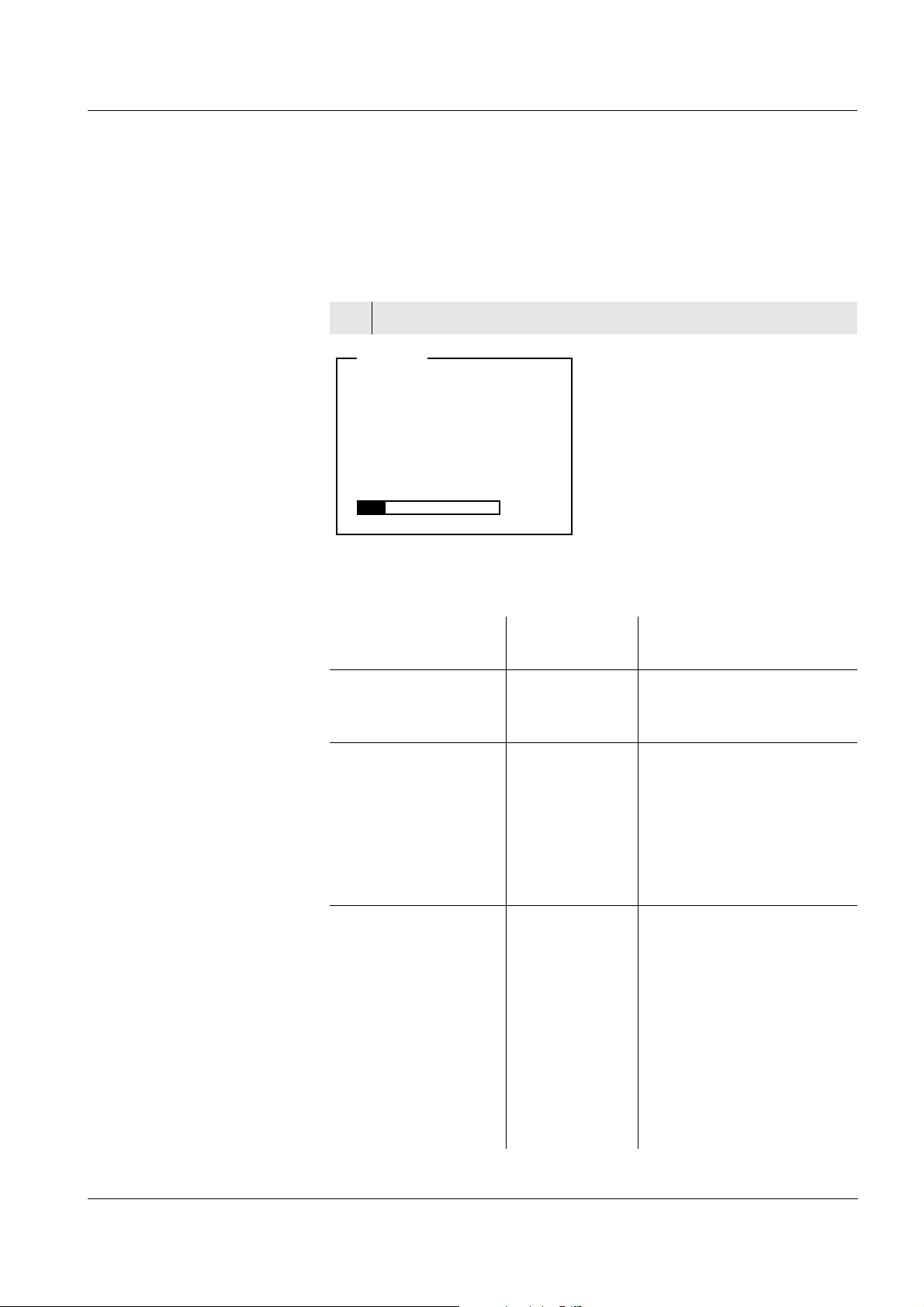
4.5.6 Calibration interval
The calibration interval and calibration evaluation are indicated on the
display as the CalClock.
CalClock
Setting the calibration
interval
The remaining time of the calibration interval is indicated by the
segmented ring around the calibration evaluation. This segmented ring
reminds you to calibrate regularly.
After the specified calibration interval has expired the outside circle of
the CalClock flashes. It is still possible to measure.
Note
To ensure the high measuring accuracy of the measuring system,
calibrate after the calibration interval has expired.
The calibration interval is set to 7 (d7) days in the factory.
You can change the interval (1 ... 999 days):
1 Open the menu for measurement settings with <MENU/OK>.
2In the Calibration / Calibration interval menu, set the calibration
interval with <▲><▼>.
3 Confirm the setting with <MENU/OK>.
4 Exit the menu with <MODE>.
46
ba75576e05 11/2013
Page 47

ProLab 1000 Operation
[i] Buffer series NIST/DIN
[i] Immerse sensor in buffer 1
Continue
pH <CAL>
[i] Buffer value = 6.865
[i] U = 3.0 mV
[i] Temperature =
24.8 °C
Terminate stability control
Recognized nominal buffer
value (referring to 25 °C)
Current electrode voltage
Current temperature value
pH <CAL>
4.5.7 Calibrating
Make sure the Buffer setting is correctly set in the sensor menu (see
page 38).
Use any one to five buffer solutions of the selected buffer set in
ascending or descending order.
The NIST/DIN calibration is described below. With other buffer sets,
other nominal buffer values are displayed. Apart from that, the
procedure is identical.
1 Press <MODE> to select the measured parameter pH or mV in
the measured value display.
2 Start the calibration with <CAL>.
The calibration display appears.
3 Immerse the electrode in buffer solution 1.
4 If the Set temperature menu item appears, measure and enter
the temperature of the buffer manually (measurement without
temperature sensor).
5 Select Continue with <▲><▼> and press <MENU/OK>. The
buffer is measured.
The measured value is checked for stability (Stability control).
ba75576e05 11/2013
47
Page 48

Operation ProLab 1000
[i] Buffer series NIST/DIN
[i] Immerse sensor in buffer 2
Exit with one point calibration
Continue
pH <CAL>
6 Wait for the end of the measurement with Stability control or
accept the calibration value with <MENU/OK>.
The calibration display for the next buffer appears.
7 For single-point calibration, select Exit with one point
calibration with <▲><▼> and confirm with <MENU/OK>.
The calibration is completed as a single-point calibration.
The new calibration values are displayed as a message ([i]).
You have the following options:
Accept the new calibration values with <MENU/OK>.
Subsequently, the calibration record is displayed and
downloaded to the interface at the same time.
Continuing with two-
point calibration
(Buffer: NIST/DIN)
To switch to the measured value display without
accepting
the new calibration values, press <MODE> or <ESC>.
Note
For single-point calibration, the meter uses the Nernst slope
(-59.16 mV/pH at 25 °C) and determines the zero point of the
electrode.
8 Thoroughly rinse the electrode with distilled water.
9 Immerse the electrode in buffer solution 2.
10 If the Set temperature menu item appears, measure and enter
the temperature of the buffer manually (measurement without
temperature sensor).
11 Select Continue with <▲><▼> and press <MENU/OK>. The
buffer is measured.
The measured value is checked for stability (Stability control).
48
ba75576e05 11/2013
Page 49

ProLab 1000 Operation
[i] Buffer value = 9.18
[i] U = -167.0 mV
[i] Temperature =
24.8 °C
Terminate stability control
pH <CAL>
[i] Buffer series NIST/DIN
[i] Immerse sensor in buffer 3
Exit with 2 point calibration
Continue
pH <CAL>
12 Wait for the measurement with stability control to be completed
or Terminate stability control with <MENU/OK> and accept the
calibration value.
The calibration display for the next buffer appears.
Continuing with three-
point to five-point
(Buffer NIST/DIN)
calibration
13 For two-point calibration, select Exit with 2 point calibration with
<▲><▼> and confirm with <MENU/OK>.
The calibration is completed as a two-point calibration.
The new calibration values are displayed as a message ([i]).
You have the following options:
Accept the new calibration values with <MENU/OK>.
Subsequently, the calibration record is displayed and
downloaded to the interface at the same time.
To switch to the measured value display without
accepting
the new calibration values, press <MODE> or <ESC>.
14 Thoroughly rinse the electrode with distilled water.
15 Immerse the electrode in buffer solution 3.
16 If necessary, measure the temperature of buffer 3 manually,
then enter and confirm it with <▲><▼> and <MENU/OK> in the
Set temperature setting.
17 Select Continue with <▲><▼> and press <MENU/OK>. The
buffer is measured.
The measured value is checked for stability (Stability control).
ba75576e05 11/2013
49
Page 50

Operation ProLab 1000
[i] Buffer value = 4.010
[i] U = 184.0 mV
[i] Temperature =
24.8 °C
Terminate with ...
Terminate stability control
pH <CAL>
18 Switch to measurement of the next buffer with <MENU/OK>.
or
When all buffers have been measured, use <▲><▼> to select
the Terminate with ... menu item and confirm with <MENU/
OK>.
The calibration procedure is terminated.
The new calibration values are displayed as a message ([i]).
You have the following options:
Accept the new calibration values with <MENU/OK>.
Subsequently, the calibration record is displayed and
downloaded to the interface at the same time.
To switch to the measured value display without
accepting
the new calibration values, press <MODE> or <ESC>.
Note
After a five-point calibration the calibration procedure is automatically
terminated. The menu item Terminate with ... is not displayed.
Note
The calibration line is calculated by linear regression.
50
ba75576e05 11/2013
Page 51

ProLab 1000 Operation
Double Pt-electrode
Dead stop cable
4.5.8 Measurements with dead stop function
Measurements with dead stop function are normally used for measured
value logging during a manual dead stop titration (e.g. Karl Fischer
titration).
A voltage is present at the dead stop sockets. The voltage value is constant before the end point of the titration is reached.
Even with a small excess of titration solution, a very strong voltage drop
occurs.
Thus the end point of the titration is reached.
Preparatory activities
1 Connect the pH socket and dead stop socket with the dead
stop cable.
2 Connect a double Pt electrode, e.g. type Pt 1400, to the dead
stop sockets of the meter.
ba75576e05 11/2013
3 Immerse the double Pt electrode in the test sample.
4 On the meter, switch to the mV display with <MODE>.
51
Page 52

Operation ProLab 1000
4.6 Ion concentration
4.6.1 General information
Note
Incorrect calibration of ion sensitive electrodes will result in incorrect
measured values. Calibrate regularly before measuring.
CAUTION
When connecting an earthed PC/printer, measurements cannot be
performed in earthed media as incorrect values would result. The
RS232 and USB interfaces are not galvanically isolated.
Temperature
measurement with ISE
measurements
For reproducible measurements of the ion concentration, it is essential
to measure the temperature of the test sample.
You have the following options to measure the temperature:
Measurement by a temperature sensor.
Manual determination and input of the temperature.
The meter recognizes whether a suitable sensor is connected and
automatically switches on the temperature measurement.
The display of the temperature indicates the active temperature
measuring mode:
Temperature
sensor
Resolution of the
temp. display
Mode
- 1°C Manual
yes 0.1 °C Automatic with
temperature sensor
* If this is not required you can unplug the second sensor and enter the
temperature manually.
52
ba75576e05 11/2013
Page 53

ProLab 1000 Operation
ISE
0.157 mg/l
25 °C
Preparatory activities Perform the following preparatory activities when you want to measure:
1 Connect the ISE combination electrode to the meter.
The pH/ISE measuring window is displayed.
2 If necessary, select the ISE display (unit, mg/l) with <MODE>.
3 Measure the temperature of the test sample using a
thermometer.
4 Calibrate or check the meter with the electrode.
Note
While no valid calibration is available, e.g. in the delivery condition,
"Error" appears in the measured value display.
4.6.2 Measuring the ion concentration
1 Perform the preparatory activities according to page 52.
2 Immerse the electrode in the test sample.
Stability control The Stability control function checks the stability of the measurement
signal. The stability has a considerable impact on the reproducibility of
measured values. The display of the measured parameter flashes until
a stable measured value is available.
Independent of the setting for automatic Stability control (see page 32)
in the System menu, you can start the Stability control function
manually at any time.
ba75576e05 11/2013
1 If necessary, select a channel (measured value) with <▲><▼>.
53
Page 54

Operation ProLab 1000
2 Freeze the measured value with <SC>.
The display switches to the display of the selected channel as
necessary.
In the status line, [SC] is displayed.
3 With <MENU/OK> activate the Stability control function.
[SC] flashes while the stability control is active.
As soon as a stable measured value is recognized, the current
measurement data is downloaded to the interface. The
measured values of all channels meeting the criterion for
stability control are marked by SC.
Note
You can terminate prematurely the manual Stability control function
with <MENU/OK> manually at any time. If the manual Stability control
function is terminated prematurely, the current measurement data is
not downloaded to the interface.
Criteria With identical measurement conditions, the following applies:
Temperature while
calibrating and
measuring
Overview The following settings are possible for ISE measurements:
4 Using <SC> or <MODE>, release the frozen measured value.
The [SC] status display disappears. The display switches to the
previous indication.
Measuring signal Reproducibility Response time
Electrode
better than 0.1 mV > 30 seconds
voltage
For precise ISE measurements the temperature difference between
measurement and calibration should not be greater that 2 K. Therefore,
adjust the temperature of the standard and measuring solutions
accordingly. If the temperature difference is greater the [TempErr]
warning appears in the measured value display.
4.6.3Settings for ISE measurements
Calibration record (display)
54
Calibration history
Settings The settings are made in the measuring menu of the ISE
measurement. To open it, activate the relevant measuring window in
the measured value display and press the <MENU/OK> key. After
completing the settings, switch to the measured value display with
<MODE>.
ba75576e05 11/2013
Page 55

ProLab 1000 Operation
Menu item Possible
Description
setting
Calibration /
Calibration record
Calibration /
Calibration history
- Displays the calibration
record of the last calibration.
- Displays the calibration
history of the last calibrations.
Man. temperature -20 ... +130 °C Entry of the manually
determined temperature. For
measurements without
temperature sensor only.
Ion type Ag, Br, Ca, Cd,
Cl, CN, Cu, F,
Selection of the ion type to be
measured
I, K, Na, NO3,
Pb, S, NH3,
NH4, CO2
Unit mol/l, mg/kg,
ppm, %, mg/l
Selection of the unit for the
display of the measurement
result and calibration
standards.
Density 0.001 ... 9.999
g/ml, kg/l
Adjustable density of the test
sample (only with
Unit: mg/kg, ppm, %)
4.6.4 Calibrating for ISE measurements
Why calibrate? Ion-selective electrodes age and are temperature-dependent. This
changes the slope. As a result, an inexact measured value is displayed.
Calibration determines the current value of the slope of the electrode
and stores it in the instrument.
Thus, you should calibrate before each measurement and at regular
intervals.
When to calibrate? Before any measurement if possible
After connecting another ISE electrode
When the CalClock flashes, e. g. after a voltage interruption
Standard solutions Use two to seven different standard solutions. The standard solutions
have to be selected in either increasing or decreasing order.
ba75576e05 11/2013
Note
The unit of the standard solution and measurement result is selected in
the Calibration / Unit menu.
55
Page 56

Operation ProLab 1000
Standard solution (Std 1 - 7) Values [mg/l]
Unit [mg/l] 0.010 ... 500000
Unit [mol/l] 0.100 ... 5000 µmol/l
10.00 ... 5000 mmol/l
Unit [mg/kg] 0.010 ... 500000
Unit [ppm] 0.010 ... 500000
Unit [%] 0.001 ... 50000
Note
The measurement precision is also dependent on the selected
standard solutions. Therefore, the selected standard solutions should
cover the expected value range of the subsequent concentration
measurement.
Temperature while
calibrating and
measuring
For precise ISE measurements the temperature difference between
measurement and calibration should not be greater that 2 K. Therefore,
adjust the temperature of the standard and measuring solutions
accordingly. If the temperature difference is greater the [TempErr]
warning appears in the measured value display.
ISE Cal This is the conventional two-point to seven-point calibration
procedure that uses 2 to 7 freely selectable standard solutions. The
concentration expected in the measurement determines the
concentration of the calibration standards.
Stability control During calibration, the stability control is automatically activated.
The current measurement with stability control can be terminated at
any time (accepting the current value).
Calibration record When finishing a calibration, the new calibration values are displayed
as an informative message ([i] symbol) first. Then you can decide
whether you want to take over these values of the new calibration or
whether you want to continue measuring with the old calibration data.
After accepting the new calibration values the calibration record is
displayed.
Note
Based on the calibration data, the calibration line is determined in
sections according to the Nernst equation modified by Nikolski.
Display of calibration
data and download to
interface
56
You can have the data of the last calibration displayed (see page 68).
Subsequently, you can transmit the displayed calibration data to the
interface, e. g. to a printer or PC, with the <PRINT> key.
ba75576e05 11/2013
Page 57

ProLab 1000 Operation
Printing date 26.04.06 16:13
ProLab 1000
Ser. no. 06249876
USER ID: 1234567890
Calibration ISE
Calibration date 20.04.06 10:14:03
USER ID: 1234567890
Standard 1 0.010 mg/l
Standard 2 0.020 mg/l
Voltage 1 0.0 mV 24.0 °C
Voltage 2 9.0 mV 24.0 °C
Slope 29.9 mV
Sensor +++
Note
The calibration record is automatically transmitted to the interface after
calibrating.
Sample record:
Calibration evaluation After calibrating, the meter automatically evaluates the calibration.
Display Calibration
Magnitude of the slope [mV]
record
+++ 50.0 ... 70.0 or 25.0 ... 35.0
Error Error
Eliminate the error according to
chapter 6 W
HAT TO DO IF...
< 50 or > 70
or
< 25 or > 35
(page 79)
Preparatory activities Perform the following preparatory activities when you want to calibrate:
1 Connect the ISE combination electrode to the meter.
The pH/mV/ISE measuring window is displayed.
2 Keep the standard solutions ready.
3 Measure the temperature of the standard solutions using a
thermometer.
ba75576e05 11/2013
Carrying out an
ISE calibration
Proceed as follows to calibrate the meter:
1 In the measured value display, select the ISE measuring
window with <▲><▼> and <MODE>.
57
Page 58
Operation ProLab 1000
[i] Immerse sensor in std. 1
Set temperature:24 °C
Continue
Set standard: 0.010 mg/l
ISE <CAL>
[i] Standard = 0.010 mg/l
[i] U = 0.5 mV
Terminate stability control
ISE <CAL>
2 Start the calibration with <CAL>.
The calibration display appears.
3 Thoroughly rinse the electrode with distilled water.
4 Immerse the electrode in standard solution 1.
5 Using <▲><▼>, select the Set standard setting and press
<MENU/OK> .
6 Set the concentration of the standard solution with <▲><▼>
and press <MENU/OK>.
7 Measure the temperature of the standard solution using a
thermometer.
8 Select the Set temperature setting with <▲><▼> and press
<MENU/OK>.
9 Set the temperature with <▲><▼> and press <MENU/OK>.
10 Select Continue with <▲><▼> and press <MENU/OK>.
The standard solution is measured.
The measured value is checked for stability (Stability control).
58
11 Wait for the end of the measurement with Stability control or
accept the calibration value with <MENU/OK>.
The calibration display for the next standard solution appears.
ba75576e05 11/2013
Page 59
ProLab 1000 Operation
[i] #1 0.010 mg/l 24 °C
[i] Immerse sensor in std. 2
Set temperature:24 °C
Continue
Set standard: 0.020 mg/l
ISE <CAL>
[i] Standard = 0.020 mg/l
[i] U = 8.4 mV
Terminate stability control
ISE <CAL>
Continuing with two-
point calibration
12 Thoroughly rinse the electrode with distilled water.
13 Immerse the electrode in standard solution 2.
14 Using <▲><▼>, select the Set standard setting and press
<MENU/OK> .
15 Set the concentration of the standard solution with <▲><▼>
and press <MENU/OK>.
16 Measure the temperature of the standard solution using a
thermometer.
17 Select the Set temperature setting with <▲><▼> and press
<MENU/OK>.
18 Set the temperature with <▲><▼> and press <MENU/OK>.
19 Select Continue with <▲><▼> and press <MENU/OK>.
The standard solution is measured.
The measured value is checked for stability (Stability control).
ba75576e05 11/2013
20 Wait for the end of the measurement with Stability control or
accept the calibration value with <MENU/OK>.
The calibration display for the next standard solution appears.
59
Page 60

Operation ProLab 1000
[i] #2 0.020 mg/l 24 °C
[i] Immerse sensor in std. 3
Set temperature: 24 °C
Continue
Exit with 2 point calibration
Set standard: 0.050 mg/l
ISE <CAL>
21 For two-point calibration, select Exit with 2 point calibration with
<▲><▼> and confirm with <MENU/OK>.
The calibration is completed as a two-point calibration.
The new calibration values are displayed as a message ([i]).
You have the following options:
Accept the new calibration values with <MENU/OK>.
Subsequently, the calibration record is displayed and
downloaded to the interface at the same time.
Continuing with three-
point to seven-point
calibration
To switch to the measured value display without
accepting
the new calibration values, press <MODE> or <ESC>.
Repeat the steps 12 to 20 in the same way with the third and further
standard solutions as necessary. After finishing the last calibration
step, the new calibration values are displayed as a message ([i]).
You have the following options:
Accept the new calibration values with <MENU/OK>. Subsequently,
the calibration record is displayed and downloaded to the interface
at the same time.
To switch to the measured value display without
accepting the new
calibration values, press <MODE> or <ESC>.
60
ba75576e05 11/2013
Page 61

ProLab 1000 Operation
4.7 Storage
You can transmit measured values (datasets) to the data storage in two
ways:
Manual storage (see page 62)
Automatic storage at intervals (see page 63)
Each storage process transmits the current dataset to the interface at
the same time.
Measurement dataset A complete dataset consists of:
Date/time
USER ID
Meter designation with series number
SENSOR ID
– Sensor designation
– Sensor series number
SAMPLE ID
Measured value of the connected sensor
Measured temperature value of the connected sensor
Info on stability control: SC appears with the measured value if the
Stability control criterion was met while storing (stable measured
value). Otherwise, there is no SC display.
Storage locations The meter has separate data storages for manually stored measured
values and automatically stored measured values.
Storage Maximum number of datasets
Manual storage 329
Automatic storage 5628
ba75576e05 11/2013
61
Page 62

Operation ProLab 1000
- 26.04.2006 11:24:16
- pH 7.000 24.8 °C SC
SAMPLE ID:1
Continue
<STO> 1 of 646
Data storage full. Erase?
Yes
No
Warning
4.7.1 Manual storage
Proceed as follows to transmit to the data storage and simultaneously
download to the interface a measurement dataset:
1 Open the menu for manual storage with <STO>.
2 If necessary, use <▲><▼> and <MENU/OK> to change and
confirm the SAMPLE ID (1 ... 999).
The dataset is stored. The meter switches to the measured
value display.
If the data storage is full The following window appears if all storage locations are occupied:
You have the following options:
To erase the entire data storage, confirm Yes.
To cancel the storage process and switch to the measured value
display, confirm No. Then you can e.g. transmit the stored data to a
PC (see page 65) and subsequently erase the storage (see
page 68).
62
ba75576e05 11/2013
Page 63
ProLab 1000 Operation
SAMPLE ID 1
Interval 30 s
Duration 180 min
Continue
00d03h00min 00d15h
34min
<STO_>
4.7.2 Automatic storage at intervals
The storage interval (Interval) determines the chronological interval
between automatic storage processes. Each storage process transmits
the current dataset to the interface at the same time.
Configuring the
automatic storage
function
1 Open the menu for automatic storage with <STO_>.
Settings You can configure the automatic storage function with the following
ba75576e05 11/2013
settings:
Menu item Possible
Description
setting
SAMPLE ID 1 ... 999 Determine the sample
designation for the series
of datasets.
Interval 1, 5 s, 10 s,
30 s, 1 min,
5 min, 10 min,
15 min,
30 min, 60 min
Storage interval.
The lower limit of the
storage interval can be
restricted by the number of
free storage locations.
The upper limit is restricted
by the storage duration.
Duration 1 min ... x min Storage duration.
Specifies after which time
the automatic storage
should be terminated.
The lower limit of the
storage duration is
restricted by the storage
interval.
The upper limit is restricted
by the number of free
storage locations.
63
Page 64

Operation ProLab 1000
SAMPLE ID 1
Interval 30 s
Duration 180 min
Continue
00d03h00min 00d15h
34min
<STO_>
Adjusted storage duration for the
entire dataset series
Maximum usable storage
duration
Graphical display of the data
storage usage
pH
6.949
24.8 °C
26.04.06 10:37
Data storage
administration
Starting the automatic
storage function
The two lower display lines indicate the use of the data storage
calculated in advance for the selected settings:
To start the automatic storage function, select Continue with <▲><▼>
and confirm with <MENU/OK>. The meter switches to the measured
value display.
64
The active automatic storage function can be recognized from the
progress bar in the status line. The progress bar indicates how much of
the adjusted storage duration has already expired.
ba75576e05 11/2013
Page 65

ProLab 1000 Operation
Stop automatic storage?
Yes
No
Warning
Terminating the
automatic storage
function prematurely
Proceed as follows to switch off the automatic storage function before
the adjusted storage duration has expired:
1 With <STO_> open the following window.
2 Select and confirm Yes with <▲><▼> and <MENU/OK>.
The meter switches to the measured value display.
The automatic storage function is terminated.
4.7.3 Reading the measurement data storage
Editing the
data storage
You can select the contents of the manual or automatic measurement
data storage by means of different filter criterions and
read them out on the display, and
download them to the interface.
Each measurement data storage has a separate erasure function for
the entire contents, independent of the filter settings.
The data storage is edited in the System / Data storage menu.
In the measured value display, open the system menu with <MENU/
OK
_>. With the <RCL> or <RCL_> key you can move directly to the
menu for the manual or automatic data storage.
Note
The settings are explained here using the manual storage as an
example. The same settings and functions are available for the
automatic storage.
ba75576e05 11/2013
65
Page 66

Operation ProLab 1000
Settings
Menu item Setting/
function
Data storage /
- Displays in pages all
Manual data storage /
Display
Data storage /
- Outputs to the interface all
Manual data storage /
Output to RS232/USB
Description
measuring datasets that
correspond to the filter
settings (see menu Data
filter).
Further options:
Scroll through the
datasets with <▲><▼>.
Output the displayed
dataset to the interface
with <PRINT>.
Quit the display with
<ESC>.
measuring datasets that
correspond to the filter
settings. The download
takes place in ascending
order of the storage location
number.
The process can take
several minutes. To
terminate the process
prematurely, press <ESC>.
66
Data storage /
Manual data storage /
Data filter
Data storage /
Manual data storage /
Erase
-> see
explanations
below this
table, page 67
Allows to set certain filter
criteria in order to display
datasets and download
them to the interface.
- Erases the entire contents
of the selected measuring
data storage, independent
of the filter settings.
Note:
All calibration data remains
stored when performing this
action.
ba75576e05 11/2013
Page 67

ProLab 1000 Operation
30.04.2006 11:24:16 (1)
ProLab 1000: 06249876
USER ID: 1234567890
A 161 1M-BNC-ID: A062498765
SAMPLE ID:1
- pH 7.000 24.8 °C SC
26.04.06 16:03
ProLab 1000
Ser. no. 06249876
USER ID: 1234567890
SAMPLE ID: 1
A 161 1M-BNC-ID
Ser. no. A062498765
pH 6.12 24.8 °C , SC, +++
________________________________________
26.04.06 16:13
ProLab 1000
06249876
USER ID: 1234567890
SAMPLE ID: 1
A 161 1M-BNC-ID
Ser. no.
A062498765
pH 7.13 24.8 °C , SC, +++
Data filter
Display presentation
of a dataset
Menu item Setting/
Description
function
Filter Filter criteria:
No filter Data filter switched off
Date &
SAMPLE ID
Selection according to
period and SAMPLE ID.
SAMPLE ID Selection according to
SAMPLE ID
Date Selection according to
period
From TT.MM.JJ Selects all datasets within
Until TT.MM.JJ
the specified period.
SAMPLE ID 0 ... 999 Selects all datasets with
the specified SAMPLE ID.
Sample printout
ba75576e05 11/2013
67
Page 68

Operation ProLab 1000
Quitting the display To quit the display of stored measuring datasets, you have the
following options:
Switch directly to the measured value display with <MODE>.
Quit the display and move to the next higher menu level with <ESC>
or <MENU/OK>.
4.7.4 Erasing the data storage
How to erase the measured value storage is described on page 65.
4.7.5 Displaying and downloading calibration records
You can display and then output to the interface the calibration data.
Note
ID sensors have to be connected to the meter.
Displaying the
calibration record
of a selected sensor
Displaying the
calibration records
of all sensors
The calibration record of the last calibration can be found under the
Calibration / Calibration record menu item in the respective measuring
menu. To open it, activate the relevant measuring window in the
measured value display and press <MENU/OK>.
The calibration records of the last calibration of all sensors can be
found under the Data storage / Calibration data storage menu item in
the system menu. In the measured value display, open the system
menu with <MENU/OK
With the <CAL
storage menu.
_> key you can go directly to the Calibration data
_>.
68
ba75576e05 11/2013
Page 69

ProLab 1000 Operation
Printing date 26.04.06 16:13
ProLab 1000
Ser. no. 06249876
USER ID: 1234567890
CALIBRATION pH
Calibration date 20.04.06 10:14:03
A 161 1M DIN-ID
Ser. no. A062498765
USER ID: 1234567890
Cal. interval 7 d
DIN
Buffer 1 6.86
Buffer 2 9.18
Voltage 1 7.2 mV 26.3 °C
Voltage 2 -171 mV 26.3 °C
Slope -59.2 mV/pH
Zero point -0.5 mV
Sensor +++
________________________________________
CALIBRATION ISE
Calibration date 20.04.06 10:14:03
Standard 1 0.010 mg/l
Standard 2 0.020 mg/l
Voltage 1 38.5 mV 25.0 °C
Voltage 2 58.0 mV 23.0 °C
Menu item Setting/
function
Data storage /
- Displays the calibration records.
Calibration data
storage /Display
Data storage /
- Outputs to the interface the
Calibration data
storage / Output to
RS232/USB
Description
Further options:
Scroll through the calibration
records with <▲><▼>.
Output the displayed
calibration record to the
interface with <PRINT>.
Quit the display with <ESC>
or <MENU/OK>.
Switch directly to the
measured value display with
<MODE>.
calibration records.
Sample printout
ba75576e05 11/2013
69
Page 70

Operation ProLab 1000
4.7.6 Displaying and downloading calibration history
You can display and then output to the interface the calibration data.
Note
ID sensors have to be connected to the meter.
The calibration history of a sensor can be found
under the Calibration / Calibration history menu item in the
respective measuring menu. To open it, activate the relevant
measuring window in the measured value display and press
<MENU/OK>.
under the Data storage / Calibration history menu item in the system
menu.
In the measured value display, open the system menu with <MENU/
OK
_>.
Menu item Setting/
function
Data storage /
Calibration history /
pH
ISE
- Display Displays the calibration history.
- Output to
RS232/
USB
Description
Further options:
Scroll through the calibration
records with <▲><▼>.
Quit the display with <ESC>
or <MENU/OK>.
Switch directly to the
measured value display with
<MODE>.
Outputs to the interface the
calibration history.
70
ba75576e05 11/2013
Page 71

ProLab 1000 Operation
4.8 Transmitting data (to a PC or printer)
The meter has two interfaces:
RS232 interface (serial port)
USB interface (device)
Via both interfaces, you can transmit data to a PC and update the meter
software.
The RS232 interface enables to transmit data to an external serial
printer.
Note
The relevant interface cable has to be connected if you want to
download data to an interface (USB or RS232).
It is not possible to download data to both interfaces (USB and RS232)
at the same time. After connecting a meter to the USB socket the
RS232 interface is inactive. The RS232 interface is active if no meter is
connected to the USB interface.
CAUTION
The RS232 and USB interfaces are not galvanically separated.
When connecting an earthed PC/printer, measurements cannot be
performed in earthed media as incorrect values would result.
4.8.1 RS232 interface
1 Connect the interface to the PC or printer via the cable Z390
(PC) or Z393 (ext. printer).
2 If necessary, disconnect a connected USB cable from the
meter.
3 Set up the following transmission data on the PC/printer:
– Baud rate: selectable from 1200, 2400, 4800, 9600,
– Handshake: RTS/CTS + Xon/Xoff
–PC only:
– Parity: none
– Data bits: 8
– Stop bits: 1
ba75576e05 11/2013
71
Page 72

Operation ProLab 1000
RS 232
1
3
4
5
6
2
1 1
2 RxD
3 TxD
4 1
5 SGnd
6 CTS
1 not used
Socket assignment
(RS232)
4.8.2 USB interface (device)
Connect the interface to the PC via the supplied Z875 USB cable. The
data output automatically switches to USB. The RS232 interface is
deactivated.
Installation of the USB
driver on the PC
System requirements of the PC for installation of the USB driver:
PC with Pentium processor or higher with at least one free USB
connection and CD-ROM drive
Windows 2000, XP, Vista.
1 Insert the supplied installation CD in the CD drive of your PC.
2 Install the USB driver on the PC.
Follow the Windows installation instructions as necessary.
3 Connect the ProLab 1000 to the PC via the USB interface.
The meter is listed as a virtual COM interface among the
connections in the Windows instrument manager.
72
ba75576e05 11/2013
Page 73

ProLab 1000 Operation
4.8.3 Options for data transmission
Via the RS232 interface, you can transmit data to a PC or external
printer. The following table shows which data is transmitted to the
interface in which way:
Data Control Operation / description
Current
measured values
of the connected
sensor
Stored measured
values
Calibration
records
Manual With <PRINT>.
Simultaneously with every
manual storage process (see
page 62).
automatic, at
intervals
Manual Displayed dataset:
Manual Calibration record of a sensor
With <PRT
can set the transmission
interval.
Simultaneously with every
automatic storage process
(see page 63).
with <PRINT> after recall
from data storage.
All datasets according to the
filter criteria via the Output to
RS232/USB function.
For details, see page 65.
with <PRINT> (after calling
up from the data storage or at
the end of a calibration
procedure).
_>. Then you
ba75576e05 11/2013
after calling up from the data
storage via the Output to
RS232/USB function.
For details, see page 68.
automatic For the respective sensor at
the end of a calibration
procedure.
Note
The following rule applies: Except for the menus, the display content is
generally downloaded to the interface with <PRINT> (displayed
measured values, measurement datasets, calibration records).
73
Page 74
Operation ProLab 1000
4.8.4 Operation with MultiLab pilot
With the aid of the MultiLab pilot software, you can record and evaluate
measuring data with a PC. The data is transmitted after the meter was
connected to the RS232 serial interface (COM port) or the USB
interface of the PC.
Note
More detailed information can be found in the MultiLab pilot operating
manual.
4.9 Reset
You can reset (initialize) all sensor settings and sensor-independent
settings separately from each other.
4.9.1 Resetting the sensor settings
Note
The calibration data is reset to the default settings together with the
measuring parameters. Recalibrate after performing a reset.
pH The following settings for pH measurements are reset to the default
settings with the Reset function:
Setting Default settings
Cal. interval 7 d
Unit for slope mV/pH
Measured parameter pH
High resolution pH On
High resolution mV On
Zero point 0 mV
Slope -59.16 mV
Temperature, manual 25 °C
74
The sensor settings are reset under the Reset menu item in the
respective measuring menu. To open it, activate the relevant
measuring window in the measured value display and press the
<MENU/OK> key.
ba75576e05 11/2013
Page 75
ProLab 1000 Operation
4.9.2 Resetting the system settings
The following system settings can be reset to the delivery status:
Setting Default settings
Language Deutsch
Temperature unit °C
Beep On
Baud rate 4800 Baud
Output format ASCII
Contrast 40 %
Illumination On
The system settings are reset under the System / Reset menu item in
the system menu. In the measured value display, open the system
menu with <MENU/OK
_>.
ba75576e05 11/2013
75
Page 76

Operation ProLab 1000
76
ba75576e05 11/2013
Page 77
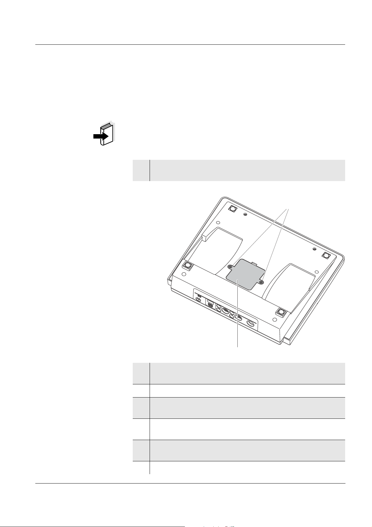
ProLab 1000 Maintenance, cleaning, disposal
1
2
5 Maintenance, cleaning, disposal
5.1 Maintenance
The only maintenance activity required is replacing the batteries.
Note
For maintenance of the electrodes refer to the relevant operating
manuals.
Replacing the batteries
1 Using a screw driver, unscrew the screws (2) of the lid of the
battery compartment.
ba75576e05 11/2013
2 Open the battery compartment (1) on the underside of the
meter.
3 Remove the four batteries from the battery compartment.
4 Place four new batteries (type Micro AAA) in the battery
compartment.
5 Close the battery compartment (1).
The date (day) flashes on the display.
6 Using a screw driver, tighten the screws (2) of the lid of the
battery compartment.
7 Set the date and time (see page 25)
77
Page 78
Maintenance, cleaning, disposal ProLab 1000
CAUTION
Make sure that the poles of the batteries are the right way round.
± signs on the batteries must correspond to the ± signs in the
The
battery compartment.
Only use leakproof alkaline manganese batteries.
5.2 Cleaning
Occasionally wipe the outside of the meter with a damp, lint-free cloth.
Disinfect the housing with isopropanol as required.
CAUTION
The housing components are made out of synthetic materials
(polyurethane, ABS, PMMA), metal and glass. Thus, avoid contact
of the synthetic material with acetone and similar detergents that
contain solvents. Remove any splashes immediately.
5.3 Disposal
Note
This instrument contains batteries. Batteries that have been removed
must only be disposed of at the recycling facility set up for this purpose
or via the retail outlet.
It is illegal to dispose of the instrument in household refuse.
78
ba75576e05 11/2013
Page 79

ProLab 1000 What to do if...
6 What to do if...
6.1 pH and ORP measurement
Error message
Err1
Error message
Err2
Cause Remedy
pH electrode:
– Measured value outside the
measuring range
– Air bubble in front of the
junction
– Air in the junction – Extract air or moisten
– Cable broken – Replace electrode
– Gel electrolyte dried out – Replace electrode
Cause Remedy
– No electrode connected – Connect electrode
– Setting time during calibration
too long
– Use a suitable electrode
– Remove air bubble
junction
– Adjust temperature if
necessary
– Recalibrate
Error message
Error message
CalError
ba75576e05 11/2013
Err4
Cause Remedy
– Temperature not stable during
calibration.
Cause Remedy
pH electrode:
– The values determined for zero
point and slope of the electrode
are outside the allowed limits.
– Junction contaminated – Clean junction
– Electrode broken – Replace electrode
– Adjust temperature if
necessary
– Recalibrate
– Recalibrate
79
Page 80

What to do if... ProLab 1000
Cause Remedy
Buffer solutions:
– Incorrect buffer solutions –
– Change buffer solutions
– Buffer solutions too old – Use only once.
Note the shelf life
– Buffer solutions depleted – Change buffer solutions
No stable measured
Cause Remedy
value
pH electrode:
– Junction contaminated – Clean junction
– Membrane contaminated – Clean membrane
Obviously incorrect
measured values
Test sample:
– pH value not stable – Measure with air excluded if
necessary
– Temperature not stable – Adjust temperature if
necessary
Electrode + test sample:
– Conductivity too low – Use a suitable electrode
– Temperature too high – Use a suitable electrode
– Organic liquids – Use a suitable electrode
Cause Remedy
pH electrode:
– Not connected – Connect electrode
– Cable broken – Replace electrode
– pH electrode unsuitable – Use a suitable electrode
80
– Temperature difference
between buffer and test
sample too high
– Adjust temperature of buffer
or sample solutions
ba75576e05 11/2013
Page 81

ProLab 1000 What to do if...
Cause Remedy
CalClock flashes
Error message Err1
Obviously incorrect
measured values
– Measurement procedure not
– Follow special procedure
suitable
Cause Remedy
– Calibration interval expired – Recalibrate the measuring
system
6.2 ISE measurement
Cause Remedy
– Measuring range exceeded – Dilute test sample
Cause Remedy
– Electrode not connected – Connect electrode
Error message, Error
(invalid
calibration)
– Cable broken – Replace electrode
Cause Remedy
ISE electrode:
– Moisture in the plug – Dry plug
– Electrode obsolete – Replace electrode
– Electrode unsuitable for the
– Use suitable electrode
range to be measured
– Socket damp – Dry socket
Calibration procedure:
– Wrong sequence of standards
– Select correct sequence
for three point calibration
– Calibration standards do not
have the correct temperature
(max.
± 2 °C temperature
– Adjust the temperature of
the calibration standards
difference)
ba75576e05 11/2013
81
Page 82

What to do if... ProLab 1000
Warning [TempErr]
Cause Remedy
Warning [ISEErr]
Meter does not react
to keystroke
– Temperature difference
between measurement and
– Adjust the temperature of
the test sample
calibration greater than 2 K.
Cause Remedy
– Electrode voltage outside
– Recalibrate
calibrated range
6.3 General errors
Cause Remedy
– Operating condition undefined
or EMC load unallowed
– Processor reset:
Press the <On/Off> and
<SC> key simultaneously.
Time is lost
Cause Remedy
– Buffer batteries empty – Exchange buffer batteries
(see page 77)
82
ba75576e05 11/2013
Page 83

ProLab 1000 Technical data
Stand March 3, 2010Translation of the legally binding German version
7 Technical data
7.1 General data
Dimensions approx. 240 x 280 x 70 mm
Weight approx. 2.5 kg (without power pack)
Mechanical structure Type of protection IP 54
Electrical safety Protective class III
Test certificates cETLus, CE
Ambient
conditions
Power
supply
Serial
interface
Storage - 25 °C ... + 65 °C
Operation + 5 °C ... + 45 °C
Climatic class 2
Power pack FRIWO FW7555M/09, 15.1432.500-00
Friwo Part. No. 1883259
Input: 100 ... 240 V ~ / 50 ... 60 Hz / 400 mA
Output: 9 V = / 1.5 A
Connection max. overvoltage category II
Primary plugs contained in the scope of
delivery: Euro, US, UK and Australian.
Batteries
(to buffer the system
clock in the case of a
power failure)
Connection of the PC cable (Z390) or printer cable (Z393)
Baud rate adjustable:
Type RS232, data output
Data bits 8
4 x 1.5 V alkali-manganese batteries, Type
AAA
1200, 2400, 4800, 9600, 19200 Baud
USB interface Automatic switch-over when a USB cable is connected.
Guidelines
and norms used
ba75576e05 11/2013
Stop bits 2
Parity None
Handshake RTS/CTS
Cable length Max. 15m
Type USB 1.1 (device)
Cable length max. 3 m
EMC EC guideline 2004/108/EC
EN 61326-1 Class B
FCC Class A
83
Page 84

Technical data ProLab 1000
Stand March 3, 2010Translation of the legally binding German version
Instrument safety EC guideline 2006/95/EC
EN 61010-1
ANSI/UL 61010-1
CAN/CSA-C22.2 No. 61010-1
Measuring ranges,
resolution
Radio data
transmission
EC guideline 1999/5/EC
EN 300 330-2
EN 50364
EN 60950-1
Climatic class VDI/VDE 3540
IP protection class EN 60529
7.2 Measuring ranges, resolution, accuracy
7.2.1 pH/ORP
Variable Measuring range Resolution
pH - 2.000 ... + 20.000
- 2.00 ... + 20.00
U [mV] - 1999.9 ... + 1999.9
- 1999 ... + 1999
T [°C] - 10.0 ... + 120.0 0.1
0.001
0.01
0.1
1
Manual
temperature input
Variable Range Increment
T
[°C] - 10 ... + 130 1
manual
Accuracy (± 1 digit) Variable Accuracy Temperature of the test
sample
pH ± 0.003
+ 15 °C ... + 35 °C
± 0.01
U [mV] / range
- 999.9 ... + 999.9 ± 0.2 + 15 °C ... + 35 °C
- 1999 ... + 1999 ± 1 + 15 °C ... + 35 °C
T [°C] / temperature sensor
± 0.1 0 °C ... + 55 °C
Note
The measuring ranges and accuracy values specified here apply
exclusively to the meter. The accuracy of the sensors has also to be
taken into account.
84
ba75576e05 11/2013
Page 85

ProLab 1000 Technical data
Stand March 3, 2010Translation of the legally binding German version
7.2.2 ISE
Measuring ranges,
resolution
Variable Measuring range Resolution
ISE [mg/l] 0.000 ... 10.000
10.00 ... 100.00
100.0 ... 1000.0
1000 ... 999999
ISE [µmol/l] 0.000 ... 9.999
10.00 ... 99.99
100.0 ... 999.9
1000 ... 999999
[mmol/l] 10.00 ... 99.99
100.0 ... 999.9
1000 ... 999999
ISE [mg/kg] 0.000 ... 9.999
10.00 ... 99.99
100.0 ... 999.9
1000 ... 999999
ISE [ppm] 0.000 ... 9.999
10.00 ... 99.99
100.0 ... 999.9
1000 ... 999999
ISE [%] 0.000 ... 9.999
10.00 ... 99.99
100.0 ... 999.9
1000 ... 999999
0.001
0.01
0.1
1
0.001
0.01
0.1
1
0.01
0.1
1
0.001
0.01
0.1
1
0.001
0.01
0.1
1
0.001
0.01
0.1
1
Manual
temperature input
ba75576e05 11/2013
Variable Range Increment
T
[°C] - 20 ... + 130 1
manual
Note
The measuring ranges and accuracy values specified here apply
exclusively to the meter. The accuracy of the sensors has also to be
taken into account.
Note
The measuring ranges and accuracy values specified here apply
exclusively to the meter. The accuracy of the sensors has also to be
taken into account.
Note
The measuring ranges and accuracy values specified here apply
exclusively to the meter. The accuracy of the sensors has also to be
taken into account.
85
Page 86

Technical data ProLab 1000
FCC Class A Equipment Statement
Note: This equipment has been tested and found to comply with the
limits for a Class A digital device, pursuant to Part 15 of the FCC
Rules. These limits are designed to provide reasonable protection
against harmful interference when the equipment is operated in a
commercial environment. This equipment generates, uses, and can
radiate radio frequency energy and, if not installed and used in
accordance with the instruction manual, may cause harmful
interference to radio communications. Operation of this equipment in
a residential area is likely to cause harmful interference in which
case the user will be required to correct the interference at his own
expense.
Any changes or modifications not expressly approved by the party
responsible for compliance could void the user's authority to operate
the equipment.
Stand March 3, 2010Translation of the legally binding German version
86
ba75576e05 11/2013
Page 87

ProLab 1000 Lists
8Lists
This chapter provides additional information and orientation aids.
Abbreviations The list of abbreviations explains the indicators and abbreviations that
appear on the display and in the manual.
Specialist terms The glossary briefly explains the meaning of the specialist terms.
However, terms that should already be familiar to the target group are
not described here.
Trademarks used The list comprises the trademarks used in the present document and
their owners.
Index The index will help you to find the topics that you are looking for.
ba75576e05 11/2013
87
Page 88

Lists ProLab 1000
Abbreviations
°C Temperature unit, degrees Celsius
°F Temperature unit, degrees Fahrenheit
Cal Automatic calibration using a selected buffer set
dDay
h Hour
j Year
LoBat Batteries almost empty (Low battery)
m Month
mV Voltage unit
mV/pH Unit of the electrode slope (internat. mV)
pH pH value
S Slope (internat. k)
SELV Safety Extra Low Voltage
U Voltage
88
ba75576e05 11/2013
Page 89

ProLab 1000 Lists
Glossary
Adjusting To manipulate a measuring system so that the relevant value (e. g. the
displayed value) differs as little as possible from the correct value or
a value that is regarded as correct, or that the difference remains
within the tolerance.
AutoRange Name of the automatic selection of the measuring range.
Calibration Comparing the value from a measuring system (e. g. the displayed
value) to the correct value or a value that is regarded as correct.
Often, this expression is also used when the measuring system is
adjusted at the same time (see adjusting).
Electrode zero point The zero point of a pH electrode is the pH value at which the
electromotive force of the pH electrode at a specified temperature is
zero. Normally, this is at 25 °C.
Electromotive force of
an electrode
The electromotive force (voltage) U of the electrode is the measurable
electromotive force of an electrode in a solution. It equals the sum of
all the galvanic voltages of the electrode. Its dependency on the pH
results in the electrode function, which is characterized by the
parameters, slope and zero point.
Junction The junction is a porous body in the housing wall of reference
electrodes or electrolyte bridges. It forms the electrical contact
between two solutions and makes electrolyte exchange more difficult.
The expression, junction, is also used for ground or junction-less
transitions.
Measured parameter The measured parameter is the physical dimension determined by
measuring, e. g. pH, conductivity or D.O. concentration.
Measured value The measured value is the special value of a measured parameter to
be determined. It is given as a combination of the numerical value and
unit (e. g. 3 m; 0.5 s; 5.2 A; 373.15 K).
Molality Molality is the quantity (in Mol) of a dissolved substance in 1000 g
solvent.
Offset potential The measurable potential of a symmetrical electrode, the membrane
of which is immersed in a solution with the pH of the nominal electrode
zero point. The asymmetry is part of the offset potential.
ORP voltage The ORP is caused by oxidizing or reducing substances dissolved in
pH value The pH is a measure of the acidic or basic effect of an aqueous
ba75576e05 11/2013
water if these substances become effective on an electrode surface
(e. g. a gold or platinum surface).
solution. It corresponds to the negative decadic logarithm of the molal
hydrogen ions activity divided by the unit of the molality. The practical
pH value is the value of a pH measurement.
89
Page 90

Lists ProLab 1000
Potentiometry Name of a measuring technique. The signal (depending on the
measured parameter) of the electrode is the electrical potential. The
electrical current remains constant.
Reset Restoring the original condition of all settings of a measuring system.
Resolution Smallest difference between two measured values that can be
displayed by a meter.
Slope The slope of a linear calibration function.
Stability control Name for a function to check the stability of the measured value.
Standard solution The standard solution is a solution where the measured value is
known by definition. It is used to calibrate a measuring system.
Test sample Designation of the test sample ready to be measured. Normally, a test
sample is made by processing the original sample. The test sample
and original sample are identical if the test sample was not processed.
Zero point Designation for the offset potential of a pH electrode. It is the
measurable potential of a symmetrical electrode, the membrane of
which is immersed in a solution with the pH of the nominal electrode
zero point (pH = 7).
90
ba75576e05 11/2013
Page 91

ProLab 1000 Lists
Trademarks used
Trademark Owner of the trademark
Baker Mallinckrodt Baker, Inc.
Beckman Beckman Instruments, Inc.
Fisher Fisher Scientific Company
Fluka Fluka AG
Hamilton Hamilton Company Corporation
Merck Merck KGaA
Metrohm Metrohm AG
Mettler Toledo Mettler Toledo
Precisa Precisa Instruments AG
Radiometer Radiometer
Windows Microsoft Corporation
ba75576e05 11/2013
91
Page 92

Lists ProLab 1000
92
ba75576e05 11/2013
Page 93

ProLab 1000 Index
Index
A
Authorized use .........................................15
B
Battery compartment ................................77
C
Calibration
...................................................55
ISE
pH .....................................................40
Calibration evaluation
...................................................57
ISE
pH .....................................................45
calibration history .....................................70
Calibration interval ...................................46
Calibration points
...................................................55
ISE
pH .....................................................44
calibration records ....................................68
Cleaning .................................................78
Connecting sensors .................................10
M
Measured value display ........................... 21
Measured value memory
................................................... 65
Edit
Measurement accuracy ............................ 46
Measurement data storage
Delete
Storage locations ............................... 61
Measurement dataset .............................. 61
Measurement window ................................ 9
Measuring
ORP voltage ...................................... 36
pH .................................................... 34
Measuring menu
pH/ORP ............................................ 38
Memory administration ............................. 64
Menus (navigation) .................................. 21
Messages ............................................... 22
MultiLab pilot .......................................... 74
............................................... 65
.................................................. 53
ISE
.................................................. 54
ISE
D
Data filter ................................................67
Dataset ...................................................61
Date and time ..........................................25
Default settings
Measured parameter
System settings ..................................75
Display illumination ....................................9
...........................74
F
Filter .......................................................67
Firmware update ......................................95
I
Initial commissioning ................................18
Initialize ...................................................74
ISE standard solutions ..............................55
K
Key functions .............................................8
Keys .........................................................8
O
Obligations of the purchaser ..................... 16
Operational safety ................................... 16
P
pH buffer sets ......................................... 40
Precautions ............................................ 15
Print ....................................................... 73
R
Reset ..................................................... 74
RS232 interface ...................................... 72
S
Safe operation ........................................ 16
Safety ..................................................... 15
Sample display .......................................... 9
Saving .................................................... 61
at intervals ......................................... 63
automatic .......................................... 63
manual .............................................. 62
Scope of delivery ..................................... 17
ba75576e05 11/2013
93
Page 94

Index ProLab 1000
Single-point calibration
pH
.................................................... 48
Slope
.................................................. 55
ISE
pH .................................................... 40
Socket field ............................................. 10
Stability control
automatic
manual
ISE
ORP ............................................ 36
pH ............................................... 34
Status line ................................................ 9
Storage interval ....................................... 63
System menu .......................................... 30
General information ........................... 31
Sample display .................................. 30
.......................................... 32
.............................................. 53
T
Temperature measurement
.................................................. 52
ISE
pH .................................................... 33
Three-point calibration
................................................... 60
ISE
pH .................................................... 49
Transmitting data .................................... 71
Transmitting measured values .................. 71
Two-point calibration
ISE
.................................................. 59
pH .................................................... 48
Z
Zero point of the pH electrode .................. 40
94
ba75576e05 11/2013
Page 95
ProLab 1000
Appendix
A.1 Firmware update
General information With the Update_ProLab1000_2000 program and a PC you can update
the firmware of the ProLab 1000 to the newest version.
Available firmware updates can be found on the Internet.
Connect the meter to a PC for the update.
For the update via the USB interface, the following is required:
a free USB interface (virtual COM port) on your PC
the driver for the USB interface (installation of the USB driver from
the installation CD-ROM, see page 71)
the USB cable (included in the scope of delivery of the
ProLab 1000).
For the update via the RS232 interface, the following is required:
Program installation
Program start
Firmware update
a free RS232 interface on your PC
the RS232 cable, Z390.
1 With the installation program,
"Install_Update_ProLab1000_2000_Vx_yy_English.exe",
install the firmware update program on a PC.
2 Start the "Update_ProLab1000_2000" program from the
Windows start menu.
3 If necessary, change the language in the language menu.
4 Connect the ProLab 1000 to a USB interface (virtual COM port)
of the PC with the aid of the USB interface cable.
or
Connect the ProLab 1000 to a serial interface (COM port) of
the PC with the aid of the Z390 interface cable.
5 Switch on the ProLab 1000.
ba75576e05 11/2013
6 Start the updating procedure with OK in the firmware update
program.
7 Follow the instructions of the firmware update program.
During the programming process, a corresponding message
and a progress bar (in %) is displayed.
The programming process takes approx. two minutes. A
terminatory message is displayed after a successful
programming process. The firmware update is completed.
95
Page 96

ProLab 1000
8 Disconnect the ProLab 1000 from the PC.
The ProLab 1000 is ready for operation.
After switching the meter off and on you can check whether the meter
has taken over the new software version.
96
ba75576e05 11/2013
Page 97

ProLab 1000
A.2 Menus
A.2.1 Data storage
Storage & config (<MENU/OK
– Data storage
– Manual data storage (<RCL>)
– Display
– Output to RS232/USB
– Data filter
– Filter
– No filter
– Date & SAMPLE ID
– SAMPLE ID
– Date
– From : TT.MM.JJ
– Until : TT.MM.JJ
– SAMPLE ID : 0 ... 999
– Erase
– Automatic data storage (<RCL
– Display
– Output to RS232/USB
– Data filter
– Erase
_>)
_>)
ba75576e05 11/2013
– Calibration data storage (<CAL
– Display
– Output to RS232/USB
– Calibration history
–pH
–ISE
– Display (see page 98)
– System (see page 98)
_>)
97
Page 98

A.2.2 Display
ProLab 1000
Storage & config (<MENU/OK
– Data storage (see page 97)
– Display
– Time : On /Off
– Date : On /Off
– System (see page 98)
A.2.3 System
Storage & config (<MENU/OK
– Data storage (see page 97)
– Display (see page 98)
– System
– General
– Language
– Deutsch
– English
–(etc.)
– Beep : On /Off
– Illumination : On /Off
– Contrast : 0 ... 100 %
_>)
_>)
– Measurement
– Temperature unit : ° C /° F
– Stability control : Auto / Off
– Interface
– Baud rate : 1200, 2400, 4800, 9600, 19200
– Output format : ASCII / CSV
– Output header
– Clock function
– Time
– Date
– Date format
– Service information
– Reset
98
ba75576e05 11/2013
Page 99

ProLab 1000
A.2.4 <STO_>
_> (<STO_>)
<STO
– SAMPLE ID
– Interval : 1, 5 s, 10 s, 30 s,
– Duration : 1 min ... x min
: 1 ... 999
1 min, 5 min, 10 min, 15 min, 30 min, 60 min
A.2.5 <PRT
<PRT
_> (<PRT_>)
– Interval : 1, 5 s, 10 s, 30 s,
_>
1 min, 5 min, 10 min, 15 min, 30 min, 60 min
ba75576e05 11/2013
99
Page 100

A.2.6 pH/U
pH/U (<MENU/OK>)
– Calibration
– Calibration record
– Calibration history
– Buffer
– NIST/DIN
– TEC
–Merck 1
–Merck 2
–Merck 3
–Merck 4
–Merck 5
– DIN 19267
– Mettler US
– Mettler EU
– Fisher 1
–Fluka BS
– Radiometer
–Baker
– Metrohm
–Beckman
–Hamilton DC
–Precisa
– Reagecon TEC
– Reagecon 20
– Reagecon 25
– Riedel-de Haen
ProLab 1000
100
– Calibration interval : 1 ... 999 d
– Unit for zero point : mV / pH
– Unit for slope : mV/pH / %
– Man. temperature : -20 ... +130 °C
– Reset
– High resolution pH : On /Off
– High resolution mV : On /Off
ba75576e05 11/2013
 Loading...