

Page 1

Operating Manual
System OxiTop® Control
OxiTop® OC100
Controller
OxiTop®-C
Measuring Heads
OC Model
Page 2

2 BA31114e5 07/2006 BA31114e5 07/2006 3
Page 3

Safety Instructions
This instrument is built and checked according to IEC 1010, safety rules for
electronic measuring instruments and left the factory secure from a safety
engineering aspect.
The smooth functioning and operational safety of the equipment can only be
guaranteed by following the general safety precautions applicable and the special
safety instructions given in this operating manual.
– The trouble-free function and operational safety of the instrument can only be
guaranteed by following the climate conditions specified in the chapter
"Technical data" in this operating manual.
– If the system is transported from a cold environment to a warm environment, its
function can be impaired as a result of condensation forming. In this case, the
temperature of the equipment must be allowed to adapt to room temperature
before putting it into operation again.
– Adjustment of the equipment and maintenance or repair work must only be
performed by personnel authorized by WTW.
– If safe operation is no longer possible, the equipment must be taken out of
service and secured against inadvertent operation by labeling with warning
signs.
– The safety of the user can be affected by the instrument if, for example,
• the instrument is visibly damaged,
• the instrument no longer operates as prescribed,
• the instrument has been stored under adverse conditions for a lengthy
period of time,
• the instrument was exposed to adverse transport conditions.
– Basically, if you are in any doubt, please return the instrument for repair or
maintenance to the manufacturer of the equipment,
"Wissenschaftlich-Technische-Werkstätten GmbH".
Please read these safety instructions carefully before installing
the instrument!
Page 4

Contents
Safety Instructions .................................................................................................... 3
Contents.....................................................................................................................4
Introduction ...............................................................................................................6
The measuring principle ........................................................................................7
The OxiTop
Operating modes ...................................................................................................8
Litterature.........................................................................................................8
Operating Elements ..................................................................................................9
Controller keybord .................................................................................................9
General Operating Principles.................................................................................10
Switching On ...........................................................................................................11
Switching on the controller...................................................................................11
Switching on the measuring heads .....................................................................11
Operating Mode: Routine BOD...............................................................................12
Sample preparation .............................................................................................12
Start the measurement ........................................................................................12
Call up all data ....................................................................................................15
Sample management...........................................................................................17
Show sample ......................................................................................................19
Erase data of finished samples ...........................................................................20
Show measuring head list....................................................................................21
Call up data .........................................................................................................22
Call up data - Stop ...............................................................................................24
Evaluation............................................................................................................25
Curve display of samples that are too cold ....................................................26
Measured values outside the measurement ranges ......................................26
Printing.................................................................................................................27
Operating Mode: Standard BOD ............................................................................29
Sample preparation .............................................................................................29
Start the measurement ........................................................................................29
Call up all data ....................................................................................................32
Sample management...........................................................................................35
Show sample ......................................................................................................36
Erase data of finished samples ...........................................................................37
Show measuring head list....................................................................................38
Call up data .........................................................................................................39
Call up data - Stop ...............................................................................................42
Evaluation............................................................................................................44
Sample statistics..................................................................................................45
Excluding a curve ................................................................................................46
Cursor interrogation .............................................................................................48
Curves display for cold samples ....................................................................49
Measured values outside the measuring range .............................................50
Print .....................................................................................................................51
4 BA31114e5 07/2006 BA31114e5 07/2006 5
®
Control measuring system ...............................................................7
Page 5

Contents
GLP/Tools ................................................................................................................53
GLP/Tools main menu .........................................................................................53
Show free measuring heads ................................................................................54
Show settings ......................................................................................................55
Settings................................................................................................................56
Operating mode .............................................................................................56
Measuring time...............................................................................................57
Date/Time.......................................................................................................57
GLP ................................................................................................................58
GLP - calibrating interval (”Calinterval”) ...................................................59
Memory ..........................................................................................................60
AutoTemp.......................................................................................................61
Switch-off interval...........................................................................................63
Language .......................................................................................................64
Check...................................................................................................................65
Show measuring heads..................................................................................65
Measuring head info.......................................................................................66
Controller info.................................................................................................67
Cal test ...........................................................................................................68
Pneumatic test measuring head.....................................................................71
Maintenance ........................................................................................................72
Erase finished samples..................................................................................72
Reset/release measuring head ......................................................................74
RS232 Interface .......................................................................................................76
Cleaning ...................................................................................................................77
Cleaning the sample bottles ................................................................................77
Cleaning the controller and measuring heads .....................................................77
Power Supply...........................................................................................................78
OxiTop®-OC100 controller ...................................................................................78
®
OxiTop
Disposing of the batteries ....................................................................................83
What to do if ...? ......................................................................................................84
Display messages................................................................................................84
Requirements / Problems ....................................................................................90
Accessories and Spare Parts.................................................................................95
Technical Data .........................................................................................................96
Note:
This operating manual refers to software release 1.xx.
The right to implement minor changes is reserved.
-C measuring head.................................................................................82
Page 6

Introduction
The OxiTop® Control system provides a further development of the mercury-free,
measured value storing OxiTop
a multitude of new technological features that simplify the whole process of the BOD
determination for the user. Furthermore, the instrument is almost unlimited with
respect to its sample capacity and use. It can also be expanded flexibly to fulfill its
tasks. In addition to its application in the water economy, the OxiTop
”respirometric” measuring principle can also be used in other areas such as
• Evaluation of biological degradability, i.e. testing aerobic degradation
(e.g. test according to OECD 301F)
• Evaluation of respiration and toxicity in earth, sludge, waste and sediment (e.g.
extraction of earth contaminated according to recovery concepts)
• Evaluation of the respiration rate of cell cultures
• Microbiological growth and stress examinations
®
BOD measurement system. The instrument provides
®
Control with its
6 BA31114e5 07/2006 BA31114e5 07/2006 7
Page 7

Introduction
In addition, in conjunction with the enhanced OxiTop
accessories, the OxiTop
®
-C measuring heads can also be used to
®
Controller OC110 and relevant
• Measure anaerobic degradation processes (e.g. biogas evaluation)
The measuring principle
The sample bottles are filled according to the data visible in the display (BOD
measuring range with assigned water sample amount). The microorganisms draw
oxygen to degrade organic substances from the amount of air remaining in the closed
system. The carbon dioxide formed by this process is absorbed. Due to the reduction
in the amount of oxygen, the pressure in the bottle sinks. This change is detected and
stored by the measuring head. After the data transfer to the controller, it is used to
determine the BOD value.
Further information is given in the WTW BOD handbook.
The OxiTop® Control measuring system
The 6 or 12 position OxiTop
and consist of the OC100 OxiTop
inductive stirring system and various accessories.
The measured value determination and storage of the measurement data is
performed in the measuring head. This data is transmitted via ”infrared to the
controller” without the need for wires and then calculated to the BOD value. The user
can start his individual measuring program and printout the calculated data via the
TD100 IR printer or further process it via a PC program using the ”Routine BOD” and
”Standard BOD” operating modes described in detail in this operating manual. The
user interface appears in one of 5 selectable languages. An overview of the entire
sample management together with the status and function response is shown on the
display. With the aid of the display function, sample identification is no longer
required. Via the OxiTop
to 144 measuring positions.
An overview of the essential advantages
• DIN procedure • Modular extensions
• Mercury-free • Data storage
• Precise • Comfortable handling
• Automatic sample management
• Automatic measurement report
®
Control systems are configured for BOD determination
®
controller, the OxiTop®-C measuring heads, the
®
-C IS 6/12 expansion sets, the system can be extended up
• Wireless data transfer,
(even through glass or transparent
plastic)
Page 8

General Operating Principles
Operating modes
The OC100 controller has 2 standard operating modes that differ from one another as
described below:
”Routine BOD”
This mode provides the user-friendly ”quick introduction”. The samples are managed
as single samples. The setting functions are logically restricted.
”Standard BOD”
The main difference to the ”Routine BOD” mode is in the parallel sample process for
up to 12 measuring heads per whole sample with mean value formation and statistical
evaluation. The setting is made via the function ”GLP/Tools”. The extended setting
functions allow a multitude of further options (see chapter ”GLP/Tools”). The samples
plotted in the ”Standard BOD” mode are not displayed in the ”Routine BOD” mode.
A table of the settings in the delivery state is given in the chapter ”GLP/Tools”.
Literature
Further information on this subject can be obtained at no cost from WTW:
- BOD handbook
- Application reports
- Special printouts
8 BA31114e5 07/2006 BA31114e5 07/2006 9
Page 9
Switching On
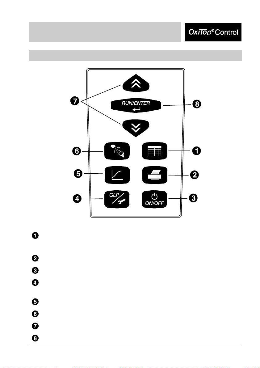
Controller keyboard
Sample management: List of samples, reading the data of individual
measuring heads or samples, displays of measuring
heads or samples
Printing of measurement data and settings
Switching on/off
GLP / Tools: Display free measuring heads, display or change settings,
perform checks or maintenance
Evaluation: Graphic and numerical display of measuring data
Communication with measuring heads: Start measuring, call up data
Select
Confirmation of entries
Page 10
General Operating Principles
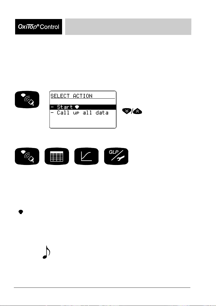
Representation of keys and displays:
Example: Pressing the ”Communication” button causes the mode to change to the
”Communication with the measuring heads” mode of operation:
Required
action: press
button.
The instrument displays:
Description of what the action
caused and possible further
request:
Starting communication with the
measuring heads.
Select a menu item using
.
Function keys:
These function keys are used to start or change a function.
Confirmed data and settings are preserved.
Display:
- In selection menus, the selected function or line appear in a lighter font on a
dark background
- :
Measuring head:
Each measuring head that receives a command from the controller, indicates this by
a short flashing signal.
Signal tone: This symbol means: A signal tone sounds.
Notes:
Instructions and additional information appear in italics.
Symbol for an OxiTop®-C measuring head
10 BA31114e5 07/2006 BA31114e5 07/2006 11
Page 11
Switching On
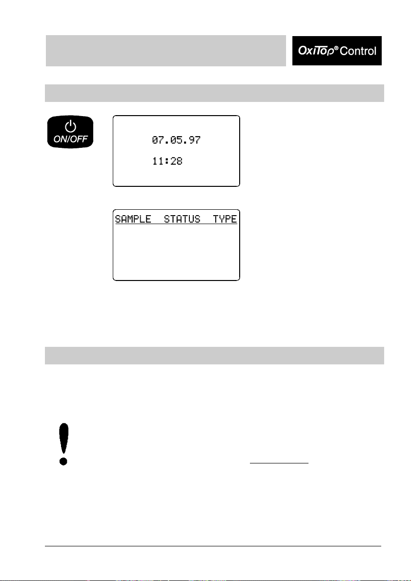
Switching on the controller
The current date and time appear
(important for the allocation of
sample numbers).
If the date/time is incorrect,
undertake corrections in
”GLP/Tools”.
The instrument is in the sample
management
(Routine mode,
in the delivery state).
Switching on the measuring heads
The measuring heads are immediately ready for operation. The controller switches
the measuring heads independently on and off during communication.
To avoid malfunctions:
In case of using two or more controllers please pay attention to the following:
Absolutely avoid starting measuring heads simultaneously
between controllers is less than 3 meters when doing this.
if the distance
Page 12
Operating Mode: Routine BOD
Operating mode: Routine BOD
Sample preparation
See WTW application reports
(contained within the scope of delivery of the accessories supplied).
Screw the OxiTop
and tightly close them.
Important note:
Never use joint grease or other lubricant for your OxiTop
heads. Some of these products contain solvents that can cause severe damage
to the plastic housing.
The sealing of the BOD bottles is also perfectly adequate without grease.
However, you should always wipe off heavy contamination and particles on the
sealing surfaces of the rubber sleeves and OxiTop
liability for damage due to the use of joint grease.
Start the measurement
-C measuring heads onto the sample bottles
-C. WTW accepts no
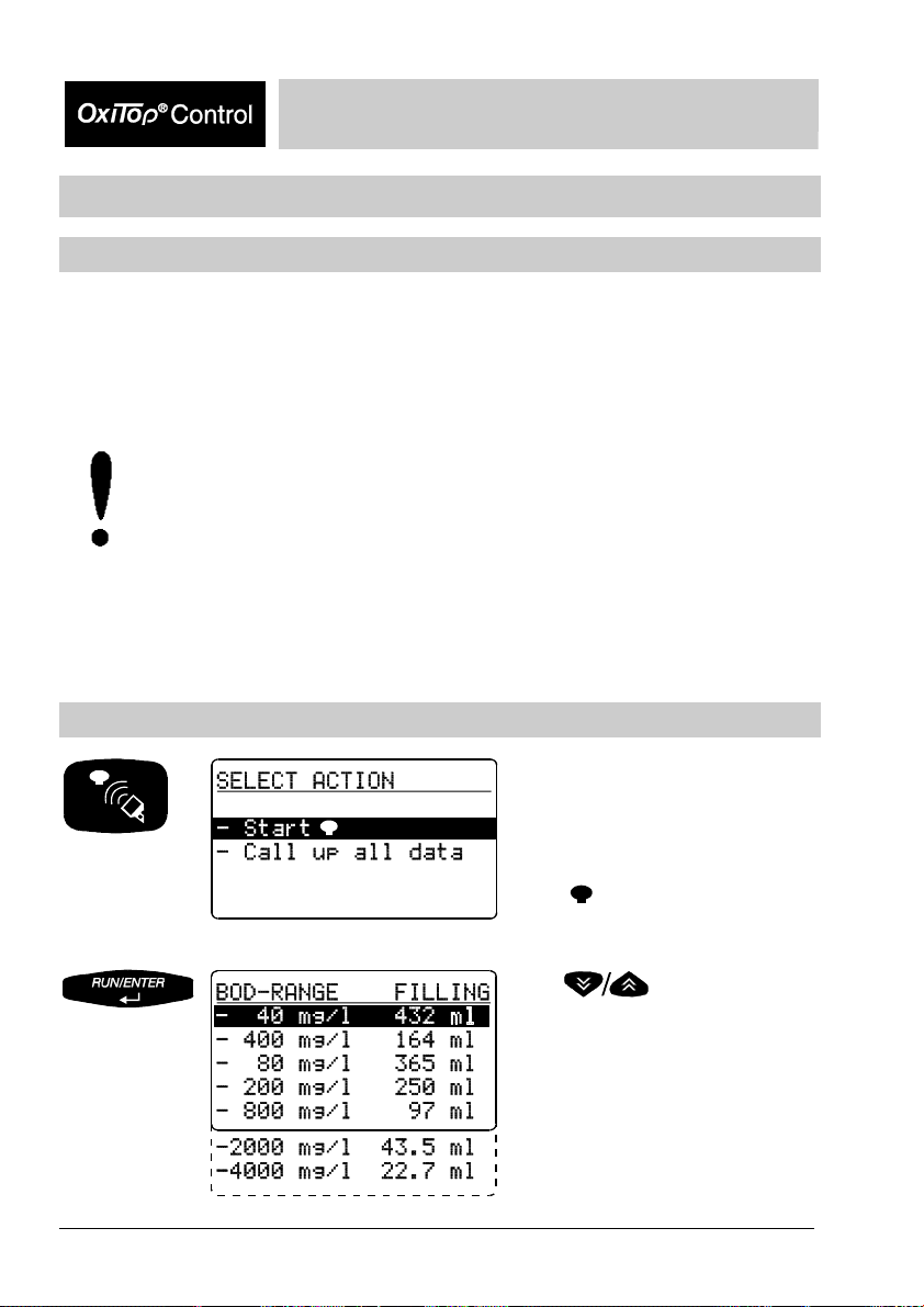
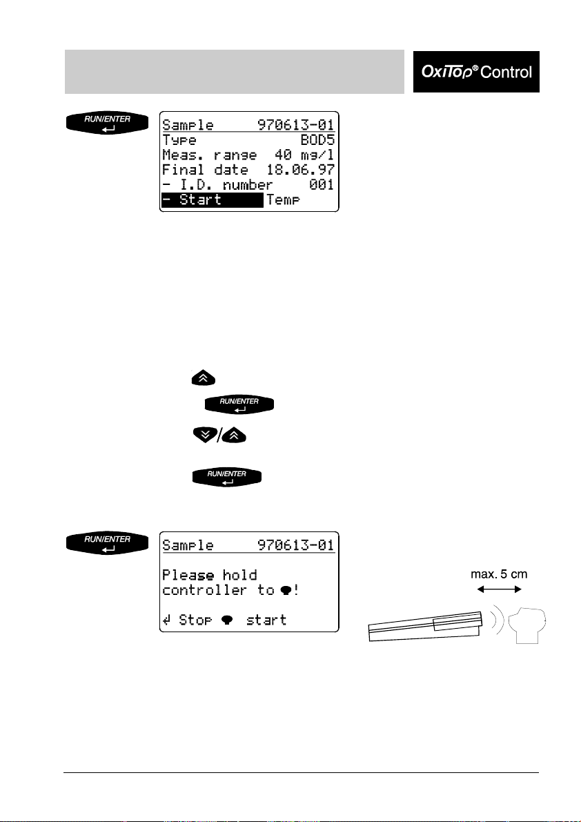
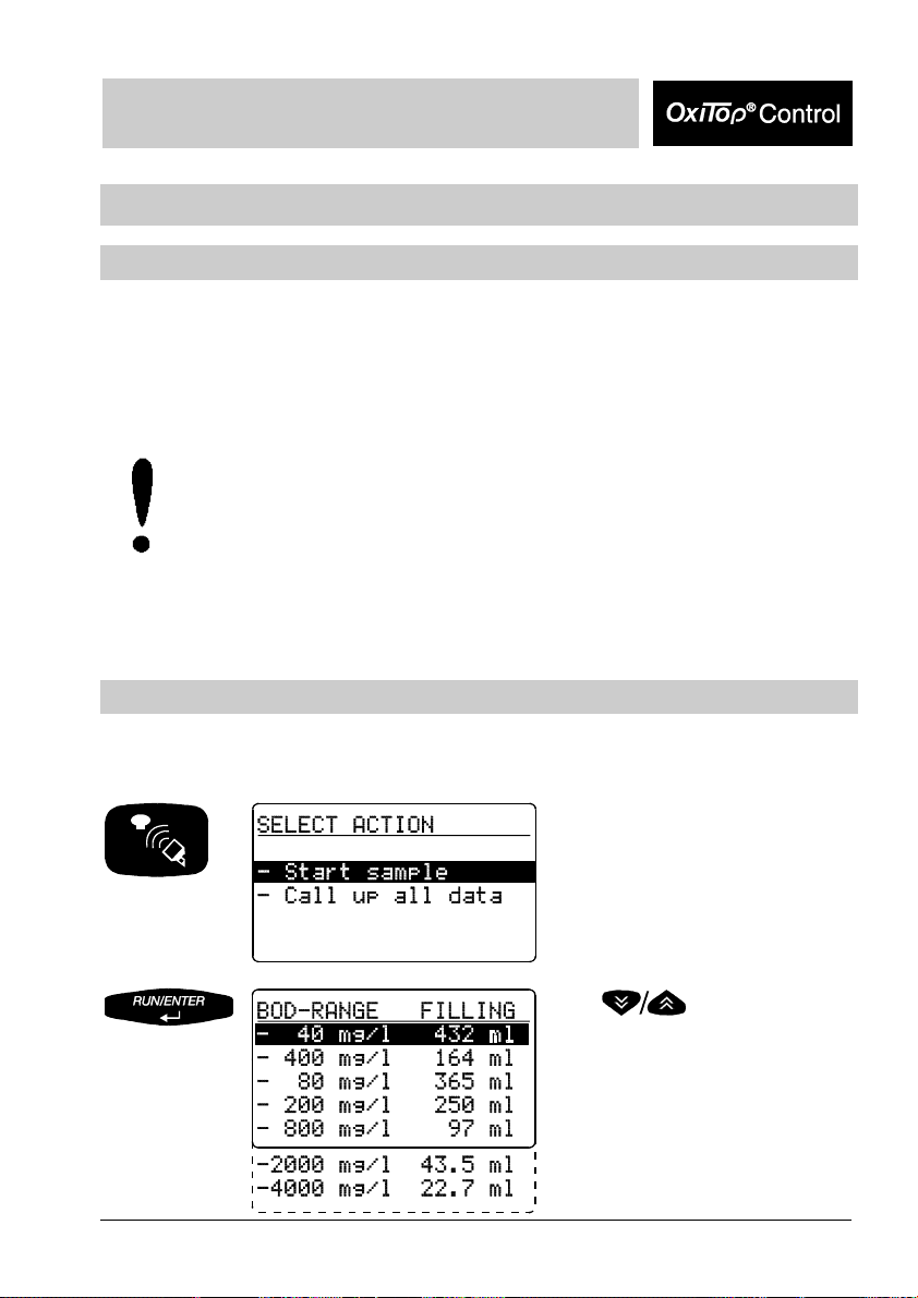
Entry into the mode
“Communication with the
measuring heads“.
Preselected:
Start
Use
to select the measurement range.
The filling volume required is given
in the right-hand column.
The controller stores the setting
(memory function: the last selected
measurement range is set).
(measuring head).
-C measuring
12 BA31114e5 07/2006 BA31114e5 07/2006 13
Page 13
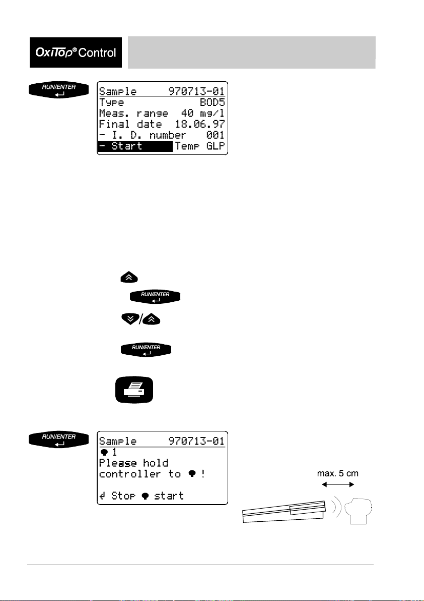
Operating Mode: Routine BOD
Confirm the selected
measurement range for the
sample. The automatically
allocated sample number is given
in the header line (YY/MM/DD and
sequential number).
Additional information:
Type of measurement, run time, measurement range, final date, Id
number.
“Temp“ display => the AutoTemp function (see the chapter “GLP/Tools”)
is set as a default in the routine mode.
Change the Id number of the additional identification of the sample
(e.g. extraction location) as follows:
- Use
- Press and
- Use
(setting range 001 ... 255).
- Use
to move the cursor to the Id number,
to set the Id number required
to confirm this.
Confirm the start of the
measurement. Contact selection:
The controller repeatedly sends the
start information in the scanner
mode until successful feedback is
received from the OxiTop®-C
measuring head.
Page 14
Operating Mode: Routine BOD
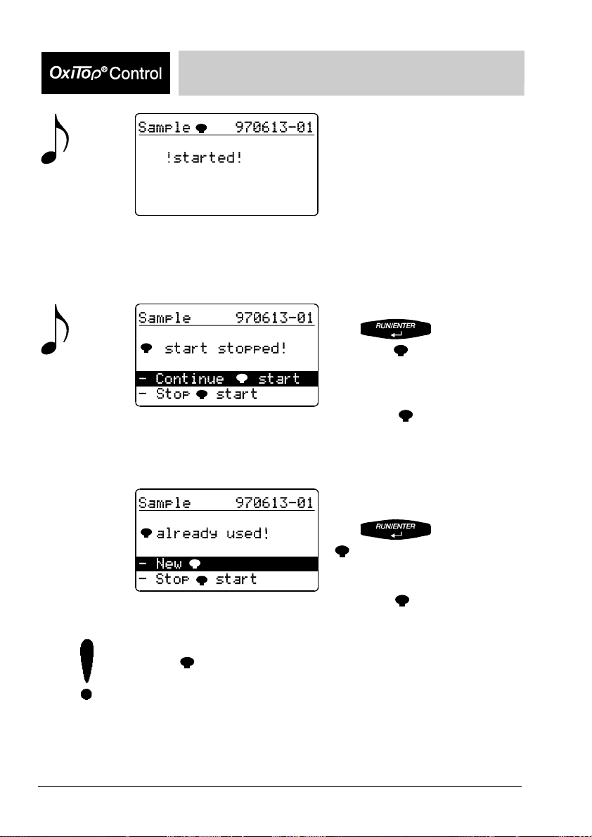
Displays “Started“. From this point in
time, the sample exists within the
If no sample starts (e.g. because the controller was not held to - or not
held close enough to - a measuring head):
sample management. Subsequently,
the controller returns automatically to
the input menu.
The sample start was stopped.
Use
If an attempt is made to start an already started sample:
“Continue
controller to the measuring head
(see above).
Use “Stop start“ if you want to
return to the entry menu.
to confirm
start“ and hold the
In the delivery state, the controller automatically makes space when
“Start
erases the oldest finished sample (if a finished sample is available). You
can change this setting in “manual erase” (see the chapter “GLP/Tools Settings”).
” is selected if the measured value memory is full. To do this, it
Display shows “Measuring head
already used!”
Use
” and hold the controller to the
measuring head (see above).
Use “Stop start“ if you want to
return to the entry menu.
to confirm “New
14 BA31114e5 07/2006 BA31114e5 07/2006 15
Page 15
Operating Mode: Routine BOD
Call up all data
This function is used to call up the data of all measuring heads.
For the call up of the data of individual measuring heads: see the chapter on sample
management.
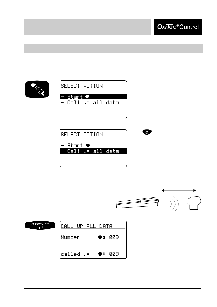
Entry menu “Communication with
the measuring heads“.
Point the controller at the measuring
heads:
Use
to select “Call up all data“.
40 cm to 100 cm
Queries the data of all active
measuring heads in the scanner
mode.
The controller stores the data
obtained and updates the list of
the sample management.
Duration of a pass: approx. 3
seconds for 12 measuring heads
in a stirring system.
Page 16
Operating Mode: Routine BOD
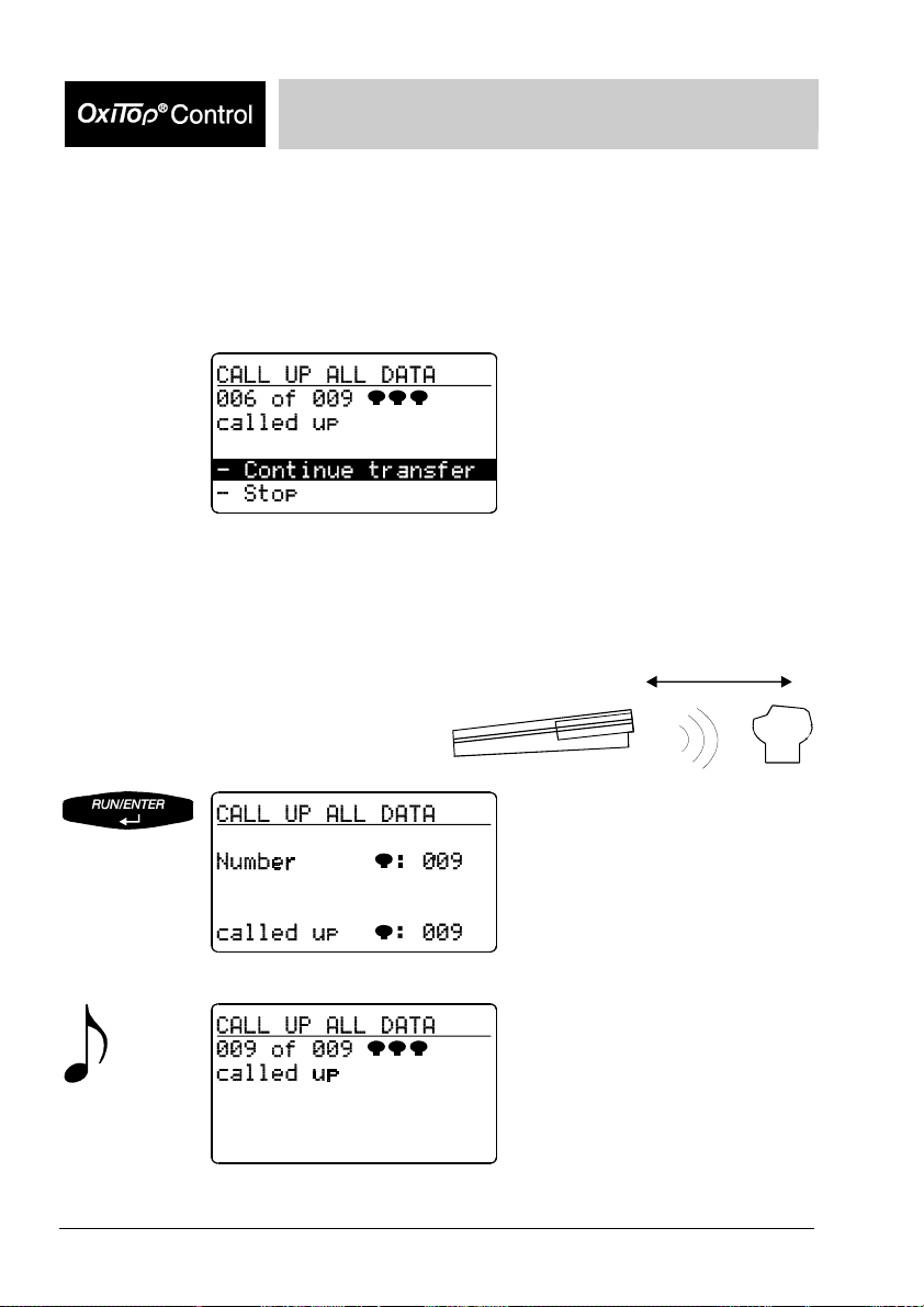
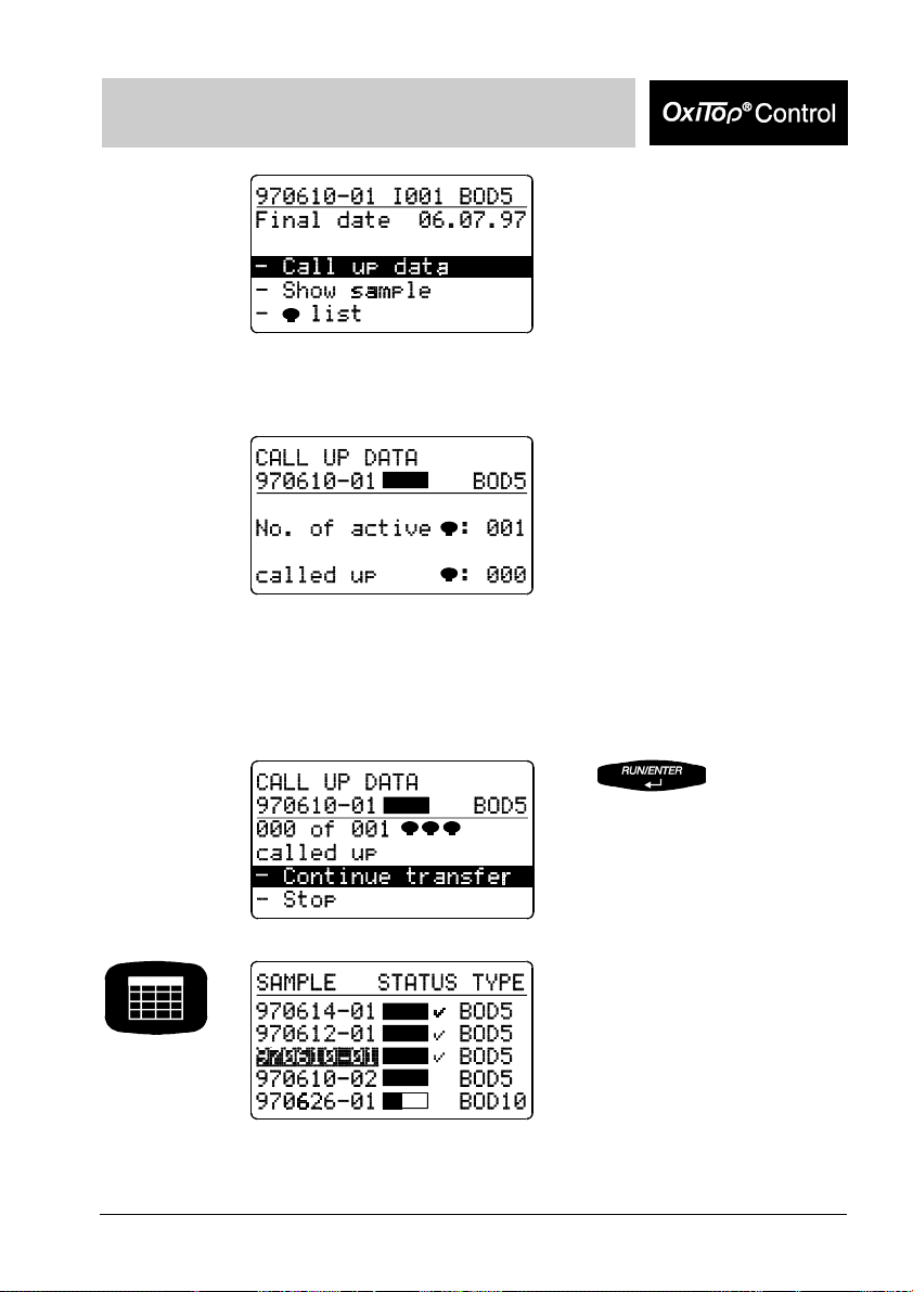
If all the measuring heads do not respond in the 1st pass of the data query, the
controller searches for the missing measuring heads for approximately a further 7
seconds in the scanner mode. Without having to press another key, you can continue
the data queries at other locations (e.g. other stirring platforms or other thermal
cabinets). Approximately 7 seconds after the last call up was performed, the scanner
mode breaks off automatically and the following display appears:
Point the controller at the measuring
heads:
“Continue transfer“ (preselected):
A new pass is made only for
measuring heads that have not
yet responded.
Stop: The instrument returns to
the entry menu.
For information on searching for
missing measuring heads, see
the chapter “What to do if...“
40 cm to 100 cm
The call up of further measuring
heads takes place in the scanner
mode.
Message that the data of all
measuring heads has been
called up. The instrument
subsequently returns to the input
menu.
16 BA31114e5 07/2006 BA31114e5 07/2006 17
Page 17
Operating Mode: Routine BOD
Immediately after the data call up of the complete measurement data records of a
finished measuring head, this measuring head is set to the “free“ status. The
measuring head is now available for a new measurement. The sample allocated in
the sample management is “finished“ (see the chapter “Sample management”).
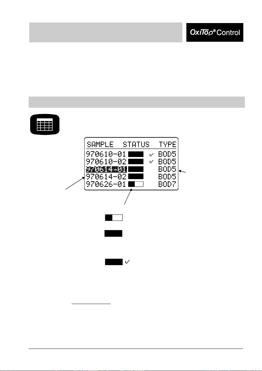
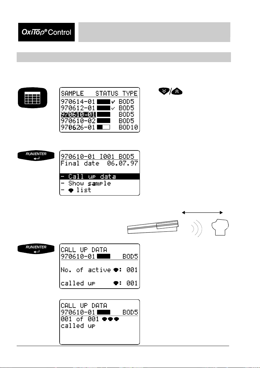
Sample management
Entry into the sample management.
A list of samples appears in the display (if samples are available):
BOD type and
run-duration
Sample number:
Date (YY/MM/DD)
and consecutive
number
Data of samples that have been started in the standard BOD operating mode, are not
listed in the routine BOD operating mode.
Reporting order:
- At the upper end of the list: finished samples (if available)
- Under this: running samples
Sorting of the samples: according to date and
sequential number 01 ... 99 from the oldest to the newest sample.
Temporal process of the sample:
Status bar partly filled:
The sample is not yet ready.
Status bar filled:
The ready and complete data set
of the sample can be called up from
the measuring head.
Status bar filled plus hook:
The sample is ready. The complete data
set is given in the controller for evaluation.
Page 18
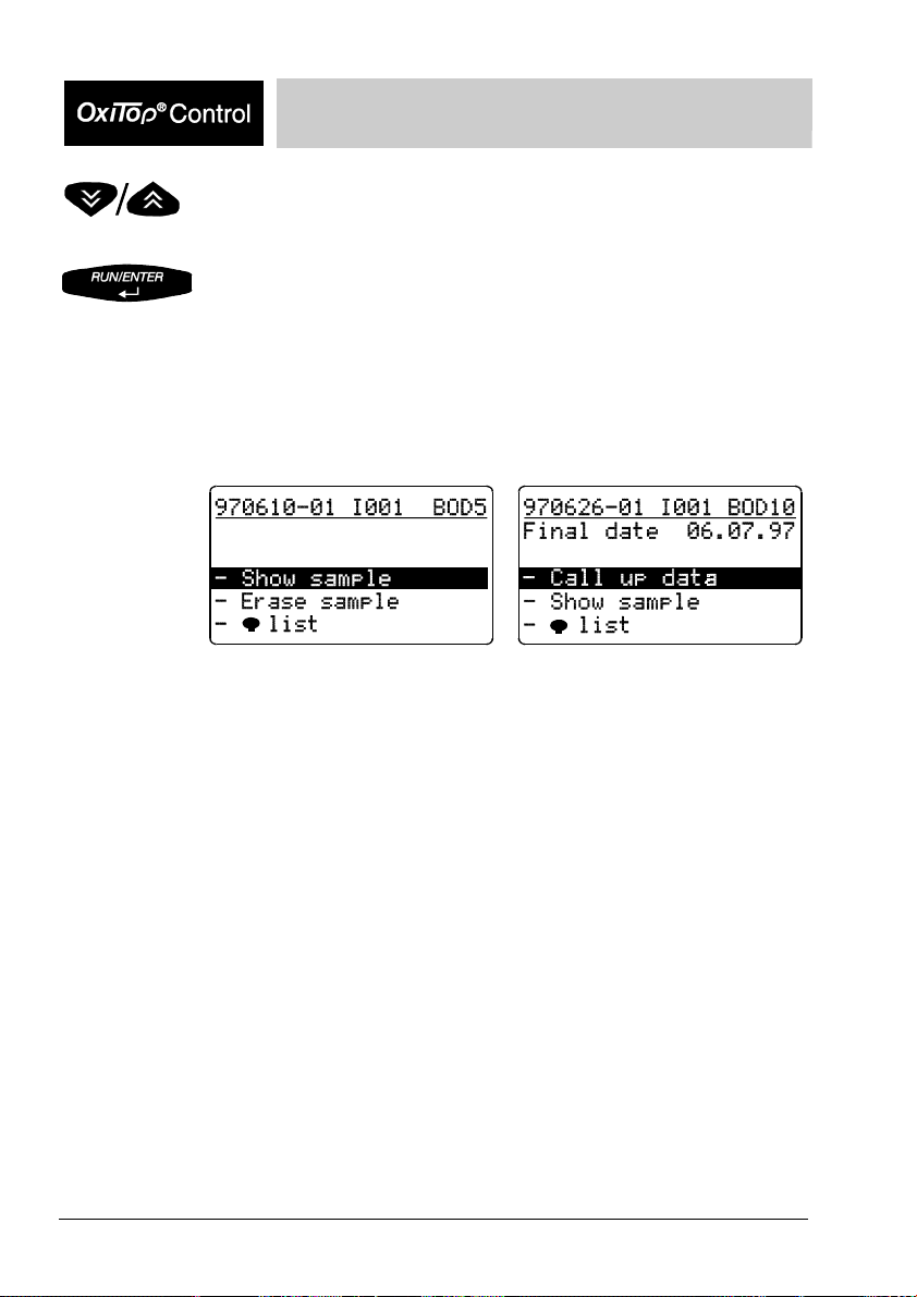
Operating Mode: Routine BOD
Select a sample.
Depending on the sample selected, one of the two following menus
appears. The header line contains the:
- sample number
- Id number (e.g. I001)
- BOD type and run time
of the selected sample.
Finished sample
Current sample
18 BA31114e5 07/2006 BA31114e5 07/2006 19
Page 19
Operating Mode: Routine BOD
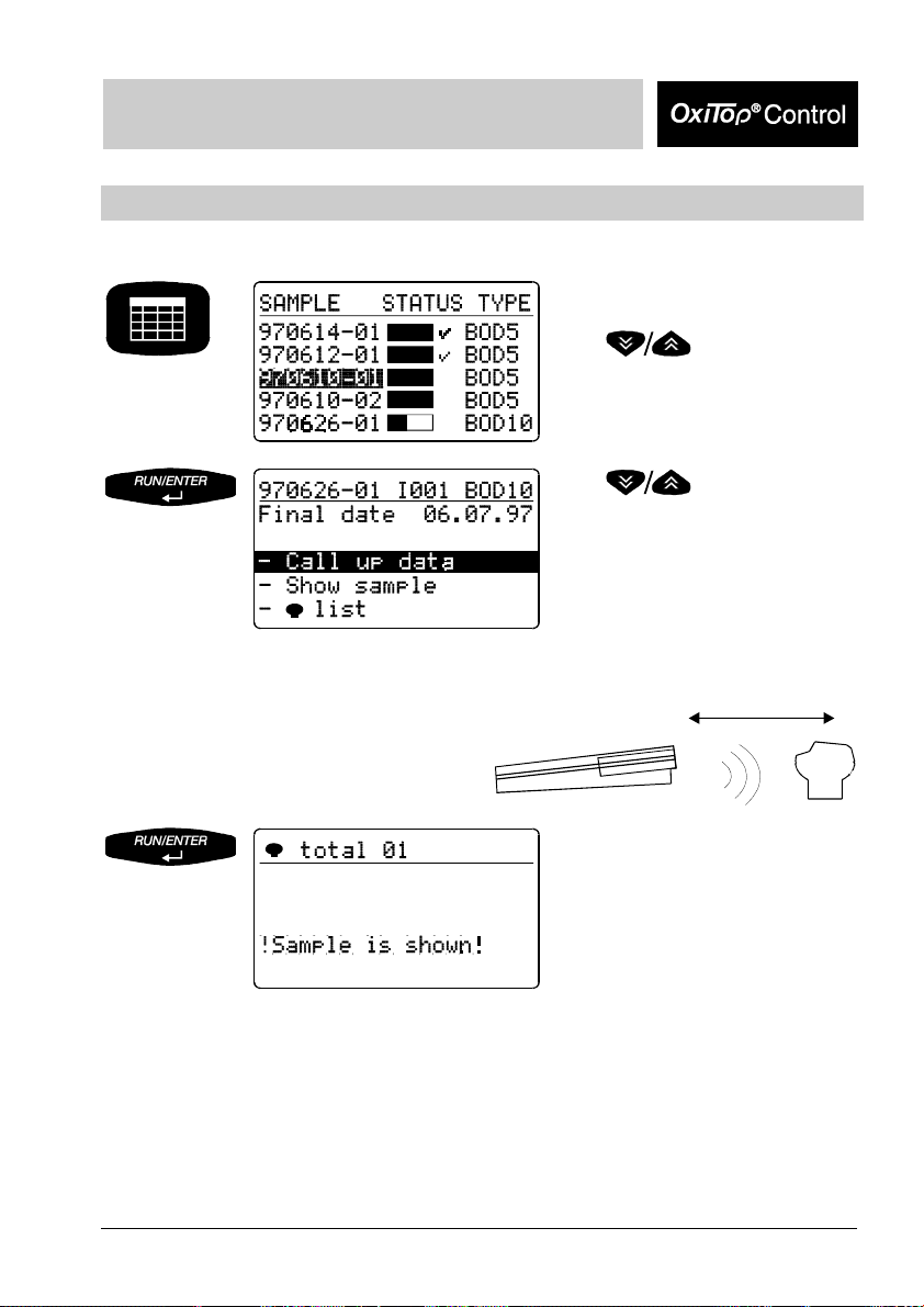
Show sample
This function is used to find the measuring heads. A sample labeling is not necessary.
Starting point: sample
management .
Point the controller at the measuring
heads:
Use
to select a sample.
Use
to select “Show sample“.
40 cm to 100 cm
The controller transmits the call
up of the selected sample. The
allocated measuring head flashes
for approx. 5 seconds.
After the message, the controller automatically returns to the
previous menu.
Page 20
Operating Mode: Routine BOD
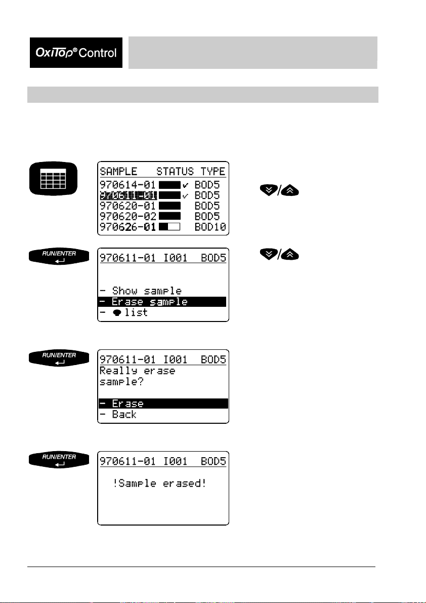
Erase data of finished samples
This function erases the data of finished samples from the sample management of the
controller. You can only erase a sample if it is finished; in non-finished samples, the
menu item “Erase sample“ does not appear.
Starting point: sample
management .
Use
to select a finished sample.
Use
to select the “Erase sample“
submenu.
Safety query with possibility to
return.
The sample has been erased.
After the message, the controller automatically returns to the starting
menu, “Sample management“.
20 BA31114e5 07/2006 BA31114e5 07/2006 21
Page 21
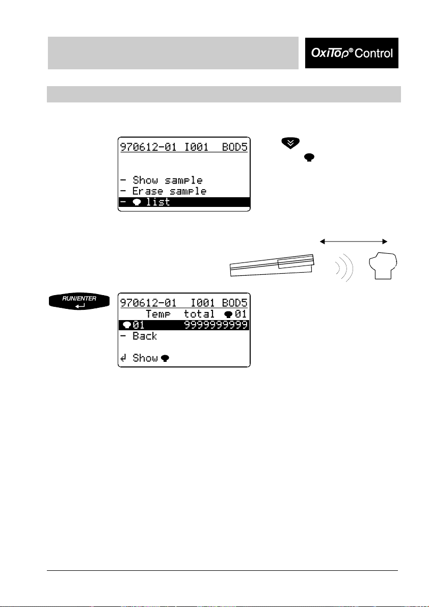
Operating Mode: Routine BOD
Show measuring head list
This function is used to allocate a measuring head to the relevant sample.
Point the controller at the measuring
heads:
Use
to select “ list“.
“List“, i.e. a measuring head is
displayed together with the serial
number of the measuring head.
The controller transmits the call
up of the selected sample. The
allocated measuring head flashes
for approx. 5 seconds.
40 cm to 100 cm
Page 22
Operating Mode: Routine BOD
Call up data
This function is used to call up the data of individual measuring heads. To call up the
data of all measuring heads, see the chapter “Call up all data“.
Use
to select a sample whose
- run time is not yet completed
(bar not yet full)
- data after complete
measurement that has not yet
been called up
(bar full, no tick)
Jumps to the submenu of the
selected sample.
Preselected: “Call up data“
Point the controller at the measuring
heads:
40 cm to 100 cm
Call up the measuring head
allocated to the sample in the
scanner mode:
The controller
- stores the data obtained
- updates the lists of the
sample management
The controller confirms the call
up performed.
22 BA31114e5 07/2006 BA31114e5 07/2006 23
Page 23
Operating Mode: Routine BOD
If the measuring head does not respond, the following display appears:
The controller then returns
automatically to the submenu.
The controller continues to search for the measuring head in the scanner mode.
Without pressing any further keys, the data call up can be continued at other
locations (e.g. other stirring platforms or other thermal cabinets). After approx. 7
seconds, the scanner mode automatically breaks off and the following display
appears:
Use to restart the
call up of the data (see above).
Return to the main menu,
“Sample management“.
Samples that were called up and
completed appear with a tick next
to them.
Page 24
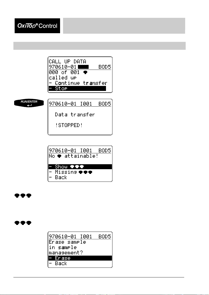
Call up data - Stop
Operating Mode: Routine BOD
If a measuring head is missing or
defective and the controller
cannot transfer the data as a
result, the menu item “Stop“ is
provided.
After confirmation, the display
message shown here appears.
Then:
“Show
“Missing
“:
“:
As in “Show sample“ but used selectively for missing measuring
heads (identification option if only the sender of the measuring head
is defective. Otherwise identify missing measuring heads using
“Show all“ (see the chapter “GLP/Tools”).
Using this you can remove the data of a missing or defective
measuring head from the sample management of the controller.
Erase:
Removes missing samples from
the data stock.
Return:
Jumps back to the previous
menu.
24 BA31114e5 07/2006 BA31114e5 07/2006 25
Page 25
Operating Mode: Routine BOD
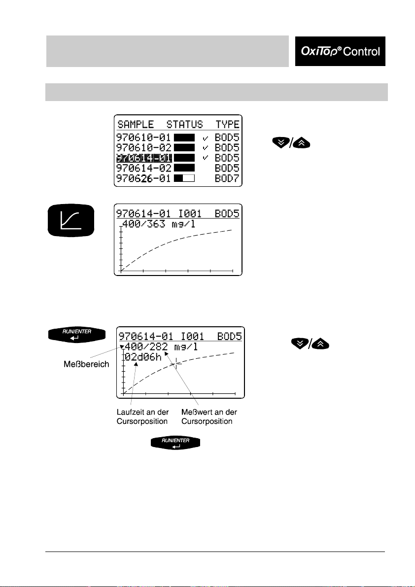
Evaluation
Change to cursor prompt:
Starting point: sample
management.
Use
to select a sample.
Enters into the evaluation:
Display of the selected sample as
a curve together with measured
value data.
Pressing causes the
cursor (crosswire) to run through
the points of the curve. The
allocated run time and the
corresponding measured value
are each displayed.
Pressing
display of the curve together with the measured value data.
changes between the cursor prompt and
Page 26
Operating Mode: Routine BOD
Curve display of samples that are too cold
Display of a curve
In using samples that are too cold, the maximum AutoTemp time is not sufficient to
reach the temperature adaption of the sample: By warming the sample, excess
pressure can result.
Display: Negative values of the curve are truncated and the curve emerges from
the time axis but not from the origin.
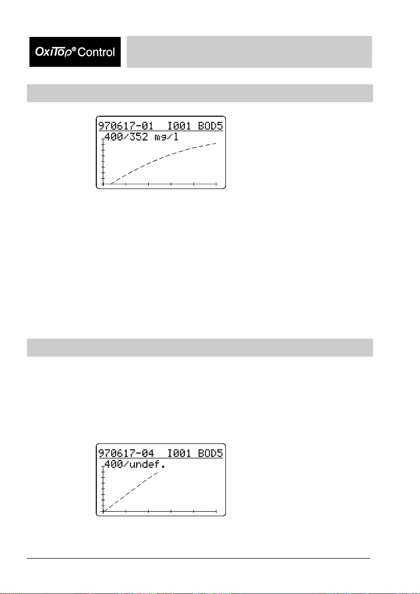
Measured values outside the measurement ranges
In the following cases, the evaluation displayed is not the measured value but “undef.“
(undefined):
- The measurement curve exceeds the measurement range at some point of its path.
- The measurement curve undercuts the measurement range at its end point.
Sample displays:
The measured value exceeds the
measurement range (overflow).
26 BA31114e5 07/2006 BA31114e5 07/2006 27
Page 27
Operating Mode: Routine BOD
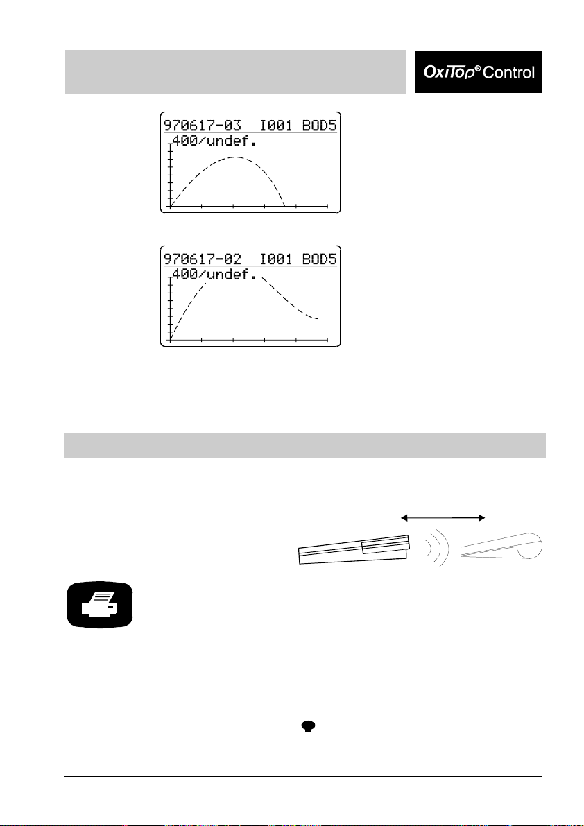
The measured value undercuts
the measurement range
(underflow).
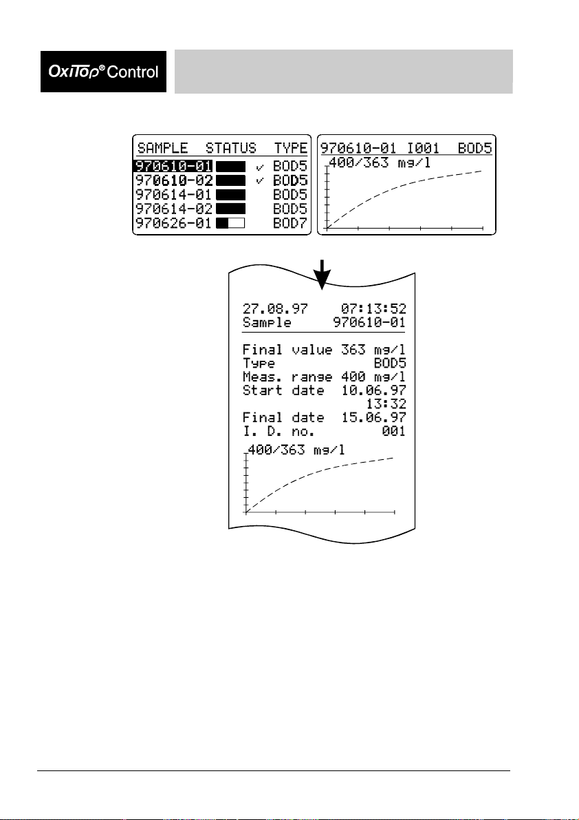
Printing
Point the controller at the printer:
Switch on the TD 100 IR printer.
The controller outputs the report data of the selected sample on the
IR interface.
Printout of:
- sample information
(start date and time, final date, type, measurement range,
identification number)
- curve + BOD final value
- report printouts: - current settings
- start information
-
- controller info
The measured value temporarily
leaves the measurement range.
10 cm to 100 cm
info
Page 28
Operating Mode: Routine BOD
From the sample management: From the evaluation:
28 BA31114e5 07/2006 BA31114e5 07/2006 29
Page 29
Operating Mode: Standard BOD
Operating mode: Standard BOD
Sample preparation
See WTW application reports
(contained within the scope of delivery of the accessories supplied).
Screw the OxiTop
and close them tightly.
Important note:
Never use joint grease or other lubricant for your OxiTop
heads. Some of these products contain solvents that can cause severe damage
to the plastic housing.
The sealing of the BOD bottles is also perfectly adequate without grease.
However, you should always wipe off heavy contamination and particles on the
sealing surfaces of the rubber sleeves and OxiTop
liability for damage due to the use of joint grease.
Start the measurement
To change to the operating mode BOD Standard refer to chapter GLP/Tools Settings - Operating mode.
-C measuring heads onto the sample bottles
-C measuring
-C. WTW accepts no
“Communication with the
measuring heads” mode.
Preselected: “Start sample”.
Use
to select the measurement range.
The filling volume required is
given in the right hand column.
The controller stores the setting
(memory function: the last
selected measurement range is
set).
Page 30
Operating Mode: Standard BOD
Additional information:
Type of measurement, run time, measurement range, final date, Id
number.
“Temp“ display => the AutoTemp function (see the chapter
“GLP/Tools”) is switched on.
Change the Id number for the additional identification of the sample
(e.g. extraction location) as follows:
- Use
- Press and
- Use
(setting range 001 ... 255).
- Use
to move the cursor to the Id number,
to set the Id number required
to confirm this.
Confirm the selected
measurement range for the
sample. The automatically
assigned sample number
(YY/MM/DD and sequential
number) is given in the header
line.
Use
possible (see the chapter “Standard BOD - Print”).
to print out the entire sample information
Confirm the start of
measurement.
Contact selection:
30 BA31114e5 07/2006 BA31114e5 07/2006 31
Page 31

Operating Mode: Standard BOD
The controller repeatedly sends the start information in the scanner
mode until successful feedback is received from the OxiTop®-C
measuring head. After the successful start message from the
measuring head:
Displays “!Started!”. From this
point in time, the sample exists
within the sample management.
Subsequently, the request to
start the next measuring head is
made automatically.
Start the next measuring head
2).
(
Contact selection:
The number of the measuring
head is automatically
incremented.
The controller continues to work with the stirring selection, i.e. you
can now start a sequence of measuring heads (parallel sample start)
without having to press any further keys by holding the controller to
the next measuring head to be started.
When all the measuring heads provided for this sample have been started:
Use
The controller returns to the input menu.
to selecct “Stop start”:
If no measuring head is started (e.g. because the controller was not held to - or not
close enough to - a measuring head):
Page 32

Operating Mode: Standard BOD
The start was stopped.
Use
If an attempt is made to start a measuring head that was already
started:
“Continue
controller to a measuring head
(see above).
Select “Stop start” to return to
entry level menu.
Displays “Measuring head
already used!”
Use
” and hold the controller to a
free measuring head (see
above).
to confirm
start” and hold the
to confirm “New
Select “Stop start” to return to
entry level menu.
In the delivery state, the controller automatically makes space when
“Start
it deletes the oldest finished sample (if a finished sample is
available). You can change this setting in “manual erase” (see the
chapter “GLP/Tools - Settings”).
” is selected if the measured value memory is full. To do this,
Call up all data
This function is used to call up the data of all measuring heads.
To call up the data of individual measuring heads: see the chapter “ Sample
management”.
Entry menu “Communication with
the measuring heads“.
32 BA31114e5 07/2006 BA31114e5 07/2006 33
Page 33

Operating Mode: Standard BOD
Use
to select “Call up all data”.
Point the controller at the measuring
heads:
40 cm to 100 cm
Queries the data of all active
measuring heads in the scanner
mode.
The controller stores the data
obtained and updates the list of
the sample management.
Duration of a pass: approx. 3
seconds for 12 measuring heads
in a stirring system.
If the measuring heads do not all respond in the 1st pass of the data query, the
controller searches for the missing measuring heads in the scanner mode for
approximately a further 7 seconds. Without having to press another key, you can
continue the data queries at other locations (e.g. other stirring platforms or other
thermal cabinets). Approximately 7 seconds after the last call up was performed, the
scanner mode breaks off automatically and the following display appears:
“Continue transfer“ (preselected):
A new pass is made only for
measuring heads that have not
yet responded.
Stop: The instrument returns to
the entry menu.
For information on searching for
missing measuring heads, see
Page 34

Operating Mode: Standard BOD
Point the controller at the measuring
heads:
the chapter “What to do if...“
40 cm to 100 cm
The call up of further measuring
heads is performed in the
scanner mode.
Message that all the data of all
the measuring heads has been
called up. The instrument then
returns to the input menu.
Immediately after the data transfer of the complete measurement data records of a
finished measuring head, this measuring head is given the “free” status. The
measuring head can be used for a new measurement. The relevant sample in the
sample management is marked as finished (see the chapter “Sample management”).
34 BA31114e5 07/2006 BA31114e5 07/2006 35
Page 35

Operating Mode: Standard BOD
Sample management
Entry into the sample management.
A list of samples appears in the display (if samples are available):
Data of samples that have been started in the standard BOD operating mode is not
listed in the routine BOD operating mode.
Reporting order:
- At the upper end of the list: finished samples (if available)
- Under this: current samples
Sorting of the samples: according to date and
sequential number 01 ... 99 from the oldest to the newest sample.
Select a sample.
Page 36

Operating Mode: Standard BOD
According to the sample selected, one of the two following menus
appears. The header line contains the:
- sample number
- Id number (e.g. I001)
- BOD type and run time
of the selected sample.
Finished sample
Current sample
Show sample
This function is used to find the measuring heads or samples. Sample labeling is not
necessary.
Starting point: sample
management .
Use
to select a sample.
36 BA31114e5 07/2006 BA31114e5 07/2006 37
Page 37

Operating Mode: Standard BOD
Point the controller at the measuring
heads:
40 cm to 100 cm
The controller transmits the call
up of the selected sample. The
allocated measuring head flashes
for approx. 5 seconds.
After the message, the controller automatically returns to the
previous menu.
Erase data of finished samples
This function erases the data of finished samples from the sample management of
the controller. You can only erase a sample if it is finished; in non-finished samples,
the menu item “Erase sample“ does not appear.
Starting point: sample
management .
Use
to select a finished sample.
Use
to select the “Erase sample“
submenu.
Page 38

Operating Mode: Standard BOD
Safety prompt with possibility to
return.
The sample has been erased.
After the message, the controller automatically returns to the starting
menu, “Sample management“.
Show measuring head list
This function is used to allocate individual measuring heads to the relevant sample in
the sample management and to find individual measuring heads.
Use
to select “Measuring head list”.
38 BA31114e5 07/2006 BA31114e5 07/2006 39
Page 39

Operating Mode: Standard BOD
Point the controller at the measuring
heads:
List of measuring heads of the
selected sample is displayed
together with the serial numbers
of the measuring heads.
40 cm to 100 cm
Use
confirm.
The controller again transmits the call up of the selected sample.
The measuring head flashes for approx. 5 seconds.
Use
to select the measuring head and use to
to return to the sample management.
Call up data
This function is used to call up the data of individual samples. To call up the data of
all samples, see the chapter “Call up all data“.
Use
to select a sample whose
- run time is not yet completed
(bar not yet full)
- data after complete
measurement that has not yet
been called up
(bar full, no tick)
Page 40

Operating Mode: Standard BOD
Point the controller at the measuring
heads:
Jumps to submenu of the
selected sample.
Preselected: “Call up data“
40 cm to 100 cm
Sequential call up of the
measuring heads allocated to the
sample (in this example: 7) in the
scanner mode:
The controller
- stores the data obtained
- updates the list of the
sample management
Duration of a pass:
approx. 3 seconds for 12
measuring heads in a stirring
system.
The controller confirms the call
up performed.
40 BA31114e5 07/2006 BA31114e5 07/2006 41
Page 41

Operating Mode: Standard BOD
The controller then returns
automatically to the submenu.
If the measuring heads do not all respond, the following display appears:
Renewed start of the data call up.
The controller continues to search for missing measuring heads in the scanner mode.
Without pressing any further keys, the data call up can be continued at other
locations (e.g. other stirring platforms or other thermal cabinets). Approximately 7
seconds after the last request was performed, the scanner mode automatically breaks
off and the following display appears:
Use to restart the
the data transfer (see above).
Immediately after the successful data transfer of a sample, the allocated measuring
heads are given the “free” status. The measuring heads can be used for a new
measurement.
Return to the main menu,
“Sample management“.
Transferred and completed
samples appear with a tick next
to them. (The complete
measurement data records of all
finished measuring heads of the
sample have been procured.)
Page 42

Call up data - Stop
Operating Mode: Standard BOD
If a measuring head is missing or
defective and the controller
cannot completely call up the
sample as a result, the menu
item “Stop“ is provided to stop
the data transfer.
After confirmation, the display
message shown here appears.
The sample is still running and
individual measuring heads of the
sample are not attainable.
Case 1
Three displays are then possible:
Case 2
The run time of the sample has
ended and the finished, complete
data of the attainable measuring
heads has been transferred.
42 BA31114e5 07/2006 BA31114e5 07/2006 43
Page 43

Operating Mode: Standard BOD
then
Case 3:
then
“Show
“Missing
”:
”:
Erase:
Removes missing measuring
heads from the data stock. The
completed sample is given the
“finished” status.
Back:
Jumps back to the previous
menu.
Abort using a function key: The
stopped sample is not declared
as “finished”.
No measuring head of a sample
is attainable.
Erase:
Removes a sample from the data
stock.
Back:
Jumps back to the previous
menu.
As in “Show sample“ but selectively for missing measuring heads
(Identification option if only the sender of the measuring head is
defective. Otherwise, see the chapter “What to do if...?”)
Only appears when the run time of the sample has expired. It is used
to set the sample to the “finished” status (ticked) if all the other
measuring heads are already “finished”: Erases the missing
measuring heads from the sample management.
Page 44

Evaluation
Operating Mode: Standard BOD
Starting point: Sample
management.
Use
sample.
to select the
Printout of the results with
curves.
Evaluation of the whole sample:
Display of all the curves together
with mean value data.
Check the display for outliers.
Printout of the results with curves
(according to printing format see the chapter “Print“)
Example: Whole sample with
outliers.
Scroll through the parallel
samples: Display of individual
curves (cyclical pass) with data of
the BOD final value.
Printout of a single result with a
single curve.
44 BA31114e5 07/2006 BA31114e5 07/2006 45
Page 45

Operating Mode: Standard BOD
Sample statistics
When jumping to the pull-down menu from “Show all curves“, the
menu item “Exclude curve“ disappears.
Results of the finished sample: Data of the current sample:
Starting point: display of a single
curve.
Changes to sample statistics.
The menu selection shown here
only appears if n (the number of
measuring heads) is at least 2.
If n = 1, see the chapter “Routine
BOD - Evaluation”.
- mean value
- SD: standard deviation
(from n = 3)
- n: number of measuring heads
- end date
- current mean value
- n: number of measuring heads
Printout of the results with curves
Printout of the data (current
mean value, n, sample
information) with curve paths to
date
Page 46

Operating Mode: Standard BOD
Excluding a curve
This function is used to temporarily exclude a single curve (e.g. an outlier) from the
evaluation and averaging of a whole sample.
The curve is only excluded temporarily! The data stock of the sample
management does not change. The excluded curve is present again when the call is
repeated.
The function “List of measuring heads“ (see the chapter “Sample management”) is
used to find leaky or defective single samples.
Display of the single curves:
Select curve.
:
Change to
“Exclude curve“.
“Exclude curve“
is preselected.
“Return“: Returns to the previous
menu.
46 BA31114e5 07/2006 BA31114e5 07/2006 47
Page 47

Operating Mode: Standard BOD
Message
“Curve excluded“.
Updated display
(curve excluded, mean value
newly calculated).
Printout of the updated results
with curves
(without the excluded curve).
Page 48

Operating Mode: Standard BOD
Cursor interrogation
Starting point:
Display of a single curve with
measured value data.
Use
to change to “Cursor query“.
Or from the display of all the single curves:
Use
to run through the curve values.
Use
current display.
Use to run through
the curve mean values.
to print out the
Use to print out the
current display.
Return to the previous menu using
Return to the display of all the single curves using
.
.
48 BA31114e5 07/2006 BA31114e5 07/2006 49
Page 49

Operating Mode: Standard BOD
Curves display for cold samples
Display of a single curve.
When using samples that are too cold, the maximum AutoTemp time is not sufficient
to reach the temperature balance of the sample: Warming the sample can cause
excess pressure.
Display: Negative values of the curve will be truncated and the curve arises
from the time axis but not the origin.
Display of all curves.
Page 50

Operating Mode: Standard BOD
Measured values outside the measuring range
In the following cases, “undef.“ (undefined) is displayed instead of the measured
value or mean value during evaluation:
- A measured curve exceeding the measuring range at any point of its path.
- A measured curve undercutting the measuring range at its end point.
After the exclusion of the defective curve (see chapter “Exclude curve“), the controller
displays the mean value again.
Sample displays:
A measured value exceeding the
measuring range (Overflow).
A measured value undercuts the
measuring range (Underflow).
A measured value temporarily
leaves the measuring range.
50 BA31114e5 07/2006 BA31114e5 07/2006 51
Page 51

Operating Mode: Standard BOD
Print
Point the controller at the printer:
Switch on the TD100 IR printer.
10 cm to 100 cm
The controller outputs the report data of the selected sample to
the IR interface.
Printout of
- sample statistics (mean value, SD, n)
- sample information (type, running time, measuring range, start
date and start time, end date, identification no.)
- curve + BOD final value
- with GLP On: additional information on the system status
and list of the series nos. of the measuring heads allocated to
the sample
- If AutoTemp is switched on: note “AutoTemp on“
- Report printouts: - current settings
- start information
-
- controller info
From the sample management: From the evaluation (display of
info
all the curves):
Page 52

Operating Mode: Standard BOD
Print from the evaluation:
If the controller is located
- in the display of all the curves with cursor display or
- in the display of single curves with or without cursor query,
the printout shows a copy of the relevant display.
52 BA31114e5 07/2006 BA31114e5 07/2006 53
Page 53

GLP / Tools
GLP/Tools main menu
Main menu:
Use
Submenus of the GLP/Configuration:
Show free
Show settings The current settings are displayed here.
Setup point Preset
Operating mode Routine BOD
Routine BOD: Standard BOD:
BOD type and measuring
time
Date Current Current
Time Current Current
GLP: ON or OFF Off (fixed setting) On
Calibrating interval --- 12 months
Erase memory auto
AutoTemp: ON or OFF
Switch-off interval 5 minutes (fixed setting) 5 minutes
Language German German
This function is used to identify free measuring heads without
requiring sample labeling. Free measuring heads can be used to
start new samples.
(The table shows the settings in the delivery state):
BOD5 (5 days) BOD5 (5 days)
(automatic erase)
On (fixed setting) On
to select a submenu
Use
to change to the submenu
auto
(automatic erase)
Page 54

GLP / Tools
Settings
Check Show
Here you can undertake or change the following settings:
Operating mode
Measuring time
Date/time
* GLP; calibrating interval
Memory
* AutoTemp
* Switch-off interval
Language
(finished/all)
info (with report printout)
Controller info (with report printout)
Cal test
Pneumatic test
Maintenance Erase finished samples (in the controller - sample management)
Reset/release
* only in the standard BOD operating mode
Show free
Main menu, “GLP/Tools“.
The “Show free
is preselected.
“ menu
Press .
Point the controller at the measuring
heads:
40 cm to 100 cm
All free measuring heads flash for approx.
5 seconds.
54 BA31114e5 07/2006 BA31114e5 07/2006 55
Page 55

GLP / Tools
Show settings
The following example illustrates the presettings in the Standard
BOD operating mode.
Main menu, “GLP/Tools“.
Use to select
the “Show settings“ menu.
“Show settings“ menu: A list
containing the current settings is
displayed.
Use
to scroll through the list where
the scrolling stops at the
beginning and end of the list
In the “Show settings“ submenu:
Print out the whole list of current settings (as in the display).
Page 56

Settings
Operating mode
GLP / Tools
Main menu, “GLP/Tools“.
Use
to select the “Settings“ menu.
“Settings“ submenu:
Use
to select “Operating mode“.
Use to acknowledge
it and to select
between the operating modes,
Routine BOD and Standard BOD.
Confirm using
.
Return to the “Settings“ main
menu:
, then .
56 BA31114e5 07/2006 BA31114e5 07/2006 57
Page 57

GLP / Tools
Measuring time
Set the type and measuring time of the BOD measurement here.
“Settings“ submenu:
Use
to select the “Measuring time“
submenu.
Use
to set the days (1 to 99) or
hours (0.5 to 23).
Confirm using
Display:
preset measuring time.
Default on delivery: 5 days.
.
Date/Time
Set the date and time in the controller here (important for sample number allocation).
“Settings“ submenu:
Use
to select the “Date/Time“
submenu.
Page 58

GLP / Tools
Set each of the number blocks
underlaid in black using
.
Confirm and continue with
The measuring time of samples already started is not affected by a change of date
and time.
Set the day, month, year, hours,
minutes, seconds consecutively.
.
GLP
The GLP (Good Laboratory Practice) set of rules presents particular requirements
concerning test resource monitoring for the measuring systems implemented
(quality assurance).
The following points must be fulfilled to comply with the requirements of GLP,:
1. Documentation of the calibration intervals.
2. Reporting of the calibrations:
Identification no. of the measuring head/controller
Date and signature of the operator.
3. Determination of the calibration frequency and instructions for the
performance:
The frequency depends on the operating conditions and the data of the test plan.
The OxiTop
This mode inhibits measuring if the calibrating interval is exceeded.
As a result of these restrictions, the GLP mode effects a standardization of the
calibrating and measuring conditions that are indispensable for working from the
aspect of quality assurance.
®
Control system supports these standards using an add-on GLP mode:
58 BA31114e5 07/2006 BA31114e5 07/2006 59
Page 59

GLP / Tools
Switch the GLP function on or off (only in the standard BOD operating mode):
“Settings“ submenu:
Use
to select the “GLP“ submenu.
“GLP“ submenu.
“GLP“ is preselected.
,
Press
then use to select
either GLP “On“ or “Off“
Confirm using
.
GLP - calibrating interval (“Calinterval”)
Set the time period (1 to 36 months) here. When it expires, the instrument registers
that the next test resource monitoring of the measuring heads is due. After the
calibrating interval expires, measuring is blocked until the calibration is performed or
the GLP setting is set to “Off“.
If the end of the calibrating interval set up lies within the measuring time of a
measurement to be started, this measurement cannot be started.
“GLP“ submenu.
Use to select the
subitem, “Calinterval“.
Page 60

GLP / Tools
Press ,
then set the time period for the
calibrating interval (1 - 36
months) using
Default: 12 months.
Confirm by
.
.
Memory
Here, you can set whether the controller should automatically erase the oldest
finished samples if the memory is full to create space for new measurement data
(setting “auto“).
With the “manual“ setting, the message “Lack of memory! Erase finished samples!“ is
displayed if the memory is full (See chapter “What to do if ...?).
“Settings“ menu:
Use
to select the “Memory“ submenu.
Erase memory is preset to
“automatic“.
To change it:
Press
use to select between
automatic and manual and
use to acknowledge
it.
Return to the “Settings“ menu:
then
,
and
.
60 BA31114e5 07/2006 BA31114e5 07/2006 61
Page 61

GLP / Tools
AutoTemp
The AutoTemp function controls the automatic start of the measurement after
checking the temperature adaption.
The pretemperature regulation to the precise incubator temperature is
recommended but not essential. Recommendation: e.g. regulate the temperature
of the sample for BOD5 measurements from 15 °C up to 20 °C.
You can tightly close the sample bottle with the measuring head immediately and
start the measurement. The AutoTemp function then automatically triggers the start of
the actual measuring after checking the temperature adaption. The measuring time of
the AutoTemp phase (adaption phase plus the test phase) is added to the sample
measuring time selected in the settings.
Pretemperature regulation of the sample
With the AutoTemp function switched on and, adhering to the recommendation
according to the table, the error quota that results from the temperature adaption of
the sample to the incubator temperature, T
selected measurement range final value.
Measuring time of the
measurement
Recommended sample temperature at the start of the
1 day T
2 days T
3 days T
4 days T
5 ... 99 days T
BOD5 15°C ... 20°C
, is smaller than 1% of the
Incubator
measurement
-0.5K ... T
Incubator
-1K ... T
Incubator
-2K ... T
Incubator
-3K ... T
Incubator
-5K ... T
Incubator
Incubator
Incubator
Incubator
Incubator
Incubator
AutoTemp function in detail
The AutoTemp function is made up of the adaption phase and the test phase.
Adaption phase
The phase without evaluation of the pressure process. The duration of the adaption
phase is defined for the various measuring times according to the table.
The adaption of the microbiology to the characteristics of the sample is made in this
phase and small temperature deviations, too high and too low temperatures of the
sample, can be compensated.
Test phase
The phase in which the further pressure process direction in the sample bottle is
checked. The test phase is defined for various measuring times according to the
table. In this phase, the continuing temperature deviation can be compensated if the
temperature of the sample is too low.
Page 62

GLP / Tools
Sequence of the test phase:
With a further drop in pressure (consumption) or constant pressure after the adaption
phase, the pressure value at the end of the adaption phase is the starting point of the
measurement.
On a further increase of pressure following the adaption phase (the sample is still too
cold), the turning point of the pressure process at which the pressure increase
changes into a pressure drop, is the starting point of the measurement.
If no starting point is found (according to the procedure given in points 1 and 2) after
the termination of the AutoTemp phase (time limit exceeded), the last measuring point
of the AutoTemp phase forms the starting point.
This means that the BOD curve in the graphical evaluation does not emerge from the
coordinate origin at the zero time point. A sample that was too cold was started.
BOD measuring
time
0.5 to 23 hours Since the measurement times are very short, the system
1, 2, 3, 4, 5 days 14, 28, 42, 56, 70 minutes Maximum of 28, 56, 84, 112,
6 to 99 days
in a 1 day pattern
Switch the AutoTemp function on or off (only in the standard BOD operating mode):
Adaption phase duration Test phase duration
always suppresses the AutoTemp phase here even if the
AutoTemp function is switched on in the settings.
70 minutes Maximum of 140 minutes
140 minutes
“Settings“ menu:
Use
to select “AutoTemp“ submenu.
62 BA31114e5 07/2006 BA31114e5 07/2006 63
Page 63

GLP / Tools
AutoTemp is preset to “On“.
To change:
Press
and use to select
between AutoTemp “On“ and
“Off“ and
use
Return to the “Settings“ menu:
then
,
to confirm it.
.
Switch-off interval
The time interval after the last time a key is pressed can be set here. After this time
interval expires, the controller switches itself off to save energy. (Settings of 5 to 15
minutes are possible, only in the standard BOD operating mode.)
“Settings“ menu:
Use
to select the “Switch-off interv.“
submenu.
The switch-off interval is preset to
5 minutes.
To change it:
Press
use to set the no. of
minutes required and
again to confirm it.
Return to the “Settings“ menu:
then
,
and
.
Page 64

GLP / Tools
Language
Select the language here in which the displays of the OxiTop® Controller appear. The
controller has the following 5 languages stored in it (default German): German English - French - Italian - Spanish.
“Settings” menu:
Use
to select the “Language“
submenu.
The default language is
“German“.
To change this:
Press
use to set the
language required and
again to confirm it.
From now on the displays appear
in the selected language.
Return to the “Settings“ menu:
then
,
and
.
“Settings“ menu.
Return to the main menu,
“GLP/Tools“:
then
or
using
,
.
64 BA31114e5 07/2006 BA31114e5 07/2006 65
Page 65

Check
Show
GLP / Tools
Main menu, “GLP/Tools“.
Use
to select the
“Check“ menu.
“Check“ menu.
“Show
“ preselected.
Point the controller at the measuring
heads:
All the measuring heads that are addressed flash for 5 seconds.
“Show “ submenu.
Use to select between
“Show free
“Show all
“ and
“.
40 cm to 100 cm
Page 66

info
GLP / Tools
“Check“ menu.
Use to select “
info“.
The measuring head flashes and
a display appears on the
controller giving the following
information:
- serial number of the measuring
head,
- battery status
(OK/LOBAT/EMPTY!!),
- the next calibration date
(only in the measuring mode,
Standard BOD and GLP “On“
- status of the measuring head
(free/used/defective).
If the measuring head is “used“,
use to scroll through the
display of further information:
- start date
- final date
- sample number
- type and
- range for the measurement
Return to the “Check“ menu
using
Repeat the procedure for each
measuring head.
.
66 BA31114e5 07/2006 BA31114e5 07/2006 67
Page 67

GLP / Tools
If the measuring head does not respond, the following display
appears after approximately 7 seconds:
Controller info
The query was stopped.
You can select between
- continue query (see above) and
- Stop (return to the
“Check“ menu
“Check“ menu.
Use to select
“Controller info“.
The display shows the following
information:
- number of measuring heads for
which there is still memory
capacity
- status of the supply batteries
- status of the data backup
batteries
(OK/LOBAT).
Use
specification of the
- software version
- Ser.no.
(can differ from the example
shown here)
Return to the “Check“ menu
using
to scroll to the
.
Page 68

GLP / Tools
Cal test
The Cal test is used to test the sealing of the system measuring head - rubber
sleeve - sample bottle and the operability of the systems OxiTop
In the standard BOD operating mode with the “GLP ON” setting, the controller
indicates when the next Cal test is due after each set up calibration interval (see the
chapter “GLP/Tools - GLP”),.
To perform the test, you need the WTW test resource, OxiTop
209 333.
Sample preparation: see operating manual, OxiTop
®
PM test resource.
®
Control.
®
PM, order number
“Check“ menu.
Use to select “Cal
test”.
For information on the further handling of the sample up to the “finished” status: See
the chapter “Start”.
The Cal sample appears together with the other samples in the sample management.
The BOD type is “CAL“:
The instrument automatically
allocates the sample number (in
the header line).
The filling volume (164 ml) and
the type together with the run
time of 5 days are preset.
68 BA31114e5 07/2006 BA31114e5 07/2006 69
Page 69

GLP / Tools
Evaluation of the Cal test
In the standard BOD operating mode and GLP “On“:
Starting point: sample
management.
Use
to select the test sample.
Enter the evaluation.
Display of the selected sample as
a curve with measurement value
data.
Compare measurement values
with batch test value
(according to operating manual,
®
OxiTop
Now you can set a new
calibration date for the measuring
head with the controller.
- “Show “ (to find the relevant
measuring head):
Function and messages as
described in the chapter
“Sample management“.
- “Set cal date“ (appears only if
the Cal test is finished and the
controller is in the standard
BOD operating mode, GLP is
switched on and the test is
finished).
- see below.
- “Stop“: Return to the curve
display.
Use
to select “Set cal date“.
PM).
Page 70

GLP / Tools
The controller sets a new test
date in the measuring head. The
controller calculates the new test
date from the current date + the
check interval set up (see the
chapter “GLP/Tools - Settings GLP - Check interval”).
The controller displays the setting
of the calibration date.
If the date was not set successfully (e.g. because the controller was
not held to - or not held close enough to - the measuring head):
Repeat the procedure using
,
then continue as described
above.
70 BA31114e5 07/2006 BA31114e5 07/2006 71
Page 71

GLP / Tools
Pneumatic test
The pneumatic test tests the measurement precision of the measuring head. It says
nothing about the long-term impermeability of the system.
To perform the pneumatic test, you require the testing agent, OxiTop
order number 209 334).
The user interface of the controller guides you through the test:
“Check“ menu.
Use
menu item “Pneumatic test
®
PT (WTW
to select the
“.
Set the plunger of the siringe on
the OxiTop
5 scale parts.
Tightly screw the measuring
head to be tested onto the
OxiTop PT tesing agent.
®
PT testing agent to
(Exceeding the time causes a
return to the “Check“ menu“).
Page 72

GLP / Tools
Maintenance
(Exceeding the time causes a
return to the “Check“ menu).
The controller display shows the
result of the pneumatic test.
Use to return to the
“Check“ menu.
Main menu, “GLP/Tools“.
Use
to select “Maintenance“ menu.
Erase finished samples
Here you can erase the data of finished samples that is already evaluated or no
longer required in order to free memory in the controller.
Menu item “Erase samples“ is
preset.
72 BA31114e5 07/2006 BA31114e5 07/2006 73
Page 73

GLP / Tools
A submenu appears with the
selection:
- From sample no. (preselected)
- All
- Back (from the “Maintenance”
submenu)
The controller displays the list of
finished samples.
The oldest finished sample is
marked.
With , you can mark further
samples.
With
marking again.
The controller asks again if you
really want to erase the marked
samples from the memory.
, you can remove the
After confirmation, the display
message shown here appears for
2 seconds and then the controller
returns to the menu “Erase
finished samples“.
Page 74

GLP / Tools
In the selection of erase “All“ samples, the following display appears:
The controller asks again if you
really want to erase the samples
from the memory.
Further: See above.
If no finished samples are available in the memory, the following
display appears:
Reset/release
This function can be used to release measuring heads again that were unintentionally
started.
Caution: After carrying out the “Reset/release“, the data of the measuring head
is erased!
Use to select the
Reset/release
menu item.
74 BA31114e5 07/2006 BA31114e5 07/2006 75
Page 75

GLP / Tools
The serial number of the
measuring head and the sample
number appear on the display.
Press
release the measuring head.
(If you do not want to release the
measuring head, select and
confirm it with “Return“.)
if you want to
Display message: The release/
reset has been performed.
Repeat the process for each of
the measuring heads to be
released.
Display message when the last measuring head of a sample has
been released:
Use
Reset/release
to return to the
menu.
Page 76

RS232 interface
RS232 Interface
The RS232 interface is used for communication with the computer (PC).
The RS232 interface is provided solely for the implementation of the WTW software,
“Achat OC“ (WTW software “ACHAT OC“ and RS232 interface cable AK 540/B
available from 1998).
Brief information about the software “Achat OC” (requires Microsoft Windows)
• Downloads the sample management of the controller to the PC
• Comfortably displays the sample management together with additional information
on the screen
• Enables the selection of samples in the PC and transfers the measurement data
of the selected samples from the controller to the PC
• Creates files from the measurement data for further processing with tabular
calculation programs
RS232 interface
76 BA31114e5 07/2006 BA31114e5 07/2006 77
Page 77

Cleaning
Cleaning the sample bottles
See the WTW application report.
Cleaning the controller and measuring heads
• Do not use any solvent (such as alcohol or acetone)!
Use a soft, damp cloth and dilute soapy solution for cleaning.
•
Page 78

Power Supply
The OxiTop®-OC100 and OxiTop®-C instruments are battery-powered.
To ensure reliable operation, both instruments have a 2-stage battery status monitor
1st level = warning level : Batteries LoBat !
2nd level = error level : Batteries empty !
OxiTop
Economy circuit (automatic switch off)
The instrument switches off automatically following the last key actuation after expiry
of the set switch-off interval.
Switch-off interval:
• Routine BOD operating mode: preset to a fixed period of 5 min.
• Standard BOD operating mode: delivery state of 5 min.,
settings of 5...15 min. possible
Supply batteries
Batteries: 3 pcs, alkaline (alkaline manganese), size: Mignon, AA, AM3, LR6
These batteries ensure the energy supply of the OxiTop
Run time: > 100 h (approx. 1000 start-ups in normal use)
Supply batteries status signals
are given on switching on the instrument by display messages and a signal tone
or can be called up under “GLP/Tools - Check - Controller info”.
Display message
Supply
Battery/ies LoBat !
Please change !
Supply
Battery/ies empty!
Please change !
®
-OC100 controller
Note / Meaning
The warning appears for approx. 3 seconds.
The instrument then continues to run normally.
The instrument can still be safely operated within the
specifications.
When the message first appears, there is still a
running reserve available.
Please obtain new batteries and replace the old ones
!
The message appears for approx. 3 seconds.
The instrument then switches itself off.
The instrument can no longer be used.
The supply batteries must be replaced by new ones.
®
OC100.
78 BA31114e5 07/2006 BA31114e5 07/2006 79
Page 79

Power Supply
Changing supply batteries:
• Switch off the OxiTop
• Loosen the 4 screws underneath the housing using a Phillips screwdriver (see
).
figure
• Place the controller on the lower case.
• Remove the upper case and put it down to the right next to the lower case with
the display downwards (see figure
• Remove the supply battery holder from the fixing in the lower case and turn it
around.
• Remove the empty supply batteries.
• Turn the supply battery holder around again and place it in the fixing in the lower
case.
• Set the upper case on top of the lower case, turn the controller and tighten the
housing screws using the screwdriver (see figure
• Switch on the controller. The battery change was successful if no error message
appears concerning the supply batteries.
• It is recommended to use only brand name batteries of the type specified as
“Alkaline“. Using other types of battery can affect reliable functioning.
• The supply batteries have no influence on data integrity.
• Insert new supply batteries - 3 pieces, alkaline (alkaline manganese),
size: Mignon, AA, AM3, LR6).
Ensure that they are the right way round!
(The poles are marked in the supply battery holder)
Always replace the complete set of batteries.
®
-OC100 controller.
).
).
Page 80

Power Supply
Data backup battery
1 x lithium battery, CR2430, e.g. WTW type Batt/OxiTop
order no. 209 012. This battery ensures that your measurement data and the
instrument settings in the OxiTop
years
Data backup battery - status messages
are given on switching on the instrument by display messages and a signal tone
or can be called up under “GLP/Tools - Check - Controller info”.
Display message
Data protection battery/ies LoBat!
Please change !
®
- OC100 controller are saved. Run time: typically 4
Note / Meaning
The warning appears for approx. 3 seconds.
The instrument then continues to run normally.
The instrument can still be operated within the
specifications.
When the message first appears, there is still a
running reserve available. Please obtain new
batteries and replace the old ones.
,
80 BA31114e5 07/2006 BA31114e5 07/2006 81
Page 81

Power Supply
Changing the data backup battery:
• Evaluate and save all the measurement data.
Options available :
- print out the results, see the chapter on printing
- save the data in the PC using the software “Achat OC“, see the chapter
“RS232 interface”
- handwritten documentation of the results.
• Documentation of your instrument settings:
- printout of your instrument settings, see the chapter “GLP/Tools - Settings -
Show settings”.
• Switch off the OxiTop
• Loosen the 4 screws underneath the housing using a Phillips screwdriver (see
).
figure
• Place the controller on the lower case.
• Remove the upper case and put it down to the right next to the lower case with
the display downwards (see figure
• Remove the supply battery holder from the fixing in the lower case and turn it
around.
• Remove the empty data backup battery.
• Set the upper case on top of the lower case, turn the controller and tighten the
housing screws using the screwdriver (see figure
• Switch on the controller. The message “Please set the system clock!“ appears.
This message is a reminder and should be acknowledged by .
• The battery change was successful if no error message appears concerning the
data backup battery.
• Enter the current date/time and your settings.
• Insert the new data backup battery (1 piece, lithium battery, CR2430,
e.g. WTW type Batt/OxiTop
Ensure that the battery is the right way round!
The positive pole must be at the top.
®
-OC100 controller.
).
, order no. 209 012)
).
Page 82

Power Supply
OxiTop®-C measuring head
Supply batteries
Batteries: 2 x lithium batteries, CR2430, e.g. WTW type Batt/OxiTop
order no. 209 012
These batteries ensure the energy supply of the OxiTop
Run time: typically 2 years
®
The OxiTop
-C measuring head does not require any batteries for data backup.
Supply batteries status messages
- are given on starting the measuring head via the OxiTop
display messages and a signal tone
- can be called up in the menu “GLP/Tools - Check -
Display message
Batteries LoBat !
start
Note / Meaning
The instrument can still be safely operated within the
specifications.
The running reserve of the instrument is still sufficient for
the measurement to be started.
Please obtain new batteries and replace the old ones!
Battery/ies empty!
- New
- Stop
start
The instrument can no longer be used.
The supply batteries must be replaced by new ones.
It is possible to start a new measuring head or to
complete a sample start.
®
-C measuring head.
®
OC100 controller by
info”.
,
82 BA31114e5 07/2006 BA31114e5 07/2006 83
Page 83

Power Supply
Changing the supply battery
• Change the battery after the measurement has been terminated.
- Press in the snap-action holder.
- Open the upper case.
- Remove the batteries.
- Insert new batteries (2 x lithium batteries, CR2430, e.g. WTW type
Batt/OxiTop
way round!
- Insert the upper case with the lug in the locking pin (lower case).
Caution! Do not crush the cable connection!
- Close the upper case (let the hook snap into place).
Check if the battery change was successful:
“Batteries: OK“ must appear in “GLP/Tools - Check -
The batteries have no effect on the data integrity of the OxiTop
Disposing of the batteries
, order no. 209 012). Ensure the batteries are inserted the right
info”.
®
-C
Properly dispose of used batteries at a battery collection point.
Page 84

What to do if...?
Display messages
Messages
already
used !
Set system
clock !
defective !
No samples
available !
84 BA31114e5 07/2006 BA31114e5 07/2006 85
Explanations, causes and problem solutions
Cause:
• The selected measuring head has already been started
for a measurement and can only be used for a new
measurement after the current measurement is finished
and the measurement data completely retrieved.
Problem solutions:
• Select new and free measuring head or
• Stop
start or
• Release measuring head (chapter “Maintenance -
Release/reset”)
Cause:
Data backup battery was changed!
Problem solution:
Set the clock (see the chapter “GLP/Tools - Settings Date/Time”).
Causes:
The selected measuring head is defective.
Please send it to WTW.
Problem solutions:
• Select new and free measuring head or
• Stop
start
Cause:
There are no finished samples stored in the sample
management.
Problem solution:
• Transfer the unfinished samples of the sample
management to “finished” status.
To do this, the measurement data of all measuring heads
must be called up and evaluation and documentation of
the measurement data of the finished samples performed.
• If the measurement data of the measuring heads is not yet
finished, no instant remedy is possible!
The memory capacity limit of the instrument has been
reached.
Page 85

Messages
No active
Cal test
(example date)
!
due on 18.07.97!
What to do if...?
Explanations, causes and problem solutions
Causes:
• No measurement has been started.
• The measuring heads are placed at another location
(e.g. other levels in the incubator, other incubators,
further storage locations).
• The measuring heads have no optical contact with the
controller:
- Distance too great, angular position imprecise
- IR window of the measuring head averted from the
controller
- Shading by other objects.
• Controller defective
Problem solutions:
• Modification of the distances or angle
• Search other storage locations
• Check controller
• Test the measuring heads (see section
“Requirements/Problems“)
Causes
• GLP is switched on
• The test resource monitoring is due within the
measuring time of measurement for the selected
measuring head.
• Date/time is not correctly set in the controller.
Problem solutions
• Use another free measuring head that has been
checked
• Start the due measuring head with the Cal test (see
chapter “Check - Cal test”)
• Switch off GLP and start measuring head (if your
laboratory practice permits).
• Set the date/time in the controller.
Page 86

Messages
Lack of memory possible !
Memory for
free !
ContinueÃ
Memory lack !
No ready samples autom.
erasable!
11
What to do if...?
Explanations, causes and problem solutions
Cause:
This message is used as information in the standard BOD
operating mode.
There is a lot of sample data stored in the sample
management. The memory is almost full.
It is still possible to start a sample as a parallel sample start
with 11 measuring heads (the number 11
an example, possible numbers: 1...11
Problem solution, if necessary:
• Erase finished samples:
Chapter “GLP/Tools - Maintenance- Erase finished
samples”
• Alternative: Changing the instrument setting to
automatic erasing of finished samples:
Chapter “GLP/Tools - Settings - Memory - Erase: auto"
Cause:
The instrument works with the setting, Erase memory “auto“
(automatically). The memory is full and only unfinished
samples are stored in the sample management.
The instrument can only erase finished samples
automatically.
Problem solution:
• Transfer the unfinished samples of the sample
management to the “finished“ state.
• To do this, call up the measurement data of all
measuring heads and perform the evaluation and
documentation for the measurement data of the finished
samples.
• If the measurement data of the measuring heads is not
yet finished, no instant remedy is possible!
The memory capacity limit of the instrument has been
reached.
used here is
).
86 BA31114e5 07/2006 BA31114e5 07/2006 87
Page 87

What to do if...?
Messages
Memory lack !
Erase finished sample/s!
undef.
(Display in the curve
presentation or sample
statistics)
Explanations, causes and problem solutions
Cause:
• The instrument is working with the “manual“ setting of
Erase memory. The memory is full.
Problem solutions:
• Transfer the unfinished samples of the sample
management to “finished“ status
• Call up the measurement data of all the measuring
heads
• Perform evaluation and documentation of the
measurement data of finished samples.
• Erase finished samples from the sample management:
Chapter “GLP/Tools - Maintenance- Erase finished
samples”
Note: Only the finished samples in the sample
management are erased.
Causes:
• The selected measurement range has been exceeded.
• The sample filled was too warm.
• The AutoTemp function is switched off.
• The sample filled was very cold and has a low
consumption behavior (smaller BOD value).
• The system is not sealed
(bottle internal pressure = atmospheric pressure).
Avoiding the problem:
• Select the correct measurement range (see WTW
application report).
• Pretemper the sample more precisely.
• Switch on the AutoTemp function (only effective for
measuring times longer than one day).
• Check the system for leaks by means of visual checks:
Are the sealing surfaces of bottle and measuring head
clean and fault-free? Are there cracks in the sleeve,
bottle or measuring head?
• Perform “Cal test“ (see chapter “Check”).
• Check the incubator temperature.
Page 88

Messages
10 of 12
called up
(sample message,
no. is variable)
0 of 19
called up
(sample message,
no. is variable)
What to do if...?
Explanations, causes and problem solutions
Cause:
• Two measuring heads have not been found by the
controller
• The measuring heads are positioned at another location,
e.g. other levels in the incubator, other incubators,
further storage positions
• The measuring heads have no optical contact with the
controller:
- Distance too great, angular position imprecise
- IR window of the measuring head averted from the
controller
- Shading by other objects.
• The missing measuring heads are defective
Problem solutions:
• Modification of the distances or angle
• Search other storage locations
• Search for and check measuring heads (see section
“Requirements/Problems“)
Cause:
• No measuring head has been found by the controller.
• The measuring heads are positioned at another location,
e.g. other levels in the incubator, other incubators,
further storage positions
• The measuring heads have no optical contact with the
controller.
- Distance too great, angular position imprecise
- IR window of the measuring head averted from the
controller
- Shading by other objects.
• The controller is defective.
Problem solutions:
• Modification of the distances or angle
• Search other storage locations
• Check the controller (section “Requirements/Problems“)
88 BA31114e5 07/2006 BA31114e5 07/2006 89
Page 89

What to do if...?
Requirements / Problems
Requirements /
Problems
No or missing samples
in the sample
management
At the beginning of the
measurement, no
measurement curves
are displayed
Measurement curves
does not emerge from
the origin
No measurement
curves are displayed
although the
measurement has
already been running
for an extended period
of time
Search for free
measuring heads for a
new measurement
Procedure / Problem solutions
Cause:
• You started samples in the operating mode „BOD
Standard“. Then you switched over to the operating
mode „BOD Routine“.
Problem solution:
• Switch the instrument to the operating mode „BOD-
Standard“ (see chapter GLP/Tools - Settings - Operating
mode).
Causes:
• The sample filled and started was too cold.
• AutoTemp function is switched off.
Problem solution:
• Temper the sample more precisely.
• Switch on the AutoTemp function (only effective for
Causes:
• No data was retrieved from the measuring heads.
• The AutoTemp phase is still running
Problem solution:
• Call up the data of the measuring heads.
• Wait for the end of the AutoTemp phase then start the
Procedure:
Perform the function “Show free
(see chapter “GLP/Tools”).
The controller causes the free measuring positions to flash
for 5 seconds.
measuring times longer than one day).
(see the chapter ”AutoTemp function in greater detail“).
See chapter “Call up all data“.
evaluation.
“
Page 90

Requirements /
Problems
Measuring head
unintentionally started
for measurement
Measuring head
started with incorrect
settings
Measuring head is
required for another
sample
Search for the
defective measuring
head
A measuring head is
missing or is defective.
Requirement:
To determine the
corresponding sample
What to do if...?
Procedure / Problem solutions
Problem solution
The measuring head can be released again through the
command Reset/release:
Chapter “GLP/Tools
The controller guides you further through the operation.
If only one measuring head is stored under the
corresponding sample number (in the routine BOD
operating mode, this is always the case), the controller
automatically erases the sample in the sample
management.
Procedure:
• Perform a measuring head reaction test (see above).
A measuring head that repetitively shows no reaction to
the test is defective.
• If the defective measuring head cannot be established
in this way, perform the measuring head check (see
“Single check”). In doing this, each individual measuring
head must be checked until the defective measuring
head has been found.
Procedure:
Call up the function “Call up data” from the sample
management for each individual unfinished sample. The
corresponding sample can be determined by this.
For subsequent error handling, see the chapter “Sample
management - Call up data”.
- Maintenance - Reset/release “.
90 BA31114e5 07/2006 BA31114e5 07/2006 91
Page 91

What to do if...?
Requirements /
Problems
The precision and
sealing of the system
sample bottles plus
measuring head
should be checked
Measuring head check
(single check)
(To which running
sample does the
selected measuring
head belong?)
The measuring
precision of the
measuring head
should be checked.
Perform measuring
head reaction test
Procedure / Problem solutions
Procedure:
See the chapter “GLP/Tools
Procedure:
Single check method:
menu “GLP/Tools
• The controller guides you further through the operation.
• All single information on the state of the measuring
• The check can be undertaken at any time without
• If no reaction at all can be determined, the batteries
• The measuring precision cannot be checked with this!
Procedure:
Pneumatic test (PT) of the measuring head:
see the chapter “GLP/Tools
Procedure:
• Menu “GLP/Tools
• All optically attainable measuring heads must flash for
• The check can be undertaken at any time without
• This test only checks the reaction to commands.
• If no measuring head reacts, the controller should be
- Check - Cal test “
- Check - info”
heads is listed, i.e. the measuring head responds.
affecting the measurement that is running.
should be changed and the measuring head check
repeated.
- Check - Pneumatic test”
- Check - Show all ”:
approx. 5 seconds independent of their status.
affecting the measurement that is running.
checked.
Page 92

Requirements /
Problems
Checking the controller Problem solution:
Incorrect time display
on being switched on
Procedure / Problem solutions
Controller info
• See the chapter “GLP/Tools
All single information on the state of the controller is
listed.
• The check can be undertaken at any time without
affecting the measurement that is running.
• Perform the command: “Show all
“GLP/Tools
(The check is used in this case to test the IR interface.)
All working measuring heads must flash for 5 seconds.
• Perform a measuring head check - see the chapter
“GLP/Tools
case to test the IR interface). Here, a working
measuring head should supply its status data.
• Keyboard, display and signal tone should show the
required reaction.
• Check the function of the clock (prerequisite: clock is
available).
Switch off the instrument and switch it on again. Time
and date each appear showing the current values.
• Check RS232 interface (only required when using the
WTW software, ACHAT OC):
- Connect controller to your PC by means of the
interface cable AK540/B.
- Switch on controller and start the PC program,
ACHAT OC. In doing so, the PC program checks the
RS232 interface.
Cause:
• Data backup battery has been changed!
• Summer/winter time change has taken place.
Problem solution:
Set the clock (see the chapter “GLP/Tools - Settings Date/Time”)
What to do if...?
- Check - Controller info”
“. See
- Check - Show ”.
- Check - info” (The check is used in this
92 BA31114e5 07/2006 BA31114e5 07/2006 93
Page 93

What to do if...?
Requirements /
Problems
The IR printer does not
react
Procedure / Problem solutions
Causes:
• Printer is not switched on.
• The printer has no optical contact with the controller:
- Distance too great, angular position imprecise
- IR window of the measuring head averted from the
controller
- Shading by other objects.
• Printer batteries are empty.
• No paper or the wrong paper is loaded.
• Printing is not possible in the operating state of the
controller selected.
• The printer or the controller is defective.
Action:
• Switch on the printer
• Establish optical contact
• Check or change the printer batteries. Please read the
• Check in the operating manual of the controller whether
operating instructions of the printer.
printing is possible in the state selected.
Note: During printing, the message “Printing active”
always appears on the display.
Power supply / Battery status
For battery status messages, see the chapter “Power supply”.
Page 94

Accessories and spare parts
Accessories
See WTW General Catalog and WTW application reports.
Spare parts
Description Type Order no.
BOD bottle (Sample bottle, amber, contents 510 ml),
minimum order 3 pcs
Rubber sleeve, minimum order 3 pcs GK 600 209170
Stirrer bar, minimum order 3 pcs RST 600 209120
Stirrer bar remover REF 600 209130
2 bottles of sodium hydroxide pellets (of 50 g) NHP 600 209140
Nitrification inhibitor NTH 600 209331
Spare batteries (1 set) Batt/OxiTop
Spare OxiTop
®
-C measuring head OxiTop®-C 208830
PF 600 209100
®
209012
94 BA31114e5 07/2006 BA31114e5 07/2006 95
Page 95

Technical Data
OxiTop® OC 100 controller
Measurement ranges 0 ... 40/ 80/ 200/ 400/ 800/ 2000/ 4000 mg/l BOD
Run times and data sets Run time of the
measurement
Measurement period
Display LCD graphics display 64 x 128 pixels
Power supply Supply batteries: 3 pcs, alkaline (alkaline
Battery run time
Supply battery
Data backup battery
Safety class 3, equipment safety: IEC 1010, EN 61010 part 1
Protection type IP 41 DIN 40050
EMC
-Interference emission
-interference immunity
Climate class 2, VDI/VDE 3540
Ambient temperature Storage: -25°C ... +65°C
Dimensions 45 x 100 x 200 mm (H x B x T)
Weight approx. 390 g
Test certificates CE, TÜV, UL, CUL(UL/CSA)
Warranty 1 year
manganese), Size: Mignon, AA, AM3, LR6
Data backup battery: 1 x lithium battery, CR2430,
WTW order no. 209 012
> 1000 switchings in case of normal use;
(the instrument has an automatic shut off)
Typically 4 years
EN 50081-1, FCC Class A
EN 50082-1
Operation: +5°C ... +40°C
0.5 hours 180
1.5 hours 270
2.5 hours 300
3.5 hours 315
4.5 hours 324
5.5 hours 330
all whole hours
(1, 2, 3 to 23 hours)
all whole days
(1, 2, 3 to 99 days)
Data records
360
360
Page 96

Technical Data
OxiTop
Measuring principle manometric by means of a pressure measuring head
Measured of BOD
Pressure range
Accuracy ± 1% of measured value ± 0.7 % of the measuring
Resolution 1 hPa
Display LED pilot lamps
Power supply 2 x lithium batteries, CR2430, e.g. WTW type
Battery run time Typically 2 years, in case of normal use
Safety class 3, equipment safety: IEC 1010, EN 61010 part 1
Protection type IP 54 DIN 40050
EMC
-Interference emission
-interference immunity
Climate class 2, VDI/VDE 3540
Ambient temperature Storage: -25°C ... +65°C
Dimensions H: 70 mm, ∅∅∅∅ 70 mm
Weight 95 g
Test certificates CE, TÜV, UL, CUL(UL/CSA)
Warranty 1 year
®
-C measuring head
(oxygen drift according to DIN 38409 T 52)
500 ... 1350 hPa (mbar).
range
Batt/OxiTop
EN 50081-1, FCC Class A
EN 50082-1
Operation: +5°C ... +50°C
n
, order no. 209 012)
96 BA31114e5 07/2006 BA31114e5 07/2006 97
Page 97

Technical Data
Page 98

BA31114e05 07/2006 1
Page 99

Supplement to the operating manual
System OxiTop® Control
Controller
®
OxiTop
Measuring heads
OxiTop®-C
This sheet is a supplement to the present operating manual and
contains the chapter “Restore data“ and some notes.
Always keep this sheet together with the operating manual.
OC100
Page 100

Supplement to the operating manual
Restore data
In case you lost your controller or your controller is defective, the “Restore data“
function facilitates to restore the data of running measurements using a new or
another controller. This means the data are not lost.
To perform this function the memory of the controller must be absolutely
empty. The data of each single measuring head are restored one after
the other in a sequence. It is not possible to leave this function and to
continue it afterwards because then the memory would no longer be
empty.
Use to select the
“Restore data“ submenu.
Confirm the restoration for one
measuring head and hold the
controller to the measuring head.
Contact selection:
The controller displays the serial
number of the selected
measuring head.
2 BA31114e05 07/2006 BA31114e05 07/2006 3
 Loading...