

Page 1

INSTRUCTION MANUAL
IM055
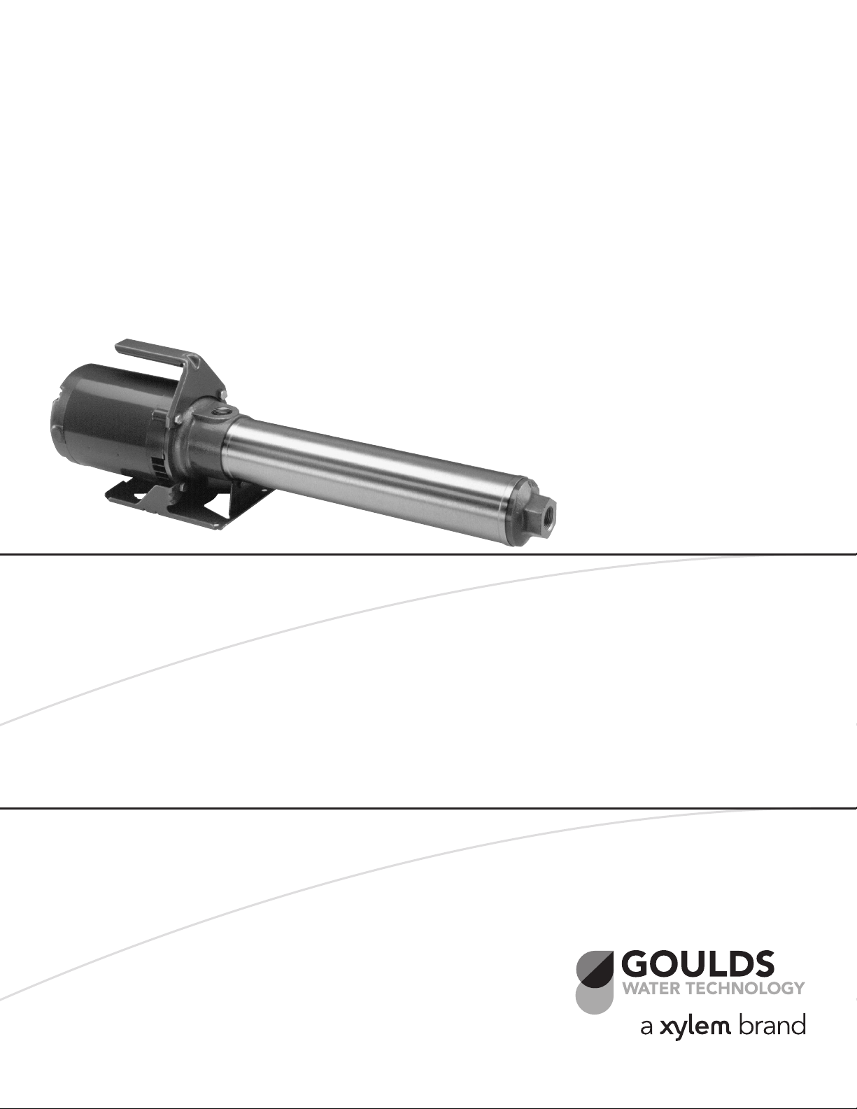
Model GB
INSTALLATION, OPERATION AND MAINTENANCE INSTRUCTIONS
Page 2
SUBJECT PAGE
Safety Instructions ........................................................................................................................................................ 3
Engineering Data .......................................................................................................................................................... 3
Piping ........................................................................................................................................................................... 3
Wiring and Grounding ................................................................................................................................................. 3
Rotation ....................................................................................................................................................................... 3
Operation ..................................................................................................................................................................... 4
Maintenance................................................................................................................................................................. 4
Disassembly .................................................................................................................................................................. 4
Reassembly ................................................................................................................................................................... 4
Troubleshooting ........................................................................................................................................................... 5
GB Components Parts Table ......................................................................................................................................... 6
Limited Warranty ......................................................................................................................................................... 7
Declaration of Conformity ......................................................................................................................................... 21
Pump Model Number:
Pump Serial Number:
Dealer:
Dealer Phone No.:
Date of Purchase:
Date of Installation:
Current Readings at Startup:
1 Ø 3 Ø L1-2 L2-3 L3-1
Amps: Amps:
Volts: Volts:
2
Page 3
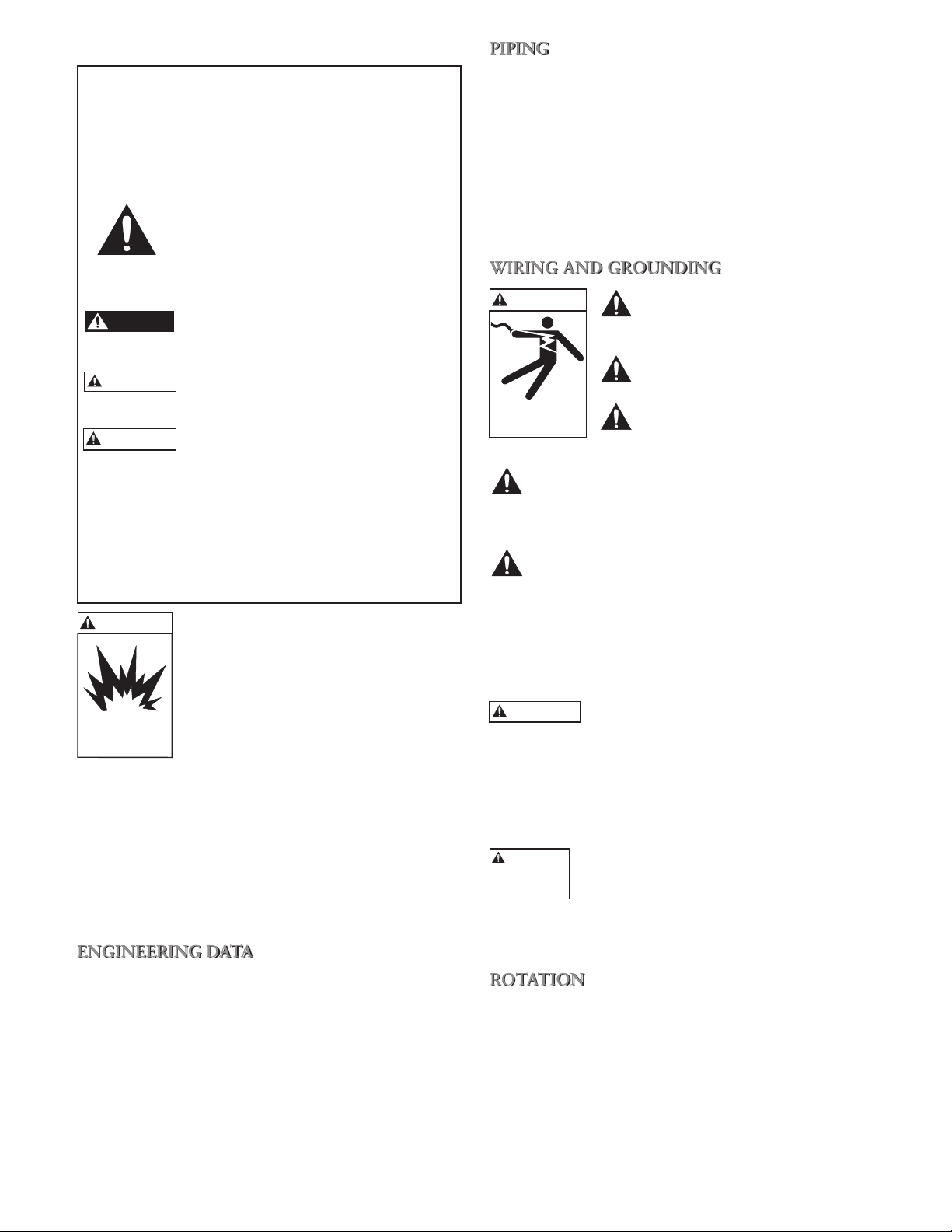
SAFETY INSTRUCTIONS
DANGER
WARNING
CAUTION
WARNING
Hazardous fluids
can cause fire,
burns or death.
WARNING
WARNING
Hazardous voltage
can shock, burn or
cause death.
TO AVOID SERIOUS OR FATAL PERSONAL
INJURY OR MAJOR PROPERTY DAMAGE, READ
AND FOLLOW ALL SAFETY INSTRUCTIONS IN
MANUAL AND ON PUMP.
THIS MANUAL IS INTENDED TO ASSIST IN THE
INSTALLATION AND OPERATION OF THIS UNIT
AND MUST BE KEPT WITH THE PUMP.
This is a SAFETY ALERT SYMBOL.
When you see this symbol on the pump
or in the manual, look for one of the following signal words and be alert to the
potential for personal injury or property
damage.
Warns of hazards that WILL cause
serious personal injury, death or major
property damage.
Warns of hazards that CAN cause
serious personal injury, death or major
property damage.
Warns of hazards that CAN cause personal injury or property damage.
NOTICE: INDICATES SPECIAL INSTRUCTIONS
WHICH ARE VERY IMPORTANT AND
MUST BE FOLLOWED.
THOROUGHLY REVIEW ALL INSTRUCTIONS
AND WARNINGS PRIOR TO PERFORMING ANY
WORK ON THIS PUMP.
MAINTAIN ALL SAFETY DECALS.
UNIT NOT DESIGNED FOR USE
WITH HAZARDOUS LIQUIDS OR
FLAMMABLE GASES. THESE
FLUIDS MAY BE PRESENT IN
CONTAINMENT AREAS.
DESCRIPTION and SPECIFICATIONS:
The GB Series pump is a portable horizontal multi-stage
pump designed for residential and agricultural washdown, misting and general boosting services.
The 304 stainless steel version of the GB is used for
HVAC, general commercial, reverse osmosis and filtration applications.
ENGINEERING DATA
PIPING
• Piping should be no smaller than the pump discharge
and/or suction connections. Piping should be kept as
short as possible, avoiding unnecessary fittings to minimize friction losses.
• All piping MUST be independently supported and
MUST NOT place any piping loads on the pump.
• All joints MUST be airtight. Use 3 – 4 wraps of
Teflon™ tape to seal threaded connections.
WIRING AND GROUNDING
Install ground and wire according
to local and National Electrical
Code requirements.
Install an all leg disconnect switch
near the pump.
Disconnect and lockout electrical
supply before installing or servicing pump.
Electrical supply MUST match pump’s name plate
specifications. Incorrect voltage can cause fire and/
or damage to the motor and voids warranty.
Motors not protected MUST be provided with
contactors and thermal overloads on single phase
motors, or starters with heaters on three phase motors. See motor nameplate.
• Use only stranded copper wire to motor and ground.
The ground wire MUST be at least as large as the wire
to the motor. Wires should be color coded for ease of
maintenance.
Pumps with open spray application must
be plugged into electrical service which is
protected by a Ground Fault Service Interrupter. Failure
to do so may result in serious personal injury or death
and property damage.
• Follow motor manufacturer’s wiring diagram on the
motor nameplate or terminal cover carefully.
WARNING
Hazardous
voltage
FAILURE TO PERMANENTLY
GROUND THE PUMP, MOTOR AND
CONTROLS BEFORE CONNECTING
TO ELECTRICAL POWER CAN CAUSE
SHOCK, BURNS OR DEATH.
• Maximum Liquid Temperatures: 160°F (72°C).
• Maximum Suction Pressure 75 psi.
• Pipe connections are 1" NPT suction and discharge.
¾" Hose Adapters are available.
• Capacities to 33 GPM.
• Heads to 600 Feet (260) psi.
• Rotation: Right hand, ie; clockwise when viewed from
motor end.
ROTATION
NOTICE: INCORRECT ROTATION MAY CAUSE
DAMAGE TO PUMP AND VOIDS THE
WARRANTY.
• Correct rotation is right-hand, CLOCKWISE when
viewed from the motor end.
• To reverse three phase motor rotation interchange any
two power supply leads.
3
Page 4
OPERATION
CAUTION
WARNING
Hazardous
voltage
SPLASHING OR IMMERSING OPEN
DRIP PROOF MOTORS IN FLUIDS
CAN SHORT OUT MOTOR AND
CAUSE FIRE, SHOCK, BURNS OR
DEATH.
• To REMOVE pump from service drain all pumpage
from pump and piping.
• To RETURN pump to service replace all plugs and pip-
ing using Teflon™ tape or equivalent on male threads.
• Refer to “OPERATION” section of manual.
NOTICE: PUMP MUST BE FULLY PRIMED BEFORE
OPERATION. DO NOT RUN PUMP DRY.
• After stabilizing the system at normal operating condi-
tions, check the piping. If necessary, adjust the pipe
supports.
Do not run pump dry; damage to me-
chanical seal will result. Do not run against
closed nozzle for prolonged periods or damage to pump
and piping will result.
HANDLE ASSEMBLY
Remove two top bolts from motor adapter. Insert them
through handle back into the motor adapter and tighten
securely.
NOZZLING
It is important to choose the right nozzle for proper
pump performance. The faucet supplying the water to
the pump should be checked to see what rate of flow it
will furnish. If the one min. flow with the faucet open is:
7 gals. — Use 6 gpm nozzle V2005
(which is included with each AM2)
6 gals. — Use 5 gpm nozzle V1502
5 gals. — Use 4 gpm nozzle SN0045 AM 7 Kit
4 gals. — Use 3 gpm nozzle V10152
By using this method of choosing nozzles we can keep a
positive pressure at the pump intake. This will keep the
pump from “robbing” water from other faucets.
DAIRY FARM USE
We recommend that all WaterGuns
®
used on farms
producing Grade “A’’ milk be equipped with a Vacuum
Breaker, installed according to instructions supplied with
Vacuum Breaker. This prevents sub-atmospheric pressure in the supply line even if the water supply should
diminish. We suggest the WaterGun be hung on a wall at
least 18" off the floor and that a hose rack be provided to
store the discharge hose off the floor.
MAINTENANCE
WARNING
Hazardous
voltage
FAILURE TO DISCONNECT AND
LOCKOUT ELECTRICAL POWER
BEFORE ATTEMPTING ANY
MAINTENANCE CAN CAUSE SHOCK,
BURNS OR DEATH.
• Motors have permanently lubricated bearings. No
lubrication is possible or necessary. Follow the motor
manufacturer’s recommendations for maintenance.
DISASSEMBLY
• Place wrenches on adapter (13) and discharge head (1),
and unscrew discharge head and casing (3).
NOTE: CASING HAS A LEFT HAND THREAD
ON BOTH ENDS AND IS SEALED WITH
O-RINGS (2).
• Remove klip ring (6) from end of shaft (11). The
stages, each comprising a bowl (9), impeller (8) and
diffuser (7) may now be removed. If pump has been
clogged by foreign matter, but otherwise undamaged,
further dismantling may be unnecessary. If shaft assembly (11), shaft seal (12) or motor are to be replaced,
proceed as follows:
• Remove plug (18) from rear of motor and hold
motor shaft with screwdriver. Unscrew pump shaft
coupling assembly (11) from motor shaft. Remove
four motor mounting bolts (14), separate the motor
from frame by withdrawing it straight back.
• Motor may have to be pried with two screwdrivers
if the shaft seal sticks. The shaft seal stationary seat
may be pushed out of adapter from the motor side.
There is a rubber coupling o-ring (19) between motor
shaft and coupling which will usually remain on the
motor shaft as the seal is pulled over it.
REASSEMBLY
Check that the rubber deflector (20) and the coupling
o-ring (19) are on the motor shaft. If they are worn or
damaged, replace. Install stationary seal seat in frame
(13) and mount frame (13) and handle (15) to motor.
Install seal rotating element, making sure faces are clean
and that the last rubber member goes over the coupling
o-ring and onto the motor shaft. Screw the pump shaft
and coupling assembly (11) on until it seats up against
the motor shaft. With a straight edge across the face of
the frame check the location of the outboard end of the
coupling. Due to variations in motor shaft length, etc., it
will be from .030" short to flush. Add .010" shims 7K155
until they are flush or higher, i.e., the last shim interferes
with the straight edge. Put the required stages on checking each stage for additional shim requirements by putting the straight edge across the bowl and checking the
location of the impeller hub. After all the stages are on
the shaft replace klip ring (6).
Check o-ring on both frame and discharge head and
replace if damaged. Install casing (3) and bearing spider
(4). Thread on discharge head (1) (Notice: left hand
threads) and tighten.
4
Page 5

With screwdriver in the slotted end of the pump shaft,
WARNING
Hazardous voltage
can shock, burn or
cause death.
turn the unit over (clockwise) before replacing plug (18).
It should turn with no resistance except that of the shaft
seal.
TROUBLESHOOTING
FAILURE TO DISCONNECT AND
LOCKOUT ELECTRICAL POWER
BEFORE ATTEMPTING ANY
MAINTENANCE CAN CAUSE
SHOCK, BURNS OR DEATH.
SYMPTOM
MOTOR NOT RUNNING
See Probable Causes 1 thru 5
LITTLE OR NO LIQUID DELIVERED
See Probable Causes 6 thru 12
EXCESSIVE POWER CONSUMPTION
See Probable Causes 3, 12, 13 & 14
PROBABLE CAUSES
1. Motor thermal protector tripped
2. Open circuit breaker or blown fuse
3. Impeller binding
4. Motor improperly wired
5. Defective motor
6. Pump is not primed, air or gases in pumpage
7. Discharge, suction plugged or valve closed
8. Incorrect rotation (3 phase only)
9. Low voltage or phase loss
10. Impeller worn or plugged with debris
11. System head too high
12. Incorrect impeller diameter
13. Discharge head too low — excessive flow rate
14. Fluid viscosity and/or specific gravity too high
15. Worn bearing
16. Pump, motor or piping loose
EXCESSIVE NOISE & VIBRATION
See Probable Causes 3, 6, 7, 10, 13, 15 & 16
5
Page 6
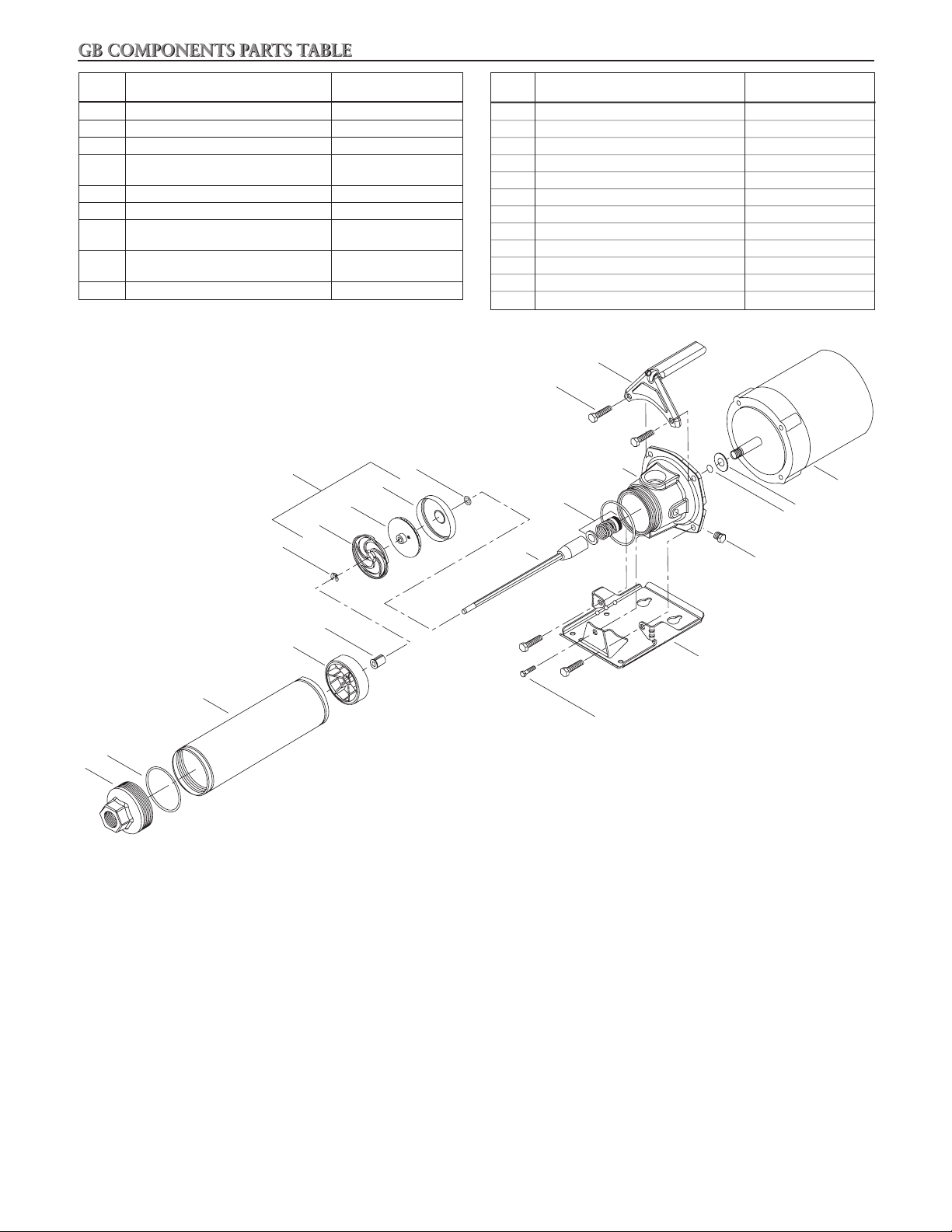
GB COMPONENTS PARTS TABLE
Item
No.
1 Discharge Head Cast Iron
2 O-ring, Casing BUNA
3 Casing 304SS
Polycarbonate
5 Bearing Urethane
6 Klip Ring 301SS
Polycarbonate
Polycarbonate
9 Bowl 304SS
Description Materials
4 Bearing Spider
7 Diffuser
8 Impeller
Glass Filled
Glass Filled
STAGING
7
6
Glass Filled
9
8
Item
No.
10 Shim 304SS
11 Shaft/Coupling Assembly 304SS
12 Mechanical Seal Varies
13 Motor Adapter Cast Iron
14 Screw, Motor Adapter to Motor Steel
15 Handle – optional Steel
16 Screw, Base to Motor Adapter Steel
17 Base Steel
18 Pipe Plug Steel
19 O-ring, Motor Shaft BUNA
20 Deflector BUNA
21 Motor Motor Shaft 300SS
10
Description Materials
15
14
13
12
11
21
20
19
18
5
4
17
3
16
2
1
6
Page 7

GOULDS WATER TECHNOLOGY LIMITED WARRANTY
This warranty applies to all water systems pumps manufactured by Goulds Water Technology.
Any part or parts found to be defective within the warranty period shall be replaced at no charge to the dealer during the warranty period. The warranty period shall exist for a
period of twelve (12) months from date of installation or eighteen (18) months from date of manufacture, whichever period is shorter.
A dealer who believes that a warranty claim exists must contact the authorized Goulds Water Technology distributor from whom the pump was purchased and furnish complete
details regarding the claim. The distributor is authorized to adjust any warranty claims utilizing the Goulds Water Technology Customer Service Department.
The warranty excludes:
(a) Labor, transportation and related costs incurred by the dealer;
(b) Reinstallation costs of repaired equipment;
(c) Reinstallation costs of replacement equipment;
(d) Consequential damages of any kind; and,
(e) Reimbursement for loss caused by interruption of service.
For purposes of this warranty, the following terms have these definitions:
(1) “Distributor” means any individual, partnership, corporation, association, or other legal relationship that stands between Goulds Water Technology and the dealer in
purchases, consignments or contracts for sale of the subject pumps.
(2) “Dealer” means any individual, partnership, corporation, association, or other legal relationship which engages in the business of selling or leasing pumps to customers.
(3) “Customer” means any entity who buys or leases the subject pumps from a dealer. The “customer” may mean an individual, partnership, corporation, limited liability
company, association or other legal entity which may engage in any type of business.
THIS WARRANTY EXTENDS TO THE DEALER ONLY.
Xylem, Inc.
2881 East Bayard Street Ext., Suite A
Seneca Falls, NY 13148
Phone: (800) 453-6777
Fax: (888) 322-5877
www.xyleminc.com/brands/gouldswatertechnology
Goulds is a registered trademark of Goulds Pumps, Inc. and is used under license.
© 2012 Xylem Inc. IM055 Revision Number 3 July 2012
7
Page 8
MANUAL DE INSTRUCCIÓN
IM055
Modelo GB
INSTRUCCIONES DE INSTALACIÓN, FUNCIONAMIENTO Y MANTENIMIENTO
8
Page 9

TEMA PÁGINA
Instrucciones de Seguridad ......................................................................................................................................... 10
Datos de Ingeniería .................................................................................................................................................... 10
Tubería ....................................................................................................................................................................... 10
Cableado y Puesta a Tierra ......................................................................................................................................... 10
Rotación ..................................................................................................................................................................... 11
Operación .................................................................................................................................................................. 11
Mantenimiento ........................................................................................................................................................... 11
Desmontaje ................................................................................................................................................................ 11
Reensamblaje .............................................................................................................................................................. 12
Identificación y Resolución de Problemas ................................................................................................................... 12
Componentes de las bombas LB ................................................................................................................................. 13
Garantía Limitada ...................................................................................................................................................... 14
Declaración de Conformidad ...................................................................................................................................... 21
Número de modelo de la bomba:
Número de serie de la bomba:
Representante:
Número telefónico del representante:
Fecha de compra:
Fecha de Instalación:
Lecturas actuales de la puesta en servicio:
1 Ø 3 Ø L1-2 L2-3 L3-1
Amps: Amps:
Voltios: Voltios:
9
Page 10

INSTRUCCIONES DE SEGURIDAD
ADVERTENCIA
Un voltaje peligroso puede
producir golpes eléctricos,
quemaduras o la muerte.
ADVERTENCIA
PARA EVITAR LESIONES PERSONALES GRAVES O
FATALES, Y DAÑOS SIGNIFICATIVOS A LA PROPIEDAD, LEA Y SIGA TODAS LAS INSTRUCCIONES
DE SEGURIDAD QUE SE ENCUENTRAN EN ESTE
MANUAL O EN LA BOMBA.
ESTE MANUAL TIENE LA FUNCIÓN DE ASISTIRLO
EN LA INSTALACIÓN Y OPERACIÓN DE ESTA UNIDAD Y DEBE CONSERVARSE CON LA BOMBA.
Éste es un SÍMBOLO DE ALERTA DE
SEGURIDAD. Cuando vea este símbolo
sobre la bomba o en el manual, localice
una de las siguientes palabras de señalización y esté alerta ante posibles lesiones personales o daños a la propiedad.
PELIGRO
ADVERTENCIA
PRECAUCIÓN
AVISO: INDICA QUE EXISTEN INSTRUCCIONES
EXAMINE COMPLETAMENTE TODAS LAS INSTRUCCIONES Y ADVERTENCIAS ANTES DE REALIZAR CUALQUIER TRABAJO EN ESTA BOMBA.
CONSERVE TODAS LAS CALCOMANÍAS.
Advierte sobre los peligros que PROVOCARÁN lesiones graves, muerte o daños
significativos a la propiedad.
Advierte sobre los peligros que
PUEDEN PROVOCAR lesiones graves,
muerte o daños significativos a la propiedad.
Advierte sobre los peligros que PRO-
VOCARÁN o PUEDEN PROVOCAR
lesiones o daños a la propiedad.
ESPECIALES MUY IMPORTANTES QUE
DEBEN RESPETARSE.
ESTA UNIDAD NO SE ENCUENTRA
DISEÑADA PARA SER USADA CON
LÍQUIDOS O GASES INFLAMABLES.
ESTOS FLUIDOS PUEDEN ESTAR
PRESENTES EN ÁREAS CONTAMINADAS.
• Carga hasta 600 pies (260 psi)
• Rotación: Hacia la derecha, es decir, en el sentido de
las agujas del reloj cuando se observa desde el extremo
del motor.
TUBERÍA
• La tubería no debe ser menor que las conexiones de
descarga o succión de la bomba. Se debe mantener tan
corta como sea posible, evitando el uso de conexiones
innecesarias para minimizar las pérdidas por fricción.
• Toda la tubería DEBE estar soportada en forma in-
dependiente y NO DEBE existir ninguna carga de la
tubería sobre la bomba.
• Todas las juntas DEBEN ser herméticas. Utilizar 3 ó 4
vueltas de cinta de Teflon™ para sellar las conexiones
roscadas.
CABLEADO Y PUESTA A TIERRA
Instalar el cableado y la puesta
a tierra de acuerdo a los requisitos locales y al Código Eléctrico
Nacional.
Instalar un interruptor de desconexión de todos los circuitos cerca
de la bomba.
Desconectar y bloquear el suministro eléctrico antes de instalar
la bomba o realizar tareas de
mantenimiento.
El suministro eléctrico DEBE ser el que se especifica en la placa nominal de la bomba. Un voltaje
incorrecto puede provocar un incendio y/o dañar el
motor y anular la garantía.
DESCRIPCIÓN Y ESPECIFICACIONES
Las bombas de la Serie GB son bombas portátiles horizontales de etapas múltiples diseñadas para lavados residenciales y agrícolas, aplicaciones de rociado y servicios
de refuerzo en general.
La versión en acero inoxidable 304 se utiliza en la industria de la calefacción y el acondicionamiento de aire, de
filtración y ósmosis inversa y en aplicaciones comerciales
en general.
DATOS DE INGENIERÍA
• Temperatura máxima del líquido: 160°F (72°C)
• Presión máxima de succión: 75 psi
• Las conexiones para la tubería son NPT de 1 pulgada
• Capacidad hasta 33 GPM
10
en la succión y la descarga. Se encuentran disponibles
adaptadores para mangueras de ¾ de pulgada.
Los motores sin protección DEBEN equiparse
con contactores y protectores contra sobrecargas
térmicas si son monofásicos, o con arrancadores
con calentadores si son trifásicos. Consulte la placa
nominal del motor.
• Use únicamente cable trenzado de cobre para la conexión al motor y a tierra. El cable a tierra DEBE ser
por lo menos del mismo tamaño que el cable al motor.
Los cables deben estar codificados con colores para
facilitar el mantenimiento.
Las bombas en aplicaciones de rociado
abierto deben enchufarse en una fuente
de suministro eléctrico protegida por un interruptor de
servicio por falla a tierra. De no hacerlo, podrían ocasionarse lesiones personales graves o fatales y daños materiales.
• Siga cuidadosamente el diagrama de cableado indicado
por el fabricante del motor en la placa nominal o en la
tapa de la terminal.
Page 11
SI LA BOMBA, EL MOTOR Y LOS
Tensión
p
eligrosa
ADVERTENCIA
PRECAUCIÓN
Tensión
p
eligrosa
ADVERTENCIA
Tensión
p
eligrosa
ADVERTENCIA
CONTROLES NO SE CONECTAN A
TIERRA EN FORMA PERMANENTE
ANTES DE CONECTAR LA ALIMENTACIÓN ELÉCTRICA, SE PUEDEN
PRODUCIR SACUDIDAS ELÉCTRICAS, QUEMADURAS Y HASTA LA
MUERTE.
ROTACIÓN
AVISO: LA ROTACIÓN INCORRECTA PUEDE DA-
ÑAR LA BOMBA Y ANULA LA GARANTÍA.
• La rotación correcta es hacia la derecha, en el SENTIDO DE LAS AGUJAS DEL RELOJ cuando se mira
desde el extremo del motor.
Utilizando este método para seleccionar las toberas es
posible mantener una presión positiva en la admisión
de la bomba. Esto evitará que la bomba “robe” agua de
otros grifos.
USO EN GRANJAS LECHERAS
Recomendamos que todas las pistolas WaterGuns® que se
utilizan en granjas que producen leche grado “A” se equipen con un igualador de presión instalado de acuerdo a
las instrucciones que acompañan a este dispositivo. Esto
evitará la presión subatmosférica en la línea de suministro
aún cuando el suministro de agua disminuya. Sugerimos
colgar la pistola WaterGun de la pared, a por lo menos
18 pulgadas del suelo, y contar con un soporte para
mangueras de forma de poder guardar la manguera de
descarga sin que esté en contacto con el piso.
• Para invertir la rotación de un motor trifásico, intercambie dos conductores eléctricos cualesquiera.
OPERACIÓN
SI SE SALPICA O SUMERGE EN
FLUIDOS UN MOTOR ABIERTO A
PRUEBA DE FILTRACIONES PUEDE
OCURRIR UN CORTOCIRCUITO Y
PROVOCARSE UN INCENDIO, SACUDIDAS ELÉCTRICAS, QUEMADURAS,
O INCLUSO LA MUERTE.
AVISO: LA BOMBA DEBE ESTAR TOTALMENTE
CERRADA ANTES DE INICIAR LA OPERACIÓN. NO OPERAR LA BOMBA EN SECO.
• Luego de estabilizar el sistema en las condiciones
normales de operación, controlar la tubería. Si fuera
necesario, ajustar los soportes de la tubería.
No operar la bomba en seco, se dañará el
sello mecánico. No operar contra una
tobera cerrada por períodos de tiempo prolongados pues
se dañarán la bomba y la tubería.
ENSAMBLE DE LA MANIJA
Retirar los dos pernos superiores del adaptador del motor. Insertarlos a través de la parte posterior de la manija
en el adaptador del motor y ajustarlos seguramente.
MANTENIMIENTO
SI NO SE DESCONECTA Y BLOQUEA
EL SUMINISTRO ELÉCTRICO ANTES
DE INTENTAR TAREAS DE MANTENIMIENTO, SE PUEDEN PRODUCIR
SACUDIDAS ELÉCTRICAS, QUEMADURAS O INCLUSO LA MUERTE.
• Los motores tienen cojinetes lubricados en forma
permanente. No es posible, ni necesario, lubricarlos.
Siga las recomendaciones del fabricante para el mantenimiento.
• Para RETIRAR la bomba de servicio, desagote todo el
líquido bombeado de la bomba y la tubería.
• Para VOLVER A PONER la bomba en servicio,
reemplace todos los tapones y tubería utilizando cinta
de Teflon™ o equivalente en las roscas macho.
• Consulte la sección “OPERACIÓN” de este manual.
DESMONTAJE
• Coloque las llaves para tuercas en el adaptador (13)
y el cabezal de descarga (1) y destornille el cabezal de
descarga y la cubierta.
NOTA: LA CARCASA TIENE ROSCA IZQUIERDA EN
AMBOS EXTREMOS Y ESTÁ SELLADA CON
ANILLOS EN O (2).
TOBERAS
Es importante seleccionar la tobera apropiada para el
correcto desempeño de la bomba. Se debe examinar el
grifo que sirve de agua a la bomba para determinar la
velocidad del flujo que proveerá. Si el flujo de un minuto
con el grifo abierto es:
7 galones — Usar la tobera V2005 de 6 gpm
(que se incluye con cada AM2)
6 galones — Usar la tobera V1502 de 5 gpm
5 galones — Usar la tobera SN0045 de 4 gpm
4 galones — Usar la tobera V10152 de 3 gpm
AM
7 Kit
• Retire el anillo de sujeción (6) del extremo del eje (11).
Ahora puede retirar las etapas, consistentes cada una en
un recipiente (9), un impulsor (8) y un difusor (7). Si
la bomba se ha atascado con materia extraña pero no
presenta otros daños, tal vez no sea necesario proseguir
con el desmontaje. Si fuera necesario reemplazar el
conjunto del eje (11), el sello del eje (12) o el motor,
prosiga de acuerdo a las siguientes indicaciones:
• Retire el tapón (18) de la parte posterior del motor y sostenga el eje del motor con un destornillador. Destornille el conjunto del acoplamiento del
eje de la bomba (11) del eje del motor. Retire los
cuatro pernos de montaje del motor (14) y separe
11
Page 12

el motor del marco retirándolo directamente hacia
ADVERTENCIA
Un voltaje peligroso puede
producir golpes eléctricos,
quemaduras o la muerte.
atrás.
• Puede ser necesario palanquear el motor con dos
destornilladores si el sello del eje se pega. El asiento estacionario del sello del eje puede empujarse
fuera del adaptador desde el lado del motor. Hay
un anillo en O de goma en el acoplamiento (19),
entre el eje del motor y el acoplamiento, que generalmente permanece en el eje del motor mientras
el sello se jala por encima de él.
IDENTIFICACIÓN Y RESOLUCIÓN
DE PROBLEMAS
SI NO SE DESCONECTA Y BLOQUEA
EL SUMINISTRO ELÉCTRICO ANTES
DE INTENTAR TAREAS DE MANTENIMIENTO, SE PUEDEN PRODUCIR
SACUDIDAS ELÉCTRICAS, QUEMADURAS O INCLUSO LA MUERTE.
REENSAMBLAJE
Verifique que el deflector de goma (20) y el anillo en O
del acoplamiento (19) estén sobre el eje del motor. Si
están gastados o dañados, reemplácelos. Instale el asiento
del sello estacionario en el bastidor (13) y monte el bastidor (13) y la manija (15) en el motor. Instale el elemento
rotativo del sello, asegurándose de que las caras estén
limpias y que el último miembro de goma pase sobre el
anillo en O del acoplamiento hasta el eje del motor. Enrosque el conjunto del eje de la bomba y el acoplamiento
(11) hasta que se asiente sobre el eje del motor. Con una
regla atravesada sobre la cara del bastidor, verifique la
ubicación del extremo exterior del acoplamiento. Debido
a variaciones en la longitud del eje del motor, etc., el extremo se encontrará entre 0,030 pulgadas corto o a nivel.
Agregue cuñas 7K155 de 0,010 pulgadas hasta que estén
a nivel o sobresalgan, es decir, hasta que la última cuña
interfiera con la regla. Coloque las etapas requeridas,
controlando cada etapa con la regla atravesada sobre el
recipiente y verificando la ubicación del cubo del impulsor para determinar si es necesario agregar cuñas. Una
vez que todas las etapas estén sobre el eje, reemplace el
anillo de sujeción (6).
Inspeccione el anillo en O en el bastidor y el cabezal de
descarga y reemplácelos si estuvieran dañados. Instale
la carcasa (3) y la cruceta del cojinete (4). Enrosque el
cabezal de descarga (1) (atención: roscas hacia la izquierda) y ajuste.
Con un destornillador en el extremo ranurado del eje de
la bomba, dé vuelta la unidad (en el sentido de las agujas
del reloj) antes de reemplazar el tapón (18). Debe girar
sin ninguna otra resistencia que la del sello del eje.
SÍNTOMA
EL MOTOR NO FUNCIONA
Lea las causas N° 1 a 5 en la lista de causas probables
SE ENTREGA POCO O NADA DE LÍQUIDO
Lea las causas N° 6 a 12 en la lista de causas probables
CONSUMO EXCESIVO DE ELECTRICIDAD
Lea las causas N° 3, 12, 13 y 14 en la lista de causas
probables
RUIDO O VIBRACIÓN EXCESIVOS
Lea las causas N° 3, 6, 7, 10, 13, 15 y 16 en la lista de
causas probables
CAUSAS PROBABLES
1. Se disparó el protector térmico del motor
2. Interruptor de circuito abierto o fusible quemado
3. Agarrotamiento del impulsor
4. El cableado del motor es incorrecto
5. El motor es defectuoso
6. La bomba no está cebada, hay aire o gases en el agua
bombeada.
7. Descarga o succión bloqueadas o válvula cerrada
8. Rotación incorrecta (motor trifásico solamente)
9. Baja tensión o pérdida de fase
10. Impulsor gastado o taponado con residuos
11. Carga del sistema muy alta
12. Diámetro incorrecto del impulsor
13. Carga de descarga muy baja — velocidad excesiva de
flujo
14. Viscosidad y/o gravedad específica del fluido muy
altas
15. Cojinete gastado
16. Bomba, motor o tubería flojos
12
Page 13

COMPONENTES DE LAS BOMBAS GB
Ítem
No.
1 Cabezal de descarga Hierro fundido
2 Anillo en O, carcasa BUNA
3 Carcasa Acero inox. 304
relleno de vidrio
5 Cojinete Uretano
6 Anillo de retención Acero inox. 301
relleno de vidrio
relleno de vidrio
9 Recipiente Acero inox. 304
Descripción Materiales
4 Cruceta del cojinete
7 Difusor
8 Impulsor
Policarbonato
Policarbonato
ETAPAS
6
Policarbonato
8
7
Ítem
No.
10 Cuña Acero inox. 304
11 Ensamble eje/acoplamiento Acero inox. 304
12 Sello mecánico Varía
13 Adaptador del motor Hierro fundido
14 Tornillo, adaptador del motor al motor Acero
15 Manija – optativa Acero
16 Tornillo, base al adaptador del motor Acero
17 Base Acero
18 Tapón de tubería Acero
19 Anillo en O, eje del motor BUNA
20 Deflector BUNA
Acero inox. 300
10
9
Descripción Materiales
21 Motor
Eje del motor
15
14
13
12
11
5
4
3
2
1
17
16
19
18
21
20
13
Page 14

GARANTÍA LIMITADA DE GOULDS WATER TECHNOLOGY
Esta garantía es aplicable a todas las bombas para sistemas de agua fabricadas por Goulds Water Technology.
Toda parte o partes que resulten defectuosas dentro del período de garantía serán reemplazadas sin cargo para el comerciante durante dicho período de garantía. Tal período de
garantía se extiende por doce (12) meses a partir de la fecha de instalación, o dieciocho (18) meses a partir de la fecha de fabricación, cualquiera se cumpla primero.
Todo comerciante que considere que existe lugar a un reclamo de garantía deberá ponerse en contacto con el distribuidor autorizado de Goulds Water Technology del
cual adquiriera la bomba, y ofrecer información detallada con respecto al reclamo. El distribuidor está autorizado a liquidar todos los reclamos por garantía a través del
Departamento de Servicios a Clientes de Goulds Water Technology.
La presente garantía excluye:
(a) La mano de obra, el transporte y los costos relacionados en los que incurra el comerciante;
(b) los costos de reinstalación del equipo reparado;
(c) los costos de reinstalación del equipo reemplazado;
(d) daños emergentes de cualquier naturaleza; y
(e) el reembolso de cualquier pérdida causada por la interrupción del servicio.
A los fines de esta garantía, los términos “Distribuidor”, “Comerciante” y “Cliente” se definen como sigue:
(1) “Distribuidor” es aquel individuo, sociedad, corporación, asociación u otra entidad jurídica que opera entre Goulds Water Technology y el comerciante para la compra,
consignación o contratos de venta de las bombas en cuestión.
(2) “Comerciante” es todo individuo, sociedad, corporación, asociación u otra entidad jurídica que realiza negocios de venta o alquiler-venta (leasing) de bombas a clientes.
(3) “Cliente” es toda entidad que compra o que adquiere bajo la modalidad de leasing las bombas en cuestión de un comerciante. El término “cliente” puede significar un
individuo, una sociedad, una corporación, una sociedad de responsabilidad limitada, una asociación o cualquier otra entidad jurídica con actividades en cualquier tipo de
negocios.
LA PRESENTE GARANTÍA SE EXTIENDE AL COMERCIANTE ÚNICAMENTE
Xylem, Inc.
2881 East Bayard Street Ext., Suite A
Seneca Falls, NY 13148
Teléfono: (800) 453-6777
Fax: (888) 322-5877
www.xyleminc.com/brands/gouldswatertechnology
Goulds es una marca registrada de Goulds Pumps, Inc. y se utiliza bajo licencia.
© 2012 Xylem Inc. IM055 Revisión Número 3 Julio 2012
Page 15

MANUEL D'UTILISATION
IM055
Modèle GB
DIRECTIVES D’INSTALLATION, D’UTILISATION ET D’ENTRETIEN
Page 16
SUJET PAGE
Consignes de Sécurité ................................................................................................................................................. 17
Données Techniques ................................................................................................................................................... 17
Tuyauterie .................................................................................................................................................................. 17
Câblage et Mise à la Terre .......................................................................................................................................... 17
Rotation ..................................................................................................................................................................... 18
Utilisation ................................................................................................................................................................... 18
Entretien .................................................................................................................................................................... 18
Démontage ................................................................................................................................................................. 18
Remontage ................................................................................................................................................................. 19
Diagnostic des Anomalies ........................................................................................................................................... 19
Table de Composants du Modèle GB .......................................................................................................................... 20
Déclaration de Conformité ......................................................................................................................................... 21
Garantie Limitée......................................................................................................................................................... 24
Informations pour le propriétaire
Numéro de modèle de la pompe :
Numéro de série de la pompe :
Détaillant :
Nº de téléphone du détaillant :
Date d’achat :
Date d’installation :
Courant mesuré au démarrage :
1 Ø 3 Ø L1-2 L2-3 L3-1
A : A :
V : V :
16
Page 17
CONSIGNES DE SÉCURITÉ
DANGER
AVERTISSEMENT
AVERTISSEMENT
Les fluides dangereux
peuvent causer un
incendie, des brûlures
ou la mort.
AVERTISSEMENT
Les tensions dangereuses
peuvent causer un choc
électrique, des brûlures
ou la mort.
AVERTISSEMENT
Tension
dangereuse
AVERTISSEMENT
AFIN DE PRÉVENIR LES BLESSURES GRAVES OU
MORTELLES ET LES DOMMAGES MATÉRIELS
IMPORTANTS, LIRE ET SUIVRE TOUTES LES
CONSIGNES DE SÉCURITÉ FIGURANT DANS LE
MANUEL ET SUR LA POMPE.
LE PRÉSENT MANUEL A POUR BUT DE FACILITER
L’INSTALLATION ET L’UTILISATION DE LA POMPE ET DOIT RESTER PRÈS DE CELLE-CI.
Le symbole ci-contre est un SYMBOLE
DE SÉCURITÉ employé pour signaler
les mots-indicateurs dont on trouvera la
description ci-dessous. Sa présence sert à
attirer l’attention afin d’éviter les blessures
et les dommages matériels.
Prévient des risques qui VONT causer
des blessures graves, la mort ou des
dommages matériels importants.
Prévient des risques qui PEUVENT
causer des blessures graves, la mort ou
des dommages matériels importants.
ATTENTION
AVIS : SERT À ÉNONCER LES DIRECTIVES
SPÉCIALES DE GRANDE IMPORTANCE
QUE L’ON DOIT SUIVRE.
LIRE SOIGNEUSEMENT CHAQUE DIRECTIVE ET
AVERTISSEMENT AVANT D’EFFECTUER TOUT
TRAVAIL SUR LA POMPE.
N’ENLEVER AUCUN AUTOCOLLANT DE SÉCURITÉ.
Prévient des risques qui PEUVENT causer
des blessures ou des dommages matériels.
APPAREIL NON CONÇU POUR LES
LIQUIDES DANGEREUX NI POUR
LES GAZ INFLAMMABLES. CES
FLUIDES POURRAIENT ÊTRE PRÉSENTS DANS LES INSTALLATIONS
DE CONFINEMENT (PUITS COLLECTEURS).
TUYAUTERIE
• An de réduire les pertes de charge au minimum, on
devrait maintenir la tuyauterie aussi courte que possible, ne pas employer un calibre de tuyau inférieur
à celui des raccords d’aspiration et de refoulement
ni utiliser d’accessoires ou de raccords de tuyauterie
superflus.
• Tous les tuyaux DOIVENT posséder leurs propres
supports et N’appliquer AUCUNE contrainte sur la
pompe.
• Chaque joint DOIT être étanche. Enrouler les raccords
filetés de 3 ou 4 couches de ruban de téflonMC pour les
étancher.
CÂBLAGE ET MISE À LA TERRE
Poser le fil de terre et les autres
fils suivant les prescriptions du
code provincial ou national de
l’électricité.
Poser un sectionneur tout conducteur près de la pompe.
Verrouiller la source d’alimentation électrique en position ouverte
avant de procéder à l’installation
ou à l’entretien de la pompe.
L’alimentation électrique DOIT être conforme aux
spécifications de la plaque signalétique. Une tension inappropriée peut causer un incendie ou des
dommages au moteur et annule la garantie.
Les moteurs monophasés non protégés DOIVENT
être munis de contacteurs et de dispositifs de
protection contre les surcharges thermiques, et les
moteurs triphasés, de démarreurs à dispositif de
protection contre la surcharge. Consulter la plaque
signalétique du moteur.
DESCRIPTION et CARACTÉRISTIQUES
La pompe de la série GB est une pompe multi-étagée,
horizontale, portative, conçue pour l’augmentation de
pression générale, la nébulisation et le lavage au jet à des
fins domestiques et agricoles.
Sa version en inox 304 est utilisée pour les systèmes commerciaux ordinaires, de CVCA (chauffage, ventilation et
conditionnement d’air), de séparation par osmose inverse
et de filtrage.
DONNÉES TECHNIQUES
• Température maximale du liquide : 72 °C (160 °F).
• Pression d’aspiration maximale : 75 lb/po2.
• Raccords d’aspiration et de refoulement : 1 po NPT ;
• Débit de refoulement maximal : 33 gal US/min.
• Hauteur de charge maximale : 600 pi (à 260 lb/po2).
• Rotation : sens horaire (vers la droite, vu de l’extrémité
adaptateurs pour tuyaux flexibles de ¾ po offerts.
du moteur).
• N’utiliser que du l torsadé en cuivre pour la mise
à la terre et l’alimentation du moteur. Le calibre du
fil de terre DOIT être au moins égal à celui des fils
d’alimentation, et les fils devraient tous être chromocodés pour faciliter l’entretien.
On doit brancher les pompes servant à
la nébulisation ou au lavage au jet sur
une prise munie d’un disjoncteur de fuite à la terre pour
prévenir les blessures graves ou mortelles ainsi que les
dommages matériels.
• Suivre soigneusement le schéma de câblage sur la
plaque signalétique ou le cache-bornes du moteur.
OMETTRE LA MISE À LA TERRE PERMANENTE DE LA POMPE, DU MOTEUR OU DES COMMANDES AVANT
LE BRANCHEMENT À LA SOURCE
DE COURANT PEUT CAUSER UNE
COMMOTION ÉLECTRIQUE, DES
BRÛLURES OU LA MORT.
17
Page 18
ROTATION
AVERTISSEMENT
Tension
dangereuse
ATTENTION
AVERTISSEMENT
Tension
dangereuse
AVIS : LA ROTATION DANS LE MAUVAIS SENS
PEUT ENDOMMAGER LA POMPE ET ANNULE LA GARANTIE.
• La rotation appropriée est en sens HORAIRE (vers la
droite), vue de l’extrémité du moteur.
• Pour inverser la rotation des moteurs triphasés, en
intervertir deux des conducteurs.
UTILISATION
USAGE AGRICOLE JOURNALIER
Il est recommandé que tous les appareils WaterGunMD
utilisés sur les fermes produisant du lait de catégorie A
soient munis d’un casse-vide installé conformément aux
directives fournies avec le casse-vide. On évitera ainsi
la création d’une pression négative dans les conduites
d’alimentation, même si l’alimentation en eau diminuait. Il est suggéré d’accrocher le WaterGun au mur, à au
moins 18 po du plancher, et d’employer un support pour
ranger le tuyau de refoulement flexible de manière à que
le tuyau ne touche pas au plancher.
ARROSER UN MOTEUR ABRITÉ OU
LE PLONGER DANS UN LIQUIDE
PEUT CAUSER UN COURT-CIRCUIT,
UNE COMMOTION ÉLECTRIQUE,
DES BRÛLURES OU LA MORT.
AVIS : ON DOIT REMPLIR LA POMPE ENTIÈRE-
MENT POUR L’AMORCER AVANT DE
L’UTILISER. NE PAS FAIRE FONCTIONNER
LA POMPE À SEC.
• Faire fonctionner la pompe dans des conditions de
service normales, attendre que le système se stabilise,
vérifier la tuyauterie et régler les supports de celle-ci au
besoin.
Ne pas utiliser la pompe à sec pour ne pas
endommager la garniture (joint) mécanique. Ne pas la faire tourner longtemps lorsque l’ajutage
(sortie) est fermé, car cela endommagera la pompe et la
tuyauterie.
POSE DE LA POIGNÉE
Enlever les deux vis de fixation supérieures de
l’adaptateur de moteur, placer les deux trous de boulon
de la poignée en face de ceux de l’adaptateur, reposer les
vis et les serrer à fond.
ENTRETIEN
OMETTRE LE VERROUILLAGE DE
LA SOURCE D’ALIMENTATION
ÉLECTRIQUE EN POSITION OUVERTE PEUT CAUSER UNE COMMOTION ÉLECTRIQUE, DES BRÛLURES
OU LA MORT.
• Les moteurs sont dotés de roulements à billes lubriés
à vie. Aucune lubrification n’est donc nécessaire ni
possible. Suivre les recommandations du fabricant du
moteur.
• Pour mettre une pompe HORS service, vidanger la
pompe et tous les tuyaux.
• Pour remettre une pompe EN service, reposer tous les
bouchons de vidange après avoir recouvert les filets
extérieurs de ruban de téflonMC ou l’équivalent.
• Voir la section « UTILISATION » ci-dessus.
DÉMONTAGE
• À l’aide de deux clés – l’une sur l’adaptateur (13) et
l’autre sur la tête de refoulement (1) –, dévisser cette
dernière et le corps de pompe (3).
AJUTAGE
Il importe de choisir l’ajutage approprié pour optimiser
les performances de la pompe. On devrait vérifier le débit
du robinet d’alimentation de la pompe. Si le débit en gal
US/min est :
De 7, employer un ajutage V2005 (6 gal US/min),
inclus avec les AM2.
De 6, utiliser un ajutage V1502
(5 gal US/min).
De 5, utiliser un ajutage SN0045
(4 gal US/min).
Nécessaire
AM 7
De 4, employer un ajutage V10152
(3 gal US/min).
Cette méthode de sélection des ajutages permet de
maintenir une pression positive à l’entrée de la pompe et
d’empêcher cette dernière de « couper » l’alimentation en
eau des autres sorties (robinets).
18
NOTA : LE CORPS DE POMPE EST FILETÉ À
GAUCHE À CHAQUE EXTRÉMITÉ, ET
SON ÉTANCHÉITÉ EST ASSURÉE PAR DES
JOINTS TORIQUES (2).
• Enlever l’agrafe de retenue (6) de l’extrémité de l’arbre
(11). On peut maintenant démonter chaque étage, formé d’un corps d’étage (9), d’une roue (8) et d’un diffuseur (7). Si la pompe est engorgée sans pour autant
être endommagée, un démontage plus poussé peut être
inutile. Si l’on doit remplacer l’arbre (11), la garniture
mécanique (12) ou le moteur, procéder comme suit :
• Enlever le bouchon (18) situé à l’arrière du moteur et
bloquer l’arbre de moteur avec un tournevis. Dévisser l’ensemble accouplement-arbre de pompe (11).
Enlever les quatre vis de fixation (14) de l’adaptateur
de moteur. Séparer le moteur de l’adaptateur en le
tirant en ligne droite.
• Si la garniture mécanique est grippée sur l’arbre, on
peut employer deux tournevis en guise de leviers
pour retirer le moteur. On peut pousser l’élément
Page 19

fixe de la garniture hors de l’adaptateur en se plaçant
AVERTISSEMENT
Les tensions dangereuses
peuvent causer un choc
électrique, des brûlures
ou la mort.
du côté moteur. Un joint torique en caoutchouc est
monté entre l’arbre de moteur et l’accouplement et
reste habituellement sur l’arbre lorsque la garniture
est retirée.
REMONTAGE
Vérifier si le déflecteur (20) en caoutchouc et le joint
torique (19) de l’accouplement sont montés sur l’arbre
de moteur. S’ils sont usés ou endommagés, les remplacer.
Poser l’élément fixe de la garniture mécanique dans
l’adaptateur (13), puis fixer l’adaptateur et la poignée
(15) au moteur. Mettre l’élément mobile de la garniture
en place tout en s’assurant que ses surfaces sont propres
et que son dernier élément en caoutchouc glisse par-dessus le joint torique de l’accouplement, puis sur l’arbre de
moteur. Visser l’ensemble accouplement-arbre de pompe
(11) à fond sur l’arbre de moteur. Avec une règle rectifiée placée en travers des bords de l’adaptateur, vérifier
la position de l’extrémité extérieure de l’accouplement.
En raison de variations dans la longueur de l’arbre de
moteur, notamment, l’extrémité peut affleurer ou être
jusqu’à 0,030 po trop à l’intérieur. En pareil cas, poser
des cales 7K155 de 0,010 po contre l’extrémité extérieure de l’accouplement jusqu’à ce qu’elles affleurent ou
dépassent la règle (la dernière cale touche alors la règle).
Remettre les étages requis en place tout en vérifiant, avec
une règle rectifiée placée en travers des bords de chaque
corps d’étage (cuvette), si le moyeu de roue de chaque
étage est bien placé ou s’il est nécessaire d’ajouter des
cales. Une fois les étages correctement en place, reposer
l’agrafe de retenue (6).
Vérifier le joint torique du corps de pompe et celui de la
tête de refoulement et les remplacer s’ils sont endommagés. Poser le corps de pompe (3) et la bague d’espacement
(4) du coussinet. Visser la tête de refoulement en place
(filetage à gauche) et à fond.
Avec un tournevis inséré par l’orifice du bouchon (18)
dans la fente située à l’extrémité de l’arbre de pompe,
faire tourner l’arbre dans le sens horaire : il devrait
tourner sans autre résistance que celle de la garniture
mécanique de l’arbre. Remettre le bouchon en place.
DIAGNOSTIC DES ANOMALIES
OMETTRE LE VERROUILLAGE DE
LA SOURCE D’ALIMENTATION
ÉLECTRIQUE EN POSITION OUVERTE PEUT CAUSER UNE COMMOTION ÉLECTRIQUE, DES BRÛLURES
OU LA MORT.
ANOMALIE
NON-FONCTIONNEMENT DU MOTEUR
(V. causes probables 1 à 5)
DÉBIT DE REFOULEMENT FAIBLE OU NUL
(V. causes probables 6 à 12)
CONSOMMATION D’ÉNERGIE EXCESSIVE
(V. causes probables 3, 12, 13 et 14)
VIBRATION ET BRUIT EXCESSIFS
(V. causes probables 3, 6, 7, 10, 13, 15 et 16)
CAUSES PROBABLES
1. Protecteur thermique du moteur déclenché
2. Disjoncteur ouvert ou fusible sauté
3. Roue grippée
4. Moteur mal connecté
5. Moteur défectueux
6. Pompe non amorcée, air ou gaz présent dans le
liquide pompé
7. Tuyau d’aspiration ou de refoulement obstrué ou
robinet fermé
8. Mauvais sens de rotation (moteurs triphasés
seulement)
9. Basse tension électrique ou perte de phase
10. Roue usée ou engorgée
11. Hauteur de charge trop élevée du système
12. Diamètre de roue inapproprié
13. Hauteur de refoulement trop faible - débit excessif
14. Viscosité ou densité trop élevée du liquide
15. Roulements usés
16. Pompe, moteur ou tuyauterie mal assujettis
19
Page 20
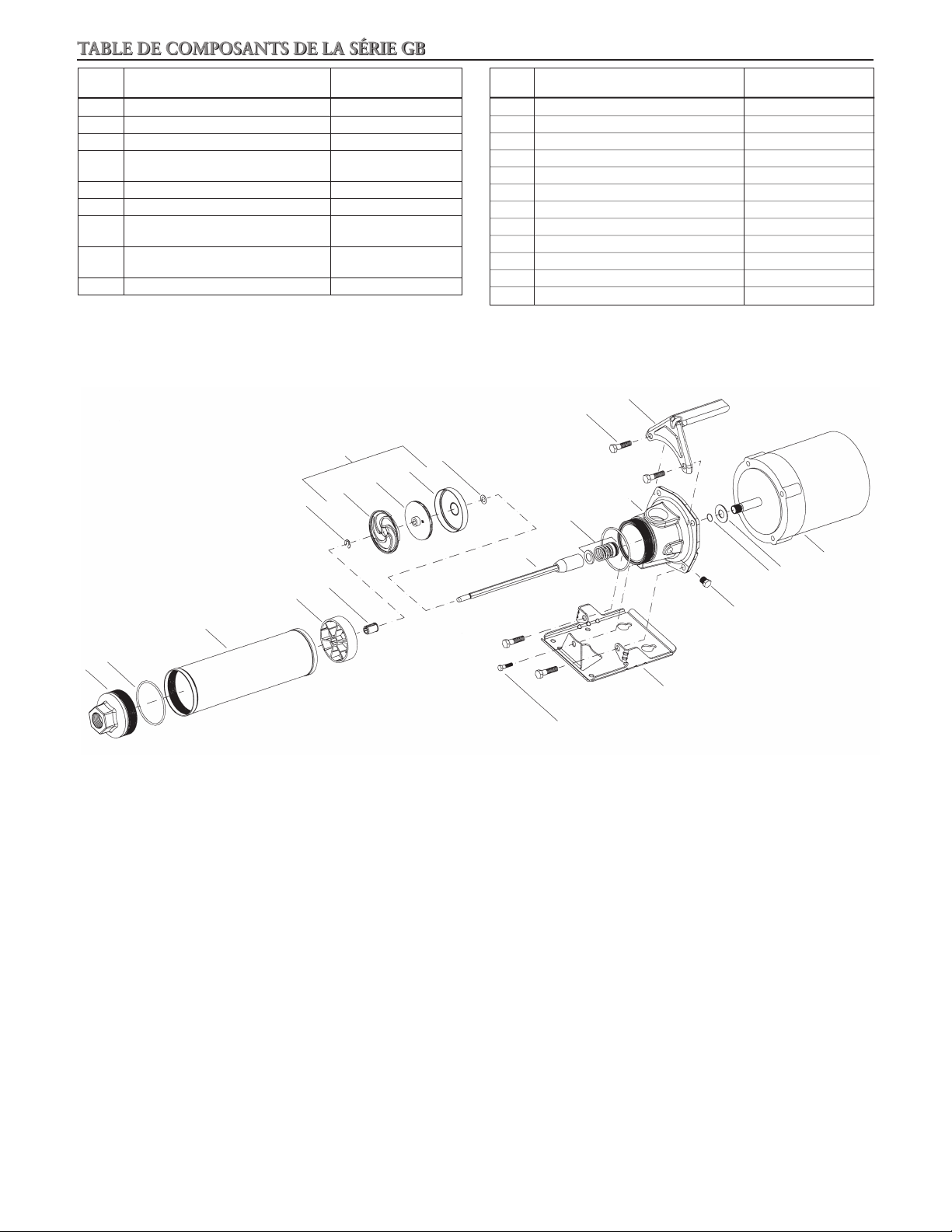
TABLE DE COMPOSANTS DE LA SÉRIE GB
No
d’article
1 Tête de refoulement Fonte
2 Joint torique (corps de pompe) Buna
3 Corps de pompe Inox 304
de fibre de verre
5 Coussinet Uréthane
6 Agrafe de retenue Inox 301
de fibre de verre
de fibre de verre
9 Corps d’étage (cuvette) Inox 304
Description Matériaux
4 Bague d’espacement (coussinet)
7 Diffuseur
8 Roue
Polycarbonate chargé
Polycarbonate chargé
Polycarbonate chargé
No
d’article
10 Cale Inox 304
11 Ensemble accouplement-arbre de pompe Inox 304
12 Garniture mécanique Varient
13 Adaptateur de moteur Fonte
14 Vis (adaptateur de moteur, moteur) Acier
15 Poignée (en option) Acier
16 Vis (plaque-support, adaptateur) Acier
17 Plaque-support Acier
18 Bouchon (conduite) Acier
19 Joint torique (arbre de moteur) Buna
20 Déflecteur Buna
21 Moteur Arbre en inox 300
Description Matériaux
14
ÉTAGE
8
7
6
5
4
3
2
1
10
9
12
11
16
15
13
21
20
19
18
17
20
Page 21

Declaration of Conformity
Declaration of Conformity
We at,
Goulds Water Technology/Xylem Inc.
1 Goulds Drive
Auburn, NY 13021
Declare that the following products: NPE, MCS, MCC, 3656, 3656 SP, GB, e-SV, SVI, NPO, Prime Line
SP, HB, HMS, LC, NPV, LB, LBS comply with Machine Directive 06/42/EC. This equipment is intended
to be incorporated with machinery covered by this directive, but must not be put into service until the
machinery into which it is to be incorporated has been declared in conformity with the actual provisions
of the directive.
Declaración de Conformidad
Declaración de Conformidad
Nosotros en
Goulds Water Technology/Xylem Inc.
1 Goulds Drive
Auburn, NY 13021
Declaramos que los siguientes productos: NPE, MCS, MCC, 3656, 3656 SP, GB, e-SV, SVI, NPO, Prime
Line SP, HB, HMS, LC, NPV, LB, LBS cumplen con las Directivas para Maquinarias 06/42/EC. Este
equipo ha sido diseñado para ser incorporado a la maquinaria cubierta por esta directiva pero no debe
ponerse en funcionamiento hasta que se declare que la maquinaria en la que será incorporado cumple
con las disposiciones reales de la directiva.
Déclaration de Conformité
Déclaration de Conformité
Nous, à
Goulds Water Technology/Xylem Inc.
1 Goulds Drive
Auburn, NY, U.S.A. 13021,
déclarons que les produits NPE, MCS, MCC, 3656, 3656 SP, GB, e-SV, SVI, NPO, Prime Line SP, HB,
HMS, LC, NPV, LB et LBS sont conformes à la directive 06/42/EC (législation relative aux machines). Ils
sont destinés à être intégrés dans la machinerie faisant l’objet de ladite directive, mais ne doivent pas être
mis en service tant que la machinerie en question ne sera pas déclarée conforme aux stipulations de la
directive.
21
Page 22

NOTES/NOTAS
22
Page 23

NOTES/NOTAS
23
Page 24

GARANTIE LIMITÉE DE GOULDS WATER TECHNOLOGY
La présente garantie s’applique à chaque pompe de système d’alimentation en eau fabriquée par Goulds Water Technology.
Toute pièce se révélant défectueuse durant la période de garantie sera remplacée sans frais pour le détaillant durant ladite période, qui dure douze (12) mois à compter de la
date d’installation ou dix-huit (18) mois à partir de la date de fabrication, soit la période qui expirera la première.
Le détaillant qui, aux termes de cette garantie, désire effectuer une demande de règlement doit s’adresser au distributeur Goulds Water Technology agréé chez lequel la pompe
a été achetée et fournir tous les détails à l’appui de sa demande. Le distributeur est autorisé à régler toute demande par le biais du service à la clientèle de Goulds Water
Technology.
La garantie ne couvre pas :
a) les frais de main-d’oeuvre ou de transport ni les frais connexes encourus par le détaillant ;
b) les frais de réinstallation de l’équipement réparé ;
c) les frais de réinstallation de l’équipement de remplacement ;
d) les dommages indirects de quelque nature que ce soit ;
e) ni les pertes découlant de la panne.
Aux fins de la présente garantie, les termes ci-dessous sont définis comme suit :
1) «Distributeur» signifie une personne, une société de personnes, une société de capitaux, une association ou autre entité juridique servant d’intermédiaire entre Goulds
Water Technology et le détaillant pour les achats, les consignations ou les contrats de vente des pompes en question.
2) «Détaillant» veut dire une personne, une société de personnes, une société de capitaux, une association ou autre entité juridique dont les activités commerciales sont la
vente ou la location de pompes à des clients.
3) «Client» signifie une entité qui achète ou loue les pompes en question chez un détaillant. Un «client» peut être une personne, une société de personnes, une société de
capitaux, une société à responsabilité limitée, une association ou autre entité juridique se livrant à quelque activité que ce soit.
CETTE GARANTIE SE RAPPORTE AU DÉTAILLANT SEULEMENT.
Xylem, Inc.
2881 East Bayard Street Ext., Suite A
Seneca Falls, NY 13148
Téléphone: (800) 453-6777
Télécopie: (888) 322-5877
www.xyleminc.com/brands/gouldswatertechnology
Goulds est une marque déposée de Goulds Pumps, Inc. et est utilisé sous le permis.
© 2012, Xylem Inc. IM055 Révision numéro 3 Juillet 2012
 Loading...