

Page 1

Global Water
800-876-1172 • globalw.com
02-056
Publication Number 38580512
Global Water
Instrumentation, Inc.
151 Graham Road
P.O. Box 9010
College Station, TX 77842-9010
T: 800-876-1172
Int’l: (979) 690-5560, F: (979) 690-0440
E-mail : globalw@globalw.com
FC220 Flow Monitor
- 1 -
Page 2

Global Water
800-876-1172 • globalw.com
Congratulations on your purchase of the Global Water FC220 Flow
Monitor. This instrument has been quality tested and approved for
providing accurate and reliable measurements. We are confident that you
will find the monitor to be a valuable asset for your applicati on. Should you
require assistance, our technical staff will be happy to help.
Table of Contents
I. FC220 Flow Monitor Description • • • Page 3
II. FC220 Specifications • • • • 5
III. Flow Calculation Modes • • • • • 6
IV. Switch Settings • • • • • 8
V. Sensor Input • • • • • 9
VI. 4-20mA Output • • • • • 9
VII. Relay Operation • • • • • • 9
VIII. Power Saving Mode • • • • • 10
IX. Scientific Notation • • • • • 10
X. Totalizer • • • • • • 10
XI. Programming Setup Parameters • • • • 11
XII. Data Logger Option • • • • • 17
XIII. Maintenance and Troubleshooting • • • 18
XIV. Appendix A: Terminal Strip Diagram • • • 21
XV. Appendix B: Flume and Weir Equation Parameters • 22
* Copyright Global Water Instrumentatio n, Inc. 2012
- 2 -
Page 3

Global Water
800-876-1172 • globalw.com
I. FC220 Flow Monitor Description
The Global Water FC220 F low Monitor is a reliable and accurate instrument for
measuring and totalizing water flow in a wide variety of applications. Wate r level is
measured using Global W ater’s popular WL400 level sensor, WL700 ultrasonic
sensor, or almost any other 4-20mA, 0-5V or 0-1V water level sens or. Flow is then
calculated by the microprocessor using a variety of different techniques. The backlit
LCD display shows real-time flow, water level or total flow in user selectable units;
and the 8-button keypad easily guides the user thr ough the versa tile setup menus.
The FC220 supports several different types of flow calc ulation modes. Over 40
preprogrammed flume and weir equations are included. For monitoring in round pipes
and open rectangular channels; the Manning’s Equation mode allows the user to enter
their own parameters for material type, slope and pipe or chann el dimensions.
Standard flow equations c an also be defined; which c an calculate flow for almost all
flumes and w eirs. Another mode lets the user enter parameters for a b est fit 3
polynomial that is usefu l for calculating flow based on empirical data and lookup
tables. In addition, a factory programmable lookup table can be permanently stored in
the processor s m em ory for monitoring i n applications where a single equation can’t
accurately predict flo w, such as strea mbeds and open channels with complicated
geometry . A 16-character name can be programmed in to the FC220 by the user to
identify the ins tal la ti on si te or show other information about the configuration.
Water flow i s displayed w ith up to 7 digits which allows for the display of flow i n the
largest app lications. The totalizer records flow volume up to 9 digits with floating
point and sc ientific (engineering) notation supported in non-volatile memory, and is
password protected from reset. The maximum recordable total vol ume is more tha n
one trillion cubic feet. Available volume units are cubic feet, gallons, milli on gallons,
cubic meter s and liters; time units incl ude seconds, minutes, hou rs and days. T his
allows for the display of flow in 20 different user de fined units. Water level is
calibrated and displayed in feet, inc hes, meters or centimeters; and a level of fset
function allows the mea sured level to be adjusted to compensate f or variation s in
sensor installation. The engineering u nits for all display modes and setup parameters
are independently programmable, which allows f or the greate st possible versatility.
rd
order
- 3 -
Page 4

Global Water
800-876-1172 • globalw.com
Four indepe ndent relay outputs are provided for triggering external devices like water
samplers and monitoring devices. These relays can be separately programmed to
trigger bas ed on volume per pulse, and threshold se ttings can be used to limit
triggering to flows above preset levels. There is also an acc urate and scalable 4-20mA
output provided for monitoring flow using data loggers and PL C devices. An internal
USB data logger is available as a factory option tha t allows the historical flow data to
be recorde d, as well as the exact time of each relay trigger event. Free software is
provided for programming the data lo gger, downloading flow and relay data, and
exporting to spreadsheets. Programmable power sa ving features allow the supply
current to be reduced, which is import ant in remote monitoring ap plic a ti ons.
A 16 characte r by 2 line LCD display can s how either the current flow ra te, the water
level, or the volume in the totalizer. The 8-button keypad allows the selection of the
display modes, and the pr ogramming of the setup para meters. The DISPLAY button
toggles the LCD display between the flow rate, the water level, and the totalizer. This
button also allows the quick exit from the setup menus when in any setup mode.
Holding the MENU button down for two seconds enters the setup menu. In setup
mode, the MENU button moves from one menu selection to another. The BACK
button moves the user backward through the vario us setup options. The SAVE bu tton
will save a se tup param eter to memory. The UP, DOWN, LEFT and RIGHT arrow
buttons are used to select a nd change setup parameters.
Note:
The FC220 fl ow monitor re quires a level sensor to ope rate. Two and three wire level
sensors with 4-20mA, 0-5 volt and 0-1 volt outputs are sup ported. A sen sor is not
supplied with the FC220, contact Global Water for more information on available
sensors.
- 4 -
Page 5

Global Water
800-876-1172 • globalw.com
II. FC220 Specif ications:
Power Requirements: 12VDC or 18-24VDC Input, +/-10%
Supply Current: 13mA + Sensor Current + Backlight + 4-20mA Output
150mA M aximum Total Cur rent
Backlight C urrent: 23mA when on
Internal Fuse: 315mA
Power Adap tor: 18VDC Universal Power Supply, 90-220VAC Input
Equation Fo rmats: Manning’s Equation for Round Pipes
Manning’s Equation for Rectangular Channels
Standard Flow Equation : Q=A*(B+Ch)^ D
3
rd
Order Polynomial: Q=A+Bh+Ch^2+Dh^3
Stored Flumes: H Type: 0.5, 0.75, 1.0, 1.5, 2.0
HS Type: 0.4, 0.6
Parshall : 1”, 2”, 3”, 6” , 9”, 12”, 24”, 36”, 48”, 60”, 72”
Palmer-Bowlus: 4”, 6”, 8”, 10”, 12”, 15”, 18”, 24”, 30”, 36”
Trapezoi da l: 60º
Stored Weirs: Rectangular: 1’, 2’ 3,
V-Notch: 22.5º, 30º, 45º, 60º, 90º, 120º
Cipollet ti: 1’, 1.5’, 2’, 3’, 4’
Lookup Table: One, Factory Programmable Only
Output Relays: 4 Independent SPDT Relays, Pulse On Time = 1 Second
Contact Rating: 8A @ 250VAC, 5A @ 30VDC Resistive
Level Sensor Input: 2-Wire or 3-wire, 4-20mA, 0-5VDC, 0-1VDC
Output: 4-20mA Scalable
Display/Keypad: 16 Character x 2 Line Backlit LCD, 8-Button Tactile Keypad
Flow Capacity: 7 Digit Maximum, Auto-Floating point
Totalizer Capacity: 9 Digit Maximum
Auto-Floating Point, Engineering notation su ppor ted
Max Volume = 1.0995E12 Cubic Feet (1.0995 x 10^ 12 Ft³)
Level Capacity: 5 Digit Maximum
Display Resolution: 3 Decimal Pla ces Maximum, Auto-Adjusting
Accuracy: Sensor Accuracy + Equation/Table Error + 0.1% + 1 Digit
Level Units: Feet, Inches, Meters, Centimeters
Volume Units: Cubic Feet, Gallons, Million Gallons, Cubic Meters, Liters
Time Units: Seconds, Minutes, hours, Days
Flow Units: 20 Combinations of Volume and Time Units Above
Dimensions: 7.1”W x 5.1”H x 1.4D (180mm x 130mm x 35mm)
Weight: 1 lb
- 5 -
Page 6

Global Water
800-876-1172 • globalw.com
III. Flow Calculation Modes
The FC220 de termines flow from water level in several different ways. Standard flow
equations, Manning’s Equation, polynomials or a lookup table can all be used. The
following equation formats calculate flow in cubic feet per second based on the
measured wa ter level in feet. A conversion is made by the microprocessor so that the
display and 4-20mA output work in the user defined flow units.
Flow Equation:
There are standard flow equati on parameters for over 40 flumes and weirs stored in the
FC220. The user also has the ability to enter their ow n parameters for the flow
equation in the form of:
Q = A * (B+Ch)^D
Where:
Q = Flow in Cubic Feet Per Second
A - D = User Programmable C oefficients. If B is not used, enter zero
h = Water Level in Feet
If this mode is selected, the user is prompted to enter the four param eter s in the
equation, A, B, C and D.
Manning’s Equation:
The Manning’s Equation is a widely accepted way of ca lculating the flow in any
gravity feed partially full channel of known geometry. Two applications are
supported, round pipes and rectangular channels. T he equation is in the form of :
Q = ( 1.486 / n ) * WA * ( WA / WP ) ^ 0.6667 * ( Slope ) ^ 0.5
Where:
Q = Flow in cubic feet per second
n = Roughness Factor
WA = Wetted Area in Feet², cross sectional area of the w ater at any given depth
WP = Wetted Pe rimeter in ft, length of bottom and side s tha t is we t at any given de pt h
Slope = Slope of channel or pipe, drop in elevation divided by length of drop.
- 6 -
Page 7

Global Water
800-876-1172 • globalw.com
In these modes the user is either prom pted to enter the pipe diameter or rectangular
channel width, in use r programmable units. The WA and WP are automatically
calculated ba se d on the diameter or width, and the measured water level.
The roughness factor is determined by the construction material, typical values are:
0.010 Plastic, othe r smooth surf aces
0.012 Smooth unpainted steel
0.013 Painted steel, coated cas t iron
0.013 Clay drainage tile, sm ooth asphalt
0.013 Finished conc rete
0.014 Vitrified clay sewer tile
0.014 Uncoated cast iron
0.017 Unfinished concrete
0.024 Corrugated metal storm drain
Polynomial:
A best fit 3
rd
order poly nomial can also be used to calculate flow. This is useful when
you need to find an equatio n that best fits measured data or a lookup table. The
equation is in the for m of:
Q = A + Bh + Ch² + Dh³
Where:
Q = Flow in cubic feet per second
A - D = User defined coefficients
h = Water level in feet
When selec ting this mode, the user is prompted to enter the values for A, B, C and D.
Look-Up Table:
For applications where a single equation does no t properly calculate flow, a single
look-up table can be programmed into the FC220. This is a factory programmable
option only. Data for this table must be provided to G lobal Water in two columns and
no more than 200 lines. The firs t column is water level in fee t and the second column
is the flow in cubic feet per second at that water level. Liner interpolation is
automatically done when a measured water level is between two data points.
- 7 -
Page 8

Global Water
800-876-1172 • globalw.com
IV. Switch Settings
Inside the FC220 is a bank of 8 switches which are used to select the s ensor type and
power input. Select the switches as follows:
Select only one of SW1 and SW2, leave the other swi tch off
SW1: ON, Sensor power is 12 volts
SW2: ON, Sensor power is 18-24 volts depending on the voltage input to the
FC220. Note this feature is not available when running from a 12 volt batte ry
SW3: ON, Sensor power is continuous
SW3: OFF, S ensor power is switched on and off by the microprocess or in power
saving mode. If not using power saving mode, set SW3 to ON.
SW4: ON, Sensor type is 4-20mA
SW4: OFF, S ensor type is 0-5 VDC or 0-1 VDC
SW5: ON, Sensor type is 4-20m A or 0-5 VDC
SW5: OFF, S ensor type is 0-1 VDC
SW6: This switch is unused
Select only one of SW7 and SW8, leave the other switch off
SW7: ON, Power input to the FC220 is 18-24 VDC
SW8: ON, Power input to the FC220 is 12 VDC
- 8 -
Page 9

Global Water
800-876-1172 • globalw.com
V. Sensor Input
The FC220 acc epts any water level sensor with a 4-20mA, 0-5VDC or 0-1VDC output.
Available power for the sensor depends on the power input to the F C220. When
powering the FC2 2 0 from 12 volts, the sensor p ow er is also 12 volts. I f you are
running from a power supply of 18-24 volt s, the sensor power can be se lected from
either a regulat ed 12 vo lt s upply, or directly from the 18-24 volt input. The power can
also be conne cted continuously or it can be set to be tur ned on and off by the FC220
when using powe r saving mode . In this mode the sensor is turned on at user defined
intervals f or a programmable warm-up time, then turned off again to conserve powe r.
VI. 4-20mA Output
A 4-20mA output is prov ide d tha t is pro p ort i ona l to wa ter fl ow . This allow s the water
flow history to be recorded by an external data logger or PLC, or by the internal data
logger opti on, or both. The output is scalable and allows the user to se lect the flow
rates that ar e proportional to the 4mA and 20mA output currents.
VII. Relay Operation
Four indepe ndently prog rammable relays are provided for triggering extern al devices.
These outputs are generally intended for triggering water sam plers when doing flow
proportion al sampling, or f or recording by an external data logger or PLC. The relays
are single pole double throw (SPDT) types with common, normally open and normally
closed conta cts available at the terminal block inside the FC220. The setup menu
allows the user to independently set the volume of water per output pulse, and set a
threshold level that inhibits the acc umulation of volume when the flow is below a user
defined flow rate. The relays are pulsed on for 1 second when the volume of water
since the last pulse equals the volume per pulse setting, and the flow rate is a bove the
threshold level. Example: The volume per pulse is se t to 100 gallons and the
threshold setting is 10 gallons per minute. As long a s the flow rate is 10 gallons per
minute (GPM) or more, the water volume is counted and one pulse will occur for
every 10 gallons. If the flow f alls below 10 GPM the counting of water volume will
stop until the flow rises above the thre shold setting again. If the flow is above 10
GPM long enough to accumulate 5 gallons, then falls below 10GPM, counting stops
but the accumulated 5 gallons is r etained. W hen the flow rate rises above 10GPM
again, only 5 more gallon s is needed to output a relay pulse.
- 9 -
Page 10

Global Water
800-876-1172 • globalw.com
VIII. Power Saving Mode
A power saving mode is provided that allows the operating current to be reduced in
remote monitoring applic ations. One wa y this is accomplished is to turn off the LCD
display backlight, this saves about 20mA of current. Three modes allow the user to
turn the backlight on all the time, off all the time, or turn it on for one minute only. In
this last mode, the backlight will come on for one minute when any of the b uttons on
the keypad are pressed, then turn off again. The wate r level sensor can also be turned
on and off periodically to r educe power consumption. The user can program a sample
rate of 0-60 minutes, and can se t the sensor warm-up time of 0-60 seconds. Example:
The sample rate is 30 minutes and the warm-up time is 3 seconds. The sensor will be
turned on for 3 seconds every 30 minutes then shut off again. Durin g the time the
sensor is off the flow display and 4-20mA output will in di cat e a flow ba se d on t he las t
level reading. The totalizer will continue to be incre mented, and the relays will
continue to oper a te, based on that last reading. A fter 30 minut es more, a new reading
will be taken and the di spla y and 4-20mA output updated aga in. Note that using the
4-20mA output will increase the current draw by a n amount equal to the output
current.
IX. Scientific Notation
Scientific no tat i on is generally used for displaying very large or very small numbers.
It represen ts a number as being multiplied by 10 raised to a power, such as 5.67* 10^2
being equal to 567 since 10^2 equals 100 (10^2 = 10²). Engineering notation is similar
but only uses 10 raised to a power that is a multiple of 3; like 10^3 (one t ho us an d),
10^6 (one million) or 10^9 (one billion) . This notatio n also replaces “*10^” with “E”
(Exponent) so that 5.67E2 is eq uivalent to 5.67*10^2 or 567. The notation E2 is also
equivalent to “shift the decimal point to the right two times”. This makes the di splay
of large numbers easier to read; 5.67E 3 is 5.67 thousand or 5670, 5.67E6 is 5.67
million, et c. In the same way, small numbers less that one can be shown as 10 raised
to a negative power, or “shift the decimal point that many time s to the lef t” ; suc h as
5.67E-3 = 0.0 0567 or 5.67 thousandths, 5.67E-6 = .0000 0567 or 5.67 millionths.
X. Totalizer
A 9-digit totalizer keeps track of the total volume of water that has ac cumulated since
the last time the totaliz er was reset. The totalizer display supports engineering notation
and can store volumes up to 1.1E 1 2 cub ic fe et ( 1. 1 x 10^ 12 or 1. 1 tril li o n) in any of the
- 10 -
Page 11

Global Water
800-876-1172 • globalw.com
5 selectable volume uni ts. The engine ering notation is automa tically switched on
when the totalizer volume exceeds the capacity of the 9-digit display.
The totalizer re se t funct i on is pa ssword protected, pre ve nt in g a user from entering the
reset menu. This menu also allows the user to change the password. The password is
4 digits in the range of 0000-9999. When s hipped from the factory the def ault
password is 123 4. It is recom mended that the password be changed bef ore ins tal l in g
the FC220. If the password is lost or forgotten, contact the Technical Support
department at Global Water.
XI. Programming Se tup Paramet ers
Press the MENU button for 2 second s to enter the s etup menu. Pressing the MENU
button again cycles through the differ ent setup options. Pressi ng the BACK button
moves backw ard to the previous display. Pressing the DISPLAY button from any
menu exits to the norma l display mode. Press the RIGHT arrow button to enter any of
the setup sub-m enus. These su b-menus are Set Leve l Unit, Set Volume Unit, Set Time
Unit, Calibrate Sensor, 4-20mA Output Calibration, Set Site Info, Power Saving, Relay
Settings, and Totalize r Reset. Note that while in the setup menus, flow calc ulations
and relay opera ti ons w ill s to p. A fter one minute of inactivity, the FC220 will
automatically return to the main dis play and operation mode.
The followi ng three menus set the level, volume and time units used for sh ow i ng da t a
on the main display. The level unit is used to display the water level. The volume
unit is used to display the totalizer, the total volume of flow since last reset. The
volume and time units are combined to form the flow units of Volume/Time. Other
setup parameters in these menus have independently programmable units. Cha ng i ng a
unit of measure in one me nu will not affect the settings in any other menu.
Set Level Unit:
This unit is used to display water leve l on the main display. The current se tt ing is
shown in the Set Level Units menu. Use the RIGHT arrow to change the level units.
Use UP and DOWN to select either Feet, Inches, Meter s or Centimeters. Press Save to
store the new setti n g.
- 11 -
Page 12

Global Water
800-876-1172 • globalw.com
Set Volume Unit:
This unit is used to d isplay the to talizer volume on the main display. The current
setting is shown in the Set Volume Unit menu. Use the RIGHT arrow to change the
volume units. Use Up and D OWN to select either Cubic Feet, Gallons, Million
Gallons, C ubic Meters, or L iters. Press SAVE to store.
Set Time Unit:
This unit, combined with the volume unit from the previous menu, is used to determine
the flow unit on the main d isplay. The c urrent time units are shown in the Set Tim e
Unit menu. Use the RIGHT arrow to change the time units. Use U p and DOWN to
select either Seconds, M inutes, Hours or Days. Press SAVE to store.
Example: If the volum e unit is set to cubic feet and th e time unit is se t to seconds, the
flow unit is autom atic a lly cub ic fe et per sec ond. There are 20 possible combinations
of volume a nd time units that determine the flow unit.
Calibrate Sensor:
To change or check the sensor calibra tion press the RIGHT arrow button. To skip the
calibration option press the MENU ke y to move to the next option or press BACK to
return to norm al disp l ay mode.
The low water level is set a t zero. Remove the level se nsor from the water and pres s
SAVE to store the raw data num be r for t he zero le vel sensor output. I n the case of an
ultrasonic sensor, place it at a distance from a target equivalent to the zero water level
point. Press MENU to move forward to the High Level option. Place the sensor at a
known depth as close to maximum range of the sensor as possible. Use the LEFT and
RIGHT arrows to select a digi t to modify, then use the UP and DOWN arr ows to scroll
through digits 0-9 and decimal point. Select just one decimal point if it is needed. In
this manner change the High Level numbers to match the depth of the sensor. Use the
- 12 -
Page 13

Global Water
800-876-1172 • globalw.com
RIGHT arrow to move to the level unit, the units will flash. Use UP and DOWN to
select the unit that corresponds to th e high level that was just set. Press SAVE to store
these setting s. Press MENU to move forward. Press the SAV E button to store the raw
data value for the high level sensor output. Press MENU to move to the level offset
option. The level offset is added to (or subtracted from) the measured water level to
correct for e rrors in installation. For example, if a sensor is installed horiz ontally in
the bottom of a pipe you can a dd the radius of the sensor housing to m ake up for the
fact that the sensor out put will not change until the water level reaches the center. The
radius of the WL400 sensor is 0.41” and the radius of the FL400 sensor is 0.50”. Use
the arrows to set the leve l offset. Set the first character to either + or – to add or
subtract the offset respectively, select the remaining characters f rom 0-9 and decimal
point. Press SAVE to store the offset value.
4-20mA Output Calibration:
To scale and calib rate the 4-20mA output press the RIGHT arrow key. The 4mA Set
Point is the amount of flow that results in an output current of 4mA, generally zero.
Use the arrow buttons to change the setting. Use the RIGHT arrow to advance to the
volume unit until it flashes. Use UP and DOWN to select the volume unit. Use the
RIGHT arrow to advance to the time unit. Use UP and DOWN to select the time unit .
Press SAVE to store these settings and MENU to move forward. The 20mA Set Point
is the magnitude of flow that c auses a 20mA output current. Use the arrow buttons to
change the s et point valu e, the units are those selected in the previous me nu. Press
SAVE to store this setting. Any flow betwee n the se tw o set po i nts wi ll be scal ed to t he
corresponding output cur rent. The next three me nus are generally set at the factory
and should not need to be changed. The 4mA Output Cal menu allows the 4-20mA
output to be set to exactly 4mA. Connect a DC current meter between the 4-20mA
output and grou nd. Use the UP and DOWN arrows to raise and lower the r aw data
number (and output current) until the current meter reads exactly 4.000mA. Press
SAVE and MENU. The 20mA Output Cal menu sets the 20mA output in the same
way. Use UP and DOWN to adjust the output until the current meter read s exactly
20.000mA. The Calibrate Logger menu is used to recalibrate the FC220 data lo gger
option only and will be discussed in the section titled Data Logger Option and in the
Data Logger Option softwa re manual.
- 13 -
Page 14
Global Water
800-876-1172 • globalw.com
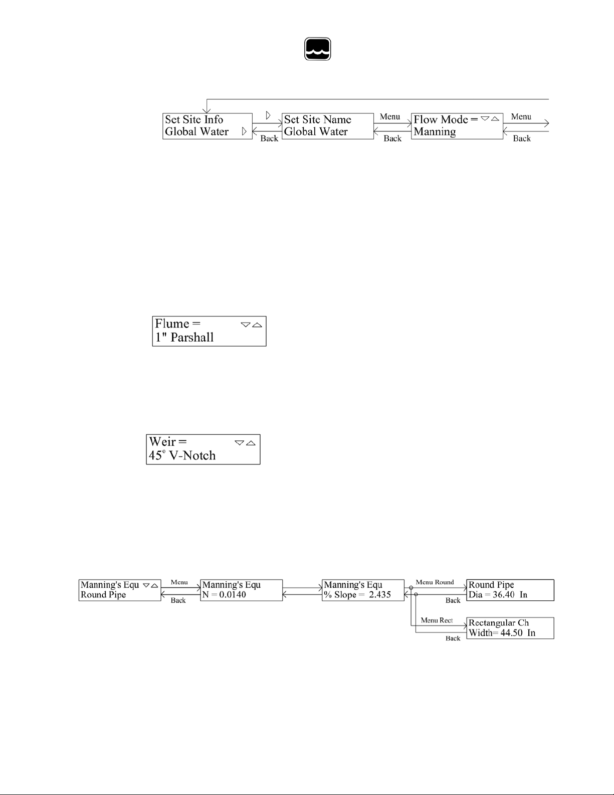
Set Site Info:
The Site Info menu is where the type of fl ow monitor ca lculation is defined. A 16
character site name or label can also be added for reference. The current site name is
shown in the Set Site Info menu. T o change site information press the RIGHT arrow
button. Change the site name in the first sub-menu. Use the LEFT and RIGHT arrows
to select a charac ter and th en scroll throug h available characters usin g UP and DOWN.
Press SAVE to store and MENU to move forward. The next menu sets the ty pe of
flow calculation; use UP and DOWN to choose one of: flume, weir, Manning’s
Equation (round pipe or rectangular channel), standa rd flow equation, best fit 3
rd
order
polynomial, or look-up table. Press SAV E to store the f low mode.
Flume:
If Flume is selected, the user is prompte d to select a flume type from a list of standard
flumes. See the specifications secti on for a list of available flumes. The flow equation
parameters a re shown in Appendix C. Use UP and DOWN to select the flume type
and press SAVE to store the change.
Weir:
If Weir is selected, the user is prompted to select a weir type from a list of standard
weirs. See the specifications section for a list of available weirs. The flow equation
parameters a re shown in Appendix C. Use UP and DOWN to select the we ir type and
press SAVE to store the change.
Manning’s Equation:
Use UP and DOWN to select either Round Pipe or
Rectangular Channel. Pr ess SAVE to store and MENU to
advance. To set the roughness ind ex n, use LEFT and RIGHT to select a digit and UP
and DOWN to change it. Press SAVE and MENU. In the same manner, enter the
slope in percent. Press SAVE and MENU. Enter the diameter of the round pipe or the
- 14 -
Page 15

Global Water
800-876-1172 • globalw.com
width of the rectangular channel. Use the RIGHT arrow to advance to the units until
they flash, use UP and DOWN to select the unit and press SAVE to store the settings.
Standard Flow Equation:
The water flow through most or all flumes and weirs can be described by the equation
shown above. Use the MENU, arrow buttons and SAVE to set the parameters A - D.
Not all flow equations req uire all 4 coefficients. If B is not used enter 0.000, if C is
not used enter 1.000 as shown above. A and D can also be set to 1.000.
rd
3
Order Polynomial:
A set of data points such as from a lookup table can be approximated by a polynomial.
The 3
rd
order polynomial show n above can give a very good approximation of flow in
many cases. The accuracy of the equat ion will vary depending on the accuracy and
number of the data point s. Errors can i ncrease toward the uppe r and low e r end s of the
curve. If the normal range of flow is kno wn, the equati on coefficients can be adjusted
to minimize errors within the measurement range. Near zero flow the approximation
can result in negative numbers. While these negative numbers are generally very
small, they must be ignored for the purposes of displaying flow and updating the
totalizer and 4-20mA output. Any negative number calculated by the p olynomial wi ll
be consider ed zero flow. U sin g the ar row bu tto ns, SAVE and MENU; set the
parameters A – D observing the +/- signs. The expon ent is one digit in the range of -9
to +9.
Look-Up Table:
A single lookup table can be selected i n cases where an application can’t be modeled
by an single equation. The lookup table and table name are factory programmable
only. A name of up to 16-characters, and lookup ta ble da ta must be supplied. For
more information contact the Technical Support department at Global Water.
- 15 -
Page 16

Global Water
800-876-1172 • globalw.com
Power Saving Mode:
The power sa ving mode allows the average power consumption to be reduced by
controllin g the time when the water level sensor and LCD backlight are turned on. To
set the power saving parameters, press the RIGHT arrow button. The LCD Backlight
has 3 settings, ON turns the backlight on all the time, OFF forces the backlight to be
off, and 1 Minute mode will turn the backlight on when any butt on on the keypad is
pressed, then it will turn off again after one minute of inactivity. Use the UP and
DOWN arrows and SAVE to set and save the s etting. The Sample Rate is the interval
between sens or rea d ing s (and how often the display and 4-20mA output will be
updated). Use LEFT and RIG HT to select a digit and use U P and DOWN to scroll
through 0-9, press SAVE to st ore the setti ng. The Sensor Warmup time is how long
the sensor will be powered on before a reading is take n. Set this para meter in the same
manner as the sample rate. In this e xample the backlight is in 1 minute mode. The
sensor will be turned on for 3 seconds every 60 minutes. T he di spla y and 4-20mA
output will remain on but will continue to indicate the flow that corr e spo n ds to the last
level measur ement. During the tim e the sensor is off , the totaliz er and relays will
continue to operate based on the last sensor reading.
Relay Settings:
To modify Relay Settings, press the RIG HT arrow button. Each relay is independe nt
of the others and must be programmed sep arately. Use the UP and DOWN arrows to
select which relay is to be changed, press MENU to move to the next sub-menu. The
Volume of Pulse setting is the am ount flow needed to generate a relay pulse. The relay
number selected is shown at the lower right. If a relay is not used, enter zero and no
pulses will be generate d. Use LEFT and RIGHT to select a digit, and UP and Down to
scroll through the numbers. Use the RIGHT arrow to move to the volume units, select
using UP and DOWN. Press SA VE to store the setting. The Minimum T hreshold
setting inhibits the counting of pulse volume unless the flow rate is above the threshold
level. The selected relay number is shown at the lowe r right. Set the threshold level,
volume unit and time unit in the same w ay , then press SAVE. In the above example,
relay 2 will be pulsed for every 100 cubic feet of water as long as the flow rate is over
10 cubic feet per second. Any water flow while the flow rate is below the 10 cubic
feet per second threshold will not be counted toward the 100 cubic foot pulse volume.
- 16 -
Page 17

Global Water
800-876-1172 • globalw.com
Totalizer Reset:
The Totalize r Reset me nu allows the totalizer to
be reset to ze ro. The rese t is password protected.
This menu also allows the password to be changed. When shipped from the factory
the password is set to 1234. Press the RIGHT arrow to e nter the password. Use the
LEFT and RIGHT arrows to select each digit, and use UP and DOWN to scroll
through the numbers. Pre ss MENU to m ove forward provided that the password was
entered cor rectly. If the password is lost or forgotten, contact t he Global Water
Technical Support department. If you want to reset the totalizer c oun ter to zer o, use
UP or DOWN to select YES, then SAVE. If you do not want to reset the counter,
select NO. Press Menu to move forward. I f you said YES you must confirm the reset,
use UP or DOWN to select yes, then SAVE and MENU. If you want to cha nge the
password, use UP or DOWN to select YES, then SAVE and MENU. Use the LEFT
and RIGHT a rrows to select each digit and use UP and DOWN to scroll through the
numbers. Press SAVE and MENU. Confirm the new password by e ntering it agai n in
the same manner as before.
XII. Data Logger Option
A factory option for the FC220 is an internal data logger which records a historical
record of wa ter flow, and r ecords the exact time of each relay pulse. C ha nne l o ne of
the data logger records f low and channel two records relay events. A special software
package allows the programming of the logger and the download of recorded flow and
relay data. This softwar e differs from other Global Water data logger software in the
way it proce sses the relay data. Softwar e such as Global Logger II will work with the
FC220 data logger option but some rela y information will not be seen. The data logger
is factory calibrated a nd should not need to be recalibrated again. Should you need to
recalibrate the logger, consult the Data Logger Option manual.
- 17 -
Page 18

Global Water
800-876-1172 • globalw.com
XIII. Maintenance and Troubleshooting
a. Global Water recomme nds verifying the sensor’s calibration e very 6
months.
b. The screen on the end of the sensor must be peri odically checked for
clogging from mud, sludge , and other debris. Wash the screen with clean
water and/ or scrub it gently with a toothbrush. Do not insert obj ects
through the screen, as this may cause damage to the sensor.
c. In battery ope rated systems it is recommended that the battery be replaced
every 3-4 years, more often in harsh enviro nments or when the battery is
allowed to be completely discharged.
Trou ble Shootin g
d. Verify that the power source is supplying correct vo lta ge to t he F C2 20
and to the sensor.
e. Make sure that the vent tube ha s not be e n kinked or sealed. The sensor
uses this tube to compensate for barometric pressure changes.
f. Check the sensor’s calibration.
g. Clean the sensor following the maintenance instructions.
Testing the sensor:
To check the level sensor calibration separate from the flow monitor, you
will need:
1 column of water (the closer the depth is to the maximum range of the
sensor the better the cali bration will be)
1 power supply
1 current meter
Connecting wires as necessary
Unplug the Flow Meter and disconnect the sensor. Connect the
sensor to the power supply and current meter in the following way.
Attach the black wire to the positive input of the current meter. Connect
the ground terminal of the power supply to the ground of the current
meter. Attach the red wire to the positive termina l of the power supply.
- 18 -
Page 19

Global Water
800-876-1172 • globalw.com
See Appendix A. Warning: Always connect the sensor with the power
turned off.
At zero feet (out of water ), the se ns or sh ou ld ou t put a ppr o xim a tely
4mA. This can be read directly on the current meter or, if using the
voltmeter method, the meter should read 0.5 volts across a 125 ohm
resistor. At the maximum water depth of t he sensor, the sensor should
output approximately 20mA or 2.50 volts across the 125 ohm resistor.
Issue: Wate r in the vent tube
a. If water gets into the vent tube the water level readings can show very
large errors and can be erratic. If water gets into the vent tube of the cable
place it nex t to a heater for 24 hours to dry the inside of the cable.
Other issues
a. Call Global Water for tec h support: 800-876-1172 or (979) 690-5560
(many problems can be solved over the phone). Fax: (979) 690-0440 or
Email:
globalw@globalw.com
.
When calling for tech support, please have the following information
ready;
1. Model #.
2. Unit serial number .
3. P.O.# the equipment was pur c ha sed o n.
4. Our sales number or the invoice number.
5. Repair instructio ns and/or specific problems relating to the
product.
Be prepared to describe the problem you are experiencing including
specific deta ils of the appl ica ti on, ins tallation, an d any addition al
pertinent inf ormation.
b. In the event that the equipment needs to be retur ned to the factory for any
reason, ple ase call to ob tain an RMA# (Return Material Authori zation).
Do not return items without an RMA# displayed on the outside of the
package.
Clean and decontaminate the FC220 if necessary.
Include a written statement describing the problems.
- 19 -
Page 20

Warranty
a. Global Water Instrumentation, Inc. warrants that its products are free
b. The warr anty begins on the date of your invoice.
Global Water
800-876-1172 • globalw.com
Send the package with shipping prepaid to our factory address. Insur e
your shipment, Global Water’s warranty does not cover damage incurred
during transi t.
from defects in material and workmanship under nor mal use and
service for a period of one year from date of shipm ent from factory.
Global Water’s obligations under this warranty are limited to, at
Global Water ’s option: (I) replacing or (II) repairing; any products
determined to be defective. In no case shall Global Water’s liab ility
exceed the prod uc ts or igi na l pur c has e pr ice . This warra nty does no t
apply to any equipment that has been re paired or altered, except by
Global Water Instrumentation, Inc., or which has been subject to
misuse, negligence or a ccident. It is e xpressly agreed that this
warranty will be in lieu of a ll warranties of fitness and in lieu of the
warranty of merchantability.
- 20 -
Page 21

Global Water
800-876-1172 • globalw.com
XIV. Appendix A: Ter m ina l S tr ip Diagram
POWER IN:
V+ 12VDC or 18-24VDC Input
V+ 12VDC or 18-24VDC Input
12VDC Input: SW7 OFF, SW8 ON
18-24VDC Input: SW7 ON, SW8 OFF
GND Power Supply and System Ground
GND Power Supply and System Ground
SENSOR IN:
V+ Sensor Power
12VDC Sensor Power: SW1 ON, SW2 OFF
18-24VDC Sensor Power: SW1 OFF, SW2 ON
(18VDC Power Input Only)
IN Sensor Input
Sensor Power Cont inuous: SW3 ON
Sensor Power Switched: SW3 OFF (Power Saving Mode)
4-20mA Sensors: SW4 ON, SW5 ON
0-5VDC Sensors: SW4 OFF, SW5 ON
0-1VDC Sensors: SW4 OFF, SW5 OFF
4-20mA:
OUT 4-20mA Output
GND Power Supply and System Ground, 4-20mA return P ath
RELAY 1-4:
- 21 -
Page 22

EQ Type:
1 = Flow
2 = Poly
Q=A*(B+Ch)^D
Q=A+Bh+Ch^2+Dh^3
Flumes
EQ Type A B C D
0.5 H Flume 1 1.600
0.000000
1
2.200
0.75 H Flume
1
1.770
0.000000
1
2.230
1.0 H Flume 1 1.950
0.000000
1
2.300
1.5 H Flume 1 2.120
0.000000
1
2.300
2.0 H Flume 1 2.370
0.000000
1
2.230
1" Parshall 1 0.338
0.000000
1
1.550
2" Parshall 1 0.676
0.000000
1
1.550
3" Parshall 1 0.992
0.000000
1
1.550
6" Parshall 1 2.060
0.000000
1
1.580
9" Parshall 1 3.070
0.000000
1
1.530
12" Parshall 1 3.950
0.000000
1
1.550
24" Parshall 1 8.000
0.000000
1
1.550
36" Parshall
1
12.000
0.000000
1
1.570
48" Parshall
1
16.000
0.000000
1
1.580
60" Parshall
1
20.000
0.000000
1
1.590
72" Parshall
1
24.000
0.000000
1
1.590
4" Palmer-Bowlus
1
1.730
0.005880
1
1.957
6" Palmer-Bowlus
1
2.071
0.005421
1
1.903
8" Palmer-Bowlus
1
2.537
0.014560
1
1.972
10" Palmer-Bowlus
1
2.843
0.016160
1
1.953
12" Palmer-Bowlus
1
3.142
0.017000
1
1.936
15" Palmer-Bowlus
1
3.574
0.016800
1
1.906
18" Palmer-Bowlus
1
3.988
0.018750
1
1.898
24" Palmer-Bowlus
1
4.574
0.040800
1
1.950
30" Palmer-Bowlus
1
5.022
0.062500
1
1.966
36" Palmer-Bowlus
1
5.462
0.080000
1
1.991
60º Trapezoidal
1
1.550
0.000000
1
2.580
0.4HS
2
-3.48332E-05
2.10389E-03
3.51517E-01
4.39885E-01
0.6HS
2
-7.52381E-05
8.29552E-03
4.01877E-01
3.79339E-01
Global Water
800-876-1172 • globalw.com
XV: Appendix B: Flume and Weir Equation Parameters
- 22 -
Page 23

Weirs
EQ Type A B C D
1.0' Rectangular
1
3.333
0.000000
1
1.500
2.0' Rectangular
1
6.667
0.000000
1
1.500
3.0' Rectangular
1
10.000
0.000000
1
1.500
22.5º V-Notch
1
0.505
0.000000
1
2.500
30º V-Notch 1 0.676
0.000000
1
2.500
45º V-Notch 1 1.028
0.000000
1
2.500
60º V-Notch 1 1.420
0.000000
1
2.440
90º V-Notch 1 2.490
0.000000
1
2.475
120º V-Notch
1
4.333
0.000000
1
2.500
0.5' Cipolletti
1
1.684
0.000000
1
1.500
1.0' Cipolletti
1
3.367
0.000000
1
1.500
1.5' Cipolletti
1
5.051
0.000000
1
1.500
2.0' Cipolletti
1
6.374
0.000000
1
1.500
3' Cipolletti 1 10.101
0.000000
1
1.500
4' Cipolletti 1 13.468
0.000000
1
1.500
Global Water
800-876-1172 • globalw.com
- 23 -
 Loading...