

Page 1

Description of the
Communication protocol
for Series 30 and Series40 pressure transmitters from KELLER
Class.Group = 5.20
Version 3.0
MJK Digital Pressure Transmitters 7060 and 7070
Page 2

1 Introduction............................................................................................................................................................................3
2 Bit transfer layer (physical layer) .........................................................................................................................................3
2.1 Introduction ........................................................................................................................................................................... 3
2.2 Characteristic ........................................................................................................................................................................3
2.3 RS485 half-duplex details .....................................................................................................................................................4
3 Data-link layer.........................................................................................................................................................................5
3.1 Transmission format for the serial interface .......................................................................................................................... 5
3.2 Format of a message ............................................................................................................................................................6
3.3 Principle of message interchange ......................................................................................................................................... 7
4 MODBUS communication......................................................................................................................................................9
4.1 MODBUS Communication Basics......................................................................................................................................... 9
4.2 Using MODBUS with KELLER products ............................................................................................................................... 9
The MJK
4.3 Description of MODBUS functions ............................................................................................................................... ....... 10
4.4 Modbus Communication Examples............................................................................................................................... ...... 10
4.5 Function 3: MODBUS Register Read............................................................................................................................... ... 10
4.6 Function 6: MODBUS Single Register Write....................................................................................................................... 11
4.7 Function 8: MODBUS Echo Test ........................................................................................................................................ 11
4.8 Function 16: MODBUS Register WRITE.............................................................................................................................12
4.9 MODBUS Register Map ...................................................................................................................................................... 13
4.10 Device Operation Command List ...................................................................................................................................... 16
5 Description of Keller bus functions ...................................................................................................................................17
5.1 Example: read pressure value with exception handling ...................................................................................................... 17
5.2 Function 30: Read coefficient.............................................................................................................................................. 18
5.3 Function 31: Write coefficient.............................................................................................................................................. 20
5.4 Function 32: Read configuration ......................................................................................................................................... 21
5.5 Function 33: Write configuration ......................................................................................................................................... 21
5.6 Function 48 : Initialise and release............................................................................................................................... ....... 23
5.7 Function 66 : Write and read new device address ............................................................................................................. 24
5.8 Function 69 : Read serial number ............................................................................................................................... ....... 24
5.9 Function 73 : Read value of a channel (floating point)....................................................................................................... 25
5.10 Function 74 : Read value of a channel (integer) ...............................................................................................................26
5.11 Function 95 : Commands for setting the zero point .......................................................................................................... 27
5.12 Function 100 : Read configuration .................................................................................................................................... 28
5.13 Function 101 : Write configuration .................................................................................................................................... 28
6 Appendix...............................................................................................................................................................................30
6.1 Interface converter ..............................................................................................................................................................30
6.2 floating-point format IEEE754 ............................................................................................................................................. 30
6.3 Error handling and recognition ............................................................................................................................................ 31
6.4 Calculation of the CRC16 checksum .................................................................................................................................. 33
6.5 Description of the software driver (DLL).............................................................................................................................. 34
6.6 Changes.............................................................................................................................................................................. 37
6.7 Software versions................................................................................................................................................................ 37
6.8 Support................................................................................................................................................................................ 37
Communication protocol Serie30 Page 2/37
Page 3
1 Introduction
This document describes the communications protocol for the Series 30 digital pressure transmitters from KELLER
MJK
Druckmesstechnik. In addition to these transmitters, other devices such as data loggers or manometers are also offered. These
products are distinguished by the designation CLASS. Within this device class, the individual device groups are differentiated by
the designation GROUP. All Series 30 pressure transmitters bear the CLASS designation 5.
The software version number consists of following components:
short-designator:
Class Group Year Week
Device group SW-Version
Series 30 and 40 5 20 SW-Version: release year SW-Version: release week
In this document, the software version is defined by Class.Group-Year.Week, e.g. 5.20-5.50.
The protocol itself is based on MODBUS, but incorporates optimised functions for the device, these functions are called Keller
bus functions. However, minimum (only fct3) MODBUS RTU functionality is implemented for devices CLASS.GROUP = 5.20
with firmware 2.40 and newer. Full MODBUS support is provided from firmware 5.20-10.XX on.
See Appendix for an overview of differnet versions.
2 Bit transfer layer (physical layer)
2.1 Introduction
The physical connection is provided by the RS485 serial interface. This guarantees good interference immunity and enables a
flexible bus structure, i.e. several devices can be administrated as slaves by a single master. In order to minimise the scope of
cabling, the RS485 is used in half-duplex mode. This means that 2 wires are required for communications and 2 wires for power
infeed.
2.2 Characteristic
In order to operate several devices at one serial interface, they are simply all connected in parallel (RS485A, RS485B, GND and
+Vcc). Before incorporating the devices into the bus, each device must be programmed with a different address.
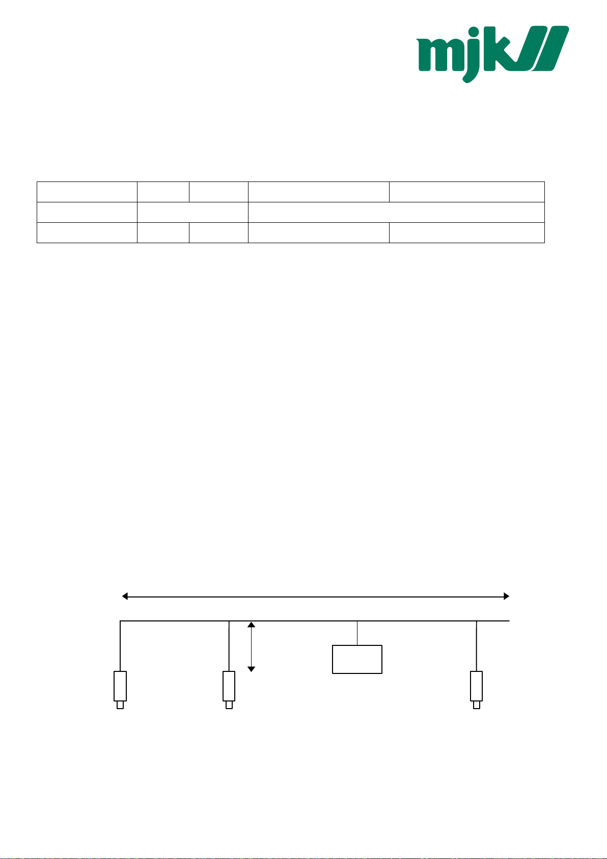
It is possible to configure a network up to a length of 1300 metres with a maximum of 128 devices. Each riser cable may be up to
14 m in length. The employed cable should correspond to specification EIA RS485.
max. 1300m
max. 14m
master
dev. ndev. 2dev. 1
Communication protocol Serie30 Page 3/37
Page 4
4.3 Description of MODBUS functions
This section describes the MODBUS functions supported by Series 30 transmitters (device Class.Group = 5.20)
Overview:
F3: Read registers on MODBUS address space
F6: Write single register on MODBUS address space
F8: MODBUS Echo function
F16: Write multiple registers on MODBUS address space
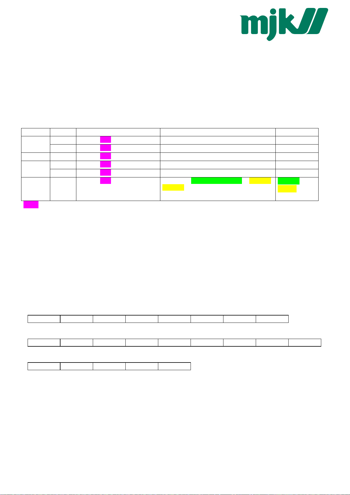
4.4 Modbus Communication Examples
Read P1
Read P2
Read
TOB1
Read P1
and
address
250
1
1
250
1
1
request response
250 3 0 2 0 2 112 64 250 3 4 63 117 228 166 102 72
1 3 0 2 0 2 101 203 1 3 4 63 117 240 123 227 222
1 3 0 4 0 2 133 202 1 3 4 63 118 6 224 21 213
250 3 0 8 0 2 80 66 250 3 4 65 181 99 178 29 163
1 3 0 8 0 2 69 201 1 3 4 65 181 192 121 110 11
1 3 1 0 0 4 69 245 1 3 8 63 117 227 210 65 182
28 32 160 119
received value
0.96052 bar
0.960701 bar
0.961042 bar
22.6737 °C
22.719 °C
0.960508 bar
22.7637 °C
TOB1
Purple = MODBUS register address
4.5 Function 3: MODBUS Register Read
Read a number of subsequent registers in the MODBUS address space starting with StAdd. Note, that the data returned has to
be interpreted according the definitions in “4.9 MODBUS Register Map”.
• Function is implemented in devices Class.Group-Version = 5.20-2.40 and later
• The number of registers read in one cycle is limited:
4 registers for devices Class.Group-Version = 5.20-10.XX and later
2 registers for earlier versions than Class.Group-Version = 5.20-10.XX
• Byte-count of the answer will be an even number (1 register = 2 bytes)
• Addresses that are part of double sized registers, return 0x0000 if only one register is requested
• Returns NaN or Exception 4 in case of a channel error, depending on accessing a “float” or “integer” address.
Request:
DevAddr 0x03 StAdd H StAdd L # Reg H # Reg L CRC16_L CRC16_H
Response:
DevAddr 0x03 # Bytes Data H Data L … Data L CRC16_L CRC16_H
Error:
DevAddr 0x83 Error CRC16_L CRC16_H
Error codes:
2 Illegal data address:
- Wrong starting-address or wrong number of registers
- Start-address not defined, register exceeding defined range return 0x0000
3 Illegal data value:
- Quantity of requested registers out of bound
- Must be <= 4 for devices Class.Group-Version = 5.20-10.XXand later
- Must be <= 2 for devices Class.Group-Version = 5.20-2.40 - 5.20-10.XX
4 Slave Device Failure:
- Value not valid (=> check status)
- Over/Underflow when requesting value as int
- Channel not active and requesting value as int
Communication protocol Serie30 Page 10/37
Page 5

4.6 Function 6: MODBUS Single Register Write
This function has the same functionality as F16, but writes only 1 register.
• Function is implemented in devices Class.Group-Version = 5.20-10.XX and later
• A register contains 2 bytes (16 bit).
• Use this function for single configuration steps, cause the returned error is easily distinguishable from other register
writes.
• Note that single register operations are not allowed in the address ranges 0x03XX and 0xFFXX.
Request:
DevAddr 0x06 StAdd H StAdd L Data H Data L CRC16_L CRC16_H
Response:
DevAddr 0x06 StAdd H StAdd L Data H Data L CRC16_L CRC16_H
Error:
DevAddr 0x86 Error CRC16_L CRC16_H
Error codes:
2 Illegal data address
- address not accessible by function 6
- Start-address not defined (for writing)
3 Illegal data value
- frame length incorrect
4 Slave Device Failure
- The data written is outside the defined data range
4.7 Function 8: MODBUS Echo Test
This function may be used to perform a quick line check. It just returns the data received.
• Function is implemented in devices Class.Group-Version = 5.20-10.XX and later
• Data may be any 2 byte value
Request:
DevAddr 0x08 0x00 0x00 Data H Data L CRC16_L CRC16_H
Response:
DevAddr 0x08 0x00 0x00 Data H Data L CRC16_L CRC16_H
Error:
DevAddr 0x88 Error CRC16_L CRC16_H
Error codes:
3 Illegal data value:
- The data following the function code was not the fixed data (0x00, 0x00).
Communication protocol Serie30 Page 11/37
Page 6

4.8 Function 16: MODBUS Register WRITE
Write a number of subsequent registers on the MODBUS address space starting with StAdd.
• Function is implemented in devices Class.Group-Version = 5.20-10.XX and later
• A register contains 2 bytes (16 bit).
• The number of registers written in one cycle is limited to 2 (0x02) for Class.Group-Version = 5.20-10.XX
• Byte-count of the answer will be an even number (1 register = 2 bytes).
• Addresses above 0xFF00 are virtual command registers that simply execute a task on the slave. Please refer to chapter
“4.9 MODBUS Register Map” for more information.
• Writing float values (0x03XX and 0xFFXX) always requires 2 data registers.
• #Reg in the response declares the number of actually written registers (in case an error occurs, this amount is not the
same as in the request)
Request:
DevAddr 0x10 StAdd H StAdd L # Reg H # Reg L # Bytes Data H Data L
… Data H Data L CRC16 L CRC16 H
Response:
DevAddr 0x10 StAdd H StAdd L # Reg H # Reg L CRC16_L CRC16_H
Error:
DevAddr 0x90 Error CRC16_L CRC16_H
Error codes:
2 Illegal data address:
- Undefined starting-address or wrong number of registers
- Start-address not defined (for writing)
3 Illegal data value:
- The amount of data is out of bound
- Byte-Count is not twice the # Reg.
4 Slave Device Failure:
- Attempted to write into a protected register
- The data written is outside the defined data range
Communication protocol Serie30 Page 12/37
Page 7

4.9 MODBUS Register Map
Process Value Read Range (0x000x):
• compatible with Class.Group-Version = 5.20-10.XX and former
• format is float according to chapter “6.2 floating-point format IEEE754”, channel error returns NaN, over-/underflow is
represented by +/-infinity
• corresponding functionality to Keller Bus functions F73
MODBUS StAdd
(0xHILO)
0x0000 Calculated value (customer specific format) HWord
0x0002 Pressure of sensor1 HWord
0x0004 Pressure of sensor2 HWord
0x0006 Temperature HWord
0x0008 Temperature of sensor1 HWord
0x000A Temperature of sensor2 HWord
Channel Read/
Write
CH0 R ---
P1 R bar
P2 R bar
T R °C
TOB1 R °C
TOB2 R °C
Unit Description
Calculated value (customer specific format) LWord
Pressure of sensor1 LWord
Pressure of sensor2 LWord
Temperature LWord
Temperature of sensor1 LWord
Temperature of sensor2 LWord
Process Value Read Range (0x001x):
• compatible with Class.Group-Version = 5.20-10.XX and later (4 instead of 2 byte signed integers)
• Overflow returns “2147483647”, an underflow “-2147483648”
• format is 4 byte signed integer
• corresponding functionality to Keller Bus functions F74
MODBUS StAdd
(0xHILO)
0x0010 Calculated value (customer specific format) HWord
0x0012 Pressure of sensor1 HWord
0x0014 Pressure of sensor2 HWord
0x0016 Temperature HWord
0x0018 Temperature of sensor1 HWord
0x001A Temperature of sensor2 HWord
Channel Read/
Write
CH0 R ---
P1 R 1/100 mbar
P2 R 1/100 mbar
T R 1/100 °C
TOB1 R 1/100 °C
TOB2 R 1/100 °C
Unit Description
Calculated value (customer specific format) LWord
Pressure of sensor1 LWord
Pressure of sensor2 LWord
Temperature LWord
Temperature of sensor1 LWord
Temperature of sensor2 LWord
Process Value Read Range (different mapping) (0x0100):
• compatible with Class.Group-Version = 5.20-10.XX and later
• format is float according to chapter “6.2 floating-point format IEEE754”, channel error returns NaN, over-/underflow is
represented by +/-infinity
• used for accessing data in one cycle (e.g. P1 and TOB1)
MODBUS StAdd
(0xHILO)
0x0100 Pressure of sensor1 [bar] HWord
0x0102 Temperature of sensor1 [°C HWord
0x0104 Pressure of sensor2 [bar] HWord
0x0106 Temperature of sensor2 [°C] HWord
Read/
Write
R P1
R TOB1
R P2
R TOB2
Reg.
Name
DESCRIPTION
Pressure of sensor1 [bar] LWord
Temperature of sensor1 [°C] LWord
Pressure of sensor2 [bar] LWord
Temperature of sensor2 [°C] LWord
Communication protocol Serie30 Page 13/37
Page 8

Device Configuration Range (0x02xx):
• compatible with Class.Group-Version = 5.20-10.XX and later
• all registers contain 16 bit [15..8][7..0] (1 register), high byte = 0x00 if not specified differently
• corresponding functionality to Keller Bus functions F32, F33, F66 and F69
MODBUS StAdd
(0xHILO)
0x0200 R/W UART UART settings:
0x0201 R FILTER_bck Factory setting for filter value.
0x0202 R S/N-H Serial Number High Bytes
0x0203 R S/N-L Serial Number Low Bytes
0x0204 R CFG_P Active pressure channels (high priority):
0x0205 R CFG_T Active Temperature channels (low priority):
0x0206 R/W CFG_CH0 Calculated channel: Byte value (decimal)
0x0207 R/W CNT_T Temperature measurement interval in seconds.
0x0208 R/W CNT_TCOMP
Read/
Write
Reg.
Name
LP_FILT
DESCRIPTION
Bit 0 .. 3: Baud rate
Baud rate Value = 0: 9’600baud
Baud rate Value = 1: 115’200baud
Bit 4: Parity selection. 0: no Parity, 1: Parity enable
Bit 5: Parity mode. 0: odd parity, 1: even parity
Bit 1: P1
Bit 2: P2
Bit 3: T (Temperature sensor)
Bit 4: TOB1 (Temperature of pressure sensor P1)
Bit 5: TOB2 (Temperature of pressure sensor P2)
0: inactive
1: Difference P1 – P2
2: Difference P2 – P1
3: Square root calculation sqrt(P1)
4: Square root calculation sqrt(P2)
5: Square root calculation sqrt(P1 – P2)
6: Square root calculation sqrt(P2 – P1)
11: Absolute value = |P1|
12: Absolute value = |P1 – P2|
13: Line pressure compensated differential pressure
14: straight line curve fitting of P1
Value of Bit 3 ... 0 (LowNibble): CNT_TCOMP
After CNT_T * CNT_TCOMP seconds a temperature compensation will be performed.
Value of Bit 7 ... 4 (HighNibble):
Low pass filter for P1 and P2. LowpassFilter = 2
[B7 ... B4]
The formula for the low pass filter is given as:
where:
P
: new filtered value
n+1
: actual measured value
P
n
P
: old filtered value
n-1
0x0209 - - Not used (return 0x0000)
0x020A R/W FILT_CTRL Filter setting for one conversion:
Bit 0: Adaptive filter for P1 and P2 (on / off)
Bit 1: Low pass filter for T, TOB1 and TOB2 (on / off)
Bit 2 .. Bit 4: Over sampling ration OSR = 2^(8+Bit 2 ... 4)
Bit 5 .. 6: Amount of samples per averaging: 0 ..3 = 1, 2, 4 or 8 values.
Factory settings see FILTER_ORG.
0x020B R DAC_CTRL Analogue output:
Bit 0: Milli Amperes output (4 .. 20mA)
Bit 1: Voltage output
Bit 4 = 1: P1 is linked to the analogue output
Bit 4 = 0: CH0 is linked to the analogue output
Scaling see function 30/31
0x020C R STATUS Status, the same as the STAT byte from F73.
0x020D R/W DEV_ADDR Device Address
0x020E R Class:Group Firmware-Version
Communication protocol Serie30 Page 14/37
Page 9

0x020F R Year:Week Firmware-Version
Device Coefficient Range (0x03xx):
• compatible with Class.Group-Version = 5.20-10.XX and later
• all registers contain 16 bit [15..8][7..0] (1 register)
• address is calculated by (0x0300 + 2*{Coeff-No.}). {Coeff-No.} is defined in Function 30.
• You must read an even number registers
• format is float according to chapter “6.2 floating-point format IEEE754”
• Writing only allowed with F16 (write cycle with 2 registers)
• corresponding functionality to Keller Bus functions F30 and F31
MODBUS StAdd
(0xHILO)
0x036A R/W 53 bar Threshold value of the root function
0x0380 R/W 64 bar Offset of pressure sensor P1
0x0382 R/W 65 Gain factor of pressure sensor P1
0x0384 R/W 66 bar Offset of pressure sensor P2
0x0386 R/W 67 Gain factor of pressure sensor P2
0x0388 R/W 68 bar Offset of analogue output
0x038A R/W 69 Gain factor of analogue output
0x038C R/W 70 Offset of CH0
0x038E R/W 71 Gain factor of CH0
0x03A0 R 80 bar Minimum pressure of sensor P1
0x03A2 R 81 bar Maximum pressure of sensor P1
0x03A4 R 82 bar Minimum pressure of sensor P2
0x03A6 R 83 bar Maximum pressure of sensor P2
0x03A8 R 84 °C Minimum temperature of temperature sensor
0x03AA R 85 °C Maximum temperature of temperature sensor
0x03AC R 86 °C Minimum temperature of sensor P1
0x03AE R 87 °C Maximum temperature of sensor P1
0x03B0 R 88 °C Minimum temperature of sensor P2
0x03B2 R 89 °C Maximum temperature of sensor P2
0x03B4 R 90 Minimum value of channel CH0
0x03B6 R 91 Maximum value of channel CH0
0x03B8 R 92 bar Pressure for minimum analogue signal *
0x03BA R 93 bar Pressure for maximum analogue signal *
0x03BC R 94 mA, V Minimum analogue signal*,**
0x03BE R 95 mA, V Maximum analogue signal*,**
Read/
Write
Coeff-
No.
Unit DESCRIPTION
* Required for scaling the analogue output (see below)
**The information for No. 94 and No. 95 may be in mA or V, according to whether the device possesses a voltage output or a
current output (function 100 index 3).
Communication protocol Serie30 Page 15/37
Page 10

4.10 Device Operation Command List
• compatible with Class.Group-Version = 5.20-10.XX and later
• Writing only allowed with F16 (write cycle with 2 registers)
• This address range is NOT readable
• corresponding functionality to Keller Bus function F95
• Some bytes of the message are fixed, see following frame layout:
Request:
DevAddr 0x10 0xFF StAdd L 0x00 0x02 0x04 B3 B2
B1 B0 CRC16 L CRC16 H
Response:
DevAddr 0x10 0xFF StAdd L 0x00 0x02 CRC16_L CRC16_H
MODBUS StAdd
(0xHILO)
0xFF00
0xFF02
0xFF04
0xFF06
0xFF08
0xFF0A
0xFF0C
0xFF0E
Read/
Write
W Set Zero P1
W Reset Zero P1
W Set Zero P2
W Reset Zero P2
- -
- -
W Set Zero CH0
W Reset Zero CH0
Reg.
Name
DESCRIPTION
The zero point value from P1 is calculated, that the current measured value equals the
floating point number specified.
Zero Point Value from P1 is set to default (Coeff-No. 64 = 0.0)
The zero point value from P2 is calculated, that the current measured value equals the
floating point number specified.
Zero Point Value from P2 is set to default (Coeff-No. 66 = 0.0)
The zero point value from CH0 is calculated, that the current measured value equals the
floating point number specified.
only available in devices of Class.Group 5.20.
Zero Point Value from CH0 is set to default (Coeff-No. 70 = 0.0)
only available in devices of Class.Group 5.20.
Communication protocol Serie30 Page 16/37
Page 11
5 Description of Keller bus functions
MJK
This section describes the functions of the bus protocol for Series 30 transmitters (device Class.Group 5.1 and 5.20) using the
MJK -
Keller bus functions (not MODBUS).
Note that all numbers are shown as decimal (not as hex, contradictory to what was described in the MODBUS-chapters)!
Overview:
F30: Read out calibration (scaling) and information floating-point values
F31: Write calibration floating-point values
F32: Read out configurations
F33: Write configurations
F48: Initialise devices, whereby the device ID is returned
F66: Write bus address
F69: Read out serial number
F73: Read out current pressure and temperature values in floating-point format
F74: Read out current pressure and temperature values in integer format
F95: Zeroing functions
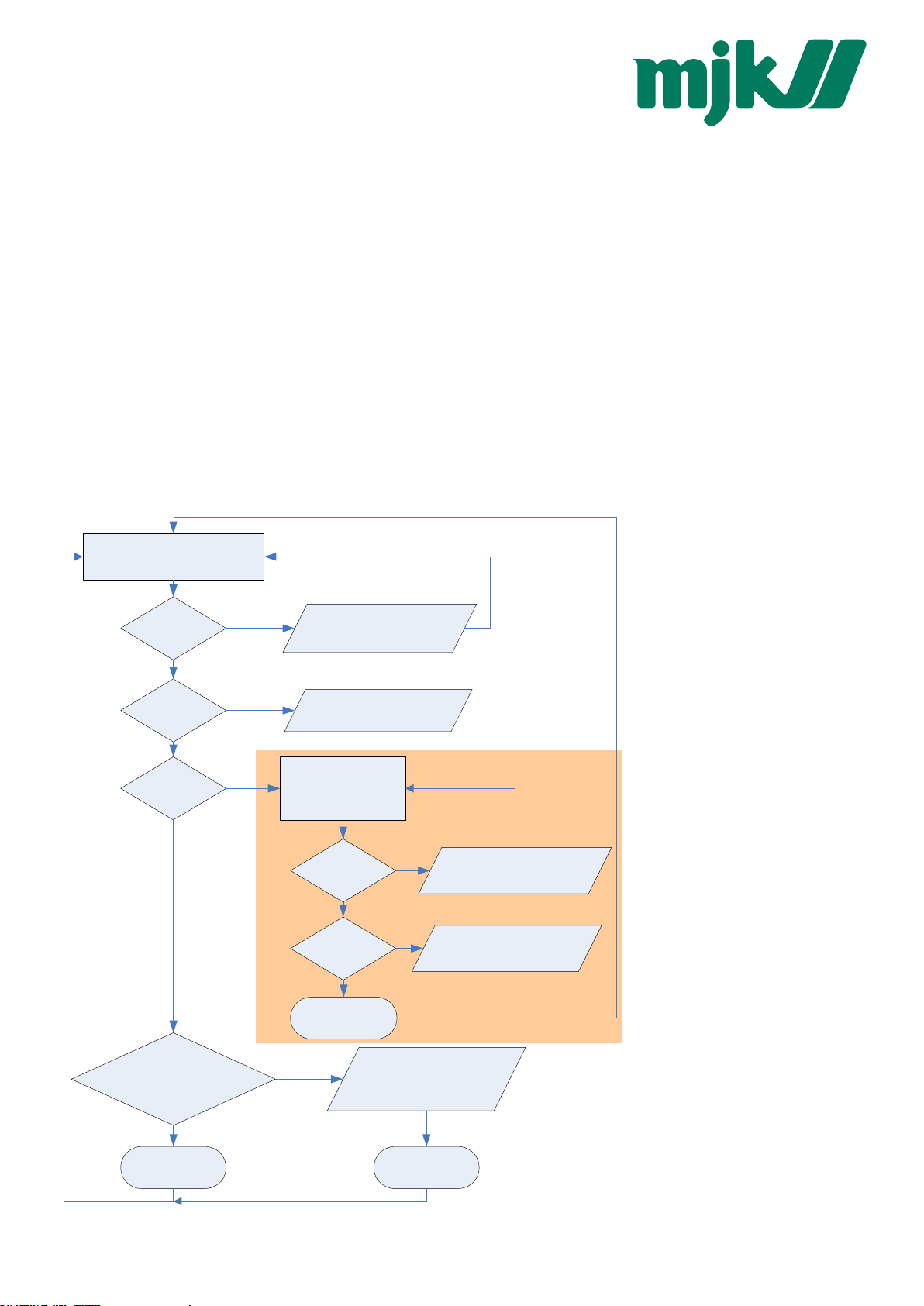
5.1 Example: read pressure value with exception handling
A simple example for reading out
Request P1, funct. 73:
250 73 1 161 167
a pressure value.
Because only one transmitter is
connected, the „transparent“
address 250 is used.
To read out pressure functions 73
Timeout
Transmission error
occured -> Log-File
and 48 are necessary. When the
slave replies with error no. 32
Exception
2 or 3
Invalid Channel or
message -> Check
your request
(device just recently started up,
power on), then this has to be
confirmed with function 48. This is
helpful to detect current supply
Exception:
32
Initialize, funct. 48:
250 48 4 67
Initialize: F48
interruptions (on the power supply
circuit).
Enhancement:
During start-up the device group
Timeout
Transmission error
occured -> Log-File
can be checked via function F48
to ensure that this version is
supported.
Further information is available:
Exception:
2
Incorrect length ->
Check your request
• F30: pressure and
temperature range
• F69 serial number
F48: o.k.
Check Staus Byte:
P1, TOB1, /Std:
STAT & 0b10010010 != 0?
Valid Value
received
See chapter:
Error handling and
recognition
Invalid Value
received
Communication protocol Serie30 Page 17/37
Page 12

Some examples:
Read P1
Read P2
Read
TOB1
Initialize
address
250
1
1
250
1
1
request response
250 73 1 161 167 250 73 63 109 186 172 0 26 27
1 73 1 80 214 1 73 63 109 177 83 0 231 97
1 73 2 81 150 1 73 63 109 178 242 0 119 232
250 73 4 162 103 250 73 65 201 184 0 0 224 204
1 73 4 83 22 1 73 65 202 81 128 0 95 54
1 48 52 0 1 48 5 20
received value
0.9286296 bar
0.9284870 bar
0.9285117 bar
25.21484 °C
25.28979 °C
FW=5.20-5.50,
Buffer=10, device
already initialized
5.2 Function 30: Read coefficient
Request:
DevAddr 30 Nr. CRC16_H CRC16_L
Response:
DevAddr 30 B3 B2 B1 B0 CRC16_H CRC16_L
Exception errors:
2 if no. > 111
3 if message length incorrect
32 if device is not yet initialised
Note:
Every coefficient can be read in IEEE754 format (floating-point format 4-byte B0 .. B3) via this function.
Æ Information on IEEE754: see appendix.
5.2.1 Calibration values
No. Description of coefficient Unit
53 Threshold value of the roof function bar
64 Offset of pressure sensor P1 bar
65 Gain factor of pressure sensor P1
66 Offset of pressure sensor P2 bar
67 Gain factor of pressure sensor P2
68 Offset of analogue output bar
69 Gain factor of analogue output
70 Offset of CH0
71 Gain factor of CH0
72 Upper threshold value for switching output 1**
73 Lower threshold for switching output 1**
78 Upper threshold value for switching output 2**
79 Lower threshold for switching output 2**
100… 111 free coefficients for customer use
** no longer supported for devices 5.20-10.XX and newer.
The calibration values can be read and written.
Communication protocol Serie30 Page 18/37
Page 13

5.2.2 Information values
No. Description of the coefficient Unit
80 Minimum pressure of sensor P1 bar
81 Maximum pressure of sensor P1 bar
82 Minimum pressure of sensor P2 bar
83 Maximum pressure of sensor P2 bar
84 Minimum temperature of temperature sensor °C
85 Maximum temperature of temperature sensor °C
86 Minimum temperature of sensor P1 °C
87 Maximum temperature of sensor P1 °C
88 Minimum temperature of sensor P2 °C
89 Maximum temperature of sensor P2 °C
90 Minimum value of channel CH0
91 Maximum value of channel CH0
92 Pressure for minimum analogue signal * bar
93 Pressure for maximum analogue signal * bar
94 Minimum analogue signal* mA , V
95 Maximum analogue signal* mA , V
* Required for scaling the analogue output (see below)
The information values are readable only.
The information for no. 94 and no. 95 may be in mA or V, according to whether the device possesses a voltage output or a
current output (function 100 index 3).
Only coefficients 68, 69 and 80 .. 95 are available for devices of Class.Group = 5.1.
5.2.3 Scaling of channels CH0, P1 and P2
CH0, P1 and P2 are linearly scalable with zero point and gain factor: Value = gain factor * value + offset
Standard values: Offset = 0.0, gain factor = 1.0
It is also possible to influence the offset values via function 95 (see function 95).
The gain factor should be used for calibration purposes only, and not to alter pressure units. The latter operation should
always be carried out by the master! In order to represent other pressure units via the analogue output, the unit conversion must
be taken into account when scaling the analogue output.
Communication protocol Serie30 Page 19/37
Page 14

5.2.4 Scaling the analogue output
The analogue output on the Series 30 pressure transmitters can be programmed via the interface. As the two routes sensorsignal
Æ
digital transformation and digital value Æ analogue signal are calibrated independently at the factory, the analogue
output can be set to different pressures or pressure units without requiring recalibration. For this purpose, KELLER offers the
MJK do
free READ30 software, which provides a convenient means of carrying out this scaling with a PC.
To programme the scaling of the analogue output yourself, proceed as follows:
Function 100 enables you to ascertain whether the device possesses an analogue output. The coefficients required for
calculation can be read out via function 30. A new scaling can be programmed via function 31.
For devices of Class.Group = 5.1 the new scaling must be updated via function 95 CMD = 4.
In the case of devices of Class.Group = 5.20 the analogue output is updated automatically.
Read-out of pressure range for the analogue output:
The following coefficients(K[no.]) must be read out via function 30 in order to calculate the lower and upper limit of the analogue
output:
A = (K[92] – K[68]) / K[69]
B = (K[93] – K[68]) / K[69]
Setting a new pressure range for the analogue output:
K[68] and K[69] must be calculated and written into the device via function 31:
K[68] = K[92] - ((K[93] – K[92]) / (B – A)) * A
K[69] = (K[93] – K[92]) / (B – A)
Whereby:
K[x]: Coefficient with the corresponding number [x] Æ see function 30
A: Pressure in bar at which the signal K[94] is to be output
B: Pressure in bar at which the signal K[95] is to be output
Other pressure units are to be converted into bar.
5.3 Function 31: Write coefficient
Request:
DevAddr 31 Nr. B3 B2 B1 B0 CRC16_H CRC16_L
Response:
DevAddr 31 0 CRC16_H CRC16_L
Exception errors:
2 If no. is not 53, 64 .. 73, 78, 79 or 100 .. 111
3 If message length is incorrect
32 If device has not yet been initialised
Note:
Information on scaling of the channels: See functions 73 and 95. Information on which channels are active: See function 100.
Device of Class.Group = 5.1: DAC scaling only, no. 68 and 69 can be specified.
Device of Class.Group = 5.20: No. 64 .. 71 can be specified.
Communication protocol Serie30 Page 20/37
Page 15

5.4 Function 32: Read configuration
Request:
DevAddr 32 Nr. CRC16_H CRC16_L
Response:
DevAddr 32 Dates CRC16_H CRC16_L
Exception errors:
2 If Nr. > 13
3 If message length is incorrect
32 If device has not yet been initialised
Remark:
See description function 33
5.5 Function 33: Write configuration
Request:
DevAddr 33 Nr. Dates CRC16_H CRC16_L
Response:
DevAddr 33 0 CRC16_H CRC16_L
Exception errors:
2 If Nr. > 13
3 If message length is incorrect
32 If device has not yet been initialised
Remark:
With those functions one can read and write some configuration of the device. This functions provide a single byte access and
replace function 100 / 101 for the devices with firmware Class.Group -Year.Week = 5.20-5.24 und earlier.
Communication protocol Serie30 Page 21/37
Page 16

Description:
Nr. Name Description Read Write
0 CFG_P Active pressure channels (high priority):
Bit 1: P1
Bit 2: P2
1 CFG_T Active Temperature channels (low priority):
Bit 3: T (Temperature sensor)
Bit 4: TOB1 (Temperature of pressure sensor P1)
Bit 5: TOB2 (Temperature of pressure sensor P2)
2 CFG_CH0 Calculated channel: Byte value (decimal)
0: inactive
1: Difference P1 – P2
2: Difference P2 – P1
3: Square root calculation sqrt(P1)
4: Square root calculation sqrt(P2)
5: Square root calculation sqrt(P1 – P2)
6: Square root calculation sqrt(P2 – P1)
7: SF6 Density with external temp. sensor
8: SF6 Normalized pressure at 20°C with an external temp. sensor
9: SF6 Density with TOB1
10: SF6 Normalized pressure at 20°C with TOB1
11: Absolute value abs(P1)
12: Absolute value abs(P1 – P2)
3 CNT_T Temperature measurement interval in seconds.
4 CNT_TCOMP
LP-FILTER
5 --
6 --
7 FILTER Filter setting for one conversion:
8 --
9 DAC Analogue output:
10 UART UART settings:
11 FILTER_ORG Factory setting for filter value.
12 STAT Status of the measurement. See function 73 for details.
13 DEV_ADDR Device address. Range: 1 .. 255.
Value of Bit 0 ... 3 (LowNibble): CNT_TCOMP
After CNT_T * CNT_TCOMP seconds a temperature compensation will be performed.
Value of Bit 4 ... 7 (HighNibble):Low pass filter for P1 and P2. LowpassFilter = 2
The formula for the low pass filter is given as:
terLowpassFil
P
=
n
1
+
P
: new filtered value
n+1
: actual measured value
P
n
: old filtered value
P
n-1
Bit 0: Adaptive filter for P1 and P2 (on / off)
Bit 1: Low pass filter for T, TOB1 and TOB2 (on / off)
Bit 2 .. Bit 4: Over sampling ration OSR = 2^
Bit 5 .. 6: Amount of samples per averaging: 0 ..3 = 1, 2, 4 or 8 values.
Factory settings see FILTER_ORG.
Bit 0: Milli Amperes output (4 .. 20mA)
Bit 1: Voltage output
Bit 4 = 1: P1 is linked to the analogue output
Bit 4 = 0: CH0 is linked to the analogue output
Scaling see function 30/31
Bit 0 .. 3: Baud rate
Baud rate Value = 0: 9’600baud
Baud rate Value = 1: 115’200baud
Bit 4: Parity selection. 0: no Parity, 1: Parity enable
Bit 5: Parity mode. 0: odd parity, 1: even parity
2
)12(
terLowpassFil
+⋅−
1
−
(8+Bit 2 ... 4)
PP
nn
where:
Bit 4 ... B7
D U
D U
D D
Device has to be
restarted.
Please note
that for some
settings there
are some
more
configuration
needed.
Contact
Keller for
details.
D D
D D
D D
D
(D: Bit4)
see below *
D D
D U
D U
D D
* : With firmware Class.Group -Year.Week = 5.20-10.40 and earlier: Change of bit4 is allowed (to link the analogue output either
to CH0 or P1).
Communication protocol Serie30 Page 22/37
Page 17

5.6 Function 48 : Initialise and release
Request:
DevAddr 48 CRC16_H CRC16_L
Response:
DevAddr 48 Class Group Year Week BUF STAT CRC16_H CRC16_L
Exception error:
3 If message length is incorrect
Note:
Each time the device is switched on by applying the supply voltage or after a break in the power supply, the device must be
initialised via this function. Calling a different function will lead to exception error 32.
The following information is returned:
Class Device ID code
5: Series 30 digital pressure transmitter (33, 35, 36, 39)
Group Subdivision within a device class
1: Series 30 transmitter from 1999 or later
20: Series 30 transmitter from 2002 or later
The differences between these devices are defined in italics in the functions.
Year, Week Firmware version
BUF Length of the internal receive buffer
STAT Status information
0: Device addressed for first time after switching on.
1: Device was already initialised
Communication protocol Serie30 Page 23/37
Page 18

5.7 Function 66 : Write and read new device address
Request:
DevAddr 66 NewAddr CRC16_H CRC16_L
Response:
DevAddr 66 ActAddr CRC16_H CRC16_L
Exception error:
3 If message length is incorrect
32 If device is not yet initialised
Note:
This function programmes the device addresses to NewAddr. The address is returned in ActAddr as confirmation. It is to be
ensured that the new address NewAddr is not already in use by another bus user.
Permissible addresses: 1 .. 249. Address 250 is transparent. This means that every device, irrespective of the set address, will
respond to address 250. Consequently, transparent DevAddr = 250 may only be used in stand-alone operating mode!
For the purpose of reading the device address when the address is not known, for example, the value 250 is transferred as
DevAddr and the value 0 is transferred as NewAddr. The current address is then returned in response.
5.8 Function 69 : Read serial number
Request:
DevAddr 69 CRC16_H CRC16_L
Response:
DevAddr 69 SN3 SN2 SN1 SN0 CRC16_H CRC16_L
Exception errors:
3 If message length is incorrect
32 If device is not yet initialised.
Note:
The serial number is allocated at the factory. It consists of 4 bytes and is calculated as follows :
3
SN = 256
* SN3 + 256 2 * SN2 + 256 * SN1 + SN0
Communication protocol Serie30 Page 24/37
Page 19

5.9 Function 73 : Read value of a channel (floating point)
Request:
DevAddr 73 CH CRC16_H CRC16_L
Response:
DevAddr 73 B3 B2 B1 B0 STAT CRC16_H CRC16_L
Exception errors:
2 If CH > 5
3 If message length is incorrect
32 If device is not yet initialised
Note:
A device can measure up to five signals (channels):
Two independent pressure sensors, P1 and P2. Plus the temperatures of pressure sensors TOB1 and TOB2 respectively. The
temperatures of the pressure sensors (TOB1, TOB2) are required for temperature compensation of the pressure signal. A
temperature sensor ( T ) can also be measured.
Please use function 32 to get the information which Channels are active.
CH0 is a calculated channel whose mode of functioning is defined in function 100.
On a standard pressure transmitter, only channels P1 and TOB1 are available. You can read out which channels are active via
function 100.
The measured value is returned in IEEE754 format (4-byte B0 ... B3).
CH Name Description Unit
0 CH0 Calculated channel (see function 32,33,100) *
1 P1 Pressure from pressure sensor 1 bar
2 P2 Pressure from pressure sensor 2 bar
3 T Additional temperature sensor °C
4 TOB1 Temperature of pressure sensor 1 °C
5 TOB2 Temperature of pressure sensor 2 °C
* Dependent on definition in function 32 or 100.
The STAT byte contains the current status.
Bit position .7 .6 .5 .4 .3 .2 .1 .0
Name /STD ERR2 TOB2 TOB1 T P2 P1 CH0
A set /STD bit indicates whether the transmitter is in Power-up mode, otherwise it is in Standard mode.
A set ERR2 bit denotes that a computation error has occurred in the calculation process for the analogue output. This occurs if
the analogue Signal is in saturation (depends on the scaling)
A set CH0, P1, P2, T, TOB1, TOB2 bit indicates that a measuring or computation error has occurred in the channel concerned.
For details in error-handling see chapter Error handling and recognition!
Communication protocol Serie30 Page 25/37
Page 20

5.10 Function 74 : Read value of a channel (integer)
Request:
DevAddr 74 CH CRC16_H CRC16_L
Response:
DevAddr 74 B3 B2 B1 B0 STAT CRC16_H CRC16_L
Exception errors:
2 If CH > 5
3 If message length is incorrect
4 If a channel is in overflow/underflow/inactive state or the data is invalid
32 If device has not yet been initialised
Note:
Only in devices of Class.Group = 5.20.
Same as function 73, but values in 4-byte integer (long) B0 .. B3, where B3 is MSByte. The resolution is reduced to 0.1mbar.
Unit: CH0, P1 and P2: in Pascal (1Pa = 10
-5
bar).
T, TOB1 and TOB2: in 0.01°C
Status-Byte (STAT): See function 73.
For details in error-handling see chapter Error handling and recognition!
Communication protocol Serie30 Page 26/37
Page 21

5.11 Function 95 : Commands for setting the zero point
Requests:
Request a:
DevAddr 95 CMD CRC16_H CRC16_L
Request b with setpoint:
DevAddr 95 CMD
B3 B2 B1 B0
where B3:B0: Floating-piont number IEEE754 format (4-byte B0 ... B3) for the setpoint.
Response:
DevAddr 95 0 CRC16_H CRC16_L
Exception errors:
1 If in Power-up mode
2 If CMD invalid
3 If message length incorrect
32 If device is not yet initialised
Note:
The following actions can be carried out with this function:
CMD Meaning
0
Set zero point of P1
1
Reset zero point of P1 to standard value
2
Set zero point of P2
3
Reset zero point of P2 to standard value
4
Update DAC scaling (
5
--
6
Set zero point of CH0
7
Reset zero point of CH0 to standard value
Class.Group = 5.1 only)
CRC16_H CRC16_L
CMD 0, 2, 6:
Zero point values for pressure channels P1, P2 and the calculated channel CH0. These values can also be read via function 30
and written via function 31.
Request a: The zero point is calculated such that the current measured value = 0.0.
Request b: The zero point is calculated such that the current measured value equals the setpoint (B3:B0).
CMD=6, CMD=7 and request b are only available in devices of Class.Group 5.20.
CMD 1, 3, 7: Reset zero point to factory setting
The zero point values are reset to 0.
Devices with zeroing button:
The devices may optionally possess a zeroing button. The zero point is then set as follows by means of this button:
If only P1 is active, the zero point value of P1 is calculated such that P1 = 0.
If channels P1 and P2 are active, the zero point value of P2 is calculated such that P2 = P1.
Communication protocol Serie30 Page 27/37
Page 22

5.12 Function 100 : Read configuration
Request:
DevAddr 100 Index CRC16_H CRC16_L
Response:
DevAddr 100 PARA0 PARA1 PARA2 PARA3 PARA4 CRC16_H CRC16_L
Exception errors:
2 If index > 8
3 If message length is incorrect
32 If device is not yet initialised
Note:
This function supplies the information about the configuration of the device. Please use Function 32 instead of this function for
devices of Class.Group 5.20-5.24 and earlier. With function 32/33 you have access to a single parameter instead of all five
parameters.
A pressure transmitter can read two independent pressure sensors (P1 and P2), plus the temperatures of the respective
pressure sensors (TOB1 and TOB2) and an independent temperature ( T ).
Index Para0 Para1 Para2 Para3 Para4
0
CFG_P CFG_T CFG_CH0 CNT_T High Nibble | Low Nibble
2
SWITCH FILTER DAC
3
UART FILTER_ORG
LP-Filter | CNT_TCOMP
For details see description of the parmeters in function 101.
5.13 Function 101 : Write configuration
Request:
DevAddr 101 Index Para0 Para1 Para2 Para3 Para4 CRC16_H CRC16_L
Response:
DevAddr 101 0 CRC16_H CRC16_L
Exception errors:
2 If wrong index
3 If message length is incorrect
32 If device is not yet initialised
Note:
This function supports altering of parameters. Please use Function 32 instead of this function for devices of Class.Group 5.20-
5.24 and earlier. With function 32/33 you have access to a single parameter instead of all five parameters.
Please note: With this function all five parameters (para0 .. para4) will be overwritten. To change a single parameter of the said
index all five parameters must be first read out with function 100. Now you can alter the desired parameter without accidentally
changing anything in the other four.
An incorrect parameter can damage the instrument!
Communication protocol Serie30 Page 28/37
Page 23

Description of the parameters for function 100 and 101:
Parameter Description Read Write
CFG_P Active pressure channels (high priority):
Bit 1: P1
Bit 2: P2
CFG_T Active Temperature channels (low priority):
Bit 3: T (Temperature sensor)
Bit 4: TOB1 (Temperature of pressure sensor P1)
Bit 5: TOB2 (Temperature of pressure sensor P2)
CFG_CH0 Calculated channel: Byte value (decimal)
0: inactive
1: Difference P1 – P2
2: Difference P2 – P1
3: Square root calculation sqrt(P1)
4: Square root calculation sqrt(P2)
5: Square root calculation sqrt(P1 – P2)
6: Square root calculation sqrt(P2 – P1)
7: SF6 Density with external temp. sensor **
8: SF6 Normalized pressure at 20°C with an external temp. sensor **
9: SF6 Density with TOB1 **
10: SF6 Normalized pressure at 20°C with TOB1 **
11: Absolute value abs(P1)
12: Absolute value abs(P1 – P2)
CNT_T All CNT_T seconds a temperature measurement will be performed.
CNT_TCOMP
LowNibble
LP-FILTER
HighNibble
SWITCH** Switch:
FILTER Filter setting for one conversion:
DAC Analogue output:
UART UART settings:
FILTER_ORG Factory setting for filter value.
Value of Bit 0 ... 3 (LowNibble) = CNT_TCOMP.
After CNT_T * CNT_TCOMP seconds a temperature compensation will be performed.
Value of Bit 4 ... 7 (HighNibble) = LP-Filter:
Low pass filter for P1 and P2 (if active). LowpassFilter = 2
The formula for the low pass filter is given as:
terLowpassFil
P
=
n
1
+
P
: new filtered value
n+1
: actual measured value
P
n
: old filtered value
P
n-1
The value of Bit 0 .. 2 gives the information witch channel is linked to the switch:
Value= 0: Calculated Channel CH0
Value= 1: P1
Value= 2: P2
Bit 3: Switch output is active if this bit is set.
Bit 0: Adaptive filter for P1 and P2 (on / off)
Bit 1: Low pass filter for T, TOB1 and TOB2 (on / off)
Bit 2 .. Bit 4: Over sampling ration OSR = 2^
Bit 5 .. 6: Amount of samples per averaging: 0 ..3 = 1, 2, 4 or 8 values.
Factory settings see FILTER_ORG.
Bit 0: Milli Amperes output (4 .. 20mA)
Bit 1: Voltage output
Bit 4 = 1: P1 is linked to the analogue output
Bit 4 = 0: CH0 is linked to the analogue output
Scaling see function 30/31
Bit 0 .. 3: Baud rate
Baud rate Value = 0: 9’600baud
Baud rate Value = 1: 115’200baud
Bit 4: Parity selection. 0: no Parity, 1: Parity enable
Bit 5: Parity mode. 0: odd parity, 1: even parity
2
*)12(
terLowpassFil
+−
1
−
(8+Bit 2 ... 4)
PP
nn
where:
Bit 4 ... B7
D U
D U
D D
D D
D D
D U
D D
D U
D D
D U
** no longer supported for devices Class.Group 5.20-10.XX and later
Device has to be
restarted.
Please note
that for some
settings there
are some
more
configuration
needed.
Contact
Keller for
details.
Communication protocol Serie30 Page 29/37
Page 24

6 Appendix
6.1 Interface converter
The serial RS232 interface or the USB interface can be used for connection to a PC. KELLER offers converters for this purpose.
Various other products are commercially available, however. The following requirements apply when working with KELLER
MJK do
MJK
software:
- The converter must control transmit / receive switch-over automatically.
- KELLER converters feature a hardware echo, i.e. the transmitted message is received again immediately as
The MJK
an echo. This echo is required by some KELLER software programmes.
MJK -
6.2 floating-point format IEEE754
As data transmission is effected byte-wise (8-bit data), the floating-point values are represented as follows :
B0: Bit 0..7; B1: Bit 8..15, B2: Bit 16..23, B3: Bit 24..31
Representation in accordance with IEEE754:
B3 DATA H (Reg. 0) B2 DATA L (Reg. 0) B1 DATA H (Reg. 1) B0 DATA L (Reg. 1)
b01000001 (0x41) b00101001 (0x29) b00000010 (0x02) b11011110 (0xDE) Valid Number
b01111111 (0x7F) b10000000 (0x80) b00000000 (0x00) b00000000 (0x00)
b11111111 (0xFF) b10000000 (0x80) b00000000 (0x00) b00000000 (0x00)
∞ / Overflow
-∞ / Underflow
bx1111111 (0xFF) b11111111 (0xFF) b11111111 (0xFF) b11111111 (0xFF) Not a Number
1 bit Sign + 8 bit Exponent + 23 bit Mantis = 32 bit
Calculation of the value transmitted:
127
−
V
S
E
M
2)0.1()1(
⋅+⋅−=
23
2
0 = 0
10000010 = 130
01010010000001011011110 = 2687710
-10 * (1.0 + 2687710/8388608) * 2
130-127
= 10.5631999969482421875
These values directly show the value in the requested unit [bar] or [°C].
Ö10.5632 bar
Usage of Keller software:
If you use the DLL which is available from KELLER, you do not need to carry out conversion, as this is encapsulated in the DLL.
MJ K ,
If you wish to address the devices directly, however, you must convert the individual bytes into a floating-point value.
To obtain a floating-point value from the individual bytes, proceed as follows:
1. Define data structure in which an array of 4 bytes and a 32-bit floating-point value is defined at the same memory
location.
2. Write the bytes into the byte array.
3. Read out the floating-point value.
You do not need to carry out any actions, therefore, as the computer attends to interpretation. Some microcontrollers have a
different data structure for floating-point values. In such cases, adaptation is necessary.
Further information is to be found at:
http://cch.loria.fr/documentation/IEEE754/numerical_comp_guide/ncg_math.doc.html - 556
Communication protocol Serie30 Page 30/37
Page 25

6.3 Error handling and recognition
The electronic unit can read five signals: pressure values from two pressure sensors (P1, P2), temperature values from both of
these pressure sensors (TOB1, TOB2) and temperature value from one additional temperature sensor (T). Additionally, out of
these values an other value can be calculated (CH0). These values are described as channels in this documentation.
To check if the channels are active one may use function F32 (or MODBUS addresses 0x0204-0x0206) (refer to according
chapter).
Measuring range
The signals are being measured with an analogue to digital converter (DAC). The measuring range is limited upwards and
downwards.
For the pressure signals P1 and P2 the limitation is depending on the compensated pressure range, which can be read out with
function 30 (as well as MODBUS function 3 [range 0x03xx] from version 5.20-10.x and later).
Readable range: (pressure range minimum – 10%) up to (pressure range maximum + 10%)
Is the pressure below or above this range, then the bit in the Status-Byte will be set. The measured value itself is no longer valid
when the Status-Bit is set.
Dependencies
P1 and P2 are temperature-compensated and therefore they are depending on temperature. Channel CH0 is always depending
on P1 and / or P2 and on a temperature channel. Is there a fault in one of these dependencies so the depending channel will
follow accordingly.
6.3.1 What is new in version 5.20-10.40 (and later)
Version 5.20-10.40 (available end of 2010) and later will display additionally to the Status-Bit also an error in the value itself.
The format follows the special indications according to floating point arithmetic: NaN, +Inf (ovl), -Inf (uvl). See chapter floating-
point Format IEEE754.
CH0 P1/P2 TOB1/TOB2
NaN
Dependency error (P1, P2 = NaN or +/-
+/-Inf in compensating T-channel -
Inf)
+Inf
- ADC value out of range (Overflow) ADC value out of range (Overflow)
T > 300 °C
-Inf
- ADC value out of range (Underflow) ADC value out of range (Underflow)
T < - 70°C
0.000
Sqrt( < Pcutoff ) - -
The values NaN, +Inf and –Inf are defined in the IEEE754 standard and are described in chapter floating-point format IEEE754.
NaN is also shown, when the requested channel is not active. In this case, the Staus-Bit is not set.
Integer Values (Function 74):
ovl Æ 2147483647
uvlÆ -2147483648
NaN Æ 2147483647
Communication protocol Serie30 Page 31/37
Page 26

6.3.2 Analogue Output
The analogue output has to transfer the error states described in the former chapter and therefore additional analogue states
were introduced. The graph below shows the transfer function between pressure ( in this example the analogue output is a
function of P – however it could also be some other mathematical function using CH0). The black line showes the transfer
function for a positive DAC-gain. The Sig
is independent of any scaling function and represents a internal error state (see
error
table above).
The following table shows possible analogue values for different hardware types:
0-10 V 0-2.5 V 4-20 mA Dig. represantive
Sig
Sig
Sig
Sig
Sig
error
ovl
max
min
uvl
11.6 V 2.9 V 22.5 mA NaN
11 V 2.75 V 21.8 mA +Inf
10 V 2.5 V 20 mA value
0 V 0 V 4 mA value
-1 V -0.3 V 3.3 mA -Inf
Communication protocol Serie30 Page 32/37
Page 27

6.4 Calculation of the CRC16 checksum
The checksum can either be calculated or derived from a table.
Here is an example of CRC16 calculation in C:
//////////////////////////////////////////////////////////////////////////
// CRC-16 calculation in C
//
// Calculation of CRC-16 checksum over an amount of bytes in the serial buffer.
// The calculation is done without the 2byte from crc16 (receive-mode).
// SC_Buffer[]: Byte-Buffer for the serial interface. Type: unsigned char (8bit)
// SC_Amount : Amount of Bytes which should be transmitted or are received (without CRC16)
//
//////////////////////////////////////////////////////////////////////////
void CalcCRC16(unsigned char* CRC_H, unsigned char* CRC_L)
{
// locals
unsigned int Crc;
unsigned char n, m, x;
START
// initialisation
Crc= 0xFFFF;
m= SC_Amount;
x= 0;
// loop over all bits
while(m>0)
{
Crc^= SC_Buffer[x];
for(n=0; n<8; n++)
{
if(Crc&1)
{
Crc>>= 1;
Crc^= 0xA001;
}
else
Crc>>= 1;
}
m--;
x++;
}
// result
*CRC_H= (Crc>>8)&0xFF;
*CRC_L= Crc&0xFF;
}// end CalcCRC16
yes
CRC := $FFFF
N := 0
CRC := CRC xor DATA[N]
M := 0
CRC mod 2
= 1
CRC := CRC div 2
M := M + 1
M < 8
yes
CRC := CRC div 2
CRC := CRC xor $A001
yes
N := N + 1
N < Message
STOP
This results in the following calculation for function 48 with device address 250: CRC16_H= 4, CRC16_L= 67.
Examples showing use based on a table are to be found in the MODBUS documentation at:
http://www.modbus.org
Communication protocol Serie30 Page 33/37
Page 28

6.5 Description of the software driver (DLL)
6.5.1 General
The available DLL s30c.dll has been tested on the Windows 95, 98, NT and 2000 operating systems.
Examples of the use of this DLL are available for the following programming languages:
- LabVIEW
- C++
- Delphi
- VB
- VBA
The call convention stdcall is used for assigning the parameters to the functions. This means that:
− all parameters are passed via the stack,
− the parameter furthest to the right is calculated and passed first, the parameter furthest to the left is calculated and passed
last,
− the function itself deletes the parameters from the stack.
As the declarations for the functions presented below show, many variables are declared with the prefixed word var. This means
that these variables are passed as pointers and not as values.
The types employed for declaration purposes are described below:
Type Range Format
Byte 0..255 8-bit without sign
Word 0..65535 16-bit without sign
Smallint -32768..32767 16-bit with sign
Longint -2147483648.. 2147483647 32-bit with sign
Pbyte Pointer to byte
Single +/- 1.5x10
-45
..3.4x1038 32-bit
6.5.2 The functions of the DLL
Each function returns a value which indicates whether the desired function has been successfully executed or not. All the
possible return values are specified below. The returned parameters are only valid and may only be processed if the function
concerned has been successfully executed.
Return value Description
RS_OK 0 Function successfully executed; return parameters are valid
RS_EX1 1 Function successfully executed; but exception error 1 has occurred
RS_EX2 2 Function successfully executed; but exception error 2 has occurred
RS_EX3 3 Function successfully executed; but exception error 3 has occurred
RS_EX32 32 Function successfully executed; but exception error 32 has occurred
RS_BROADCAST 100 Broadcast
RS_ERROR -1 General error
RS_TXERROR -2 Transmit error
RS_RXERROR -3 Receive error in UART
RS_TIMEOUT -4 No data or insufficient data received
RS_BADDATA -5 Data erroneous (e.g. CRC16 erroneous)
Communication protocol Serie30 Page 34/37
Page 29

6.5.2.1 Port functions
The devices are connected to the PC via a serial interface. The port functions serve to open and close this interface. Ports 1 to 9
(COM1..COM9) are valid. The standard setting should be used for the timeout time (Timeout = 0). When the desired port has
been successfully opened, the OpenComPort function returns the value RS_OK, otherwise RS_ERROR.
An open port is closed automatically on ending the programme.
It is additionally possible to set the baud rate and the data format via the OpenComExt function. KELLER devices only support
The MJK
9600 baud. Exception: Transmitters with firmware 5.20 can also be operated at 115’200 baud. Use the READ30 software from
MJ K -
KELLER to change the transmitter’s baud rate.
As a standard setting, no parity is used (none). This results in a data format of 10 bits per byte. If parity is active, the data format
is 11 bits per byte.
function OpenComPort( intPort, intTimeout: Smallint ): Smallint; stdcall; export;
function OpenComExt( intPort, intTimeout: Smallint; longBaud: Longint; intParity:Smallint
): Smallint; stdcall; export;
intParity: 0: no parity bit (sStandard), 1: odd parity bit, 2: even parity bit
longBaud: 9600 for 9600 baud, 115'200 for 115’200 baud (devices with firmware 5.20)
function CloseComPort : Smallint; stdcall; export;
6.5.2.2 Echo function
Interface converters from KELLER Druckmesstechnik always supply an echo of the message transmitted by the PC.
This function has the standard value 1 (Echo On), to enable operation with the converters supplied by KELLER. If other
MJK Automation A/S will
MJK A/S
converters are used which do not supply a hardware echo, the function must be set to 0 = Echo Off .
function EchoOn( bteEcho: Byte ): Smallint; stdcall; export;
Communication protocol Serie30 Page 35/37
Page 30

6.5.2.3 Protocol functions
The following functions encapsulate the above-described bus functions. The parameter sequences are identical. The CRC16
checksum is not included here, as it is calculated and checked in the DLL. Some parameters consist of several bytes. These are
grouped together for the sake of clarity. The different requests a and b pertaining to function 95 are split into two functions: F95
and F95val.
Functions F34, F35, F64, F65 and F101 are only listed here for the sake of completeness, and are of no relevance in these
devices. Function F32 and F33 are new functions which are aviable in the s30c.dll from the 12.9.2005 and later.
function F30( bteDeviceAddr, bteCoeffNo: Byte; var sinCoeff: Single
): Smallint; stdcall; export;
function F31( bteDeviceAddr, bteCoeffNo: Byte; sinCoeff: Single
): Smallint; stdcall; export;
function F32( bteDeviceAddr, bteCoeffNo: Byte; var sinCoeff: Byte
): Smallint; stdcall; export;
function F33( bteDeviceAddr, bteCoeffNo: Byte; sinCoeff: Byte
): Smallint; stdcall; export;
function F34( bteDeviceAddr: Byte; wrdAddr: Word; bteAmount: Byte; pbteData: PByte
): Smallint; stdcall; export;
function F35( bteDeviceAddr: Byte; wrdAddr: Word; bteAmount: Byte; pbteData: PByte
): Smallint; stdcall; export;
function F48(
bteDeviceAddr: Byte; var bteClass, bteGroup, bteYear, bteWeek, bteBuffer, bteState: Byte
): Smallint; stdcall; export;
function F64( bteDeviceAddr: Byte; wrdAddr: Word; bteAmount: Byte; pbteData: PByte
): Smallint; stdcall; export;
function F65( bteDeviceAddr: Byte; wrdAddr: Word; bteAmount: Byte; pbteData: PByte
): Smallint; stdcall; export;
function F66( bteDeviceAddr, bteNewAddr: Byte; var bteActualAddr: Byte
): Smallint; stdcall; export;
function F69( bteDeviceAddr: Byte; var linSN: Longint
): Smallint; stdcall; export;
function F73( bteDeviceAddr, bteChannel: Byte; var sinValue: Single; var bteStat: Byte
): Smallint; stdcall; export;
function F95( bteDeviceAddr, bteCmd: Byte
): Smallint; stdcall; export;
function F95val( bteDeviceAddr, bteCmd: Byte; sinVal: Single
): Smallint; stdcall stdcall; export;
function F100(
bteDeviceAddr, bteIndex: Byte; var btePara0, btePara1, btePara2, btePara3, btePara4: Byte
): Smallint; stdcall stdcall; export;
function F101(
bteDeviceAddr, bteIndex: Byte; btePara0, btePara1, btePara2, btePara3, btePara4: Byte
): Smallint; stdcall stdcall; export;
Communication protocol Serie30 Page 36/37
Page 31

6.6 Changes
• Function 95, request b: For devices of Class.Group -Year.Week = 5.1-02.27 the setpoint must be multiplied by -1.
Document version 2.1, 19. October 2005: New function 32 and 33 for device Class.Group -Year.Week = 05.24 and
•
earlier
F75: cancelled.
•
Document version 2.2, 16. August 2006:
Description for function 32/33 revised.
Documentation of function 101 added.
Formula for scaling of the analogue output corrected.
•
Document version 3.0, 20. December 2010:
Added Modbus (chapter 4) support for Class.Group=5.20-10.XX
Modbus Implementation of Functions (3,6,8 and 16) with support of all functions covered by the Keller Bus protocol.
Removed SF6 calculations and Switch for devices Class.Group=5.20-10.XX
Added chapter error handling and recognition
Modified chapter “floating-point format IEEE754”
6.7 Software versions
An overview of the realeased versions for Class.Group 5.20:
Version
Year.Week
2.40
3.50
5.50
10.40
Date of
Major changements
production
2002..2003 Base version
2003 .. 2006 - CH0: add option Linepressure compensation
2006 .. 2100 - Hardware redesign to increase robustness under EMC
- add Lowpass Filter and adaptive Filter for pressure channels
- Switch2 canceled
- only two temperature channels possible: TOB1 and TOB2 or T
- sqrt calculation without scaling factor
- add Fct 32 and F33 for configuration access
2011… - Improoved errorhandling: see error handling and recognition
- Switch output: canceled
- CH0: SF6 calculation: canceled
- CH0: Kuve fitting added (CH0= 14)
MODBUS protocol:
- F3: access to all registers as in the KELLER protocol.
MJK
- Serial buffer increased from 10 to 13Bytes Æ readout of 2 values possible in one
task
- F6, F8, F16 added: Configuration an calibration also with MODBUS
- Debug: CRC of exception code was wrong
6.8 Support
We are pleased to offer you support in implementing the protocol.
There are two softwares aviable for readout values and for configuration: CCS30 and READ30.
Also divers for LabView, C#, etc are aviable on our website: http://www.keller-druck.com
KELLER AG für Druckmesstechnik
St. Gallerstrasse 119 • CH-8404 Winterthur
Tel: ++41 52 235 25 25
http://www.keller-druck.com
Communication protocol Serie30 Page 37/37
Page 32

2.3 RS485 half-duplex details
To ensure best possible operation in an industrial environment Keller uses RS485 driver with tailored characteristics. To provide
compatibility and get full advantage the bus driver of the master device has to support these specifications.
slew rate limited In order to avoid oscillations and interference the signal slew rate is limited. This measure
allows also usage of standard cables or non-standard topologies (e.g. level detectors or
branch lines >> 14m). The more, termination is less critical and has not to be implemented
compulsory at the line ends, a feature important for level detectors.
fail safe Defined signal level – even in short or open circuit case. This is very important for half-
duplex operation if all devices are in reception mode – here the line is open in case that no
bias resistors are implemented at the master.
1/8 unit load Input impedance is lower than defined by the RS485 standard, this allows connecting up to
128 devices to the bus.
Termination
Layout: between A and B at the beginning and the end of the transmission line
Value: the same as the line-impedance. Typ.: 120Ohm.
In case of a fail-safe master driver (interface converter to the PC) and a noise-free environment the termination resistor are not
mandatory. To reduce current peaks the resistor value can be chosen higher (1kOhm) or omitted (while transmitting the current
needed for 2x120Ohm is about 50mA).
To ensure a stable communication at least one terminal resistor is necessary (mostly included in the master-RS485 driver)!
One can do without a terminal resistor, if the environment is free of interference and the cable is held short (a few meters).
If the transmitter has additionally an analogue 4...20mA (two wire) output which will be used simultaneously with the serial
communication, it could be useful to communicate without terminal resistor. Otherwise the analogue current signal will have
heavy interferences. See application note: App. Note S30X-011 RS485 and current loop.pdf
The transmitters will never have a terminal resistor built in internally.
Bias-resistors
To keep up having always defined voltages one can switch pull-up respectively pull-down resistors to the transmitter:
From A to +5V and from B to GND. This is necessary when such RS485 drivers are in use which are not fail-save. This is not
necessary for our products when the master is fail-safe.
Common Mode
The common-mode of the data circuit line is +12 / -7V down to GND. It is essential to keep up with this. Always connect the GND
of the RS485 converter of the master with GND of the transmitter!
Definition of data circuit line assignments
signal Designation of Keller and
divers manufacturers…
Designation of the EIA
Standard
inverted (-) B A
non-inverted (+) A B
Further information on RS485: http://www.maxim-ic.com/MaximProducts/Interface/rs-485.htm
Communication protocol Serie30 Page 4/37
Page 33

3 Data-link layer
This section describes how data interchange is effected on this bus. The data and their check and control structures are grouped
together to form messages. These constitute the smallest communication unit, i.e. only messages can be exchanged between
the devices. As a half-duplex protocol is in use here, only one device can use the bus as a transmitter at any one time. All other
devices are then in receiver mode. The master takes the form of a PC or microcontroller, for example, and the devices are the
slaves. Each message exchange takes place under the control of the master. The message contains the address for the
receiving slave.
This results in the following 2 options for data interchange :
a) Broadcasting This mode of communication enables the master to transmit a message to all slaves
simultaneously. The master does not receive a reply, however, and is thus unable to check whether
the message has been correctly received by every slave.
b) Data interchange This mode of communication enables the master to communicate with a single slave. This normally
involves the transmission of two messages: the master transmits a request and the slave responds
to this request. Only the master is permitted to request a response. The request is received by every
slave, but only the selected slave responds. The response must be received within a stipulated time,
otherwise the master will assess the attempt as failed and must transmit the request again.
3.1 Transmission format for the serial interface
The data are transmitted serially via the bus. The following format applies:
• 1 start bit
• 8 data bits (the least significant bit first)
• 1 stop bit
• no parity (default)
• 9600 baud (default) or 115’200 Baud
This results in 10 bits (11 bits with active parity bit) per transmission byte.
Communication protocol Serie30 Page 5/37
Page 34

3.2 Format of a message
3.2.1 Format of the message sent by the master
Note on the presentation of messages: Each box presents 1 data byte consisting of 8 bits, unless otherwise stated.
Each message sent by the master possesses the following format:
DevAddr 0 Function
code
n byte parameters
(optional)
KELLER:CRC16_H
MODBUS:CRC16_L
KELLER:CRC16_L
MODBUS:CRC16_H
• DevAddr: Address of the device.
Address 0 is reserved for broadcasting.
Addresses 1...249 can be used for bus mode.
Address 250 is transparent and reserved for non-bus mode. Every device can be contacted with this address.
Addresses 251...255 are reserved for subsequent developments.
• Function code: Function number
A function is selected and executed by the device via the function number. The function number is encoded in 7 bits. Bit
7 is always 0. The functions are described further below.
• Parameters: The parameters required by the function (n = 0 .. 6, according to function)
• CRC16: 16-bit checksum
These two check bytes serve to verify the integrity of the received data. If an error is established, the entire message
will be discarded. The principle employed for CRC16 calculation is described in the appendix. The CRC16 standard is
applied here.
Note: The length of a message from the master is at least 4 bytes.
3.2.2 Format of the message sent by the slave
A message transmitted by the slave possesses the following format:
DevAddr X Function
code
n byte data
(optional)
KELLER:CRC16_H
MODBUS:CRC16_L
KELLER:CRC16_L
MODBUS:CRC16_H
• DevAddr: Address of the device. This address corresponds to the address of the responding device.
• Function code:
The function number is identical to the function number sent by the master. If the most significant bit is X = 0, this
indicates that the function has been executed correctly. If bit X = 1, an exception error has occurred.
• Data: Any data requested via the function follow here.
• CRC16: See above.
Note: A message from the slave has a minimum length of 5 bytes, and a maximum length of 10 bytes.
Communication protocol Serie30 Page 6/37
Page 35

3.3 Principle of message interchange
3.3.1 General rules
• An address may only be allocated to one device connected to the bus. If two devices on the bus have the same address,
both will respond, leading to a conflict.
• Every data interchange is initiated by the master. This means that a device may only transmit data if requested to do so by
the master.
• A message consists of several bytes. These bytes are transmitted without any interruption.
Maximal time between two bytes:
1.5ms @ 9600 baud (1.5 byte length)
0.20 ms @ 115200 baud (2.3 byte length)
If the time beween two bytes exceed the specified time, the slave ignores the received data, because of wrong message
length or CRC value. In that case the answer is omitted.
• The addressed device must respond within time T
otherwise the message will be invalid.
1,
Bit frame:
ST D0 D1 D2 D3 D4 D5 D6 D7 SP ST D0 … D6 D7 SP
ST: start bit, SP: stop bit. A parity bit (if active) is inserted before the SP, D0 .. D7: 8 data bits
Message frame:
Master:
Request
Slave:
Response
Master:
Request
T1
T
2
Response times:
• T
: Time between receipt of inquiry and beginning of response.
1
Min. 1ms to max. 100ms for all functions and devices.
Most functions (except those with EEPROM access like information values):T
• T
: Time to ready-to-receive state for the slave:
2
min. 1.2… 3ms
1
min 1 ms @ 9600 baud (1 byte length)
min 0.10 ms @ 115200 baud (1 byte length)
3.3.2 Treatment of errors
2 types of errors may occur during the interchange of messages between master and slave: transmission errors and exception
errors.
3.3.2.1 Transmission errors
These errors are primarily accountable to line faults. The message format is incorrect. The following problems are possible :
• A received message is too short. Æ e.g. too much of time gap in frame between the bytes.
• A message is longer than the internal transmission buffer permits.
• The word length cannot be interpreted correctly.
• The CRC16 checksum is incorrect.
In these cases the slave denies the request and will therefore not reply. This will lead to a timeout at the master. → the request
has to be repeated again.
In response to a transmission error, all received data are ignored. The slave remains in receive mode while the master is
required to initiate a new data interchange.
Communication protocol Serie30 Page 7/37
Page 36

3.3.2.2 Exception errors
The message has been received correctly (no transmission error has occurred), but the transmitted function number and/or the
parameters are invalid. The slave responds with an exception error, unless the message has been received in broadcasting
mode.
The message transmitted as a response by the slave has the following format:
DevAddr
Function
1
code
Exception
code
KELLER:CRC16_H
MODBUS:CRC16_L
KELLER:CRC16_L
MODBUS:CRC16_H
4 types of exception errors are defined :
• non-implemented function 1
• incorrect parameters 2
• erroneous data 3
• initialisation (only KELLER bus) 32
only MJK bus
Exception error 32 occurs when the device is started up anew and initialisation has not been carried out. This happens every
time the device is connected anew after a break in the power supply.
again
Communication protocol Serie30 Page 8/37
Page 37

4 MODBUS communication
4.1 MODBUS Communication Basics
Mode: RTU Mode (ASCII is not supported)
Coding System: 8–bit binary, hexadecimal 0–9, A–F
Two hexadecimal characters(bytes) contained in each 8–bit field of the message
Bits per Byte: 1 start bit
8 data bits, least significant bit sent first
1 parity bit: none, even, odd (programmable) – default: none (Keller devices)
MJK Devices
1 stop bit
Error Check Field: 2 Byte Cyclical Redundancy Check (CRC)
Baudrate: programmable 9’600 or 115’200
Frame Layout:
> 3.5 char (byte)
start delimiter
8 bit
addr
8 bit
fkt code
n x 8bit
data
(max n = 252)
16 bit
CRC
LOW / HIGH
> 3.5 char (byte)
end delimiter
The entire message frame must be transmitted as a continuous stream of characters. If a silent interval of more than 1.5
character times occurs between two characters, the message frame is declared incomplete and should be discarded by the
receiver.
Bus Addressing:
Unicast addresses: each slave has an address between 1 and 247.
Broadcast addresses: address 0 is used for broadcast frames, the slave accepts the command but must not generate an
answer.
Special addresses: addresses 248 – 255 are reserved. The address 250 is used for non-bus (point-to-point) communication to
address a slave with unspecified or unknown address (not MODBUS standard).
Function Code:
The 8-bit value function code describes the operation that is performed on the slave. Implemented MODBUS functions are
described in the following chapter.
4.2 Using MODBUS with KELLER products
MJK Products
Both protocols are active. For MODBUS only a subset of the MODBUS functionality is implemented and the implemented
MODBUS function codes are not used in the KELLER-protocol. Please note, that the responses are different for both protocols.
MJ K -
Furthermore note that for MODBUS communication NO initialization is required to be performed before any other command.
Attention: The Error Check Field byte alignment differs.
Modbus KELLER-Protokoll
MJK
CRC-16 L:H H:L
Communication protocol Serie30 Page 9/37
 Loading...