

Page 1
Manual
GB Manual Expert 700 0712
any change in the stated specifications and dimensions without prior notice.
MJK Automation A/S
ww
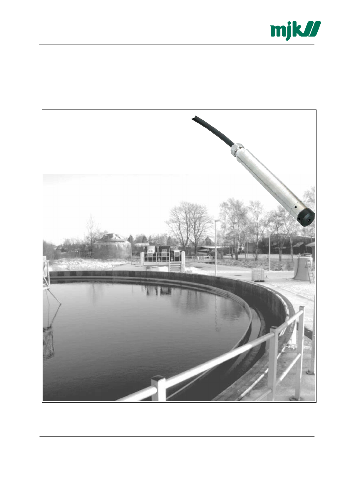
Expert
™ 700
Subme
rsible Hydrostati
c Lev
el Transmitter
s
As our products ar e continuously improved, we reserv e the right to make
Byageren 7
DK-2850 Naerum
Denmark
Tel.:
+45 45 56 06 56
Fax:
+45 45 56 06 46
mjk@mjk.com
w.mjk.com
Page 2
Manual
GB Manual Expert 700 0712
any change in the stated specifications and dimensions without prior notice.
MJK Automation A/S
ww
Contents:
Approval
Introductio
s
n
Product identification
Safet
y instructions
Hazardo
Repai
us areas
r
Mechanical mounting
Electrical mounting
Designatio
n o
f wire
s, cutti
ng & str
ipping t
he cabl
e 5
Designations: 6
Plea
se n
ote t
he f
ollowi
Data Shee
t forExpert
ng installatio
™ 700LevelTra
n instructions
nsmitter
: 6
Dimensions
Accessories
MJK Read Link
Approval
C
E Certificate o
Thi
directiv
theMember State
We decla
Introductio
Tha
transmitte
Expert
s
s produ
e n
re that t
nk you f
r tha
T
M
L
f conformit
ct complie
s wit
o. 89/336/E
s relating t
he produ
n
or choosi
t can fulfi
evel Transmitt
y
h the requirement
EC of 3rd May 1
989
o electromagneti
ct complie
ng Exper
l all you
er i
s suitable for all kinds o
s t
o the values stipulate
T
M
t
L
evel Transmitter.Wehavedone everythingpossibleto makeal
r demands
s concerning electromagneti
, alt
ere
d a
t directiv
c compatib
ility
e n
.
o. 92/31/EEC
d inEN61000-6-1/ to 6-4
.
f levelmeasurements.Itcancontrolandsup
c compatib
ility (
, on the approximatio
EMC
) stipulate
n o
ervisel
d in Council
f the laws o
eve
f
l
evelsin wellsand
tanks-includingaggressive and polluted media.
T
The Expert
the mostbenefitsfromth
Y
ou can always contac
http://
Expert
supplier of hydrostatic l
M
L
evel Transmitt
www.mjk.c
T
M
L
evelT ransmitterisregist
om
er i
s both easy to install and p
T
e Expert
M
L
evelT ransmitt
t your representativ
eredtrademark of MJK.Thank you f
eve
l transmitter
.
e o
r t
he MJK
er right fro
Servic
ut into s
m t
he beginnin
ervice, b
e Hotline for advic
or choosing MJ
ut read thi
s manual firs
g.
e and guidance. Also, tak
K Automatio
t - the
n y
e aloo
n A/S as you
ou w
r
illge
k a
t
t
2
2
2
3
3
3
3
5
7
8
8
8
Produc
Itis very
Check tha
t identification
importantforthe o
t the item(s) delivere
packing:
O
n t
he model Expert 700 transmitters
printedon a label o
n t
he transmitte
verallmeasu
d corresponds t
ringaccuracytha
o theordere
, t
he pressure range
r housing. For all version
As our products ar e continuously improved, we reserv e the right to make
t t
he pressure transmitte
d item(s) b
s togethe
s t
r wit
he pressure range is indicated o
r has t
he corre
y means o
h t
f the information o
he corresponding part number
ct pressure range
n the labelon t
s are
n thelabel.
Byageren 7
DK-2850 Naerum
Denmark
Tel.:
+45 45 56 06 56
Fax:
+45 45 56 06 46
mjk@mjk.com
w.mjk.com
.
he
Page 3
Manual
GB Manual Expert 700 0712
any change in the stated specifications and dimensions without prior notice.
MJK Automation A/S
ww
Safet
y instructions
1:
Rea
d thi
s manual c
2: B
e awa
re o
f the environment o
s
afety regulations
3:
Do not op
datasheet). Instal
housin
Max. suppl
erate th
g material
y voltage i
arefully.
n the installatio
n site.Wearnecessaryprotecti
ve equipmentandfollowallcu
.
e equipment outside the specifiedelectrical, thermal and mechanica
l the device only i
n media f
or which thewettedmaterials
havesufficientdurability.(
)
s 30 VDC
.
l p
arameters (see
Seedatasheetfor
rrent
Hazardo
Expert™ 700 Level
Repai
1:
Repair o
Mechanica
us areas
r
f THEequipmen
l mounting
l Transmitt
t must onl
er is NOT approved forexplosion h
Model 700
1: Mo
unt a suitable h
2:Removethe innerco
ook over t
nicalsl
he desire
eeve fromthecablefittingan
sleeve andfititaroundthecable a
Securethecablefittingbypu
3: Lowe
r t
he pressure transmitter int
Takecareno
4: If t
install a pip
t tohit thebottomhardsinceit maydamaget
he transmitter i
e (mi
s t
n. nomina
llingthecabledownwards
o b
e used in a wetwell or otherlocations wit
l diamete
components.
Cablebracke
t
y be madeb
y MJK o
r b
d measuringlocation. Not
d pul
t thedesiredfixationpoint an
.
o t
he wellpipe
.
he transmitter
r = 25 mm)t
o prote
ct t
he transmitte
azardo
us a
reas.
y a s
ervic
e representative approve
e the weigh
l the cable through t
d pres
s the inne
!
h turbulenc
r fro
m bumpi
d b
t o
f t
he cable
r sleeve int
he oute
.
r part
o place i
. Ope
n t
e or other disturbance
ng into t
he wal
y MJK
.
n the inner
he outerpart.
, it is advisable to
l orother
Protection pipe
I
of t
c
t is v
ery important tha
he pressuretransmitter i
o
vere
d b
y the pipe!
As our products ar e continuously improved, we reserv e the right to make
t minimum 25 mm
s not being
Byageren 7
DK-2850 Naerum
Denmark
Tel.:
+45 45 56 06 56
Fax:
+45 45 56 06 46
mjk@mjk.com
w.mjk.com
Page 4

Manual
GB Manual Expert 700 0712
any change in the stated specifications and dimensions without prior notice.
MJK Automation A/S
ww
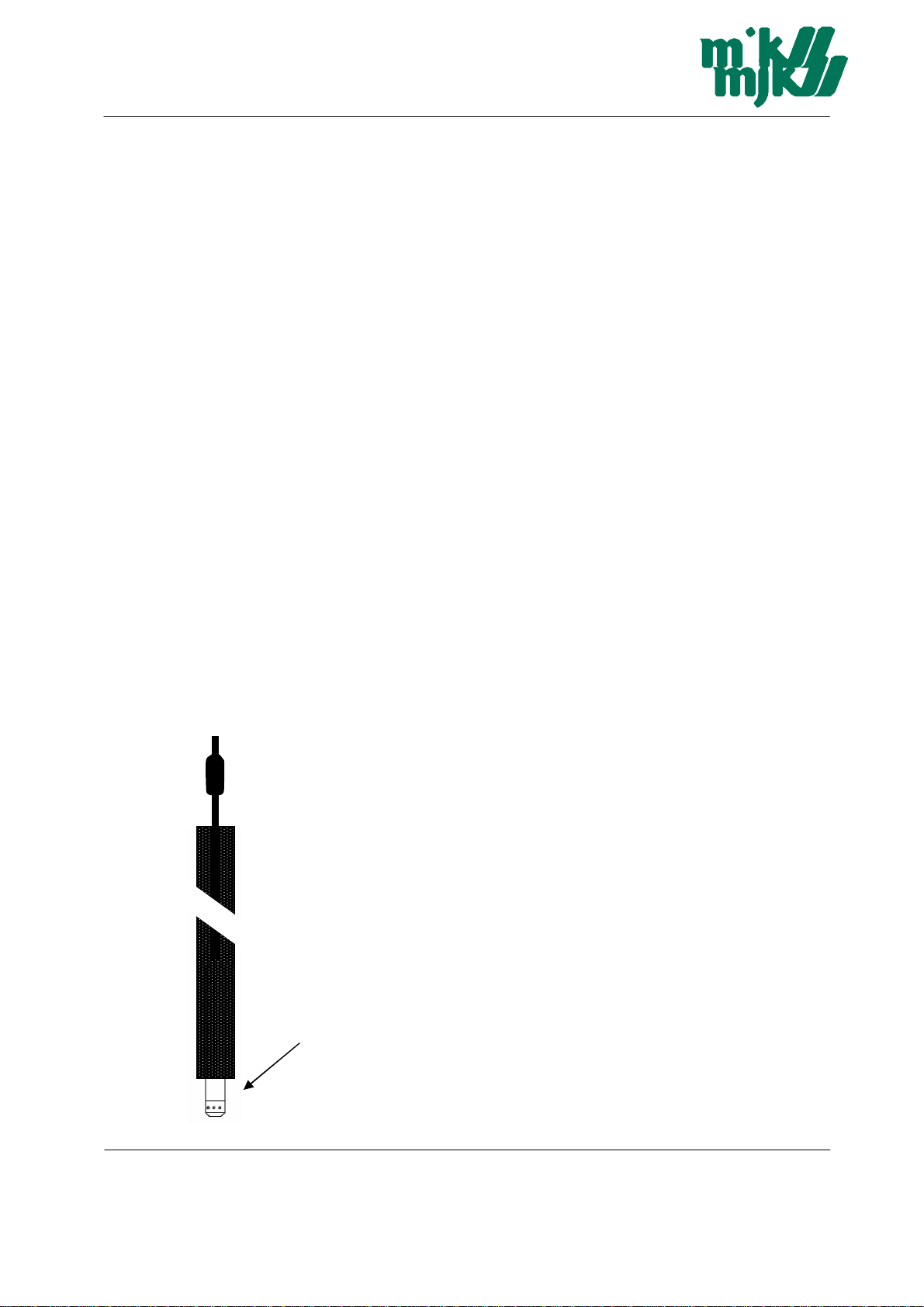
Maintenance
The black cover is pulled off to clean the pressure sensor. The sensor can then be rinsed off with water.
Under no circ umstances must pressure be applied to the delicate pressure sensor membrane, as this can destroy
this elem ent!!
Caution:
The pressure sensor membrane is extremely delicate. The membrane must therefore never be touched!!
Pressure sensor
Protective sensor sleeve
DAMAGE FROM TOUCHING THE MEMBRANE OR HIGH PRESSURE W ATER JETS ON THE MEMBRANE IS
NOT COVERED UNDER WARRANTY!
As our products ar e continuously improved, we reserv e the right to make
Byageren 7
DK-2850 Naerum
Denmark
Tel.:
+45 45 56 06 56
Fax:
+45 45 56 06 46
mjk@mjk.com
w.mjk.com
Page 5

Manual
GB Manual Expert 700 0712
any change in the stated specifications and dimensions without prior notice.
MJK Automation A/S
ww
Electrica
Cable lengt
T
he cable can b
Although t
cable
E
nsurethatn
The length o
the analo
l mounting
h vs. su
he measuringsign
. This is especially important around VFD’s and motor power cables.
f t
g inpu
ppl
y voltag
e lengthened wit
e
h any typ
al i
s generally n
e o
f cableusing connecti
ot sensitiv
e to electrical noise
o moisturecanenterthepressurecompensation tub
he cable i
t o
s only limited b
n t
he MJK 7
y the tot
04, MJ
K 713, PLC etc.(typically 1
al resistance (A) o
0 t
(typically 24 V DC).
Designatio
T
he factory deli
D
o NOT connec
b
e cu
Tak
e care not t
Exampl
T
he nominal resistance f
2x 0,036x 12= 0,86Ωtotheloopresistance.Ifth
b
e approx
Necessary suppl
(A)Tota
t o
ff i
n differe
e:
. 51Ω.
l l
oop resistanc
n o
f wire
s, cutti
vere
d cable has t
t any o
f theprogrammin
nt lengths t
o bloc
k or squ
y voltage in relati
e [Ω]
ng & str
he wire
o p
revent the
eez
e th
or 1 conducto
on t
o t
he total l
ipping t
he cabl
s marked withcolours
g wiresas i
m fro
e a
ir pre
r i
n a transmittercabl
t may damag
m shor
t circuit
ssurecompensat
e analo
oop resistance.
e
e i
g inpu
as t
.
s 0
on bo
x 2
02922
.
, w
e recommendt
e inside the cable
f t
he cable conductor
.
o 100Ω) and the availabl
o t
he table below.
e the transmitter
ion tub
. The programmingwire
e
,036Ω/m. A standard 1
t has a
n impedance of 50Ω
he use of a screene
s + the inp
ut impedance
e suppl
2 m cable will th
, t
he totalresistanc
y voltage
s should
erefore a
d
of
dd
e will
Accordin
g to t
he diagra
m above, approx
As our products ar e continuously improved, we reserv e the right to make
. 1
2 V D
C w
illbe sufficien
(B)Supply voltage [V DC
t
]
Byageren 7
DK-2850 Naerum
Denmark
Tel.:
+45 45 56 06 56
Fax:
+45 45 56 06 46
mjk@mjk.com
w.mjk.com
Page 6

Manual
GB Manual Expert 700 0712
any change in the stated specifications and dimensions without prior notice.
MJK Automation A/S
ww
Designations:
Black Vcc + (24VDC) Output 4-20mA
White GND
Blue RS 485A
Yellow RS 485 B
Red NC
Air pressurecompensation tub
Screen
e
Cutted andstripped
Factory delivery
.
Plea
se n
ote t
he f
ollowi
1.Followthe installat
2. Install accordin
g to t
ng installatio
ionands
afety instructionscontainedi
he manufacturer’
n instructions
:
n t
he Operation Instructions.
s instructionsand other vali
d standard
s an
3.Donot operatethesensor outsidethespecifiedelectrical,thermal and mechanica
4. Install the device only i
Be aware about the environment on the installation site. Use necessar
n media f
or which t
he wettedmaterials have sufficien
y p
rotection equipment an
t durability
regulati ons.
As our products ar e continuously improved, we reserv e the right to make
d guidelines
l p
arameters.
.
.
d f
ollow all safety
Byageren 7
DK-2850 Naerum
Denmark
Tel.:
+45 45 56 06 56
Fax:
+45 45 56 06 46
mjk@mjk.com
w.mjk.com
Page 7

Manual
GB Manual Expert 700 0712
any change in the stated specifications and dimensions without prior notice.
MJK Automation A/S
ww
Data Shee
t forExpert™ 700LevelTra
nsmitter
The MJK Expert™ 700 Level Transmitter has a small external diameter
of 16 mm - and is made of 316L stainless steel.
The transmitter is designed for measuring levels in water wells.
The MJK Expert™ 700 is an accurate 2-wire transmitter with a
piezoresistive measuring system with direct air pressure and
temperature compensation and built-in surge protection.
Specifications
MJK Expert™ 1400 Hydrostatic Level Transmitter
As our products ar e continuously improved, we reserv e the right to make
Byageren 7
DK-2850 Naerum
Denmark
Tel.:
+45 45 56 06 56
Fax:
+45 45 56 06 46
mjk@mjk.com
w.mjk.com
Page 8

Manual
GB Manual Expert 700 0712
any change in the stated specifications and dimensions without prior notice.
MJK Automation A/S
ww
Order Numbe
Dimensions
rs
Accessories
Cable bracket
Each Expert™ 700 Level Transmitter also integrates a digital interface (RS485 half duplex) which the user
can make use of. The transmitter is being connected via a converter RS232-RS485 (Item No. 203992) to
a PC or Laptop. The program offered is:
MJK Read Link
•
Information (pressure- and temperature range, version of software etc.)
•
Indication of actual pressure value
•
Selection of the units
•
Setting of a new zero and gain for the transmitter
•
Reprogramming of the analog output (i.e. different unit, other pressure range)
•
Setting of the instrument address (for Bus-operation)
•
Low-Pass Filter adjusting possibility
•
Data collection with graphs
•
Fast read-out and viewing of the pressure signals in a graph
•
Documentation of dynamic measurements
•
Up to 16 transmitters on one serial connection (Bus-operation)
As our products ar e continuously improved, we reserv e the right to make
Byageren 7
DK-2850 Naerum
Denmark
Tel.:
+45 45 56 06 56
Fax:
+45 45 56 06 46
mjk@mjk.com
w.mjk.com
 Loading...