

Page 1
Manual
Expert™ 1400 / Expert™ 3400
Submersible Hydrostatic Level Transmitters
ll 2G
EEx ia llC T6
Manual Expert 1400/3400 GB 0704
As our products are continuously improved, we reserve the right to make
any change in the stated specifications and dimensions without prior notice.
MJK Automation A/S
Byageren 7
DK-2850 Naerum
Denmark
Tel.: +45 45 56 06 56
Fax: +45 45 56 06 46
mjk@mjk.com
www.mjk.com
Page 2

Manual
Approvals
CE Certificate of conformity
This product complies with the requirements concerning electromagnetic compatibility (EMC) stipulated in Council
directive no. 89/336/EEC of 3rd May 1989, altered at directive no. 92/31/EEC, on the approximation of the laws of the
Member States relating to electromagnetic compatibility.
We declare that the product complies to the values stipulated in EN50014:1997, EN50020:2002,
EN61000-6-3/-4:2001 and EN61000-6-1/-2:1999.
Manual Expert 1400/3400 GB 0704
2
MJK Automation A/S
Byageren 7
DK-2850 Naerum
Denmark
Tel.: +45 45 56 06 56
Fax: +45 45 56 06 46
mjk@mjk.com
www.mjk.com
Page 3

Manual
Introduction 4
Product identification
Safety instructions 4
Hazardous areas 4
Repair 4
Mechanical mounting 5
Model 1400 5
Model 3400 5
Model 3400 with thread top 5
Electrical mounting 6
Cable length vs. supply voltage 6
Designation of wires, cutting & stripping the cable 6
Explosion hazardous zone 7
Isolator 7
Zener barrier
Appendices 8
Mechanical dimensions 8
Demands for cables in explosive areas 8
Safety Instructions 9
Data Sheet for Expert™ 1400 Level Transmitter 12
Data Sheet for Expert™ 3400 Level Transmitter 13
4
7
Manual Expert 1400/3400 GB 0704
3
MJK Automation A/S
Byageren 7
DK-2850 Naerum
Denmark
Tel.: +45 45 56 06 56
Fax: +45 45 56 06 46
mjk@mjk.com
www.mjk.com
Page 4
Manual
Introduction
Thank you for choosing ExpertTM Level Transmitter.
We have done everything possible to make a level
transmitter that can fulfil all your demands.
ExpertTM Level Transmitter is suitable for all kinds of level
measurements. It can control and supervise levels in wells
and tanks - including aggressive and polluted media.
The ExpertTM Level Transmitter is both easy to install and
put into service, but read this manual first - then you will
get the most benefits from the ExpertTM Level Transmitter
right from the beginning.
You can always contact your representative or the MJK
Service Hotline for advice and guidance. Also, take a
look at http://www.mjk.com
ExpertTM Level Transmitter is registered trademark of MJK.
Thank you for choosing MJK Automation A/S as your
supplier of hydrostatic level transmitter.
Product identification
It is very important for the overall measuring accuracy that
the pressure transmitter has the correct pressure range.
Check that the item(s) delivered corresponds to the
ordered item (s) by means of the information on the label
on the packing:
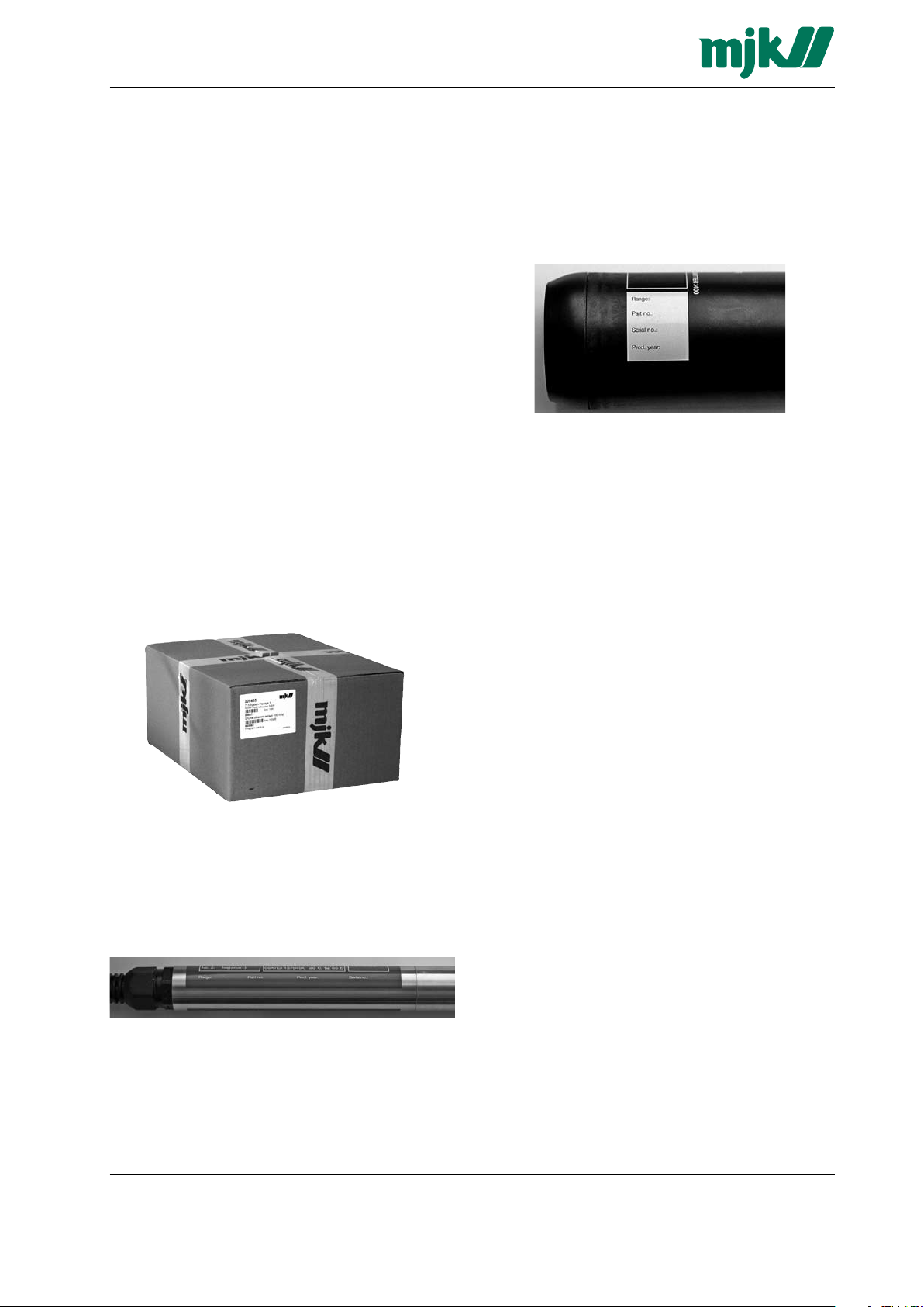
On the model 3400 transmitters, the pressure ranges together with the corresponding part numbers are printed
on a label on the transmitter housing.
For all versions the pressure range is indicated on the
label.
3400 transmitter
Safety instructions
1: Read this manual carefully.
2: Be aware of the environment on the installation site.
Wear necessary protective equipment and follow all current
safety regulations.
3: Do not operate the equipment outside the specified
electrical, thermal and mechanical parameters (see
datasheet). Install the device only in media for which the
wetted materials have sufficient durability. (See datasheet
for housing material)
Max. supply voltage is 30 VDC.
4: Do not connect or use any programming interface/
equipment while the transmitter is located in an explosion
hazardous environment.
On the model 1400 transmitters, the pressure ranges together with the corresponding part numbers are printed
on a label on the transmitter housing.
For all versions the pressure range is indicated on the
label.
1400 transmit ter
Manual Expert 1400/3400 GB 0704
Hazardous areas
1: All current local and national standards, regulations
regarding installation and use of Ex or hazardous zone
approved equipment, certifications and safety instructions
for Ex equipment that have been used together with the
installation of the Expert 1400 or 3400 level transmitter
must be strictly observed.
2: The use of an approved zener barrier or isolator is
mandatory when installing Expert™ Level Transmitter
1400 and 3400 in explosion hazardous areas.
Repair
1: Repair of EX approved equipment must only be made
by MJK or by a service representative approved by MJK.
4
MJK Automation A/S
Byageren 7
DK-2850 Naerum
Denmark
Tel.: +45 45 56 06 56
Fax: +45 45 56 06 46
mjk@mjk.com
www.mjk.com
Page 5
Manual
Mechanical mounting
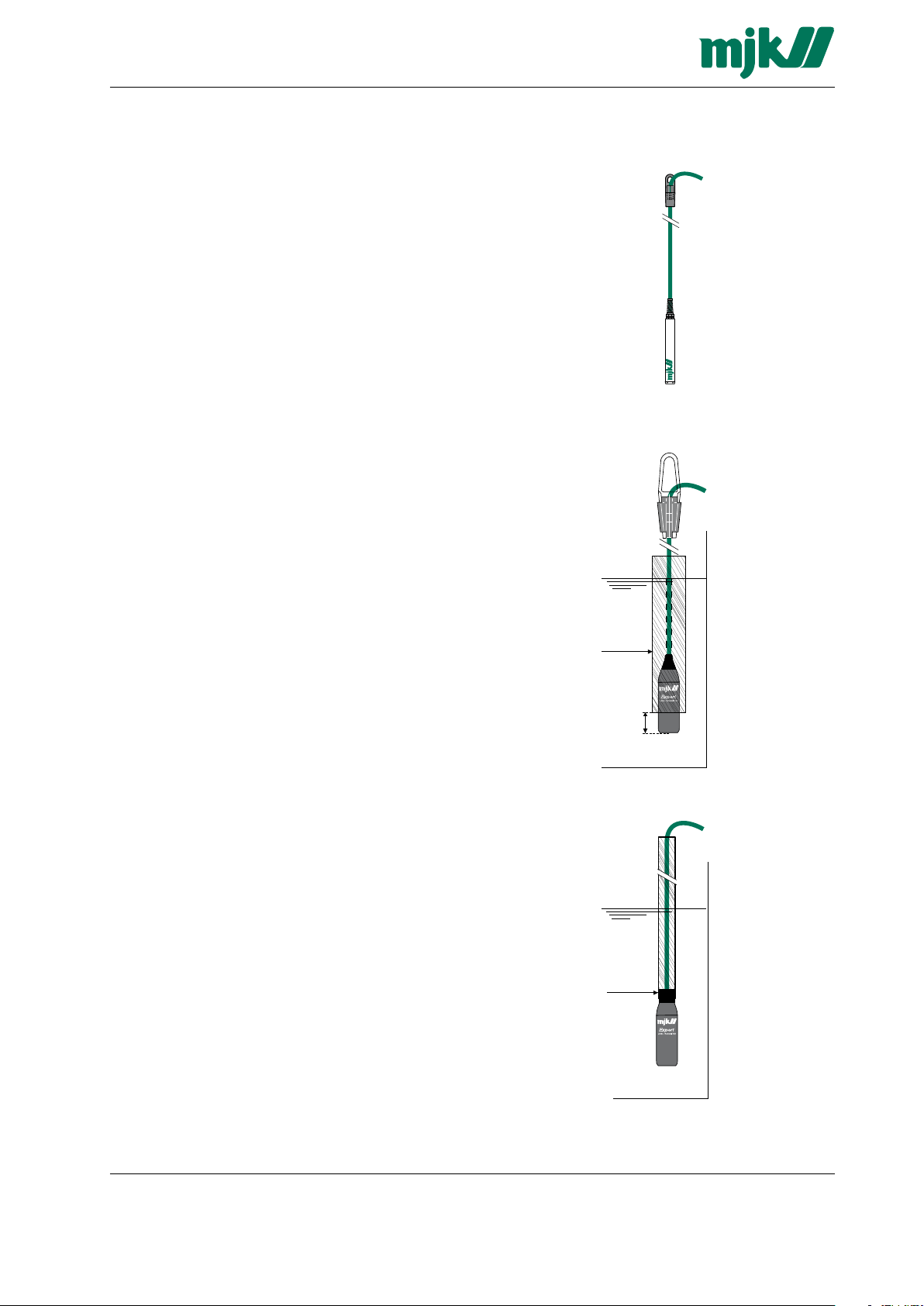
Model 1400
1: Mount a suitable hook over the desired measuring
location. Note the weight of the cable.
2: Remove the inner conical sleeve from the cable fitting
and pull the cable through the outer part. Open the inner
sleeve and fit it around the cable at the desired fixation
point and press the inner sleeve into place in the outer
part. Secure the cable fitting by pulling the
cable downwards.
3: Lower the pressure transmitter into the wellpipe.
Take care not to hit the bottom hard since it may damage
the transmitter!
Model 3400
1: Mount a suitable hook over the desired measuring
location. Note the weight of the cable.
2: Mount the cable fitting onto the cable. Open the fitting
by sliding the two plastic jaws upwards, place the cable
between the jaws and slide the jaws downwards until the
cable locks. Secure the cable fitting by pulling the
cable downwards.
3: Lower the pressure transmitter into the liquid.
Take care not to hit the bottom hard since it may damage
the transmitter!
4: If the transmitter is to be used in a wetwell or other
locations with turbulence or other disturbance, it is advisable to install a pipe (min. nominal diameter = 75 mm)
to protect the transmitter from bumping into the wall or
other components.
It is very important that minimum 25 mm of the pressure
transmitter is not being covered by the pipe!
Cable
bracket
Model 1400
Cable
bracket
Protective pipe.
Protective pipe.
Min. nominal
diamete r = 75mm
Model 3400
Min. 25-50 mm
Model 3400 with thread top
1: Mount the pressure transmitter onto a 1 in pipe
(1” ISO thread) and mount the pipe firmly at the desired
measuring location.
2: Lower the pressure transmitter into the liquid.
Take care not to hit the bottom hard since it may damage
the transmitter!
Manual Expert 1400/3400 GB 0704
1" ISO thread
Model 3400
5
MJK Automation A/S
Byageren 7
DK-2850 Naerum
Denmark
Tel.: +45 45 56 06 56
Fax: +45 45 56 06 46
mjk@mjk.com
www.mjk.com
Page 6

Manual
Electrical mounting
Cable length vs. supply voltage
The cable can be lengthened with any type of cable
using connection box 202922. Although the measuring
signal is not sensitive to electrical noise, we recommend
the use of a screened cable.
Ensure that no moisture can enter the pressure compensation tube inside the cable.
The length of the cable is only limited by the total resistance (A) of the cable conductors + the input impedance
of the analog input on the MJK 704, MJK 713, PLC etc.
(typically 10 to 100 Ω) and the available supply voltage
(B) (typically 24 V DC).
Example:
The nominal resistance for 1 conductor in a transmitter
cable is 0,036 Ω /m. A standard 12 m cable will therefore
add 2 x 0,036 x 12 = 0,86 Ω to the loop resistance. If the
analog input has an impedance of 50 Ω., the total
resistance will be approx. 51 Ω.
Necessary supply voltage in relation to the total loop resistance.
(A) Total loop resistance [ Ω]
Designation of wires, cutting & stripping the cable
The factory delivered cable has the wires marked with
the numbers 1 - 2 - 3 as to the table to the right. If the
cable needs to be cutted and stripped, the shield should
be connected as the no. 3 wire.
Do NOT connect any of the colored programming wires
as it may damage the transmitter. The programming
wires should be cut off in different lengths to prevent
them from short circuit.
Take care not to block or squeeze the air pressure
compensation tube ➄.
Designations:
1: Positive (+) wire, red
2: Negative (-) wire, brown
3: Shield
(NOT signal ground!)
4: Moisture filter for compensation tube
5: Air pressure
compensation tube
6: Programming wires
➀
➁
➂
➃
➁
➀
➄
➃
➅
➂
(B) Supply voltage [ V DC]
According to the diagram above, approx. 12 V DC will
be sufficient.
Factory delive ry
Do not connect a programming unit to the transmitter
or make any attemt to program the tranmitter while the
transmitter is located in an explosion hazardous zone!
Cutted and
stripped
Manual Expert 1400/3400 GB 0704
6
MJK Automation A/S
Byageren 7
DK-2850 Naerum
Denmark
Tel.: +45 45 56 06 56
Fax: +45 45 56 06 46
mjk@mjk.com
www.mjk.com
Page 7

Manual
Hazardous area Safe area
Isolator
202993
1 +
2 -
POWER SUPPLY 515
200100
24VDC
7
24VDC
+
6
230VAC
N
3
230VAC
L
1
Pasiv
mA input
AI
+
AI
-
230 VAC
KFD0-CS-Ex1.50P isolator
+
Wire 1
Red
Wire 2
Brown
shield
Wire 3
black
11 (+)
12 (-)
Safe areaHazardous area
POWER SUPPLY 515
200100
24VDC
-
7
24VDC
+
6
230VAC
N
3
230VAC
L
1
Pasiv
mA input
AI
-
AI
+
230 VAC
+
Wire 1
Red
Wire 2
Brown
shield
Wire 3
black
1
3
2
8
Zener barriere
202995
4
7
Z788 Zener Barrier
Explosion hazardous zone
The insulation between the intrinsic safe circuit and the enclosure withstands 500 VAC.
Isolator
The KFD0-CS-Ex1.50P isolator (MJK part no.: 202993) which supplies the pressure transmitter through a galvanic separator so neither current nor voltage exceeds the specified limits.
Zener barrier
The Z788 Zener Barrier ( MJK part no. 202995) has a safety fuse which will blow if the current exceeds the limit.
The voltage protection in the Zener barrier contains a number of zener diodes, which are connected from each signal
cable to ground.
Manual Expert 1400/3400 GB 0704
MJK Automation A/S
7
Byageren 7
DK-2850 Naerum
Denmark
Tel.: +45 45 56 06 56
Fax: +45 45 56 06 46
mjk@mjk.com
www.mjk.com
Page 8

Manual
135
135
152 65
Appendices
Mechanical dimensions
MJK model 1400
Level transmitter
MJK model 3400
Level transmitter
Cable bracket
Cable bracket
Demands for cables in explosive areas
Using the the KFD0-CS-Ex1.50P isolator (MJK order
no.: 202993) the max cable length can be calculated.
The Cmax and Lmax for the isolator in explosion group
IIC are: Cmax : 2,41 μF, Lmax : 4 mH. The capacity of
MJK cable type 691005 or 691014 < 800 pF/m and
the inductance is < 1,5 μH/m and the capacity and the
inductance of the Expert Level Transmitter is Ci = 3,5 nF
Li = 7 μH. Cable length based on the capacity:
Max.cable length = (Cmax-Ci)/Ccable = 129 m
Cable length based of the inductance:
Max. cable length = (Lmax-Li)/Lcable = 2862 m
In this case the capacitance sets the limit of the cable
length to 129 m. If another approved isolator or another
cable is used the max. cable length must be recalculated.
Using The Z788 Zener Barrier (MJK Order no. 202995)
the max cable length can be calculated. The Cmax and
Lmax for the zener barrier in explosion group IIC are:
Cmax : 83 nF, Lmax : 3,05 mH. The capacity of MJK
cable type 691014 is < 800 pF/m and the inductance is
< 1,5 μH/m and the capacity and the inductance of the
Expert Level Transmitter is Ci = 3,5 nF Li = 7 μH.
Cable length based on the capacity:
Max. cable length = (Cmax-Ci)/Ccable = 99 m
Cable length based on the inductance:
Max. cable length = (Lmax-Li)/Lcable = 2,0 km
In this case the capacitance sets the limit of the cable
length to 99 m. If another Atex-approved isolator or
another cable is used the max. cable length must
be recalulated.
Manual Expert 1400/3400 GB 0704
8
MJK Automation A/S
Byageren 7
DK-2850 Naerum
Denmark
Tel.: +45 45 56 06 56
Fax: +45 45 56 06 46
mjk@mjk.com
www.mjk.com
Page 9
Manual
Safety Instructions
for electrical apparatus for explosion-hazadous areas
Designation according to Directive 94/9/EC
- Equipment group II
- Equipment Category: sensor and housing category 2
- For explosive mixtures of air and combustible gases vapour or mists
Area of application:
For explosive mixtures of air and combustible gases, vapour or mists:
Equipment category Explosive gas-air mixtures (G)
Category 1 Zone 0, 1 or 2
0539
2GII
Category 2 Zone 1 or 2
Category 3 Zone 2
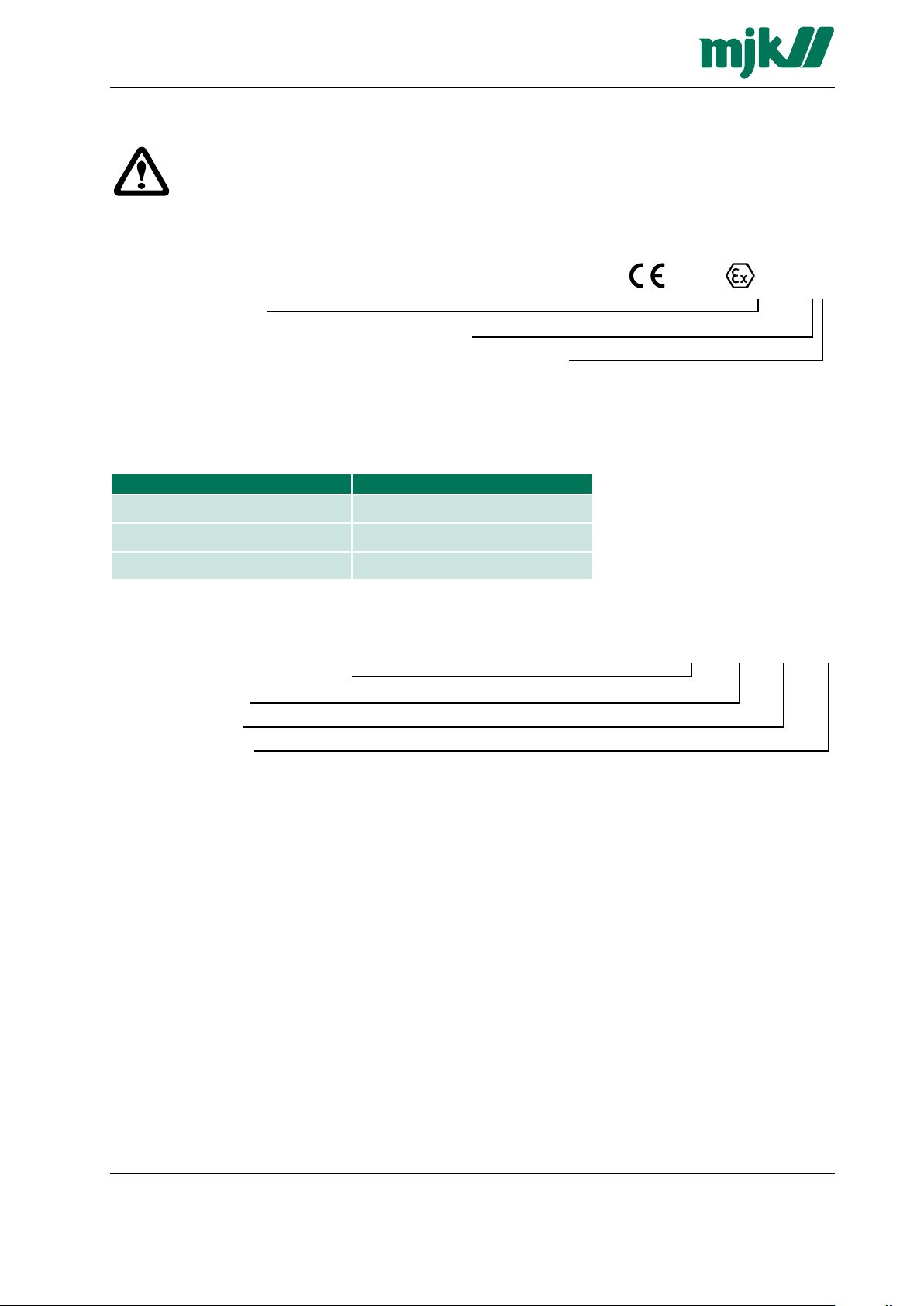
Designation of explosion protection: EEx ia IIC T6
- Electrical apparatus with explosion
- Protection to European standard
- Type of protection
- Apparatus group
- Temperature class
Marking of Expert transmitter type 1400/3400 for Ex environment
II 2 G EEx Ia IIC T6 means:
II: Equipment group: Surface industry
2: Category: Category 2 (Zone 1 and 2)
G: Explosive atmosphere: Gas
E: European Standards.
Ex: Equipment for explosive atmospheres.
Ia: Ex Protection principle: Intrinsically safety.
IIC: Gas groups: Acetylene & hydrogen.
T6: Temperature class: 85°C surface temperature
Manual Expert 1400/3400 GB 0704
9
MJK Automation A/S
Byageren 7
DK-2850 Naerum
Denmark
Tel.: +45 45 56 06 56
Fax: +45 45 56 06 46
mjk@mjk.com
www.mjk.com
Page 10

Manual
Non hazardous area
Explosive hazardous area
Zone 1
+ Red
- Brown
Shield
Black
Type 3400 Type 1400
+ Red
- Brown
Shield
Black
Type of protection Electrical data Ambient temperatur
II 2G EEx ia IIC T6 IP 65
Ui: 30 V DC
Ii: 101 mA
Pi: 750 mW
Ci: 3,5 nF+800 pF/m*cable length
Li: 7 μH+1.5 μH/m*cable length
-20 °C < Ta < 40 °C
Using the KFD0-CS-Ex1.50P isolator (MJK order no.:
202993) the max. cable length is 129 m.
Using The Z788 Zener Barrier (MJK Order no. 202995)
the max. cable length is 99 m.
Alternatively other cable types with equivalent specifications may be used. If a cable is used with other electrical
specifications or other approved isolators and zener
barrier are used, the cable length must be recalculated.
Manual Expert 1400/3400 GB 0704
10
MJK Automation A/S
Byageren 7
DK-2850 Naerum
Denmark
Tel.: +45 45 56 06 56
Fax: +45 45 56 06 46
mjk@mjk.com
www.mjk.com
Page 11

Manual
Please note the following installation instructions:
1. Follow the installation and safety instructions contained
in the Operation Instructions.
2. Install according to the manufacturer’s instructions
and other valid standards and guidelines.
3. Do not operate the sensor outside the specified electrical,
thermal and mechanical parameters.
4. Install the device only in media for which the wetted
materials have sufficient durability.
5. Expert transmitter type 1400/3400 hydrostatics level
transmitter may not be used in explosive areas without
use of correct Isolator or Zener Barrier.
6. The approved Expert Level Transmitter type
1400/3400 does not need to be separately connected
with, structural parts or piping which are connected to
the equipotential bonding system.
7. The ambient temperature range of the Expert Level
Transmitter type 1400/3400 (-20 °C< Ta<+40 °C.)
Be aware about the environment on the installation site.
Use necessary protection equipment and follow all
safety regulations.
Manual Expert 1400/3400 GB 0704
11
MJK Automation A/S
Byageren 7
DK-2850 Naerum
Denmark
Tel.: +45 45 56 06 56
Fax: +45 45 56 06 46
mjk@mjk.com
www.mjk.com
Page 12

Manual
Dia. 24 mm
73 mm
152 mm 65 mm
Dia. 22 mm
Data Sheet for
Exper t™ 1400 Level
Transmitter
Specifications
MJK Expert™ 1400 Level Transmitter has
about the same specifications as the 7070
model. In addition it has a ceramic, capacitive measuring system with a much higher
accuracy. Furthermore, Expert™ 1400 is
approved for use in explosion hazardous
areas: ATEX Ex ia IIC T6.
Model 1400 is very useful for level measurements in for example ground water bore
holes and in-fill sites, where explosion proof
transmitters are required.
MJK Expert™ 1400 Hydrostatic Level Transmitter
Nominal measuring range 0 - 0,3 m 0 - 1 m 0 - 3 m 0 - 5 m 0 - 10 m 0 - 30 m 0 - 100 m 0 - 300 m
Measuring principle Ceramic capacitive, relative pressure
Min. programmable range 0 - 0,3 m 0 - 0,3 m 0 - 1 m 0 - 3 m 0 - 3 m 0 - 10 m 0 - 30 m 0 - 90 m
Max. programmable range 0 - 1 m 0 - 1 m 0 - 3 m 0 - 10 m 0 - 10 m 0 - 30 m 0 - 100 m 0 - 300 m
Max. overpressure 4 bar 4 bar 6 bar 10 bar 10 bar 18 bar 40 bar 40 bar
Temperature range -20 °C to 40 °C
Temp. deviation, 0 point Better than ± 0.02 % / °C
Temperature deviation, FS Better than ± 0.01 % / °C
Linearity / Stability Better than ± 0.2 % FS / ± 0.2 % FS
Measurement accuracy
Long time stability Better than ± 0.1 % FS per year
Materials Housing: stainless steel (AISI 316 L), diaphragm: 96,6 % Al2O3/Cell packing: Viton
Supply voltage 10 - 30 V DC (12 - 30 V DC for cable lengths above 100 m)
Output signal 2-wire 4 - 20 mA (passive transmitter)
Cable 2 × 0,5 mm2 (pressure) + 5 x 0,15 mm2 (data), shielded, PUR insulation
Cable length 12 m 12 m 12 m 12 m 12 m 35 m 110 m 320 m
Enclosure IP 68, withstands a static pressure equal to max. overpressure.
Approvals
➀
Can be delivered with other cable lengths on request.
Better than ± 0.1 % FS @ +10 to 30 °C
Better than ± 0.2 % FS @ full temperature range
®
ATEX: II 2G EEx ia IIC T5/T6 and CE: EN61000-6-3/-4:2001, EN61000-6-1/-2:1999,
EN50014:1997 E, EN50020:2002
Order Numbers
Dimensions and
Accessories
Manual Expert 1400/3400 GB 0704
Order Numbers
203911 Expert™ 1400, range 0 - 0,3 mWG 203916 Expert™ 1400, range 0 - 30 mWG
203912
203913
203914
203915
Expert™ 1400, range 0 - 1 mWG 203917 Expert™ 1400, range 0 - 100 mWG
Expert™ 1400, range 0 - 3 mWG 203918 Expert™ 1400, range 0 - 300 mWG
Expert™ 1400, range 0 - 5 mWG 202925 Expert™ 1400, special meas. range
Expert™ 1400, range 0 - 10 mWG
MJK Expert™ 1400
Level Transmitter
All 1400 transmitters are Atex approved.
Cable bracket for MJK Expert™ 1400
Level Transmitter
(1 pc. is delivered with each transmitter)
MJK Automation A/S
12
Byageren 7
DK-2850 Naerum
Denmark
Tel.: +45 45 56 06 56
Fax: +45 45 56 06 46
mjk@mjk.com
www.mjk.com
Page 13

Manual
60 mm
236 mm
135 mm
32 mm
Dia. 50 mm
1” NPT
Dia. 50 mm
135 mm
36 mm
Data Sheet for
Exper t™ 3400 Level
Transmitter
Specifications
MJK Expert™ 3400 Level Transmitter is
designed for use in waterworks, sewage
treatment plants and industrial applications
where accurate and long term stable level
measuring is required. It is very robust and
designed for applications in rough environments with aggressive chemicals and
aggressive fluids.
A major design feature is the programming
facility. With a standard USB interface and
a laptop computer, the servicing transmitter can be programmed on-the-fly to the
required measuring range.
MJK Expert™ 3400 Hydrostatic Level Transmitter
Nominal measuring range 0 - 0,3 m 0 - 1 m 0 - 3 m 0 - 5 m 0 - 10 m 0 - 30 m 0 - 100 m 0 - 300 m
Measuring principle Ceramic capacitive, relative pressure
Min. programmable range 0 - 0,3 m 0 - 0,3 m 0 - 1 m 0 - 3 m 0 - 3 m 0 - 10 m 0 - 30 m 0 - 90 m
Max. programmable range 0 - 1 m 0 - 1 m 0 - 3 m 0 - 10 m 0 - 10 m 0 - 30 m 0 - 100 m 0 - 300 m
Max. overpressure 4 bar 4 bar 6 bar 10 bar 10 bar 18 bar 40 bar 40 bar
Temperature range -20 °C to 40 °C
Temp. deviation, zero oint Better than ± 0.02 % / °C
Temperature deviation, FS Better than ± 0.01 % / °C
Linearity / Stability Better than ± 0.2 % FS / ± 0.2 % FS
Measurement accuracy Better than ± 0.1 % FS @ +10 to 30 °C. Better than ± 0.2 % FS @ full temperature range
Long time stability Better than ± 0.1 % FS per year
Materials Housing: stainless steel (AISI 316 L), diaphragm: 96,6 % Al2O3/Cell packing: Viton
Supply voltage 10 - 30 V DC (12 - 30 V DC for cable lengths above 110 m)
Output signal 2-wire 4 - 20 mA (passive transmitter)
Cable 2 × 0,5 mm2 (pressure) + 5 x 0,15 mm2 (data), shielded, PUR insulation
Cable length 12 m 12 m 12 m 12 m 12 m 35 m 110 m 320 m
Enclosure IP 68, withstands a static pressure equal to max. overpressure.
Approvals
➀
Can be delivered with other cable lengths on request.
ATEX: II 2G EEx ia IIC T5/T6, CE: EN61000-6-3/-4:2001, EN61000-6-1/-2:1999,
EN50014:1997 E, EN50020:2002
®
Order numbers
Dimensions and
Accessories
Manual Expert 1400/3400 GB 0704
Order Numbers
203951 Expert™ 3400, range 0 - 0.3 mWG 203957 Expert™ 3400, range 0 - 100 mWG
203952
203953
209954
203955
203956
Expert™ 3400, range 0 - 1 mWG 203958 Expert™ 3400, range 0 - 300 mWG
Expert™ 3400, range 0 - 3 mWG 203961 Expert™ 3400, range 0 - 0.3 m 1" RG top
Expert™ 3400, range 0 - 5 mWG 203962 Expert™ 3400, range 0 - 1 m 1" RG top
Expert™ 3400, range 0 - 10 mWG 203963 Expert™ 3400, range 0 - 3 m 1" RG top
Expert™ 3400, range 0 - 30 mWG 202925 Expert™ 3400 w/ special meas. range
MJK Expert™ 3400
Level Transmitter
Cable bracket for MJK model 3400
(1 pc. is delivered with each transmitter)
MJK Automation A/S
13
Byageren 7
DK-2850 Naerum
Denmark
Tel.: +45 45 56 06 56
Fax: +45 45 56 06 46
mjk@mjk.com
www.mjk.com
Page 14

Manual
This page intentionally left blank.
Manual Expert 1400/3400 GB 0704
14
MJK Automation A/S
Byageren 7
DK-2850 Naerum
Denmark
Tel.: +45 45 56 06 56
Fax: +45 45 56 06 46
mjk@mjk.com
www.mjk.com
Page 15

Manual
This page intentionally left blank.
Manual Expert 1400/3400 GB 0704
15
MJK Automation A/S
Byageren 7
DK-2850 Naerum
Denmark
Tel.: +45 45 56 06 56
Fax: +45 45 56 06 46
mjk@mjk.com
www.mjk.com
Page 16

Manual
Manual Expert 1400/3400 GB 0704
16
MJK Automation A/S
Byageren 7
DK-2850 Naerum
Denmark
Tel.: +45 45 56 06 56
Fax: +45 45 56 06 46
mjk@mjk.com
www.mjk.com
 Loading...