

Page 1

Installation and Operating Instruc-
tions for Electric heater-circulator
unit EPR
Page 2
Instruction manual Laing Electric heater circulator unit
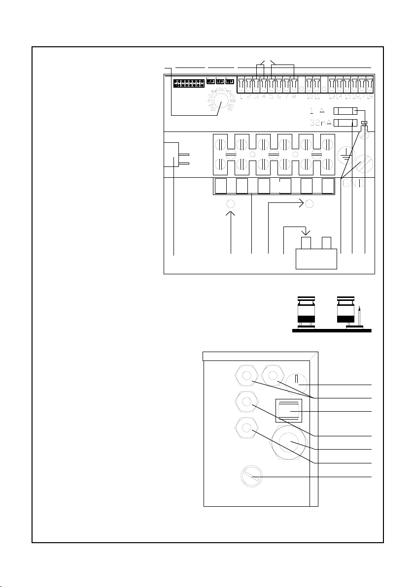
A Terminal strip for Mains
connection
E Ground terminal
F Fuse for pump
H Main switch
I Jumper wires for remote
control input and pump
module input
J Jumper 1 to 8
K Constant temperature
control
L LEDs
M Mounting screws for prin-
ted circuit board (behind
terminal bracket)
N Cable entry for Mains
connection
R Cable entry for control
and circulator
S Safety temperature limiter
U Fuse for control
V Terminals
Z Reset knob for safety
temperature limiter
S J L V
I
L1 L2 L3 N N N
H M A M T E U F
Jumperposition
closed open
Terminal usage
1,2 Remote control for heating
elements 2 and 3
3,4 Input from pump module
5,6 Remote control input
7,8 Remote control input
10,11 Potential free output for remo-
te trouble indicator
13,14 Power supply for daughter
board EPRBW
15,16 Power supply for circulator
17,18 used only for FP 5000 ER
models
See next to last page for jumper positions and error indicators.
2
K
R
H
R
N
R
Z
www.lainginc.com
Page 3

Instruction manual Laing Electric heater circulator unit
Contents
Applications ............................................................................................................... 5
Design of the EPR model .......................................................................................... 5
Technical Data ........................................................................................................... 6
Dimensional Drawing................................................................................................. 7
Performance Curve ................................................................................................... 7
Models Available ........................................................................................................ 8
Mounting .................................................................................................................... 9
Connection to the feed and return line ...................................................................... 9
Electrical Connection ............................................................................................... 10
Power Supply .......................................................................................................... 10
400V N3 Electrical Diagram .................................................................................... 10
230V N1 Electrical Diagram .....................................................................................
230V N3 Electrical Diagram .....................................................................................
The integrated control.............................................................................................. 12
Schematics of the integrated control ....................................................................... 12
Design of the Main Printed Circuit Board ................................................................ 13
Main switch .............................................................................................................. 14
Fuses ....................................................................................................................... 14
Constant temperature control .................................................................................. 14
Overheating Protection ............................................................................................ 14
Program selection for the switching sequence of the heating elements ................. 15
Pump shut-off ......................................................................................................... 17
Deactivating heating elements ................................................................................ 17
Remote control of the second and third heating element ........................................ 17
Control input ............................................................................................................ 18
Room temperature guided control ........................................................................... 18
Outside temperature guided control ........................................................................ 20
Safety temperature limiter ....................................................................................... 20
Electronic means to prevent dry running ................................................................. 21
Circulator operation control ..................................................................................... 21
Malfunction detector ................................................................................................ 22
Attachment of the sensor for the remote control ..................................................... 23
Indirect domestic hot water heating with the Electric heater-circulator EPR ........... 24
Hydraulic connection of the EPR for domestic hot water heating............................ 25
Electrical connection of the EPR for domestic hot water heating ............................ 26
Control method 1 ..................................................................................................... 26
Control method 2 ..................................................................................................... 27
Operation of heating elements with a load shedding device ................................... 28
Filling of the system ................................................................................................. 30
Pressure and leak tests ........................................................................................... 30
Starting operation .................................................................................................... 30
Replacement of the circulation pump ...................................................................... 31
Replacement of the safety temperature limiter STBR ............................................. 31
Replacement of the main circuit board EPRH ......................................................... 32
Important Notices .................................................................................................... 32
Important Notice: How to avoid overheating............................................................ 32
Important Notice: In the event of safety temperature limiter failure ......................... 33
Important Notice: For proper connection to a oor heating system ......................... 33
Factory settings ....................................................................................................... 33
11
11
www.lainginc.com
3
Page 4
Instruction manual Laing Electric heater circulator unit
Applications
Electric heater circulator units Model EPR can be applied in all cases where
electric heating has to be installed in a small space to heat an apartment or
a single or multiple family house.
This applies to direct electrical heating as well as for electrical heating with
a heat storage.
A further application exists in connection with room additions where the
electric heating can supplement the existing hydronic heating.
The Electric heater-circulator is also very well suited to heat domestic
hot water. The application for heating of domestic hot water is described in
“Indirect domestic hot water heating - Application”.
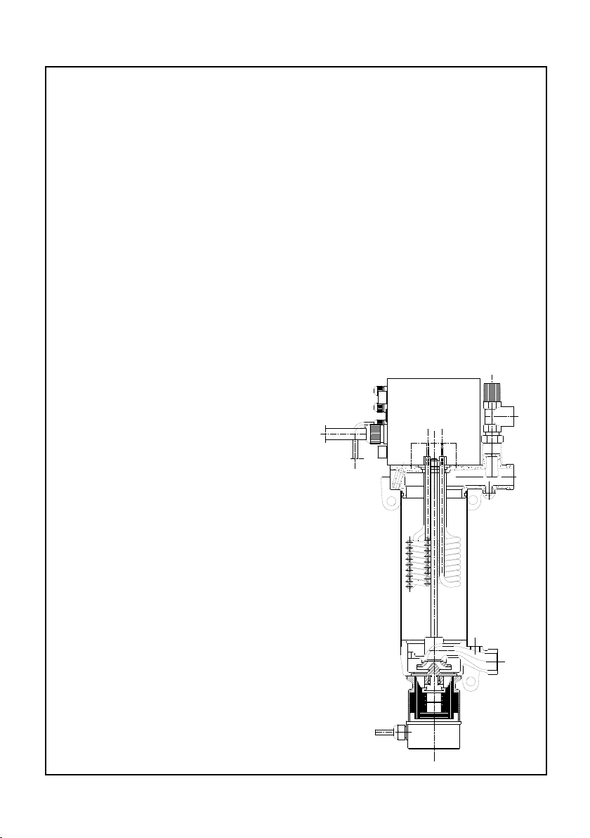
Design of the EPR model
The Electric heater circulator model EPR consists of a circulator pump, an
electric heater with three heating elements and an electronic microprocessor
control.
The spherical motor circulator
operates almost noiselessly and stays
quiet over its lifetime.
The arrangement of the pump below the heating elements guarantees
good heat conductivity from the heating elements since the swirl created
by the impeller extends over the length
of the heating elements. This avoids
overheating of the heating element
surfaces.
The water for the heating loop is drawn
in by the circulator, conveyed along
the heating elements and discharged
through the discharge port at the
upper part of the housing. The inlet
has an additional 3/8” port, to which
an expansion tank can be connected.
An automatic air vent and a pressure
relief valve communicate with the
outlet port.
Mounting eyelets are included in
the castings of the unit.
4
www.lainginc.com
Page 5

Instruction manual Laing Electric heater circulator unit
The Electric heater circulator units EPR 6 to EPR 15 differ only in the performance of the electrical heating elements and the distance between the ports.
EPR 6 has a heating performance of 6000 W, EPR 9 has 9000 W, EPR 12
has 12000 W and EPR 15 has 15000W.
The control unit, which controls a variety of control and safety functions, is
arranged on top of the Electric heater circulator.
Technical Data
Model EPR EPR EPR EPR
6 9 12 15
Pmax. 87 PSI
Tmax. 194°F
Connection on water side Union 1” male
Weight 21.8 lb 22.5 lb 23.8 lb 24.5 lb
Pump
Max. Head 4.6 PSI
Max. Flow 14.9 GPM
Motor
Design Shaftless spherical motor
Watts Input 99 W
Motor performance 35W
Volts AC 230 V
Amperes 0.43 A
Electric Heater
Electrical performance 6 kW 9 kW 12 kW 15 kW
Number of heating elements 3 3 3 3
Heat capacity per element 2 kW 3 kW 4 kW 5 kW
Voltage 400 V, 3P 400 V, 3P 400 V, 3P 4 0 0 V,
3P
Amperes 8.7 A 13.0 A 17.4 A 21.6 A
Connection Y Y Y Y
Safety Temperature Limiter
Maximum temperature 203°F+/- 5 K
www.lainginc.com
5
Page 6
Instruction manual Laing Electric heater circulator unit
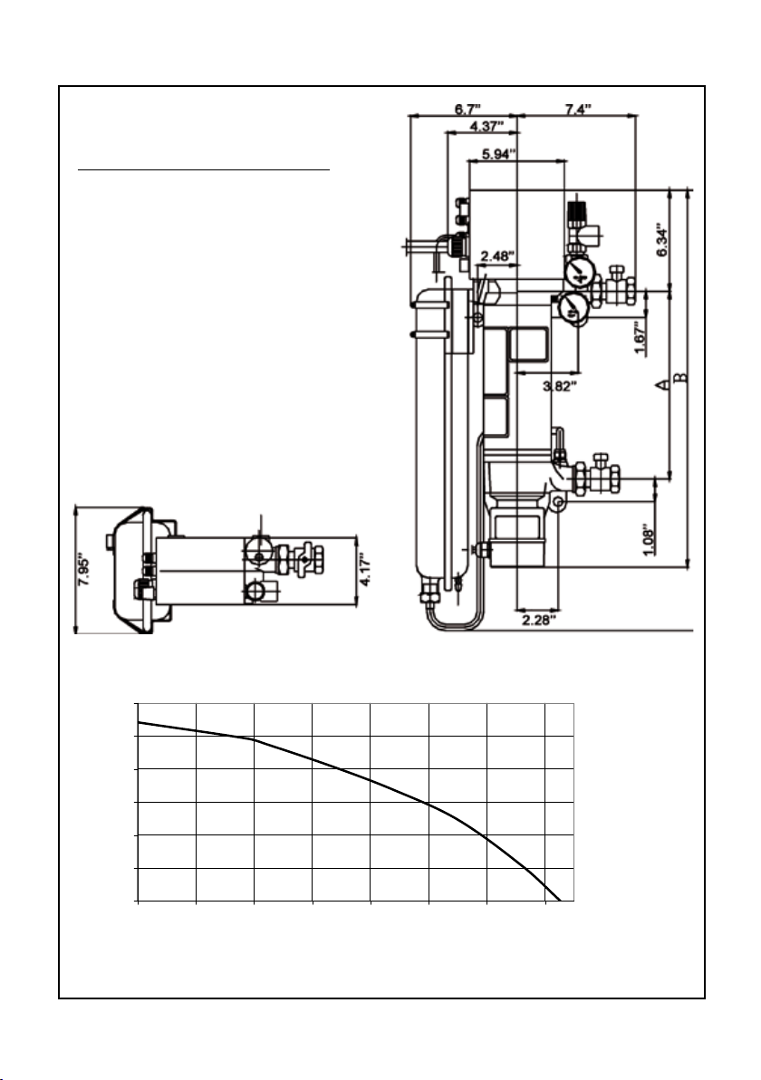
0
2
4
6
8
10
12
0 2 4 6 8 10 12 14
Dimension Drawing
Dimension
Model A B
EPR 6 11.8’’ 23.66’’
EPR 9 11.8’’ 23.66’’
EPR 12 14.37’’ 26.2’’
EPR 15 14.37’’ 26.2’’
Pump curve
Pump head (ft)
6
Flow rate (GPM)
www.lainginc.com
Page 7
Instruction manual Laing Electric heater circulator unit
Mounting
For safety reasons, the Electric heater circulator must be mounted on a
reproof base. In addition, the unit must be installed with the circulator
motor pointing downwards!
The unit must be attached to a at wall with the help of the mounting eyelets
arranged at the top of the unit and at the pump housing. To avoid noise transfer to the wall, both sides of the mounting eyelets have to be covered with
rubber insulators. The rubber insulators are supplied with the Electric heater
circulator unit and have to be mounted in such a way that no metal contact
exists between the castings and the fastening screw. In addition, no part of
the Electric heater circulator unit - for example the outer shell or the pump
- should be in contact with the wall.
The Electric heater circulator should be mounted at least 2.4’’ above the
oor to allow replacement of the circulator motor if necessary.
Connection to the feed and return line
The unit is connected to the heating loop by 1” male threaded t-
Air vent
tings. The feed line is at the top of
the unit, the return line at the bottom. The expansion tank should
be connected to the 3/8” port next
to the return line. If the expansion
tank cannot be connected there, it
should be connected somewhere
else in the return line, but not in
the feed line. There are two ˝”
ports at the top of the unit. The
automatic air vent for the heating
circuit is connected to the ˝” port
Mounting
eyelet
Safety relief
valve
Heating
loop feed
side
Mounting
eyelet
Connection
for expansion tank
closest to the wall, the pressure
relief valve to the port in front.
When the Electric heater cir-
Heating
loop return
side
culator unit is used solely for oor
heating, the chapter “Important
Notice: Proper connection to a
Mounting
eyelet
oor heating system” has to be
observed.
Connection EPR series
www.lainginc.com
7
Page 8
Instruction manual Laing Electric heater circulator unit
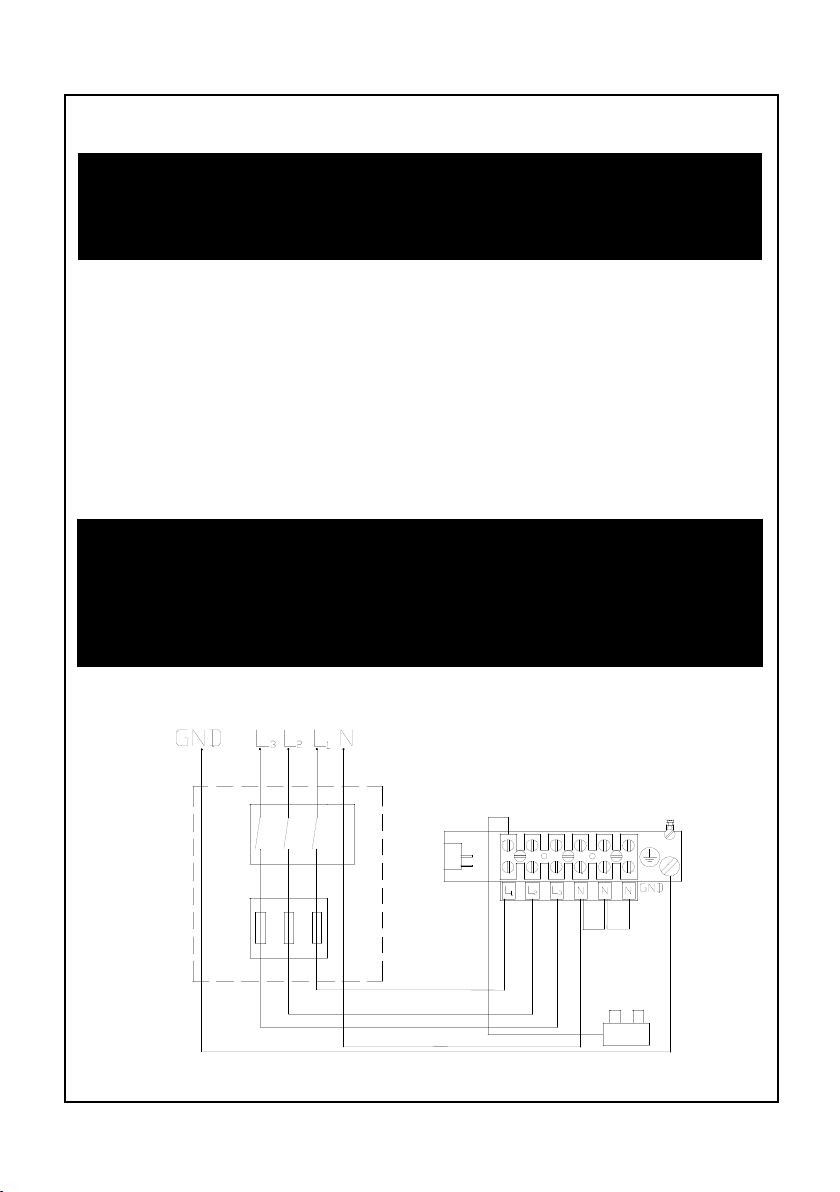
Electrical Connection
Notice: The electrical connection has to be performed by a licensed
electrician!
The pump must not be operated without water.
To make the electrical connections, the control box at the top of the heater
has to be opened by removing the 4 screws. A cable with a sufcient cross
section for the performance of the Electric heater circulator unit has to be
inserted through the strain relief and connected to the input terminal (see
Electrical Diagram below)
The circulator is already wired to the control box.
Power Supply
The Electric heater-circulator is designed for three different kinds of power
supply. In all cases the following information has to be taken into account:
The electronic switches integrated into the Electric heater circulator unit do
not separate the heating elements from the power supply. Therefore, a master
switch that interrupts all phases has to be installed in an accessible place,
taking into account all applicable safety codes.
As a protection for the semiconductor relays each phase has to have a fast
acting fuse.
400V N3 Electrical Diagram
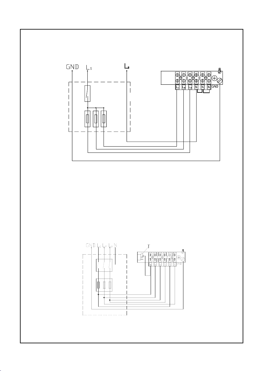
230V N1 Electrical Diagram
8
T
www.lainginc.com
Page 9
Instruction manual Laing Electric heater circulator unit
L2
In this case, the Electric heater circulator unit has to be connected with 7 leads
to protect each of the semiconductor relays separately. After this has been
done, the leads are combined into one phase.
230V N3 Electrical Diagram
In this case, it is important to ensure the proper phase sequence of the connectors 1 to 3 and 4 to 6.
The integrated control
T
T
www.lainginc.com
9
Page 10
Instruction manual Laing Electric heater circulator unit
The integrated microprocessor control in the housing on top of the Electric
heater circulator unit performs a variety of control functions for a large number
of applications.
The heating elements are noiselessly switched by electronic relays.
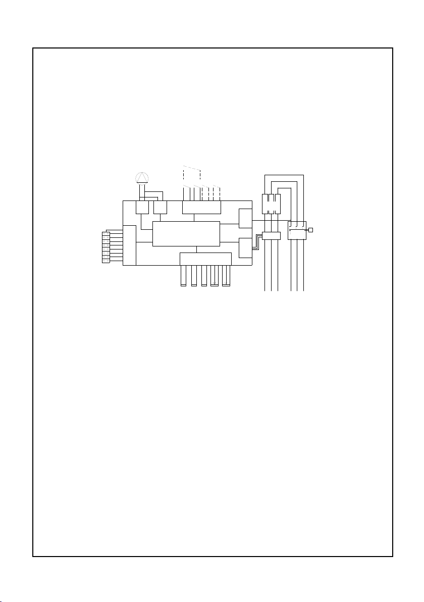
Schematics of the integrated control
The block diagram shows the control in schematic presentation
PI G IS W
TI
Y MP X Q
O
RA
B C D P TS
B Temperature sensor for feed temperature
C Temperature sensor for the safety temperature limiter
D Temperature sensor for the semiconductor relays
G Pump operation control logic
IS Input for external control and remote control
MP Microprocessor
O Control for the semiconductor relays
P Potentiometer for constant temperature setting
PI Pump performance control
Q Safety temperature limiter
RA Analog inputs for temperature sensors and temperature pre-selection
T Potentiometer for safety temperature setting
TI Safety temperature limiter control logic
W Heating elements
X Semiconductor relays
Y Jumper settings for operation mode
Temperature sensor B monitors the temperature of the feed line water and
10
www.lainginc.com
Page 11
Instruction manual Laing Electric heater circulator unit
passes the information on to the microprocessor. The microprocessor then
activates the solid state relays which in turn activate the heating elements
according to the jumper selected program. An independent sensor C also
monitors the temperature of the feed line water and switches the pump off
when the temperature exceeds a pre-set temperature.
A further sensor D monitors the temperature of the solid state relays and
turns off the heating elements in case of overheating.
A special control logic veries the rotation of the circulator and prevents
the heating elements from being turned on if the circulator is not running.
The safety temperature limiter turns the heating elements off permanently - independent of the electronic control - when the temperature exceeds 194°F.
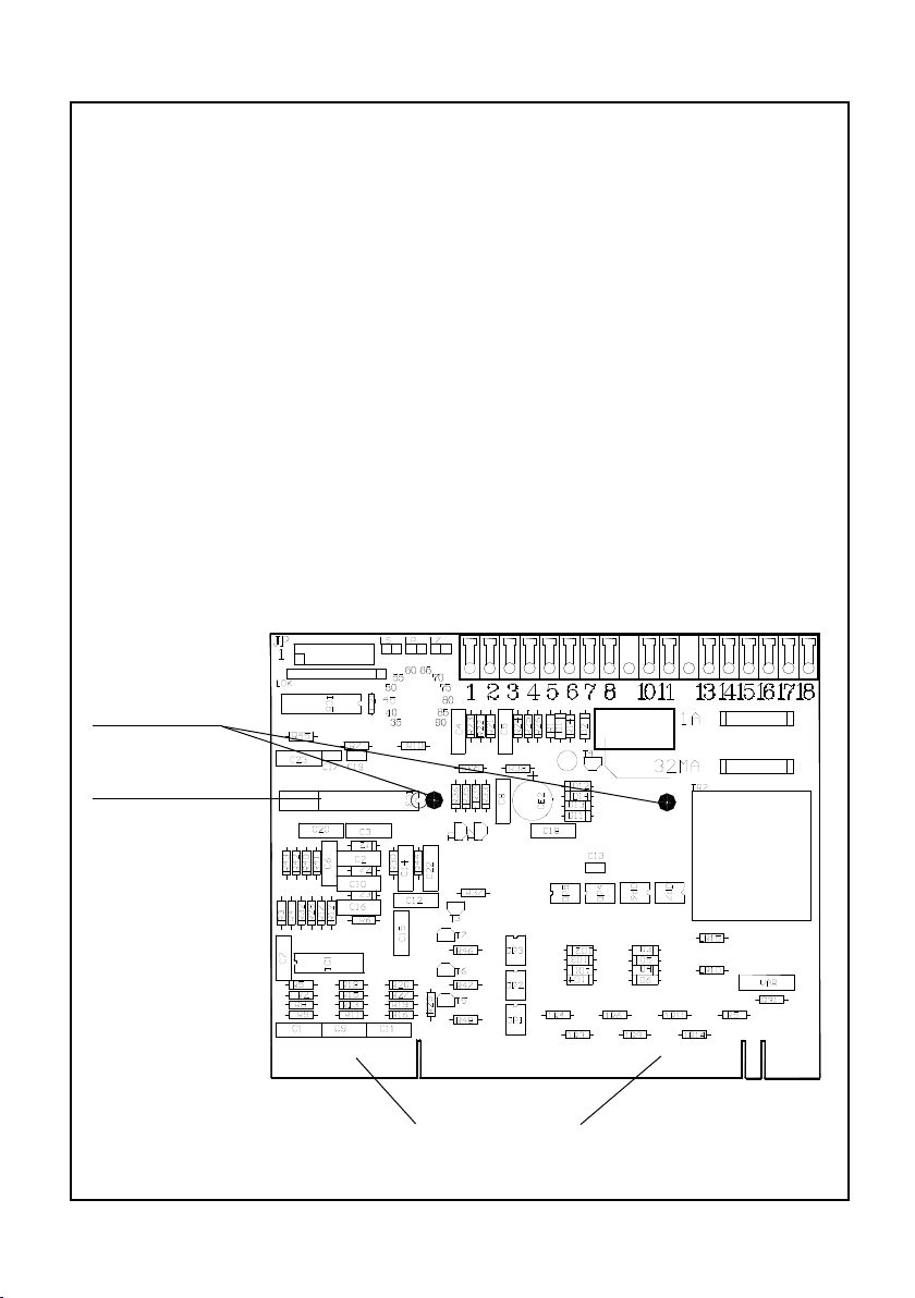
Design of the Main Printed Circuit Board
(See also page 2)
Fastening
points
Processor
Connector for
www.lainginc.com
solid state relays, power supply and sensors.
11
Page 12

Instruction manual Laing Electric heater circulator unit
Functions
Main switch
The Electric heater circulator unit contains a main switch H which powers the
eloctronic control and thereby also controls on – off operation of the heating
elements. The main switch does not separate the unit from the main power
supply. This separation must be provided on site, taking in consideration all
applicable safety codes.
Fuses
To protect the electronic components, the control contains two fuses. The 35mA
fuse protects the processor control, the 1A fuse protects the circulator.
Constant temperature control
The constant temperature control function maintains the feed temperature
of the Electric heater circulator unit at a pre-set level. This is achieved by
measuring the outlet temperature and activating the three heating elements
in accordance with the selected program (See “Program selection for the
switching sequence of the heating elements ”).
The integrated constant temperature function is always activated. Therefore, whenever an external control is used, the constant temperature has to be
set at or above the maximum temperature required by the external control.
The constant temperature can be set with the control knob K at the outside
of the housing. The range is from 86°F to 185°F.
When the electronic safety temperature limiter function is activated, the
selected constant temperature should always be at least 10K lower than
the safety temperature. Otherwise, under unfavorable conditions, the safety
temperature limiter function could be activated, which would shut down the
unit.
Overheating Protection
When the Electric heater circulator unit is used in connection with oor heating
it is strongly recommended to activate the integrated overheating protection
in order to avoid overheating damages due to failure of the control.
To activate this function, jumper 8 needs to be closed. The safety tempe-
rature should be set to the highest permissible temperature for the oor in a
range between 203°F and 194°F at the potentiometer S. This temperature
must be higher than the maximum temperature reached by the oor heating
system under normal conditions!
If activated, the control monitors the feed line temperature with an additional
12
www.lainginc.com
Page 13

Instruction manual Laing Electric heater circulator unit
sensor C and switches off the circulator of the Electric heater circulator unit
if this temperature exceeds the set temperature. This ensures that - indepen-
dent of the function of the control – overheating of the oor heating pipes is
avoided.
Program selection for the switching sequence of the heating elements
The Electric heater circulator unit has three heating elements, each of which
has its own solid state relay. If heat is required, it is normally neither desired
nor necessary that all heating elements are switched on simultaneously.
While this would load all three phases fully, the activation of all three heating
elements could cause overheating at times of off-peak heat demand.
Therefore, several methods can be selected by which the heating elements
will not be switched on at the same time, but staged over time. Moving the
rst jumper between the pins 1 to 4 will perform this task. However, only one
of these jumpers should be closed at any time. If by mistake several jumpers
have been installed, the red and yellow LEDs start blinking and the unit will
not operate.
An overall view of the jumper settings for the switching sequence can be
found on the second to last page of this manual.
A The heating elements will always be switched on simultaneously. This kind
of function can be used with all temperature control methods. If the utility
company does not allow the switching of individual heating elements, this
function must be selected. The disadvantage is that all heating elements
are activated simultaneously and that all three phases are fully loaded even
if the heat requirement is low. If the heat requirement is low, this method
can also lead to overtemperature. To select this function, jumper 1 must
be closed and jumpers 2, 3 and 4 must be open.
B The heating elements are activated depending on the temperature. This
function is only applicable in combination with the integrated constant
temperature control and with room temperature guided control which uses
the constant temperature function.
This function cannot be used with an outside temperature guided control or
another remote control that regulates the feed temperature of the Electric
heater circulator unit.
When the feed temperature is 2K below the set temperature of the con-
stant temperature control, the rst heating element is switched on. If the
temperature drops another 3K, the second heating element is activated.
www.lainginc.com
13
Page 14

Instruction manual Laing Electric heater circulator unit
Another 3K lower, the third heating element is turned on. All heating ele-
ments stay on until the set temperature has been reached.
To select this function, the second jumper must be closed and jumpers 1,
3 and 4 must be open.
This control method has been implemented since it is customary in some
countries. If permitted, control function D is normally preferable.
C The heating elements are activated one after another. This control function
is applicable to all temperature control applications and should always be
used when the feed line temperature is controlled by a remote control,
for instance by an outside temperature guided control, or when the utility
company does not require that all phases are switched on at the same
time. In this case, this method guarantees the highest degree of heating
comfort. When the control detects that heat is needed, rst one heating
element is switched on, after two minutes the second, and after another
two minutes the third.
To select this function, jumper 3 must be closed, jumpers 1, 2 and 4 must
be open.
D The heating elements are activated depending on the heat load. This con-
trol function is recommended in combination with the integrated constant
temperature control, and also with a room temperature guided control,
since this also uses the constant temperature function. This function cannot
be used in combination with an outside temperature guided control that
controls the feed line temperature of the Electric heater circulator unit.
When heat is required, the rst heating element is activated. After a sta-
bilizing time of approximately one minute, the control checks whether the
temperature is increasing or decreasing. If the temperature is increasing,
no further heating elements will be switched on. If the temperature is still
decreasing, the second heating element is turned on. After another minute,
the temperature change will be checked again, and if necessary, the third
heating element will be switched on. All activated heating elements will
stay on until the set temperature has been reached.
If the actual feed line temperature differs considerably from the set tempe-
rature (for instance when the heater is switched on), after approximately
one minute all heating elements will be turned on automatically.
To select this function, jumper 4 must be closed and jumpers 1,2 and 3
must be open.
14
www.lainginc.com
Page 15

Instruction manual Laing Electric heater circulator unit
Pump shut-off
The integrated control is equipped with a pump shut-off option which can be
activated by closing jumper 5.
If the pump shut-off function is not activated, the pump operates always when
the main switch of the control is switched on. If the pump shut-off switch is
activated, the pump only starts when heat is required and runs for about two
more minutes after the heating has been turned off, so that all residual heat
from the heating elements will have been dissipated.
As a general rule, the pump shut-off option should be activated in heating
systems with radiators, while the pump should run continuously in oor heating
applications.
This pump shut-off function is independent from the pump switching of
the pump shut-off module of a zone control, which prevents the pump from
operating when all zone valves are closed. If such a function is desired, a
pump shut-off module is required.
Deactivating heating elements
The Electric heater circulator unit contains three heating elements, which can
be automatically energized by the control. If not all three heating elements are
needed for an application, the second heating element can be deactivated
by opening jumper 6 and heating element 3 can be deactivated by opening
jumper 7. The deactivated heating elements are no longer activated by the
control, unless they are activated by a remote control system.
Remote control of the second and third heating element
This function makes it possible to control the second and third heating elements, which would mean providing one third or two thirds of the heating
capacity, via an external contact.
It can be used to avoid a high peak load in the electric supply line. The
second and/or the third heating element can, for example, be switched off
when the hot water heater is being reheated or when the oven hot plates are
simultaneously in use. The same applies when the Electric heater circulator
unit is operated in a grid with peak demand usage limitations. In this case,
one third or two thirds of the heat capacity can be switched off at peak load
times.
It should, however, be taken into account that the heating elements – even
when they are switched on via the external contact – are only active when
the control signals a heat requirement or when the control, according to the
chosen program for the switching sequence, activates this heating element.
In case all heating elements should be switched by a remote control, the
www.lainginc.com
15
Page 16

Instruction manual Laing Electric heater circulator unit
control entrance should be used (terminals 5 and 6).
To operate the second heating element by remote control, the heating
element has to be deactivated rst by opening jumper 6. The same applies
to the third heating element. In this case jumper 7 has to be opened. Now a
non energized switch can be attached to terminal 1 and 2. Closing this switch
will activate the deactivated heating elements.
Control input
When the Electric heater circulator unit should be controlled by a remote control
unit, this control must be connected to terminals 5 and 8 with a potential free
switch. If two remote controls are to operate in series, one can be connected
to terminals 5 and 6, the other one to terminals 7 and 8. The terminals 6 and
7 are connected internally. For this function, the bridge between terminals 5
and 8 has to be removed. All active heating elements will be switched on and
off by this input in accordance with the selected switching sequence.
The constant temperature control function stays always active. This means
that the set constant temperature must be set at or above the maximum
temperature called for by the remote control (see also “Outside temperature
guided control”)
Room temperature guided control
In connection with a room thermostat RT or a room thermostat with timer RTU,
it is possible to control the Electric heater circulator unit from one room of the
house. In this case, the room thermostat or the thermostat with timer must be
connected to the control input of the Electric heater circulator unit. The room
thermostat or the thermostat with timer should be located in the main room
since it will control the entire heating system.
The thermostat should not be located close to windows, radiators, outside
walls or similar distorting inuences.
The thermostat should be connected according to the electrical diagram
provided with it.
16
www.lainginc.com
Page 17

Instruction manual Laing Electric heater circulator unit
The desired room temperature must be set at the room thermostat. Similarly, the room thermostat with timer should also be properly set. It should be
understood that the room thermostat with timer allows only one lower room
temperature level, which then will be activated by the timer. There will be no
corresponding decrease in the feed line temperature.
Instructions for the operation of the room thermostat with timer should be
taken from the manual provided with the unit.
The desired constant temperature for the feed line water, with which the
heating system will be heated until the room temperature has been reached,
must be set at the setting knob K.
The heating surfaces then will be heated with the preset constant temperature until the preset room temperature has been reached. The heating
elements will then be turned off.
It is important that the set constant temperature is always lower than the
maximum permissible feed temperature. This is especially important for oor
heating applications.
Electrical Diagram RT
Electrical Diagram RTU
www.lainginc.com
17
Page 18

Instruction manual Laing Electric heater circulator unit
Outside temperature guided control
In connection with the outside temperature guided control AR 1000 d it is
possible to control the feed line temperature dependent upon the outside
temperature.In this case the switching terminal of the control unit must be
connected to the control input ot the Electric heater circulator unit and the
feed line sensor must be attached to the correct place at the top part of the
Electric heater circulator unit.(See also chapter “Installation of the feed line
sensor”).
The connection should be made according to the electrical diagram provided with the unit. The settings of the outside temperature guided control
should be taken from the relevant manual.
The constant temperature control is always active. The constant temperature has to be set at least as high as the highest temperature requested by
the outside temperature guided control.
Electrical Diagram AR 1000 d
Safety temperature limiter
In order to protect the Electric heater-circulator from overheating, it is equipped
with a safety temperature limiter, which in case of overheating separates one
side of the heating element permanently from the grid.
When the safety temperature limiter had been activated, it has to be reset
manually by pressing knob Z.
The safety temperature limiter reacts only when there is a malfunction in the
system. Therefore, as a rst step, the malfunction that caused the activation
of the safety temperature limiter has to be corrected.
When the activation of the safety temperature limiter was caused by operating the Electric heater-circulator without water, it is possible that the safety
switch could be damaged permanently. In this case it is impossible to reset the
safety temperature limiter, it has to be replaced. (See chapter “Replacement
of the safety temperature limiter STBR”).
18
www.lainginc.com
Page 19

Instruction manual Laing Electric heater circulator unit
Electronic means to prevent dry running
The Electric heater-circulator can only be operated when it is lled with water
and the circulator is running.
To protect the heating elements when the Electric heater-circulator is ac-
cidentally switched on without being lled with water, or when there is still a
lot of air in the system, the control system has electronic dry run protection,
which turns the heating elements off and gives a warning via the LED’s when
the temperature rises too fast.
In this case the red LED lights up, the yellow stays switched off. To reset
the system, the unit has to be switched off and then on. If the temperature
of the heating elements has fallen below the maximum temperature allowed
by the constant temperature control after the unit has been switched off, the
heater can be activated again. If the temperature is still too high, the unit has
to stay off until the heating elements have cooled down. Of course, the unit
has to be lled with water and the air has to be vented. (See chapter “Filling
of the system”).
The electronic dry run protection safeguards the safety temperature limiter
since in a dry run it could be permanent damaged. When the Electric heater-circulator is turned on and off several times after the electronic dry run
protection was activated, the safety temperature limiter can nevertheless be
damaged. Therefore, after the dry run protection was activated the system
rst has to be lled with water and the air has to be vented before the unit is
switched on again.
Circulator operation control
To avoid the possibility that the heating elements could be switched on while
the circulator is not running, the control is equipped with a circulator operation
control. This means, that each time before the heating elements are turned
on, the control checks whether the rotor of the circulator is rotating. If the rotor
is blocked by dirt or if the bearing of the circulator is totally worn, the control
recognizes it and the heating elements will not be switched on.
In this case the circulator will be energized for about one minute. The control then tests again whether the rotor is rotating or not. If the rotor still does
not rotate, the same procedure is repeated ten times. If the rotor still does
not rotate, the control signals malfunction, which is indicated by the blinking
of the red LED and shining of the yellow LED.
In this case the circulator has to be removed to nd the cause for the
malfunction. (See also chapter “Replacement of the circulation pump”).
www.lainginc.com
19
Page 20

Instruction manual Laing Electric heater circulator unit
Malfunction detector
The control recognizes the following malfunctions:
(the green LED always shines when the main switch is turned on and there
is a connection to the grid; the yellow LED shines when the control requests
heat and the heating elements are activated.)
Malfunction Signal red LED yellow LED
Circulator malfunction blinking on
Excess temperature cutout on on
Safety temperature limiter blinking off
Dry run on off
Jumper 1 to 4 wrong position blinking blinking
The malfunction signal “Jumper 1 to 4 wrong position” means that more than
one jumper is closed or all four jumpers are open. Only one of the jumpers 1
to 4 must be closed.
Beside the indication of the malfunction through the LED’s on the upper side
of the control box, each function effects the closing of a relay which bridges
the contacts 10 and 11. This makes it possible to sound an alarm at each malfunction of the Electric heater-circulator, or to activate other heating systems
or to inform an overriding control.
Electrical diagram to address a horn with the alarm output
20
www.lainginc.com
Page 21

Instruction manual Laing Electric heater circulator unit
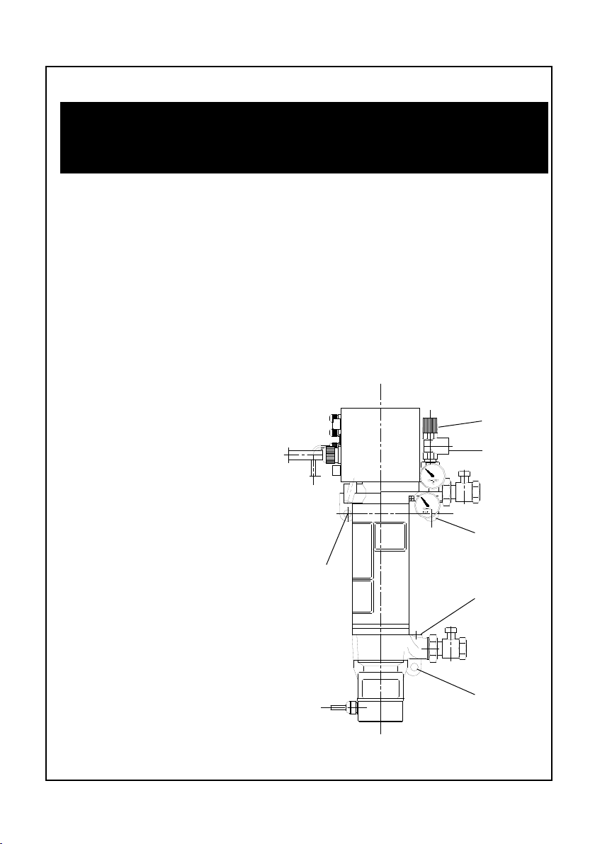
Attachment of the sensor for the remote control
The sensor for the control of the feed line temperature for an outside temperature guided control can be mounted either on the upper part of the housing
that has a hole for a round sensor, or at the feed line of the heating loop, or
in the upper part of the tubular shell of the Electric heater-circulator.
If the sensor is attached to the feed line or to the manifold, one has to take
care that the sensor is in intimate contact with the feed line with the help of
heat conducting paste (in no case should the sensor be attached to a plastic
part). If the sensor is attached to the manifold of the feed line, the sensor has
to be placed before the rst loop.
If the sensor is attached to the tubular shell one has to take care that the
total surface of the sensor facing the shell is in direct contact and that the
sensor is attached to the upper section of the shell!
Se nso r mou nting in the
immersion shell:
The sensor will be inserted
into the hole at the upper
part of the Electric heatercirculator with heat transfer
paste.
The sensor for the control can be mounted according to the
www.lainginc.com
Senso r mo unt ing at the
tubular shell:
The sensor has to be attached as high as possible
on the tubular shell. Attention must be paid to insuring
good heat transfer contact.
Senso r mo unt ing at the
feed pipe:
possibilities shown here.
The sensor has to be attached before the outlet
of the rst loop and has to
have contact to metal.
21
Page 22

Instruction manual Laing Electric heater circulator unit
Indirect domestic hot water heating with the Electric heater-circulator
EPR
Indirect domestic hot water heating
During the heating period the heating of the domestic hot water normally
is performed by the domestic hot water heater that is essentially a heat
exchanger. When hot water is needed, the water from the hydronic heating
circuit is conveyed through this heat exchanger by activating the hot water
heater priority circuit control. This means that the circulator for the heating
circuit is shut off and the charging circulator for the domestic hot water heater
is switched on. In addition the temperature of the boiler will be increased to
the temperature necessary to heat the domestic hot water.
However, this system can only be operated economically during the heating period. Outside the heating period it is uneconomical to run the boiler
just for heating of the domestic hot water. Therefore it is customary, to have
an electric heating element beside the heat exchanger within the boiler that
heats the domestic hot water outside the heating period.
This method is problematic when the water is extremely corrosive or when
the water is hard. It is possible that the heating elements survive only a few
month in such a situation.
In these cases it is advantageous to heat the hot water heater outside the
heating period also with electricity but indirectly via the Electric heater-circulator EPR that is ideal for this application.
By adding an additional printed circuit the Electric heater-circulator EPR
can easily be integrated into existing controls.
Starting operation of the domestic hot water heating and adaptation to
seasonal change
To start the Electric heater-circulator the constant temperature has to be set
to the desired value, normally about 158°F. The circulator then has to be switched to time delay (close jumper 5) for the switching sequence of the heating
elements D, which means, jumper 1,2 and 3 must be open, jumper 4 has to
be closed. Now the Electric heater-circulator is ready for operation.
To change to the heating season when the boiler is in operation, the main
switch has to be shut off while outside the heating season the main switch
has to be turned on. In this latter case the heating of the domestic hot water
is performed by the Electric Heater-circulator. Even outside the heating period
the boiler control has to stay operational.
22
www.lainginc.com
Page 23

Instruction manual Laing Electric heater circulator unit
Hydraulic connection of the EPR for domestic hot water heating
As can be seen from the following diagrammatic drawings, the Electric heatercirculator will be connected in parallel to the boiler and to the heat exchanger
of the hot water heater. To avoid ow through the boiler while heating with
the Electric heater-circulator and vice versa, the boiler as well as the Electric
heater-circulator is connected via a check valve.
Sinc e th e he a t ing
syst e m is al r e ady
equipp e d wi t h an
expansion tank, the
Electric heater-circulator does not need a
separate expansion
tank. The pressure
relief valve integrated
into the Electric heater-circulator serves
as security.
T o s w i t c h
between boiler-heating and electrical
heating nothing has
to be changed on the
hydraulic installation.
One has only to take
care that instead of
the hot water heater
circulator the Electric
heater-circulator has
to be switched on
as described in the
following chapter.
Hydraulic diagram for control process 1
www.lainginc.com
Hydraulic diagram for control process 2
23
Page 24

Instruction manual Laing Electric heater circulator unit
Electrical connection of the EPR for domestic hot water heating
Following two possibilities are described for the connection of the EPR. To
guarantee proper operation the exact function of the boiler control has to be
known.
During the summer boiler controls with domestic hot water priority circuit
control operate by detecting the domestic hot water heater temperature. If
the detected temperature falls below the desired temperature there are two
versions of operation:
The control starts the burner and the hot water heater feed pump at the
same time. If this is the case, it is easily possible to install the Electric heatercirculator EPR as described below under “Control method 1”. No additional
sensor in the hot water heater is necessary.
The control rst turns on the burner and activates the water heater feed
pump only when the temperature of the water heater is at least 122°F. Since
the burner is switched off during summer time, the control of the domestic hot
water heater is only possible with an additional sensor in the hot water heater.
In this case one has to follow the diagram described under “Control method
2”.
For both control methods the additional printed circuit board Type EPRBW
will be needed when the Electric heater-circulator is used to heat the domestic
hot water. After removing the cover of the control box this circuit board has
to be connected to the terminals 5, 8, 13 and 14 of the main printed circuit
board.
Control method 1
The wiring has to be performed according to the wiring diagram shown below, whereby the leads of the hot water heater feed pump loop through the
control of the Electric heater-circulator. The lead III of the pump coming from
the boiler will be connected to ground and phase at CS1. Lead II leading
to the pump will be connected to CS2. In addition a control lead IV will be
connected to CS3, which prevents the boiler from turning on as long as the
electric heating is activated.
As long as the electric heating is switched off via the main switch the relay
on the additional printed circuit board is de-energized and the lead wire for
the hot water heater feed pump is properly connected. In addition the control
contact of this relay is closed for the burner, so that the boiler now takes care
of the heating of the domestic hot water. In this case the check valve of the
Electric-heater-circulator is closed and the check valve to the boiler is open
as long as the hot water heater feed pump is running.
As soon as the main switch of the Electric heater-circulator is turned on,
24
www.lainginc.com
Page 25

Instruction manual Laing Electric heater circulator unit
the relay on the additional printed circuit board closes and switches the lead
from the hot water heater feed pump to
the control inlet of the Electric heatercirculator. At the same time the control
lead for the boiler is interrupted, which
ensures that the boiler and the Electric
heater-circulator cannot be working at
the same time.
Each time the boiler control switches
open with EPR on
on the hot water heater feed pump,
the Electric heater-circulator is turned
on instead.
Wiring diagram control method 1
Control method 2
For this control method it is necessary to install an additional thermostat into
the hot water heater that closes when heat for the hot water heater is needed.
The wiring has to be performed according to the diagram below, whereby
the additional heater thermostat has to be connected to the terminal CS4. A
control lead IV has to be connected to CS3 which prevents the burner from
turning on when the electric heating is active.
As long as the electric heating is switched off via the main switch the relay
on the additional printed circuit board is
de-energized and the control contact of
this relay.
for the burner is closed, so that the
boiler now performs the heating of the
domestic hot water. In this case the
check valve of the Electric heater-circulator is closed and the check valve
for the boiler is open as long as the hot
water heater feed pump is running. As
soon as the main switch of the Electric
heater-circulator is closed, the relais
on the additional printed circuit board
open with EPR on
closes and separates the control lead
to the burner. Now the Electric heater-circulator will be controlled via the
additional thermostat installed within
the hot water heater.
Wiring diagram control method 2
www.lainginc.com
25
Page 26

Instruction manual Laing Electric heater circulator unit
Operation of heating elements with a load shedding device
The control of the electric heater circulator unit is perfectly suited for operation
with a load shedding device.
Normally, utility companies will provide a load shedding device with a potential
free contact which is closed when electrical heating is permitted and open
when electrical heating is not permitted.
- If the load shedding device should not control all heating elements, the
switching contact RR of the load shedding device needs to be connected
to terminals 1 and 2 of the electric heater circulator unit. In this case, the
main power should be connected as described in the chapter “Power
Supply“.
In this case, the rst heating element is always activated when heating
is required, and for the second and third heating element jumpers 6 and
7 control whether they are controlled by the load shedding device. If the
appropriate jumper is closed, the element heats always when heat is requested. If it is open, the heating element only heats when in addition to
the heat request
the contact between terminal 1
and 2 is closed.
In this way, it is
possible to control
one third or two
thirds of the total
heating power by
a load shedding
device.
26
Wiring schematics for load shedding device if only one
or two heating elements are to be controlled by the
load shedding device.
www.lainginc.com
Page 27

Instruction manual Laing Electric heater circulator unit
- If all three heating elements should be controlled by a load shedding
device, the unit needs to be connected according to the diagram below.
The diagram shows the connection for 3-phase 400 Volt operation. For
other supply voltages, the corresponding diagram shown under “main
power connection“ should be modied accordingly.
If all three elements are controlled by a load shedding device, a separate
power supply is needed for the control and the circulator pump, so that
these two can operate independent of the load shedding device. This is
necessary since an operation of the unit without deferred pump shutdown
can lead to overheating conditions when the elements are deenergized.
Remove the jumper wire
between Mains terminal
1 and terminal T on the
main switch. Attach the
separate power supply
to terminal T. A separate
switch H1 controls the
operation of pump and
control as well as the contactor for the main power
supply.
If the load shedding device RR is open but the
switch H1 and the main
switch of the electric heater cir-culator unit are on,
the control and the pump
will operate. When the
co ntact RR is closed,
the external contactor
closes and the heating
elements are activated in
accordance with heating
require-ments and selected heating program.
Wiring schematics for control of all heating elements by load shedding device
www.lainginc.com
27
Page 28

Instruction manual Laing Electric heater circulator unit
Filling of the system
One has to take care that the whole system is completely lled.
In lling and bleeding of a oor heating system one has to take into con-
sideration that the gases released from the water have no opportunity to
accumulate for instance in radiators as in other heating systems. In a oor
heating the gases will always circulate in the heating loops. In cases with high
emission of gas the circulator may stop running, whereby the bearing, due to
dry running, can be damaged. Therefore one has to take care that after about
two weeks the collected gases are completely vented, and that a comparable
amount of water is added.
The electric heating should only be started after complete lling and bleeding of the system.
Pressure and leak tests
When pressure-testing the system, the expansion tank, the pressure relief
valve, and the manometer should never be exposed to the pressure necessary
to perform the pressure test. These parts have to be removed and the holes
have to be plugged.
Starting operation
The system can only be started when it is completely lled and when the
control system has been tested. When using a remote control one has to
make sure that the feed line sensor is attached to the feed line. In addition
one has to take care that the jumper of the control are in the right position to
guarantee the desired functions.
If these preconditions are fullled, the pump can be switched on rst by
setting the constant temperature at knob K at the lowest value and by activating the main switch. It is possible that there could be some noise in the
system due to residual air. If this noise does not stop after a few minutes or
if no liquid is circulated by the pump, the pump should be switched on and
off several times (about 10 seconds off, 20 seconds on) to enhance the air
venting. If this method does not succeed after about 10 minutes, the lling of
the system has to be repeated since apparently there is still a large amount
of air in the system.
In no case should the pump run longer than a few minutes in a system
inadequately vented since the bearing can be damaged.
After a successful start of the pump in a oor heating system the unit should
run for about 24 hours without heating to give the water time to get rid of
the gases. After this time the heating should start by slowly increasing the
28
www.lainginc.com
Page 29

Instruction manual Laing Electric heater circulator unit
feed line temperature via the constant temperature setting. During the whole
starting operation the system has to be controlled and the water which is
diminished by the release of the gases has to be replaced and the gases
have to be vented.
If this advice is not followed, there is the danger that the air accumulates in
the pump and interrupts the circulation of the pump. In this case the bearing
can also be damaged.
Replacement of the circulation pump
In case it is necessary to open or replace the circulator of the Electric heatercirculator, the Electric heater-circulator has to be separated from the grid and
the water has to be drained.
If the Laing Compact station is used, the return line valves of all heating
loops have to be closed and a hose has to be attached to the lower KFE
tap. After opening the KFE tap about 0.9 to 1.8 Gallons of water will be
discharged.
Now the pump has to be taken off by unscrewing the two fastening screws.
When the pump is removed it should not be tilted too much since otherwise the
rotor might fall out and could be damaged. After the pump has been removed
the rotor can be drawn off upwards and can be tested for dirt of scaling.
In replacing the pump the rotor has to be replaced before the seal ring otherwise there could be damage. Before the Electric heater-circulator is started
again the air has to be vented in any case.
Replacement of the safety temperature limiter STBR
To replace the switching module of the safety temperature limiter the leads
of the safety temperature limiter have to be marked and than disconnected.
Thereafter, the switching module has to be removed by unscrewing the nut
around the reset knob Z at the outside of the control box . Then the capillary
has to be carefully removed from the immersion shell. One has to take into
account that the temperature sensors are also contained in the immersion
shell.
Afterwards, the temperature sensors have to be removed from the old
capillary and be attached to the new capillary in the same position directly
above the thick area of the capillary. This point is very important since an
improper mounting can lead to a malfunction of the control.
Then the capillary has to be carefully replaced into the immersion shell
www.lainginc.com
29
Page 30

Instruction manual Laing Electric heater circulator unit
until it touches the bottom. Thereafter, the safety temperature limiter has to be
secured by the nut and the leads have to be connected to the same positions
as before.
Replacement of the main circuit board EPRH
To replace the main circuit board the Electric heater-circulator has to be disconnected from the grid and thereafter, the cover from the terminal box has
to be removed.
Then two snap connectors M have to be disengaged by pressing with a screw
driver from above on the tongue of the connector (see page …). Thereafter
the circuit board can be pulled out. One has to take care that the leads that
are pinned to the circuit board will not get stuck. When the circuit board has
been moved up high enough, the leads can be removed.
Before the circuit board is reinserted, the plugs have to be fully inserted into
the board. One has to make sure that the slots in the circuit board t into the
bars of the plugs.
Thereafter the circuit board is pushed downwards until the snap connectors
are in the right position and the board can be snapped in.
Important Notices
Important Notice: How to avoid noise problems
Since the Electric heater-circulator is often used in living quarters, it is especially important to avoid noise. In this respect it is very important that the
Electric heater-circulator and the connected pipes are always joined by rubber
isolatorsto avoid direct sound transmission. This applies also to pipes installed
inside the walls.
Important Notice: How to avoid overheating
To avoid overheating of the Electric heater-circulator it is obligatory that
during the heating cycle the Electric heater-circulator is continuously lled
with water. If the feed line or the return line will be shut off as for instance in
a oor heating system, in which all loops have a zone control, the optionally
available Laing Zone module with pump shut off has to be installed. This will
shut off the pump until a through ow is possible again. In heating systems
with radiators a relief valve has to be installed.
Important Notice: In the event of safety temperature limiter failure
When the safety temperature limiter will become very hot, as can be the case
when the Electric heater-circulator is switched on and off several times without
being lled with water, the safety temperature limiter will switch off once more
30
www.lainginc.com
Page 31

Instruction manual Laing Electric heater circulator unit
to avoid a further overheating. However, it may not be possible to switch it
on again since the high temperatures may have destroyed the element. This
damage is recognizable when the knob of the switch for the safety temperature
limiter cannot be engaged any more. If this is the case, the safety temperature
limiter has to be replaced.
Important Notice: For proper connection to a oor heating system
All parts of the Electric heater-circulator and all other components which are
part of the Laing compact- or central stations, which come in contact with the
liquid conveyed are corrosion resistant. Therefore it is possible to provide
a direct oor heating system connection even if the pipes are not diffusion
protected.
However, this applies only when the whole oor heating loop consists of
corrosion resistant material. In any case installations having corroding materials such as iron expansion tanks, iron pipes or radiators should be avoided.
In such installations – even when they are diffusion protected – excessive
corrosion will occur in a short time on the iron parts which in turn can lead to
other damages and even water leaks in the system. In these systems only a
separation between the systems can solve the problem.
Factory settings
Constant temperature control 122°F
Safety temperature cutout 140°F
Jumper 1 closed
Jumper 2 open
Jumper 3 open
Jumper 4 open
www.lainginc.com
Jumper 5 open
Jumper 6 closed
Jumper 7 closed
Jumper 8 closed
31
Page 32

Instruction manual Laing Electric heater circulator unit
Switching sequence Jumper 1 2 3 4
A Simultaneous switching closed open open open
B Switching in temperature steps open closed open open
C Switching staged over time open open closed open
D Switching depending on a gradient open open open closed
In connection with an outside temperature guided control only A and C can
be used.
Jumper Function jumper closed Function jumper open
5 After switching off the heating Circulator runs always as long
elements the circulator runs as the main switch is turned on
another two minutes
6 Second heating element Second heating element
activated deactivated
7 Third heating element Third heating element
activated deactivated
8 Overheating safety switch Safety temperature switch not
activated activated
Malfunction reports and LED’s
(the green LED is always on when the main switch is turned on and there is
a connection to the grid, the yellow LED is on when the control requests heat
and when the heating elements are activated.)
Malfunction Signal red LED yellow LED
Circulator malfunction blinking on
Excess temperature cutout on on
Safety temperature limiter blinking off
Dry operation on off
Jumper 1 to 4 wrong position blinking blinking
The malfunction signal “Jumper 1 to 4 wrong position” means that more than
one jumper is closed or all four jumpers are open. From the jumpers 1 to 4
only one jumper must be closed.
32
www.lainginc.com
Page 33

Instruction manual Laing Electric heater circulator unit
www.lainginc.com
33
Page 34

Instruction manual Laing Electric heater circulator unit
34
www.lainginc.com
Page 35

Instruction manual Laing Electric heater circulator unit
www.lainginc.com
35
Page 36

290607 Subject to change without notice · Errors and omissions exceptetd
Phone: (619) 575-7466 · Fax: (619) 575-2739 · E-Mail technicalsupport@lainginc.com
Laing Thermotech, Inc. · 830 Bay Blvd. Suite #101 · Chula Vista, CA 91911
or customerservice@lainginc.com · Internet: www.lainginc.com
 Loading...