

Page 1

ecocirc XL
ecocirc XLplus
ELECTRONIC DRIVE MANUAL
Page 2

1 Introduction
1
2
3
The electronic drive described in this manual controls
both ecocirc XL and ecocirc XLplus circulators; the
drive’s main features are:
sensorless motor control
sine wave modulated PWM
2 micro-controllers:
one dedicated to motor control
one implementing the following features:
- several operating and control modes
- night mode operation
- 0-10V analog input signal control
- PWM input signal control1
- 4-20mA pressure sensor control
- external temperature sensor control2
- external start/stop signal control
- fault signal control
- connection to Modbus control
systems2
- connection to Bacnet control systems3
multiple alarms and errors detection and
control
multiple pump status indication
optional Wireless module control2
optional RS485 module control2
In the next chapters, a detailed description of ecocirc
XL family drives’ features will follow.
Only on plug-connected models, see 1.1
Only on ecocirc XLplus
Only on ecocirc XLplus terminal-connected models, see 1.1
Page 3

Circulator model
Options
Electrical connection
ecocirc XL/XLplus 25-40
(B)
Plug
ecocirc XL/XLplus 25-60
(B)
Plug
ecocirc XL/XLplus 25-80
-
Terminal
ecocirc XL/XLplus 25-100
-
Terminal
ecocirc XL/XLplus 32-40
(B)
Plug
ecocirc XL/XLplus 32-60
(B)
Plug
ecocirc XL/XLplus 32-80
(F) (B)
Terminal
ecocirc XL/XLplus 32-100
(F) (B)
Terminal
ecocirc XL/XLplus 32-120 F
(D) (B)
Terminal
ecocirc XL/XLplus 40-80 F
(D)
Terminal
ecocirc XL/XLplus 40-100 F
(D)
Terminal
ecocirc XL/XLplus 40-120 F
(D) (B)
Terminal
ecocirc XL/XLplus 50-80 F
(D) (B)
Terminal
ecocirc XL/XLplus 50-100 F
-
Terminal
ecocirc XL/XLplus 50-120 F
(D) (B)
Terminal
ecocirc XL/XLplus 65-80 F
(D) (B)
Terminal
ecocirc XL/XLplus 65-120 F
(D) (B)
Terminal
ecocirc XL/XLplus 80-120 F
(D)
Terminal
ecocirc XL/XLplus 100-120 F
-
Terminal
All the subsequent circulators must be considered XLplus models
ecocirc XL 20-35
(B)
Terminal
ecocirc XL 36-45
(B)
Terminal
ecocirc XL 15-75
(B)
Terminal
ecocirc XL 55-45
(B)
Terminal
ecocirc XL 20-140
(B)
Terminal
ecocirc XL 65-130
(B)
Terminal
ecocirc XL 40-200
(B)
Terminal
ecocirc XL 70-145
(B)
Terminal
ecocirc XL 40-275
(B)
Terminal
ecocirc XL 95-125
(B)
Terminal
ecocirc XL 27-375
(B)
Terminal
ecocirc XL 105-155
(B)
Terminal
ecocirc XL 45-340
(B)
Terminal
1.1 Product Range
B = Bronze
F = Flanged
D = Twin
Page 4

ecocirc XL /
XLplus
Voltage
rating
Nominal
max input
current
Recommen
ded line
protection
[A]
[A]
25-80
25-100
32-80
32-100
40-80
40-100
50-100
36-45
15-75
1 230V
50/60Hz
<2
3
32-120
40-120
50-80
65-80
55-45
1 230V
50/60Hz
<3
4
50-120
65-120
65-130
1 230V
50/60Hz
<5
6
80-120
100-120
70-145
1 230V
50/60Hz
<9
10
Plug
connector
M12 (1)
Cable Ø
2÷5mm
M12 (2)
Cable Ø
2÷5mm
Power supply
3x
0.75÷1.5
mm2
(2P+T)
Fault signal
2x
0.75÷1.5
mm2
- Analog 010V
- External
pressure
sensor
- External
temperature
sensor
- External
start/stop
If NO fault
signal on
this cable
gland.
Multi-wire
control
cable,
number of
wires
according
to number
of control
circuits.
Shielded if
necessary
Multi-wire
control
cable,
number of
wires
according
to number
of control
circuits.
Shielded if
necessary
Communicati
on bus
Bus cable
M20 Cable
Ø 5÷13mm
M16 (1)
M16 (2)
Power supply
3x
0.75÷2.5
mm2
(2P+T)
- Power
supply
- Fault signal
5x
0.75÷1.5
mm2
(4P+T)
Fault signal
2x
0.75÷1.5
mm2
2 Electrical installation
Power Supply: 1 x 230V ±10%, 50/60Hz
Check that the power supply line is provided with:
A mains isolator switch with a contact gap of at
least 3mm
A high-sensitivity (HS) 30mA differential switch
(RCD – Residual Current Device), suitable for
earth fault currents with DC or pulsating DC
content (preferably Type B).
If an automatic circuit breaker (CB) is required,
use an automatic circuit breaker with C-type
characteristic curve.
a. Connect the ground (earth) lead; be sure
that the ground (earth) lead is longer than
the phase leads
b. Connect the phase leads
For cable requirements and organization of wiring
harness inside the cable glands, refer to par. 2.3
Wiring harness.
2.2 I/O connection
1. Open the terminal block removing the screws
2. Connect the appropriate cable according to the
terminal block diagram. See Figure 8, Figure 9 and
the requirements of par. 2.3 and 2.4.
2.3 Wiring harness
For plug-connected models
2.1 Power Supply connection
For plug-connected models, see Figure 6 and follow
the subsequent steps:
1. Open the connector cover and insert the cable
inside the cable gland
2. Pull down the contact retention spring
3. Connect the cable according to the wiring diagram
4. Align the two parts of the connector
5. Push the two parts one inside the other
6. Close the connector and tight carefully the cable
gland
For terminal-connected models, see Figure 5 and
follow the subsequent steps:
1. Open the terminal block cover removing the
screws
2. Insert the cable inside the M20 cable gland
3. Connect the cable according to the wiring diagram
(see Figure 7 and Figure 9)
Table 1
Table 2
For terminal-connected models
Page 5
- Analog 010V
- External
pressure
sensor
- External
temperature
sensor
- External
start/stop
If NO fault
signal on
this cable
gland.
Multi-wire
control
cable,
number of
wires
according
to number
of control
circuits.
Shielded if
necessary
Multi-wire
control
cable,
number of
wires
according
to number
of control
circuits.
Shielded if
necessary
Communicati
on bus
Bus cable
Function
Terminal
pair
Contact rating
See
par.
External
start/stop
The drive
provides 5VDC
through these
terminals: no
external voltage
must be
provided!
2.5.1
0-10V external
analog input
2.5.2
Fault signal
Max 250V at 2A
(inductive load)
2.5.3
4-20mA
pressure sensor
input
2.5.4
External
temperature
sensor4
The drive works
with a KTY83
temperature
sensor (1KΩ at
25°C)
2.5.5
Communication
bus (standard)4
TIA/EIA RS485
2.5.6
Communication
bus (optional)4
TIA/EIA RS485
2.5.7
Optional
Wireless /
RS485 module
2.5.8
4
Vin
thres
holds
[V]
Speed
setpoint
[rpm]
when
Vin
Pump
status
when Vin
Po
int
Speed
setpoint
[rpm]
when
Vin
Pump
status
when Vin
Po
int
0
-
Input
disabled
-
-
Input
disabled
-
0.8
-
Input
disabled
- 0 OFF
1.19
-
Input
disabled
- 0 OFF
1.20 0 OFF
MIN
RUN
1.49 0 OFF
MIN
RUN
1.50
MIN
RUN
MIN
RUN
10.0
MAX
RUN
MAX
RUN
Table 3
2.4 Connection diagram
With reference to Figure 8 and Figure 9:
and , which is the factory setting, should be
maintained.
NOTICE
The drive provides 5VDC through these terminals: no
external voltage must be provided to these terminals!
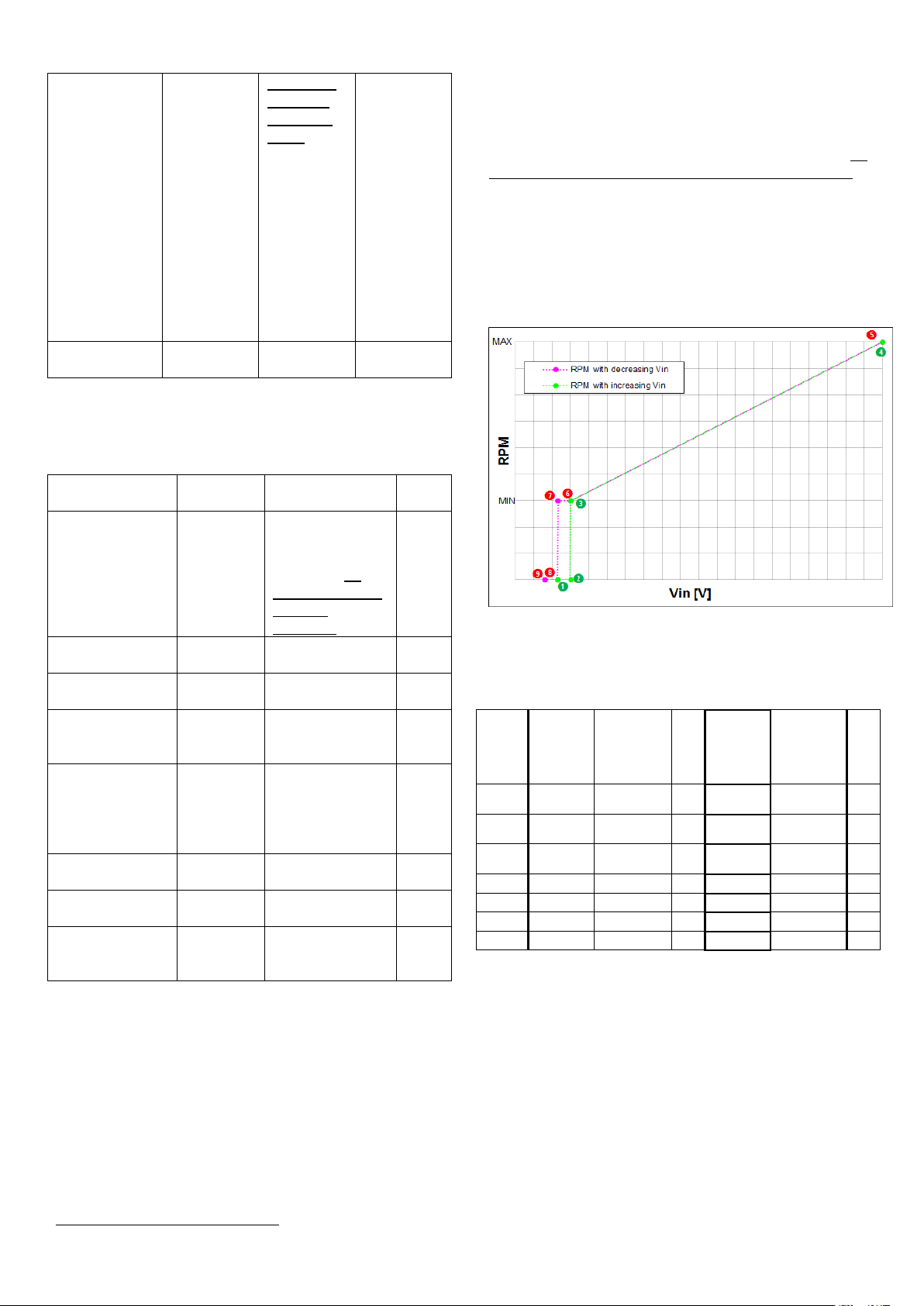
2.5.2 External analog input 0-10V []
An external analog signal 0-10V, applied to terminals
and , controls the circulator speed in a range from
0 to 100%, following a linear function as depicted in
Figure 1.
2.5 I/O description
2.5.1 External start/stop []
The circulator can be started or stopped via an
external potential-free contact or a relay connected to
terminals and . If no external start/stop switch is
connected, the connection jumper between terminals
Only on ecocirc XLplus
Table 4
Figure 1
In the below table a description of the milestones
shown in Figure 1.
Table 5
2.5.3 Fault signal []
The drive controls a relay for a potential-free fault
signal: in case of blocking error, the relay is activated
so that the terminals and are short circuited.
RATINGS
V
< 250VAC
max
I
< 5A (if resistive load)
max
I
< 2A (if inductive load)
max
Page 6

Interface
RS485 (TIA/EIA) optically isolated
Baud rate
4800 / 9600 (factory setting) / 14400 /
19200 / 38400 / 56000 / 57600 baud
Data
format
8 data bits, no parity, 1 stop bit
Protocol
Modbus RTU (factory setting)
Bacnet MSTP5
Address
1247 Modbus RTU
0 127 Bacnet MSTP5
ID #1 factory setting
Interface
RS485 (TIA/EIA) not isolated
Baud rate
4800 / 9600 (factory setting) / 14400 /
19200 / 38400 / 56000 / 57600 baud
Data
format
8 data bits, no parity, 1 stop bit
Protocol
Modbus RTU (factory setting)
Bacnet MSTP
5
Address
1247 Modbus RTU
0 127 Bacnet MSTP5
ID #1 factory setting
Priority
Possible settings
User
Interface
External
Start/Stop
External
0-10V
Bus signal
1 Stop 2
Regulation
3 Stop
4
Regulation
5 Stop
6
Regulation
7 Stop
2.5.4 External analog input 4-20mA []
The circulator can be equipped with a 4-20mA external
differential pressure sensor, connected to terminals
and , with the purpose of increasing the precision in
operating modes involved with pressure regulation.
For setting, in the drive, the correct pressure sensor
model used, see par. 4.3.5.3.
2.5.5 External temperature sensor []
The circulator can be equipped with an external KTY83
temperature probe (1KΩ at 25C), connected to
terminals and , with the purpose of measuring an
absolute or a differential water temperature, in
temperature dependent / influenced operating modes.
For setting, in the drive, the desired temperaturedependent control mode, see par. 6.1.2
2.5.6 Communication bus (standard)
[]
The circulator (model ecocirc XLplus only) can
communicate remotely through a built-in RS485 port,
whose characteristics are:
The aim of this additional communication bus is to
offer a connection to an external BMS, or to a generic
external device, even when the standard
communication bus (described in 2.5.6) is used for
dual pump operations (in case of a twin-head pump or
2x single-head pumps)
NOTICE
Don’t use this communication bus, implemented on
terminals , and , for connecting 2 pumps in dual
pump operations
2.5.8 Optional wireless / RS485 module
[]
The drive can be equipped with
an optional Wireless module;
an optional RS485 module
Both the modules shall be plugged inside the drive
(see Figure 12), fixed by the provided clips and with
the cable connected to the connector (see par. 6.2
and 6.3).
For setting, in the drive, the correct communication
parameters, see par. 4.3.5.2.
NOTICE
This communication bus, implemented on terminals ,
and , is the only one which can be used for
connecting 2 pumps in dual pump operations (see par.
4.3.5.1)
2.5.7 Communication bus (optional)
[]
The circulator (model ecocirc XLplus only) can
communicate remotely through an optional RS485
port, available exclusively in case the optional Wireless
module or the optional RS485 module is installed;
main characteristics of this port are:
2.6 Settings priority
All the I/O signals, described in 2.5, can interact
together changing the behavior of the circulators they
are connected to: in particular, in case two or more
signals are enabled and active at the same time, the
circulator will operate according to the setting with the
highest priority.
Refer to the table below for the settings priority:
EXAMPLE 1
In case the external start/stop switch is open or
unconnected (External Start/Stop = Stop), the drive
shall not accept any regulation.
EXAMPLE 2
The circulator can be driven through the User Interface
only if no external signals are applied (to the provided
terminals) and no communication bus is connected
Only on ecocirc XLplus terminal-connected models
Page 7

6
7
8
9
3 First Start-up
Before operate the circulator, verify the correct
connection of the wirings.
1. Switch on the power supply to the pump
The drive light all the LEDs of the User Interface,
to allow a quick detection of any display
malfunction
2. (6) After few seconds, the drive will display the
message SIN (7) or SING (8)
While this message (“SIN” or “SING”) is displayed,
the drive gives the possibility to set the dual pump
operations’ parameters: if the user does not
change this setting, the device will default to the
factory setting (single-head pump) and proceed to
the next step.
For setting, in the drive, the correct dual pump
operations’ parameters see par. 4.3.5.1.
3. (6) After few seconds, the drive will display the
message CON (7) or CONN (8)
While this message (“COM” or “COMM”) is
displayed, the drive gives the possibility to set the
communication parameters: if the user does not
change this setting, the device will default to the
factory settings (9600baud, address = 1, no
optional module, Modbus RTU protocol) and
proceed to the next step.
For setting, in the drive, the correct communication
parameters see par. 4.3.5.2.
4. (9) After few seconds, the drive will display the
message PrE (7) or PrES (8)
While this message (“PRE” or “PRES”) is
displayed, the drive gives the possibility to set the
differential pressure sensor’s parameter: if the user
does not change this setting, the device will default
to the factory setting (differential pressure sensor
1.0bar) and proceed to the next step.
For setting, in the drive, the correct differential
pressure sensor’s parameter, see par. 4.3.5.3.
5. After few seconds, the drive will display the
message 4dG (7) or 4DEG (8)
While this message (“4DG” or “4DEG”) is
displayed, the drive is performing the first (out of 4)
cycle of the Air Purge procedure: if the user does
not stop this procedure, the device will finalize the
4 cycles (decrementing in each sub-phase the
countdown “4DG”-“3DG”-“2DG”-“1DG” or “4DEG”“3DEG”-“2DEG”-“1DEG”) and then proceed to the
next step.
To stop or start the Air Purge procedure, see
par.4.3.4.2
6. At the end of the Air Purge procedure, the pump
starts pumping in Constant Head control mode
(factory default)
For more information about Control Modes and
relative default value, see par. 4.3.3
NOTICE
All the steps from 1 to 5 are always the same at every
start-up, regardless it’s the first or not.
In step 6, the starting control mode of a generic (not
the first) start-up procedure is the last used before the
power-off.
Only on ecocirc XLplus
On plug-connected models
On terminal-connected models
Only if an external differential pressure sensor is connected to the
provided terminals (see 2.5.4)
Page 8

Control Mode button
See par. 4.3.3
Control Mode indicators (LEDs)
See par. 4.3.3
Parameter button
See par. 4.2
Parameter indicators (LEDs)
See par. 4.2
Setting buttons
See par. 4.3.1
Numeric display
Power indicator (LED)
See par. 4.1.1
Status indicator (LED)
See par. 4.1.2
Remote control indicator (LED)
See par. 4.1.3
4 Control Panel
For a description of buttons, indicators and display
present on the user interface, follow the table below
referring to Figure 10 (in case of plug-connected
models) and to Figure 11 (in case of terminalconnected models).
If the Remote (green) LED is permanently lit, then
the drive both
o detected a communication bus on the
provided terminals
o acknowledged the correct addressing
If the Remote (green) LED is blinking with 50%
duty every second, then the drive
o detected a communication bus on the
provided terminals
o has not been correctly addressed
Particular behaviors (in this condition) for this indicator
are the following
If the Remote (green) LED switches from being
permanently lit to being not lit, then the drive
didn’t detect any valid Modbus RTU message (at
least) for the last 5 seconds
If the Remote (green) LED switches from being
permanently lit to blinking with 50% duty every
second, then the drive has not been correctly
addressed (at least) for the last 5 seconds
4.1 LEDs description
4.1.1 Power indicator []
When the Power (green) LED is lit, the circulator is
supplied with power and the electronic devices are
operative
4.1.2 Status indicator []
If the LED is not lit, then the pump is
stopped or disabled and the pump motor is not
running.
If the Status (orange) LED is lit, then the pump is
still enabled and the pump motor is running,
because in presence of a non-blocking alarm
If the Status (red) LED is lit, then the pump is
stopped or disabled and the pump motor is not
running due to a blocking error
If the Status (green) LED is lit, then the pump is
running
4.1.3 Remote control indicator []
This indicator is used only on ecocirc XLplus
circulators, because it is related to the presence of any
kind of communication.
The way the Remote LED is lit (permanently) or blinks,
depends on several settings and conditions as below
4.1.3.1 Condition 1
If no optional wireless / RS485 module is used
(referring to par. 4.3.5.2, parameter “Module” is set to
value “None”) and the protocol for the communication
bus is Modbus RTU (parameter “Protocol” is set to
value “Modbus”)
If the LED is not lit, then the drive cannot
detect any valid Modbus message on the terminals
provided for the communication bus
4.1.3.2 Condition 2
If no optional wireless / RS485 module is used
(referring to par. 4.3.5.2, parameter “Module” is set to
value “None”) and the protocol for the communication
bus is Bacnet MSTP (parameter “Protocol” is set to
value “Bacnet”)
If the LED is not lit, then the drive didn’t
receive any valid request, coming from any other
Bacnet MSTP device, (at least) for the last 5
seconds
If the Remote (green) LED is permanently lit, then
the drive is exchanging information with any other
Bacnet MSTP device
4.1.3.3 Condition 3
If the optional wireless module is used (referring to par.
4.3.5.2, parameter “Module” is set to value “Wireless”)
If the LED is not lit, then the connection
with the wireless module is damaged or absent
If the Remote (green) LED is blinking with 10%
duty every second, then the drive is exchanging
information with the wireless module
4.1.3.4 Condition 4
If the optional RS485 module is used (referring to par.
4.3.5.2, parameter “Module” is set to value “RS485”)
If the LED is not lit, then either
o the connection with the RS485 module is
damaged or absent
o the drive didn’t receive any valid request,
coming from any other external device, (at
least) for the last 5 seconds
If the Remote (green) LED is blinking with 90%
duty every second, then both
o the RS485 module is correctly connected
o the drive is exchanging information with any
other external device
Page 9

4.2 Parameter LEDs description []
Referring to Figure 10 (in case of plug-connected
models) and to Figure 11 (in case of terminalconnected models), use the Parameter button to
change the displayed unit of measurements during
normal operation, following these logical flows:
Figure 2: On terminal-connected models
4.2.1 Power
When Power (input active electric power) is the
measurement selected:
The current power absorption from the power
line [watts] is displayed on the numeric display
The W indicator is permanently lit
4.2.2 Flow
When Flow (hydraulic water flow) is the measurement
selected:
The current water flow estimation [m3/h or US-
gpm] is displayed on the numeric display
The m
lit
3
/h (or gpm ) indicator is permanently
4.2.3 Head
When Head (hydraulic water head) is the
measurement selected:
The current water head estimation [meters or
feet of water head] is displayed on the numeric
display
The m (or ft ) indicator is permanently lit
4.2.4 Speed
When Speed (pump impeller speed) is the
measurement selected:
The current rotation speed measure
[revolutions per minute] is displayed on the
numeric display
The rpm indicator is permanently lit
NOTICE
Each hydraulic measure (Flow or Head) can be
singularly switched, between ISO and US units of
measure, by pressing the Parameter button
continuously for at least 2 seconds
4.3 Settings
4.3.1 Set points editing
Referring to Figure 10 (in case of plug-connected
models) and to Figure 11 (in case of terminalconnected models), use the Setting buttons to
change the set point corresponding to the currently
selected Control Mode (see par. 4.3.3)
1. Press shortly one of the Setting buttons
The actual set point is shown (blinking) for 4
seconds on the Numeric display , while the
relative unit of measurement is displayed on the
Parameter LEDs .
2. Change the value with the Setting buttons
A short button pressure will vary the set point by
one single step, but if a button is kept pressed, the
variation will progress automatically in the selected
direction, with an acceleration factor proportional
to the pressure time
3. Wait 4 seconds to store and activate the new
set point
When the change is confirmed, the Numeric
display stops blinking and gets back to the
measurement visualization active before entering
the edit operation
NOTICE
During the Set points editing (while the Numeric
display is blinking), any pressure of the Parameter
button is inhibited, therefore changing the
measurement selected is impossible. To do that, wait
till the end of the edit operation
4.3.2 Operating Modes
Referring to Figure 10 (in case of plug-connected
models) and to Figure 11 (in case of terminalconnected models), use the Setting buttons to
change the Operating mode from On (factory default)
to Off or vice versa.
4.3.2.1 On Off
1. Press shortly one of the Setting buttons
The actual set point is shown (blinking) for 4
seconds on the Numeric display , while the
relative unit of measurement is displayed on the
Parameter LEDs .
2. Change the value with the Down arrow button
, till reaching the minimum set point
The minimum set point can be easily reached
keeping pressed continuously the Down arrow
button
3. A further short pressure of the Down arrow
button sets the Off operating mode
When the operating mode is set to Off, on the
Numeric display the message OFF appears
4. Wait 4 seconds to store and activate the new
operating mode
When the change is confirmed, the message
OFF disappears, so that the Numeric display ,
the Parameters LEDs and the Control mode
Page 10

LEDs are not lit. Only the Power, Status and
Remote LEDs (, and ) remain active
according to what described in par. 4.1.
4.3.2.2 Off On
1. Press shortly the Up arrow button
The Numeric display , the Parameters LEDs
and the Control mode LEDs returns to show the
information according to the last settings before
the Off operating mode selection
2. Change the set point value with the Setting
buttons
After the transition from Off to On operating mode,
the set point (related to the actual control mode) is
equal to the minimum value: change it if
necessary.
4.3.3 Control Modes
Referring to Figure 10 (in case of plug-connected
models) and to Figure 11 (in case of terminalconnected models), short press the Control mode
button to select the desired control mode, following
this logical flow:
If the hydraulic working point requires the circulator to
be operated at a working point that exceeds the
electric power limits, then the target head will be derated to remain within the maximum power limitation
curve.
4.3.3.2 Proportional Pressure (Head)
The circulator pressure is continuously
increased/decreased depending on the
increased/decreased flow demand;
for setting up the desired maximum head of the pump
(H
), see par. 4.3.1.
set
When Proportional Pressure is the selected control
mode, the indicator is permanently lit
If the hydraulic working point allows the circulator to be
operated by regulating the head within the electric
power limits, then the target head will coincide with the
desired (set) head.
If the hydraulic working point requires the circulator to
be operated at a working point that exceeds the
electric power limits, then the target head will be derated to remain within the maximum power limitation
curve.
NOTICE
All the control modes can be combined with the Night
Mode function (see par. 4.3.4.1)
4.3.3.1 Constant Pressure (Head)
The circulator maintains a constant pressure at any
flow demand;
for setting up the desired head of the pump (H
), see
set
par. 4.3.1.
When Constant Pressure (which is the factory setting)
is the selected control mode, the indicator is
permanently lit
If the hydraulic working point allows the circulator to be
operated by regulating the head within the electric
power limits, then the target head will coincide with the
desired (set) head.
4.3.3.3 Fixed speed
The circulator maintains a fixed speed at any flow
demand;
for setting up the desired speed of the pump, see par.
4.3.1.
When Fixed Speed is the selected control mode, the
indicator is permanently lit
If the hydraulic working point allows the circulator to be
operated by regulating the speed within the electric
power limits, then the target speed will coincide with
the desired (set) speed.
If the hydraulic working point requires the circulator to
be operated at a working point that exceeds the
electric power limits, then the target speed will be derated to remain within the maximum power limitation
curve.
4.3.4 Special Functions
4.3.4.1 Night Mode
The Night Mode function cannot be used in cooling
systems.
Prerequisites:
The circulator is installed in the supply line
Page 11

10
11
The “night condition” can be detected with
good confidence if a higher-level control
system is set to change the supply
temperature
When Night Mode is active, by short pressing the
Control mode button as described in par. 4.3.3, the
Once the lock is active, by pressing any button the
drive displays the symbol (10) or (11);
unlocking the Control Panel, the drive will display the
symbol (10) or (11).
indicator is permanently lit
The Night Mode can be active in combination with
each one of the Control Modes described in par. 4.3.3
This function reduces the power consumption of the
circulator to the minimum when the heating system is
not running; an algorithm detects the proper working
conditions and automatically adjusts the speed of the
pump.
The pump returns to the original set point as soon as
the heating system restarts.
4.3.4.2 Air Purge
At each power-on, the drive performs (factory default)
an automatic Air Purge procedure, with the aim of
flushing air pockets from the circulator housing.
The Air Purge cycle will run the pump at fixed speed
for a predetermined length of time, followed by a
shorter period of minimum speed; this cycle will be
repeated 4 times (in total around 60sec), with the
message 4dG (10) or 4DEG (11) reporting the
corresponding decrementing counter (as described in
par. 3).
Referring to Figure 10 (in case of plug-connected
models) and to Figure 11 (in case of terminalconnected models),
the Air Purge can be skipped or started up (at
any time) by short pressing (for around 2 sec)
both the Setting buttons (Up and Down
arrow) together
the Air Purge can be permanently enabled or
disabled (at any time) by long pressing (for at
least 10sec) both the Setting buttons (Up
and Down arrow) together: by this operation, in
case of Air Purge initially enabled (factory
default), after 10sec the drive will display the
message DGOf (11). On the contrary, in
case of Air Purge initially disabled, after 10sec
the drive will display the message DGOn
(11).
4.3.4.3 Keypad Lock
Keypad Lock is a function with which the drive disables
all the buttons of the Control Panel, but maintains
running all the indicators and the numeric display.
The Control Panel can be locked/unlocked by pressing
simultaneously, and for two seconds, the Parameter
button and the Up arrow button .
In any case, the drive will automatically lock the user
interface after 10 minutes from the last button
pressure.
On plug-connected models
On terminal-connected models
4.3.5 Sub-Menus (Parameters)
4.3.5.1 Dual Pump Operations settings
Each electronic drive (model ecocirc XLplus only) can
be configured for being coupled with another one, so
that they start working in concert in dual pump
operations.
The dual pump operation is factory configured in case
of a twin-head pump, but can be set up even in case of
a spare part drive or if it’s necessary to have 2x singlehead pumps working in concert.
Prerequisites:
2x single-head pumps available with same part
number
3-wire bus cable, wired through the terminals
, and as described in par. 2.4 and par.
2.5.6, connecting the 2x single-head pumps
For a correct automatic configuration, follow the
subsequent procedure, setting first the pump selected
to be the master of the couple
1. Switch on the power supply to both the pumps
2. After few seconds, the drive will display the
message SIN (10) or SING (11).
3. While this message (“SIN” or “SING”) is
displayed, press shortly one of the Setting
buttons , in order to configure the circulator
as:
Single Head Pump (factory default): the
message SIN (10) or SING (11) is
flashing onto the Numeric Display
Twin (Dual) Slave Pump: the message
TSL (
the Numeric Display
Twin (Dual) Master Pump: the message
TNA (
the Numeric Display
4. Press shortly the Parameter button to
confirm and store the value selected
The Numeric Display stops flashing.
In case of Single Head Pump or Twin
(Dual) Slave Pump, the configuration is
finalized and the drive will proceed to the
next step as described in par. 3, step 2.
Only in case of Twin (Dual) Master
Pump, a new sub-menu is made available
(as described in the next steps) for setting
the dual pump operation
5. After few seconds, the drive will display the
message bUp (10) or bCUP (11).
6. While this message (“BUP” or “BCUP”) is
displayed, press shortly one of the Setting
buttons , in order to configure the dual pump
operation as:
10
) or TUSL (11) is flashing onto
10
) or TUNA (11) is flashing onto
Page 12

12
Backup Operation: the message bUp
(10) or bCUP (11) is flashing onto the
Numeric Display .
In this configuration, only the master pump
runs, while the second pump starts in case
of failure of the master pump.
Alternate Operation (factory default): the
message ALt (10) or ALtE (11) is
flashing onto the Numeric Display .
In this configuration, only one pump runs
at the time. The working time is switched
every 24 hours so that workload is
balanced between both pumps. The
second pump starts immediately in case of
failure.
Parallel Operation: the message PAr
(10) or PArA (11) is flashing onto the
Numeric Display .
In this configuration, both pumps run
simultaneously with the same set point.
The master pump determines the behavior
of the full system and is able to optimize
the performance. To guarantee the
required performance minimizing at the
same time the power consumption, the
master pump starts or stops the second
pump depending on the required head and
flow.
Forced Parallel Operation: the message
FOr (
10
) or FOrC (11) is flashing onto
the Numeric Display .
In this configuration, both pumps always
run simultaneously with the same set
point.
7. Press shortly the Parameter button to
confirm the value selected
The Numeric Display stops flashing: the
configuration is finalized and the drive will
proceed to the next step as described in par.
3, step 2.
Once the master pump is configured, the second pump
(slave) is then automatically configured by the master
pump, to testify it, the Remote (green) LED is
permanently lit.
In case the automatic configuration of the second
pump (slave) did not take effect ( LED not lit),
repeat the above procedure, from step 1 to step 4,
configuring the second pump to be a Twin (Dual)
Slave Pump.
NOTICE
Whenever a couple of pumps, connected in Dual
Pump Operations, are required to communicate
remotely with a BMS or a generic external device, then
the Optional Communication Bus, described in par.
2.5.7, shall be activated through the installation of an
optional module (see par. 2.5.8) exclusively into the
Master pump of the couple
4.3.5.2 Communication settings
Each electronic drive (model ecocirc XLplus only) can
communicate remotely through a built-in RS485 port,
as briefly described in par. 2.5.6.
Referring to Figure 10 (in case of plug-connected
models) and to Figure 11 (in case of terminalconnected models), the communications settings are
accessible following the subsequent procedure.
1. Switch on the power supply to the pump
2. After few seconds, the drive will display the
message CON (10) or CONN (11).
3. While this message (“COM” or “COMM”) is
displayed, press shortly the Parameter button
in order to configure the subsequent
parameters:
Baud Rate: the message bdr (10) or
bAUd (
Display : by mean of it, the
communication port baud rate is set to a
specific value.
Available values for this parameter are:
Protocol12: the message prOt is
displayed onto the Numeric Display : by
mean of it, the user can select a specific
protocol on the communication port.
Available values for this parameter are:
Address: the message Add (10) or
Addr (
Display : by mean of it, the circulator
address is set to a specific value (1 is the
factory default).
Available values for this parameter are:
Module: the message NdL (10) or
NOdU (
Display : by mean of it, the user
specifies the possible presence, into the
drive, of one optional module.
Available values for this parameter are:
4. Press the Parameter button to enter each
sub-menu, thus accessing to the next level.
11
) is displayed onto the Numeric
- 4.8 kbps
- 9.6 kbps (factory default)
- 14.4 kbps
- 19.2 kbps
- 38.4 kbps
- 56.0 kbps
- 57.6 kbps.
- Modbus NOd (factory default)
- Bacnet bAC.
11
) is displayed onto the Numeric
- [1247] (in case of Modbus
protocol)
- [0127] (in case of Bacnet
protocol)
11
) is displayed onto the Numeric
- None NON (10) or NONE (11)
(factory default)
- Wireless UFI (10) or UIFI (11)
- RS485 485
Only on ecocirc XLplus terminal-connected models
Page 13

5. Use the Setting buttons , in order to select
the desired value for every parameter
6. Press the Parameter button to confirm and
store the value selected
7. Press the Control mode button to exit each
sub-menu, thus returning to the previous level
If no buttons are pressed for 10 seconds, then the
pump exits the current menu and continues start-up
procedure. All the parameters changed without
confirmation are restored at former state.
4.3.5.3 Differential Pressure Sensor
When an external differential pressure is connected to
the circulator, as described in par. 2.5.4, then powering
on the circulator, as described in par. 3, a submenu is
made available for setting the differential pressure
sensor’s parameter.
Referring to Figure 10 (in case of plug-connected
models) and to Figure 11 (in case of terminalconnected models), the differential pressure sensor’s
settings are accessible following the subsequent
procedure.
1. Switch on the power supply to the pump
2. After few seconds, the drive will display the
message PrE (10) or PrES (11).
3. While this message (“PRE” or “PRES”) is
displayed, press shortly the Parameter button
in order to configure the subsequent
parameter:
Type: the message tYP (10) or tYPE
(11) is displayed onto the Numeric Display
: by mean of it, the user can select a
specific differential pressure range.
Available values for this parameter are:
- [01bar] dO1 (factory default)
- [02bar] d02
4. Press the Parameter button to enter each
sub-menu, thus accessing to the next level.
5. Use the Setting buttons , in order to select
the desired value for the parameter
6. Press the Parameter button to confirm and
store the value selected
7. Press the Control mode button to exit each
sub-menu, thus returning to the previous level
If no buttons are pressed for 10 seconds, then the
pump exits the current menu and continues start-up
procedure. All the parameters changed without
confirmation are restored at former state.
Page 14

Alarm
code
Description
Cause
A01
Water probe alarm
Fluid sensor
anomaly
A02
Water over-temperature
alarm
High temperature
on the fluid
A05
Data memory alarm
Data memory
corrupted
A06
External water temp.
probe alarm
External
temperature probe
anomaly
A07
Pressure sensor alarm
External pressure
sensor anomaly
A12
Twin pump
communication alarm
Twin pump
communication
lost
A20
Internal alarm
Error
code
Description
Cause
E01
Internal communication
error
Internal
communication
lost
E02
Motor overload error
High motor current
E03
DC-bus overvoltage error
DC-bus
overvoltage
E04
Trip control error
Motor stall
E05
EEPROM Data memory
error
EEPROM Data
memory corrupted
E06
Grid voltage error
Voltage supply out
of operating range
E07
Motor winding
temperature error
Motor thermal
protection trip
E08
Power module
temperature error
Inverter thermal
protection trip
E09
Generic Hardware error
Hardware error
E10
Dry-run error
Dry run detection
5 Fault finding
Referring to Figure 10 (in case of plug-connected
models) and to Figure 11 (in case of terminalconnected models), as briefly described in par. 4.1
In case of any alarm that allows the pump
to continue running, the display shows
alternatively alarm code (see par. 5.1) and
last quantity selected, while the status
indicator becomes orange
In case of a failure that stops the pumps,
the display shows the error code (see par.
5.2) permanently and the status indicator
becomes red
5.1 Alarm codes
5.2 Error codes
Page 15

6 Accessories
6.1 External Temperature Sensor
As briefly described in par. 2.5.5, the circulator can be
equipped with an external KTY83 temperature probe
(1KΩ at 25C), with the purpose of measuring an
absolute or a differential water temperature, in
temperature dependent / influenced control modes.
6.1.1 Water Temperature dependent
Control Modes – Setting parameters
The subset of parameters collected in Parameters
Table 2 (described in par. 8.2.1.2) is devoted to set the
Water Temperature dependent Control Modes; in
particular:
0x0030 - Temperature Control Mode
Defines if there’s a dependency of the control
modes on the temperature, and which kind of
dependency
o [= 0] None of the standard control mode
(described in par. 4.3.3) is affected or
influenced by the water temperature
o [= 1] The control modes usually
managing the differential pressure control,
Constant Pressure [ConstP] (see par.
4.3.3.1) and Proportional Pressure
[PropP] (see par. 4.3.3.2), are influenced
by water temperature ([ConstP]/T and
[PropP]/T)
o [= 2] The active control mode is
Constant Absolute Temperature [ConstT]
or Constant Differential Temperature
[ConstT], depending on the value of
Parameter “0x0033 – Temperature Probe”
0x0031 – Absolute Temperature Setpoint
The set-point followed by the system when
operating in Constant Absolute Temperature
[ConstT]
0x0032 – Differential Temperature Setpoint
The set-point followed by the system when
operating in Constant Differential Temperature
[ConstT]
0x0033 – Temperature Probe
Defines which temperature probe must be
considered as input for the temperaturedependent control mode selected
o [= 0] The control mode uses the internal
temperature probe’s input signal
o [= 1] The control mode uses the
auxiliary (external) temperature sensor’s
input signal (the external temperature
sensor must be connected)
o [= 2] The control mode calculates the
differential temperature between the
internal and the external sensor, and uses
the differential temperature as input signal
(the external temperature sensor must be
connected)
0x0034 – Temperature Slope
Defines how the Head set-point (when
ConstantΔP/T or PropΔP/T control modes are
active) reacts to the water temperature’s
increase/decrease
o [= 0] The Head set-point increases
when the temperature increases
o [= 1] The Head set-point decreases
when the temperature increases
0x0035 – Kp for Temperature Control
Is the proportional constant used in the PIregulator which leads the temperature control
0x0036 – Ki for Temperature Control
Is the integral constant used in the PI-regulator
which leads the temperature control
0x0037 – Temperature Control sampling time
Sampling time used in the temperature control
6.1.2 Water Temperature dependent
Control Modes
Using the setting parameters described in par. 6.1.1,
the Water Temperature dependent Control Modes are
then the following:
6.1.2.1 Constant Absolute Temperature [ConstT]
This control mode ensures a constant water
temperature. Constant temperature is a comfort control
mode that can be used in domestic hot-water systems
to control the flow to maintain a fixed temperature in
the system
In this control mode, the basic assumption is that the
circulator regulates (following the feedback of the
internal or external temperature sensor) the water
temperature in a point, on the return pipe of the
system, as close as possible to the consumer
(radiator, heat exchanger, …).
It is then clear that the ConstT control mode can be
deployed in the subsequent possible application
o ConstT for heating applications, using internal
temp. sensor
In this application the pump is installed in the
return pipe, and utilizes the internal temp. sensor
According to what described in par. 6.1.1, the
necessary correspondent settings are:
- 0x0030 - Temperature Control Mode = 2
- 0x0031 – Absolute Temperature Setpoint =
desired value in the range [20°C ÷ 110°C]
- 0x0033 – Temperature Probe = 0
- 0x0034 – Temperature Slope = 1
Page 16

o ConstT, for heating applications, using
external temp. sensor
In this application the pump is installed in the flow
pipe, and utilizes the external temp. sensor
According to what described in par. 6.1.1, the
necessary correspondent settings are:
- 0x0030 - Temperature Control Mode = 2
- 0x0031 – Absolute Temperature Setpoint =
desired value in the range [20°C ÷ 110°C]
- 0x0033 – Temperature Probe = 1
- 0x0034 – Temperature Slope = 1
o ConstT, in cooling applications, using internal
temp. sensor
In this application the pump is installed in the
return pipe, and utilizes the internal temp. sensor
According to what described in par. 6.1.1, the
necessary correspondent settings are:
- 0x0030 - Temperature Control Mode = 2
- 0x0031 – Absolute Temperature Setpoint =
desired value in the range [-10°C ÷ 19°C]
- 0x0033 – Temperature Probe = 0
- 0x0034 – Temperature Slope = 0
o ConstT, in cooling applications, using external
temp. sensor
In this application the pump is installed in the flow
pipe, and utilizes the external temp. sensor
According to what described in par. 6.1.1, the
necessary correspondent settings are:
- 0x0030 - Temperature Control Mode = 2
- 0x0031 – Absolute Temperature Setpoint =
desired value in the range [-10°C ÷ 19°C]
- 0x0033 – Temperature Probe = 1
- 0x0034 – Temperature Slope = 0
6.1.2.2 Constant Differential Temperature
[ConstΔT]
This control mode keeps the differential temperature of
the pumped liquid constant, changing the flow rate to
maintain the user-settable set-point
In this case, it’s unnecessary to discriminate between
heating and cooling application, because the
differential temperature is considered as absolute
value.
According to what described in par. 6.1.1, the
necessary correspondent settings are:
- 0x0030 - Temperature Control Mode = 2
- 0x0032 – Differential Temperature Setpoint =
desired value
- 0x0033 – Temperature Probe = 2
6.1.2.3 Constant pressure depending on water
temperature [ConstΔP/T]
In this control mode the drive alters the differential
pressure set-point the pump has to maintain,
depending on the measured fluid temperature, as
depicted in Figure 3
Figure 3
Referring to Figure 3
Tmin = 20C
Tmax = Absolute Temperature Setpoint (par.
0x0031)
Hsmin = 30% of Hsmax
Hsmax = Constant pressure set-point (settable
via User Interface, see par. 4.3.3.1)
The ConstΔP/T control mode can be evidently
deployed in the subsequent possible application
o ConstΔP/T, positive relation P/T, using internal
temp. sensor
According to what described in par. 6.1.1, the
necessary correspondent settings are:
- 0x0030 - Temperature Control Mode = 1
- 0x0031 – Absolute Temperature Setpoint =
desired value
- 0x0033 – Temperature Probe = 0
- 0x0034 – Temperature Slope = 0
- Control Mode = Constant Pressure (settable
via User Interface)
- Constant Pressure Setpoint = desired value
o ConstΔP/T, negative relation P/T, using internal
temp. sensor
According to what described in par. 6.1.1, the
necessary correspondent settings are:
- 0x0030 - Temperature Control Mode = 1
- 0x0031 – Absolute Temperature Setpoint =
desired value
- 0x0033 – Temperature Probe = 0
- 0x0034 – Temperature Slope = 1
- Control Mode = Constant Pressure (settable
via User Interface)
- Constant Pressure Setpoint = desired value
o ConstΔP/T, positive relation P/T, using external
temp. sensor
According to what described in par. 6.1.1, the
necessary correspondent settings are:
- 0x0030 - Temperature Control Mode = 1
- 0x0031 – Absolute Temperature Setpoint =
desired value
- 0x0033 – Temperature Probe = 1
- 0x0034 – Temperature Slope = 0
- Control Mode = Constant Pressure (settable
via User Interface)
- Constant Pressure Setpoint = desired value
Page 17
o ConstΔP/T, negative relation P/T, using
external temp. sensor
According to what described in par. 6.1.1, the
necessary correspondent settings are:
- 0x0030 - Temperature Control Mode = 1
- 0x0031 – Absolute Temperature Setpoint =
desired value
- 0x0033 – Temperature Probe = 1
- 0x0034 – Temperature Slope = 1
- Control Mode = Constant Pressure (settable
via User Interface)
- Constant Pressure Setpoint = desired value
6.1.2.4 Proportional pressure depending on
water temperature [PropΔP/T]
In this control mode the drive alters the proportional
pressure set-point the pump has to maintain,
depending on the measured fluid temperature
Referring to Figure 3
Tmin = 20C
Tmax = Absolute Temperature Setpoint (par.
0x0031)
Hsmin = 30% of Hsmax
Hsmax = Proportional pressure set-point
(settable via User Interface, see par. 4.3.3.2)
According to what already described in par. 6.1.2.3,
even the PropΔP/T control mode can be evidently
deployed in the subsequent possible application
o PropΔP/T, positive relation P/T, using internal
temp. sensor
According to what described in par. 6.1.1, the
necessary correspondent settings are:
- 0x0030 - Temperature Control Mode = 1
- 0x0031 – Absolute Temperature Setpoint =
desired value
- 0x0033 – Temperature Probe = 0
- 0x0034 – Temperature Slope = 0
- Control Mode = Proportional Pressure
(settable via User Interface)
- Proportional Pressure Setpoint = desired value
o PropΔP/T, negative relation P/T, using internal
temp. sensor
According to what described in par. 6.1.1, the
necessary correspondent settings are:
- 0x0030 - Temperature Control Mode = 1
- 0x0031 – Absolute Temperature Setpoint =
desired value
- 0x0033 – Temperature Probe = 0
- 0x0034 – Temperature Slope = 1
- Control Mode = Proportional Pressure
(settable via User Interface)
- Proportional Pressure Setpoint = desired value
o PropΔP/T, positive relation P/T, using external
temp. sensor
According to what described in par. 6.1.1, the
necessary correspondent settings are:
- 0x0030 - Temperature Control Mode = 1
- 0x0031 – Absolute Temperature Setpoint =
desired value
- 0x0033 – Temperature Probe = 1
- 0x0034 – Temperature Slope = 0
- Control Mode = Proportional Pressure
(settable via User Interface)
- Proportional Pressure Setpoint = desired value
o PropΔP/T, negative relation P/T, using external
temp. sensor
According to what described in par. 6.1.1, the
necessary correspondent settings are:
- 0x0030 - Temperature Control Mode = 1
- 0x0031 – Absolute Temperature Setpoint =
desired value
- 0x0033 – Temperature Probe = 1
- 0x0034 – Temperature Slope = 1
- Control Mode = Proportional Pressure
(settable via User Interface)
- Proportional Pressure Setpoint = desired value
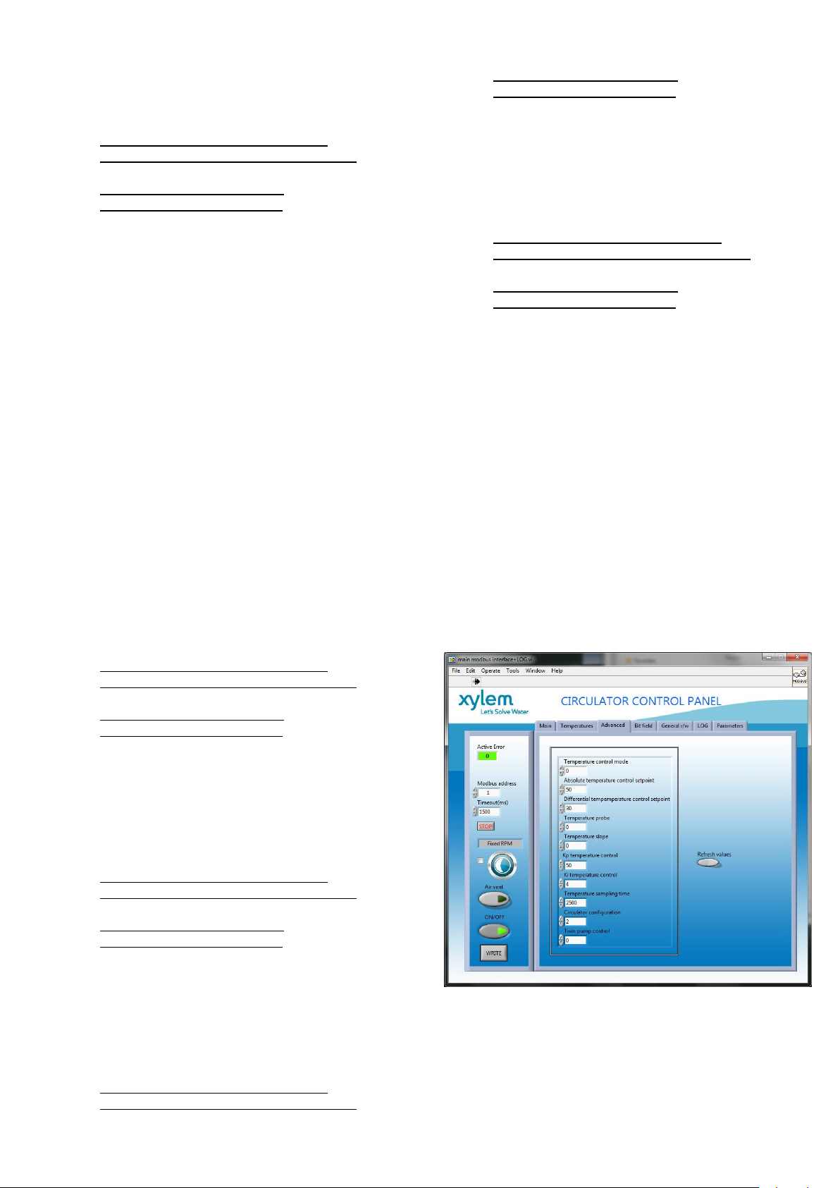
6.1.3 Water Temperature dependent
Control Modes – Circulator Control
Panel
In order to configure the desired Temperaturedependent control mode using Circulator Control
Panel, refer to the Advanced Tab
6.1.3.1 Advanced Tab
Collects two subset of parameters:
The subset used for advanced settings, as
described in this technical sheet at par. 8.2.1.2
The subset used for twin pump settings, as
described in this technical sheet at par. 8.2.1.3
Page 18

6.2 Wireless Module
Referring to Figure 12, once the module is connected,
is necessary to configure it by setting the parameter
“Module” to the value “Wireless”, as described in par.
4.3.5.2.
6.2.1 Wireless module use
When the wireless module is assembled into ecocirc
XLplus, and correctly configured, it generates a (type
902.11n) wireless network accessible (by a mobile,
tablet or a PC) using data (S/N and PWD) printed on
the label sticked on the side of the circulator’s drive
In particular,
Network name: “ecocircxl___S/N___” where
S/N is a 8 character word
Password: “xylem___PWD___” where PWD is
a 8 character word
To access then the circulator’s web pages using a
browser (on the external device connected), use the
web address “https://xylemecoxl” or type directly
“192.168.1.10”
6.3 RS485 Module
Referring to Figure 12, once the module is connected,
is necessary to configure it by setting the parameter
“Module” to the value “RS485”, as described in par.
4.3.5.2
Page 19
7 Appendix 1
Figure 4
Figure 5
Page 20

1
2
3
L
N
10 A
Figure 6
Figure 7
Page 21

4
5
7 8 9
11
12
13 14
16
17
18 19 20
21
P+
S+T+ T- S-
B A
G
N
D
P-
C
NO
Start / Stop
B
A
10
L N
C NO S+ P+ P- T+ T-15V B A GND B AS- GND
Start / Stop
Figure 8
Figure 9
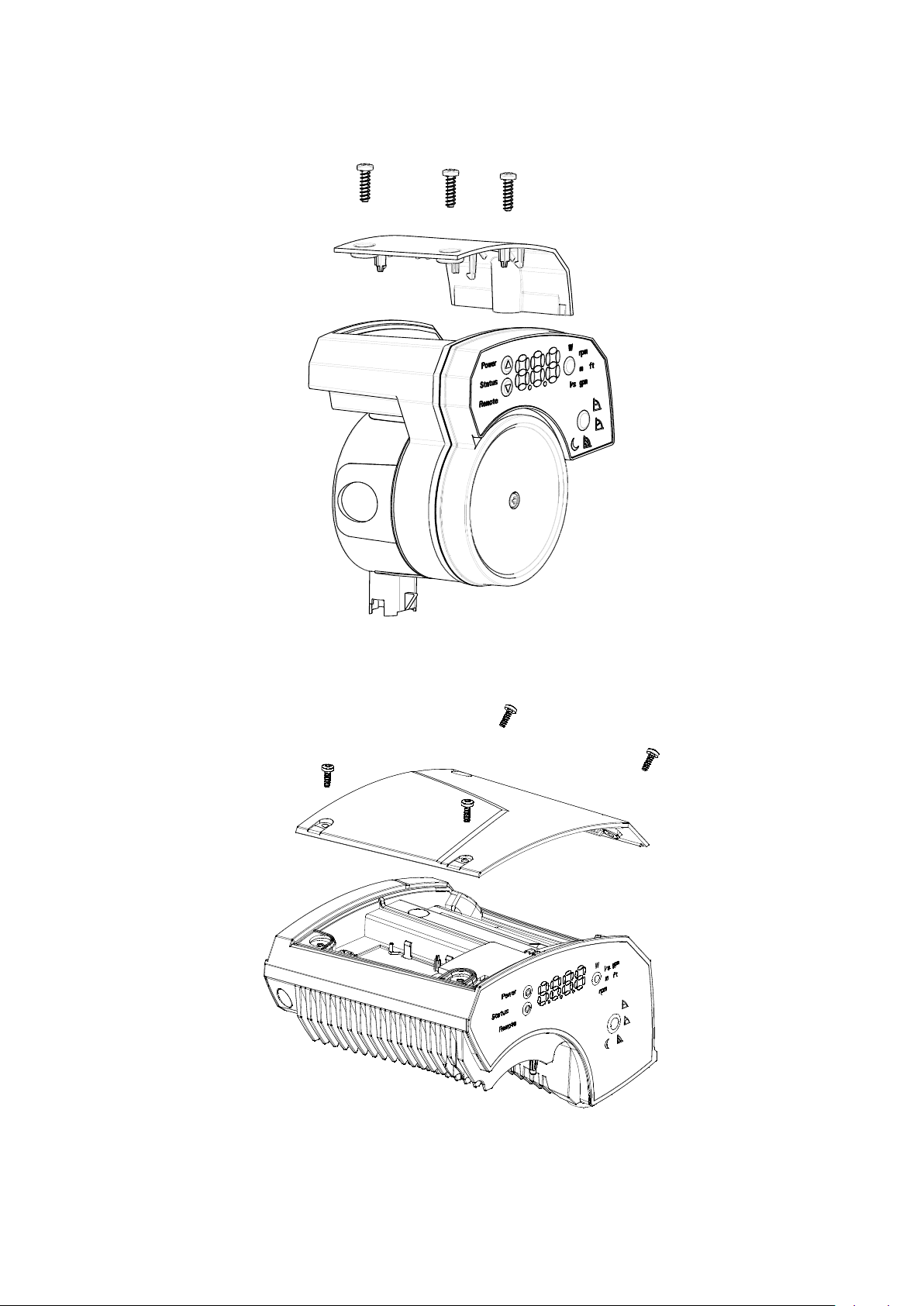
Page 22

Figure 10
Figure 11
Figure 12
Page 23

MB. ADDRESS
(HEX)
PARAMETER DESCRIPTION
0x0000
OPERATING MODE
0 = OFF
1 = ON
0x0001
CONTROL MODE
1 = CONSTANT PRESSURE
2 = PROPORTIONAL PRESSURE
3 = CONSTANT CURVE
0x0002
NIGHT-MODE ACTIVATION
0 = NOT ACTIVE
1 = ACTIVE
0x0003
AIR VENTING PROCEDURE
0 = NOT ACTIVE
1 = ACTIVE
0x0004
PROPORTIONAL PRESSURE SETPOINT
(for CONTROL MODE = 2)
0x0005
CONSTANT PRESSURE SETPOINT
(for CONTROL MODE = 1)
0x0006
CONSTANT CURVE SETPOINT
(for CONTROL MODE = 3)
0x0007
AIR VENTING POWER ON
0 = NOT ACTIVE
1 = ACTIVE
MB. ADDRESS
(HEX)
PARAMETER DESCRIPTION
0x0030
TEMPERATURE CONTROL MODE
0 = NOT ACTIVE
1 = PROP. TEMPERATURE TO HEAD
2 = CONSTANT TEMPERATURE
0x0031
ABSOLUTE TEMPERATURE SETPOINT
0x0032
DIFFERENTIAL TEMPERATURE SETPOINT
0x0033
TEMPERATURE PROBE
0 = INTERNAL
1 = EXTERNAL
2 = DIFFERENTIAL
0x0034
TEMPERATURE SLOPE
0 = INCREASING
1 = DECREASING
0x0035
KP FOR TEMPERATURE CONTROL
0x0036
KI FOR TEMPERATURE CONTROL
0x0037
TEMPERATURE CONTROL SAMPLING TIME
MB. ADDRESS
(HEX)
INFORMATION DESCRIPTION
0x0200
INPUT POWER
0x0201
HEAD [H]
0x0202
FLOW [Q]
0x0203
SPEED
0x0204
WATER TEMPERATURE
MB. ADDRESS
(HEX)
PARAMETER DESCRIPTION
0x0060
CIRCULATOR CONFIGURATION
0 = TWIN MASTER
1 = TWIN SLAVE
2 = SINGLE
0x0061
TWIN PUMPS CONTROL MODE
0 = BACKUP
1 = ALTERNATE
2 = PARALLEL
8 Appendix 2 – Modbus
registers
8.1 Data Organization
The drive offers the below Modbus Virtual Memory
(see par. 8.2), based on a data set that can be divided
into 2 main subsets:
Parameters, that is “Readable and Writable”
data [R/W] used for setting a specific
behaviour, activating a function, writing data,
etc. inside the drive.
Information, that is “Readable” data [R], used
for acquiring values or feedbacks from the
drive
8.2 Modbus Virtual Memory
The complete data-set managed by the ecocirc XLplus
is accessible considering a Modbus Virtual Memory
made exclusively of Holding Registers, representing
both Parameters and Information: readable and
writable the Parameters, readable only the Information.
For a detailed description of the Modbus Virtual
Memory organization, refer to the related document
“ecocircXL - Modbus Parameters Table”.
8.2.1 Parameters Tables
8.2.1.1 Parameters Table 1
It is a set of parameters [R/W] used for standard
settings: generally the same operations or functions a
user can perform/activate through the user interface.
8.2.1.2 Parameters Table 2
It is a set of parameters [R/W] used for advanced
settings: these operations or functions cannot be
performed/activated through the user interface
8.2.1.3 Parameters Table 3
It is a set of parameters [R/W] used for twin pump
settings.
8.2.2 Information Tables
8.2.2.1 Information Table 1
It is a set of information [R] used for standard use:
generally the same data a user can acquire through
the user interface
Page 24

0x0205
EXTERNAL WATER TEMPERATURE
0x0206
WINDING 1 TEMPERATURE
0x0207
WINDING 2 TEMPERATURE
0x0208
WINDING 3 TEMPERATURE
0x0209
POWER MODULE TEMPERATURE
0x020A
QUADRATURE CURRENT
0x020B
BIT FIELDS STATUS I/O
0x020C
BIT FIELDS ALARM 1
0x020D
BIT FIELDS ALARM 2
0x020E
BIT FIELDS ERRORS
0x020F
ACTIVE ERROR CODE
MB. ADDRESS
(HEX)
INFORMATION DESCRIPTION
0x0230
MODBUS SLAVE ADDRESS
0x0231
WI-FI CLIENT/SERVER CONFIGURATION
0 = SERVER
1 = CLIENT
0x0232
PRESSURE SENSOR MODEL
0 = DIFF. PRESSURE SENSOR / Range 0 ÷ 1.0bar
1 = DIFF. PRESSURE SENSOR / Range 0 ÷ 2.0bar
0x0233
PROPORTIONAL PRESSURE MIN SETPOINT
0x0234
PROPORTIONAL PRESSURE MAX SETPOINT
0x0235
CONSTANT PRESSURE MIN SETPOINT
0x0236
CONSTANT PRESSURE MAX SETPOINT
0x0237
CONSTANT CURVE MIN SETPOINT
0x0238
CONSTANT CURVE MAX SETPOINT
0x0239
COMMUNICATION PROTOCOL
0 = MODBUS
1 = BACNET
0x023A
BAUD RATE
MB. ADDRESS
(HEX)
INFORMATION DESCRIPTION
0x0260
TWIN SLAVE DRIVEN CURVE
0x0261
TWIN SLAVE START/STOP
0 = STOP
1 = START
0x0262
TWIN SLAVE INPUT POWER
0x0263
TWIN SLAVE HEAD [H]
0x0264
TWIN SLAVE FLOW [Q]
0x0265
TWIN SLAVE SPEED
0x0266
TWIN SLAVE WINDING 1 TEMPERATURE
0x0267
TWIN SLAVE WINDING 2 TEMPERATURE
0x0268
TWIN SLAVE WINDING 3 TEMPERATURE
0x0269
TWIN SLAVE POWER MODULE TEMPERATURE
0x026A
TWIN SLAVE QUADRATURE CURRENT
0x026B
TWIN SLAVE BIT FIELDS ALARM 1
0x026C
TWIN SLAVE BIT FIELDS ALARM 2
0x026D
TWIN SLAVE BIT FIELDS ERRORS
8.2.2.2 Information Table 2
It is a set of information [R] used for advanced use:
generally these data cannot be accessed through the
user interface.
8.2.2.3 Information Table 3
It is a set of information [R] used for twin pump use:
generally these data cannot be accessed through the
user interface, and are available to the Twin Master for
managing the pump: in fact this table is visible only in
case the drive is configured as a Twin Pump Master
(see par. 4.3.5.1)
Page 25

1
Xylem Service Italia s.r.l.
Via Vittorio Lombardi, 14
Montecchio Maggiore VI
36075
Italy
Tel: (+39) 0444 707111
Fax: (+39) 0444 492166 ©2013 Xylem Inc.
 Loading...