

Page 1
R
INSTRUCTIONS
INSTRUCTIONS
BEDIENUNGSANLEITUNG
BEDIENUNGSANLEITUNG
VZ-27plus / VZ-57plus
VZ-27plus / VZ-57plus
ENGLISH / DEUTSCH
Check out our Internet Homepage for additional information
www.wolfvision.com/support
Page 2
Precautions
ENGLISH
WARNING!
Risk of electric shock
Dangerous voltage inside
Please follow these precautions:
USE THIS MACHINE ONLY WITH THE CORRECT VOLTAGE AS SHOWN ON THE TYPE LABEL !
DO NOT EXPOSE THE UNIT TO EXTREME HEAT OR MOISTURE !
DO NOT CARRY THE VISUALIZER HOLDING IT ONLY BY ITS MIRROR ARM (#1) !
PROTECT THE UNIT FROM EXCESSIVE SHOCKS !
Make sure that sufficient air circulation for cooling the unit is possible (ventilation slots on the left and
right side of the unit)!
If there is any abnormality (abnormal noise, smell, smoke etc.) disconnect the unit from mains immediately
and contact your Visualizer dealer!
Do not use a damaged power cord.
This may cause short circuits or electrical shocks!
Do not modify the Visualizer or operate it without the cover panel firmly in place, to prevent danger!
Do not expose the Visualizer to water, metallic objects or any flammable material.
Avoid installing the Visualizer in environments where there is radiation.
Avoid installing the Visualizer in locations exposed to strong magnetic fields or electrical currents. This
could cause monitor image distortion or damage to the CCD camera.
If the Visualizer is not used for a long time, disconnect it from mains!
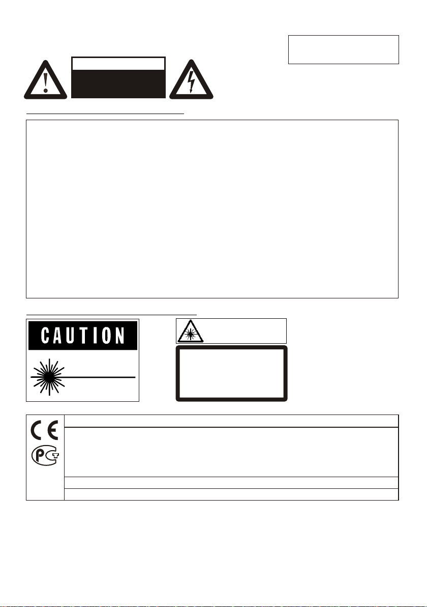
Precautions for built-in laser pointer:
AVOID EXPOSURE -
Laser radiation is emitted
LASER RADIATION - DO NOT
STARE INTO BEAM
650nm, P<1mW
CLASS II LASER PRODUCT
from this aperture.
LASER RADIATION
DO NOT STARE INTO BEAM
CLASS 2 LASER PRODUCT
OUTPUT POWER <1mW
WAVELENGTH 650nm
EN 60825-1 March 1997
FDA accession
number:
9912688-00
This device
complies with
21 CFR 1040.10
and 1040.11
This product is built according to Directive EMC and to Directive electrical equipment.
This equipment has been tested and found to comply with the limits for a Class B digital device, pursuant to Part
15 of the FCC Rules. These limits are designed to provide reasonable protection against harmful interference when
the equipment is operated in a commercial environment. This equipment generates, uses, and can radiate radio
frequency energy and, if not installed and used in accordance with the instruction manual, may cause harmful
interference to radio communications. Operation of this equipment in a residential area is likely to cause harmful
interference in which case the user will be required to correct the interference at his own expense.
Inspections, tests and evaluation according to UL 60950. CSA 22.22-60950
Inspections, tests and evaluation according the CB-Scheme
The professional WolfVision Visualizer system was developed and designed by WolfVision in Austria.
Patents (examples): US 5027219, FRG 3833908, CH 678576.
Printed in Austria, September 2005 Design and specifications subject to change!
1
Page 3
3
1
6
10
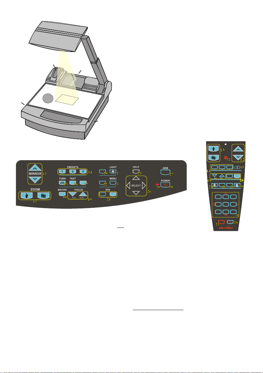
#1 Arm
#2 Base mirror
#3 Top mirror (sensing head)
#4 Control panel
#5 Synchronized lightfield (top light)
#6 Remote Control
#7 Ventilation, air outlet
2
#8 Ventilation, air inlet
#9 Working surface with built-in
7
11
5
9
4
8
Bottom light (removable)
#10 Connectors on the back
(see page 11, 12)
#11 Lamp exchange cover
under the removable bottom light
(see page 10)
CONTROL PANEL:
EXT/INT
FREEZE
A
A
AF
#12 Upper MIRROR up and down (for scrolling)
(Can also be moved by hand! This does not
cause any harm to the motor of this mirror!)
#13 ZOOM keys
#14 Three user programmable PRESETS
(see page 7)
#15 IMAGE TURN key (see page 6)
#16 TEXT Enhancement key improves the
contrast for better readability (see page 7)
#17 FREEZE key to freeze the current image
(see page 7)
#18 MACRO
For bigger enlargements (see page 5)
#19 Manual FOCUS adjustment (see page 5)
#20 EXT / INT switches between Visualizer
image and external input (see page 8)
#21 LIGHT switches between "Top light",
"Bottom light" and "Light off"
#22 WHITE activates one push
WHITE BALANCE adjustment (see page 7)
#23 MENU activates the on-screen menu
(see page 9)
WHITE
ZOOM MIRROR
LASER
PRESETS
IMAGE TURN
A
2 3
REMOTE
CONTROL:
1
FOCUS IRIS
AF
LIGHT
1
4
7
A
EXT / INT
ALLTEXT
MEMORY
3
2
HELP
5
6
9
8
POWER
MENU
#24 Manual IRIS makes image brighter or darker
(see page 5)
#25 HELP activates the on-screen help for the
on-screen menu. This key is only available
after pressing the MENU key (#23) for 1 sec.
#26 SELECT keys for on-screen menu (only
available after pressing the MENU key (#23)
for 1 sec.)
#27 Motorized ARM up and down
#28 (Standby) POWER on and off
#29 Power indication LED (red=off, green=on)
Only on remote control:
#30 ALL-key for displaying all 9 pictures of the
memory as split image (see page 8)
#31 MEMORY keys 1-9 (see page 8)
#32 LASER pointer key
Important: Do not stare directly into the beam.
This would be bad for your eyes!
2
Page 4

HOW THE VISUALIZER WORKS
f
a) light projector
b) camera
c) light path
d) image path
e) base mirror
f) top mirror
g) pickup area /
synchronized
lightfield
c
d
e
g
a
b
BASIC PREPARATIONS
A light projector (a) inside the unit projects a
lightfield (g) the same size as the pick-up
area of the built-in camera via the base mirror
(e) and the top mirror (f) onto the working
surface. The image is recorded by the camera
(b) using the same path.
The lenses of the light projector (a) and the
camera (b) are synchronized. Thus the size of
the light field on the working surface changes
when the user changes the zoom range of the
camera.
This scanning and illumination system is a
worldwide patent from WolfVision.
1. Connect the power cable to the unit (#35) and plug it in.
2. If you would like to use a control monitor, connect it to the following outputs:
Computer monitors: Preview RGB output (#39)
Video monitors: Y/C (S-Video) output (#43) or Composite Video output (#44).
3. Connect a large viewing monitor or a projector to one of the outputs of the Visualizer.
For choosing the right output please read page 11 and 12!
4. Turn the main power switch (#33, on the back of the unit) to "I". The red power indicator
(#29) on the control panel indicates that power is supplied.
5. If the arm is folded down press the ARM-key (#27) on the control panel, then the arm
comes up automatically.
6. Press the POWER-key (#28) on the control panel.
The Visualizer now runs the "power-on preset" (=automatic focusing of an A5 format on
the working surface) during which the green LED light (#29) is flashing. As soon as
the green LED light stays illuminated you can start working with the Visualizer.
(The behaviour of the unit once that power is supplied to the unit or after the POWER-
key is pressed can be changed in the unit's menu - see page 9 and on-screen help)
3
Page 5
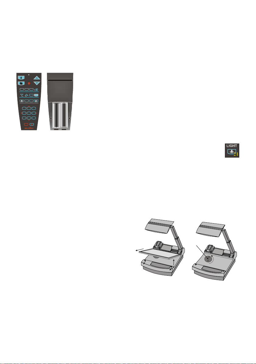
WORKING ON THE WORKING SURFACE
1. Place your subject material on the working surface.
A synchronized lightfield on the working surface marks the pick-up area
of the built-in camera! Just place your subject material in the illuminated
area.
2. Select the enlargement required with the ZOOM-keys (#13).
3. Use the MIRROR-keys (#12) on the control panel or the remote control to
change the vertical position of the pick-up area. The upper mirror can also
be moved by hand! This does not cause any harm to the motor of this
mirror!
DO NOT TOUCH THE MIRROR SURFACE, AS FINGERPRINTS
Synchronized
lightfield
CAUSE BRIGHT AND HAZY SPOTS ON THE PICTURE ! ALWAYS
KEEP THE MIRROR CLEAN ! - see page 13
CAUTION: SENSITIVE FRONT COATED MIRROR!
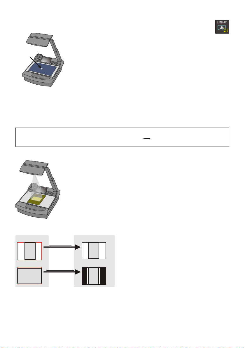
SYNCHRONIZED LIGHTFIELD
If the top light of the Visualizer is used (normal working condition) a synchronized lightfield
always marks the pick-up area of the built-in camera on the working surface.
The alignment of this lightfield is made for working on the working surface. Because of the oblique
mounting of the camera and the light projector of the Visualizer the lightfield shifts to the left when the
distance between the Visualizer and the scanned object is increased (when capturing images outside
of the working surface). This means that the lightfield no longer exactly shows the recorded area. In this
case switch off the Visualizer’s top light with the LIGHT-key (#21) and work with room light.
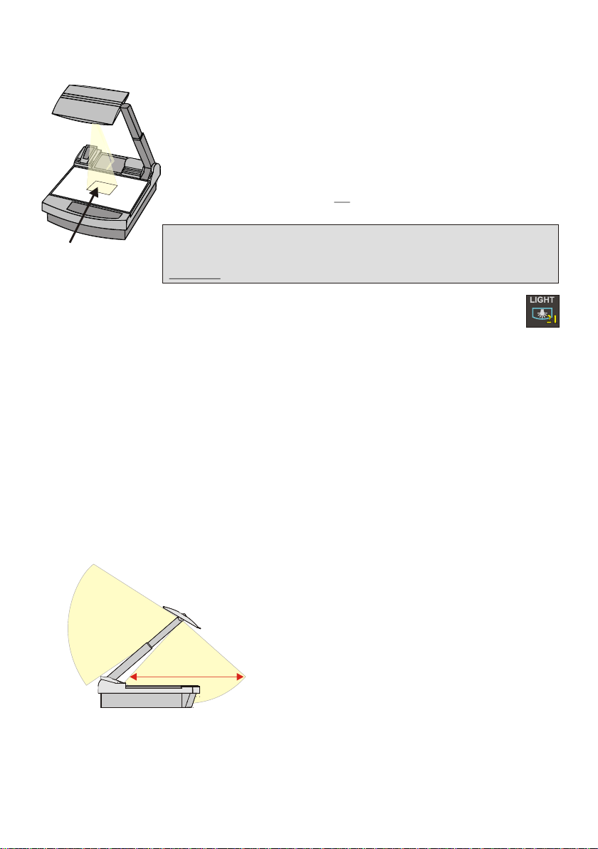
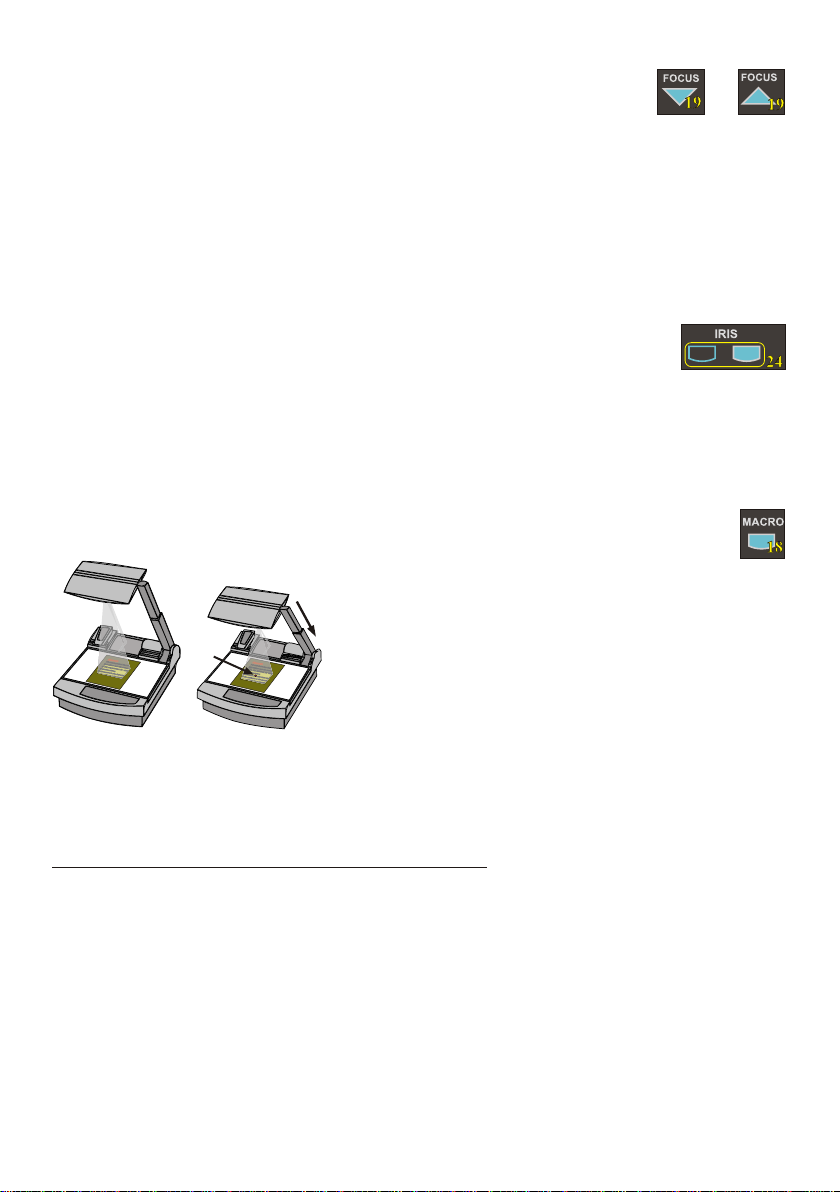
WORKING OUTSIDE THE WORKING SURFACE
For showing 3-dimensional objects with the WolfVision Visualizer, just place them on the working
surface and adjust ZOOM and FOCUS (as mentioned). Due to a special WolfVision lens the object can
be up to 25 cm (9.7") in height. If the object is to big for the working surface or if you want to show it
from the side just place it behind or in front of the unit and tilt the top mirror by hand or using the
MIRROR-keys (#12).
In this way it is also possible to make
recordings of objects in the room or
surrounding area, just like with a video
camera.
to infinity
700mm (27.6")
Due to the great focal range it is possible to
show details in every distance to the unit.
If you want to record people you should turn
off the light with the LIGHT-key (#21), so that
they are not blinded by the light.
4
Page 6
FOCUSING
+
When the Visualizer is turned on the focus automatically adjusts to the working
surface level. As a result it is not necessary to readjust the focus if you are only working with flat
material (text, photos etc.). Furthermore, due to the great depth of focus of the Visualizer it is rarely
necessary to readjust the focus.
Only very high objects require a focus adjustment.
Pressing both FOCUS-keys (#19) simultaneously, activates a One-Push Auto focus.
(Please note that this is a new function, introduced in Mai 2005 with firmware Version 1.13a.
Units with older firmware perform an Auto focus for flat objects with this key combination.)
AUTO IRIS / MANUAL IRIS
WolfVision Visualizers are equipped with auto-iris. That means that the brightness of
the camera image adjusts automatically. Using the IRIS-keys (#24) the auto iris function is switched off.
In this mode the Iris can be adjusted manually.
When using the ZOOM-keys (#13) the auto iris function is switched on again. Before the iris closes
completely, the Visualizer automatically dims the light.
The standard auto iris level can be set brighter or darker in the unit's menu
- see page 9 and on-screen help.
MACRO MODE / 4x DIGITAL ZOOM
In the fully extended position of the arm, the smallest pick-up
area is 42 x 33mm (1.6" x 1.3").
Laser
center
P
l
ea
s no
e
e:
t
I
tisv im antth
e
r
y p
o
rt
l
i
gh
t so
s
h
a
i
n
e
n
a
t h
o
s ti
t
e
sm
c
s
e
ree
a
yin
t
p
rfe
r
o
j
r h
e t
c i
t
i
o
e
n
p
v
ideoh
c r
t
Fu h
u
e
t
.e
e
r o
m e
r i
t
tatth
i o
s a
ls
e
i
m
a
uienc o
por
d
t
an
d ot
o n
e
tr
r h
t p
g
e
es e e
t b
lin
ak
d
n
e
d r
db a
a
rh
y
a
rk
brigh li
om i
o
t h
.
g
t
marker
t t
n
os
r
ay
n
,
Pl
ea
se note:
It is
very import
lig
ant that no
ht s
hine
s
st
onto t
ra
as
th
h
e screen
is
may
in
,
te
proj
rfer
ec
e
tion pi
the
video
ct
Fu
ure.
rt
he
rm
ore it
th
is
at
a
lso import
th a
e
ud
ie
nc
ant
o
e
n
or
ot
th
get b
e
sp
lin
eaker
ded by a
in a d
ar
k room
b
right
.
lgh
id
t
When pressing the MACRO-key (#18) the length of the arm is
automatically reduced, this allows greater enlargements. In the
y
macro mode the smallest pick-up area with full optical
resolution is: 30 x 22mm (1.2" x 0.9"). When zooming in, the
zoom stops at this size.
If you press the ZOOM IN-key again after the stop, the unit activates its digital zoom extension. In this
mode you can zoom into a picture as small as 8 x 6mm (0.3" x 0.2”).
Please note that the resolution in the digital zoom area is lower!
The MACRO-key is illuminated in red color if the macro function is activated.
Please note that the macro mode has the following limitations:
- The depth of focus and the object height that can be focused is not as large as in the fully
extended arm position.
- The largest pick-up size is only about 42 x 33 mm (1.6" x 1.3").
- When zooming the Synchronized Lightfield stays at a larger size and no longer marks the pick-up
area of the built-in camera. The Laser Center Marker (see next chapter) is activated as a substitute.
If sufficient depth of focus and focusing high objects in the macro mode is more important than big
enlargements, it is possible to switch the Visualizer from 12x zoom to 11x zoom in the Visualizer's
menu (see page 9). The smallest pick-up size in the 11x macro mode is only 33 x 25mm (1.3" x 1"), but
the depth of focus is larger than in the 12x macro mode.
5
Page 7
BOTTOM LIGHT / LASER CENTER MARKER
The LIGHT-key (#21) can be used to switch between:
"Top light" (with Synchronized Lightfield)
"Bottom light" with Laser Center Marker
Laser
center
marker
"Light off"
The bottom light should be used for dark transparent materials such as x-
rays or for very small transparent material such as slides.
Using the bottom light has the disadvantage that the Synchronized Lightfield
of the top light no longer marks the pick-up area of the built-in camera.
However as a substitute the Visualizer has a built-in Laser Center Marker,
which marks the center of the pick-up area. This can also be used for
positioning of objects (especially with big enlargements, like when picking
up a slide).
The Laser Center Marker is only visible on the working surface and NOT on the picture the audience
sees. For safety reasons the Laser Center Marker is automatically switched off when the top mirror is
tilted to record outside of the working surface. If required the Laser Center Marker can also be switched
off completely in the unit's menu (see page 9 and on-screen help menu).
Please note that for technical (optical) reasons the laser center marker can not show the exact middle
center of the pickup area in every position of the arm. This is not a failure of the unit! However it is
always very close to the center.
WORKING WITH TRANSPARENCIES
The working surface of the Visualizer (#9) has a special crystalline white color,
which is especially designed for perfect reproduction of transparencies.
Even though the professional Visualizers have a built-in bottom light it is
recommended to use the top light for transparencies, because of the better
color reproduction and the advantage that the Synchronized Lightfield still
P
le
ase note
:
It
i
s v
ery im
p
o
rtan
light
t tha
sh
in
t
no s
es
on
tr
as t
to th
ay
his
e
screen,
ma
y in
terfe
projec
re
t
ti
he video
on pictu
F
ur
re.
th
ermore
it
th
is a
at th
lso
e audience or
i
mporta
do
n
t
not get
th
e speaker
bli
n
ded by
in a
dark
a b
r
rig
oom.
ht
li
ght
shows the pickup-area of the built-in camera.
However in these situations it is recommended to use the bottom light:
- If the transparency is very dark
- If the transparency is very wavy and causes reflections
- If the room light causes reflections on a transparency
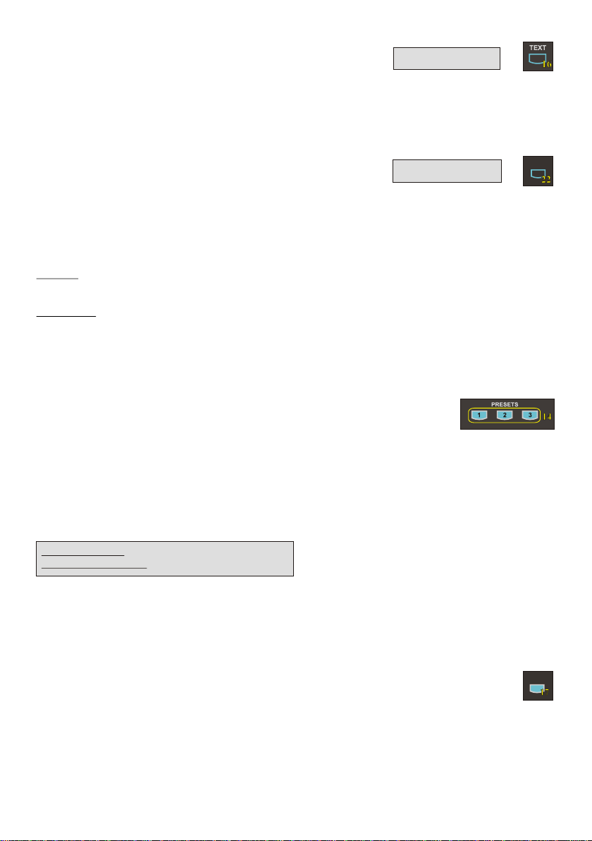
IMAGE TURN MODE (for higher resolution)
Working surface:
Normal mode:
A
Only 50% of the
pixels are used to
pick up the document
Image turn mode:
90% of the pixels
A
are used to pick
up the document
Just place your document (or other vertical object)º on the working surface horizontally and zoom in on it
completely, so that about 90% of the pixels of the built-in camera are used to pick up the document.
Then press the IMAGE TURN-key (#15) one time. The Visualizer turns the picture electronically 90
and outputs it the right way up with a much higher resolution than in normal mode. The left and right
margins are black.
The IMAGE TURN-key (#15) can also be used to rotate the image 90, 180 and 270 degrees.
Each time this key is pressed, the image rotates 90 degrees.
Output picture:
A
A
Picking up a complete vertical (portrait) document or
A4 page has always been a critical issue for a
Visualizer, because the image is always picked up in
a horizontal (landscape) format.
The camera could only use 50% of its pixels to pick
up a vertical (portrait) page. WolfVision's Image turn
mode solves this problem.
6
Page 8
TEXT ENHANCEMENT
For improving the readability of text, sketches and x-rays press the TEXT-key (#16). This mode
enhances the contrast of the picture. Please note that in this mode the colors are darker than usual. To
switch off the text enhancement mode press the TEXT-key again.
While the text mode is activated the TEXT-key on the control panel is illuminated red.
IMPORTANT
WHITE BALANCE ADJUSTMENT
Each time the lighting condition changes, the user should adjust the white balance of the Visualizer's
camera, in order to optimize the color reproduction. The Visualizer's top- and bottom-light have the
same color temperature so normally a new white balance adjustment is not necessary when changing
from one light to the other, but if there is also room light or sun light shining on the working surface,
the white balance should be adjusted.
Top light: First, zoom in on a white object (for example a white paper) until there is only white on the
screen. Then press the WHITE-key (#22).
Bottom light: Turn on the bottom light with the LIGHT-key (#21). Remove everything from the working
surface. Zoom to the smallest picture. Then press the WHITE-key (#22).
You can adjust the white balance either for the top or for the bottom light and it works well with both
lights. When the white balance adjustment is finished successfully the message "WHITE OK" appears
on the monitor after a few seconds. The new white balance is stored automatically and is preserved
even if the power supply is interrupted.
IMPORTANT
WHITE
PRESET FUNCTION
WolfVision Visualizers offer the possibility of programming three presets for the functions: Zoom,
Focus, Iris, Light, Text, Macro, White Balance, Mirror position*, Positive/Negative and Black/White.
They can be recalled by pressing one of the three PRESET-keys (#14) on the control panel or the
remote control.
.
This function is very useful for example if a user requires one preset for papers on the working surface,
one for working with slides (bottom light) and one for an object placed in front of the unit. During his
presentation the user just has to press one of the PRESET-keys when he changes from one object to
Quickly pressing: Recalling a preset
More than 2 seconds: Saving a new preset
* You can select in the unit's on-screen menu if
the mirror position should be stored in a
preset or not (see page 9). Default is: YES.
For programming a preset just adjust every function as required and then keep one of the PRESET
keys pressed for more than 2 seconds. The on-screen menu tells you when the preset is stored.
When the presets are stored as mentioned above, all current settings like zoom-, focus- or mirrorposition are stored. Contrary to this, a user also has the opportunity to assign only specific functions
such as "Freeze", "Iris open/close", "Negative", "Negative/Blue", "Black/White" etc. to a PRESET-key.
This can be done in the on-screen menu of the Visualizer (see page 9).
FREEZE
The current image can be frozen by pressing the FREEZE-key 7 .
The FREEZE-key is red illuminated if the freeze function is activated. The FREEZE-key also works as
image memory key if pressed for 2 seconds (see page 8).
The behavior of the FREEZE-key can be changed in the on-screen menu (see page 9).
7
(#1 )
FREEZE
Page 9
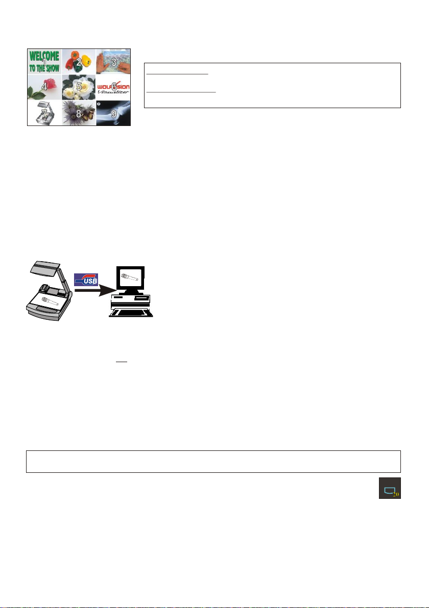
9-IMAGE MEMORY
You can store 9 images and recall them by just pressing one of the
numerical keys (#31) on the infrared remote control:
Storing an image: Press one of the MEMORY-keys (#31)
for more than 2 seconds
Recalling an image: Press one of the MEMORY-keys (#31)
quickly
By pressing the ALL-key (#30) a split image with all 9 pictures of the
Split image of 9 picture memory
memory can be displayed.
When pressing the ALL-key (#30) for 4 seconds, a menu appears on the screen asking if you would
like to erase all stored pictures (black picture) or if you would like to fill the memory with “snapshots”.
When choosing “snapshot” the Visualizer stores a new image every second until the 9 memory
locations are full.
The Visualizer is equipped with a memory backup battery. It stores the pictures in the memory when the
power supply is disconnected for up to 4 weeks. Images can also be stored by pressing the FREEZEkey (#17) for 2 seconds. The image will be stored in the next available memory (1-9). If the memory is
full, an on-screen message will appear.
The functional settings of the memory feature can be changed in the on-screen menu (see page 9).
USB-PORT
The USB 2.0 port of the Visualizer can be used to capture and
transfer Visualizer images onto a computer.
HI-SPEED
CERTIFIED
TM
In this way the Visualizer can be used as a scanner for
3-dimensional objects for your computer. Just connect the USB
port (#37) of the Visualizer to the USB port of your computer, using
the supplied USB cable. The software is fully Twain compatible.
The USB 2.0 output of the Visualizer is fully USB 1.1 compatible
(less speed with USB 1.1).
The WolfVision USB-software can be found on the supplied CD-ROM. Please check our Internet
homepage at: www.wolfvision.com/support if an update of this software is available as a freedownload. The software works under Windows 98/ME/2000/XP and MAC OS10 (or later).
Windows 95 and NT will not work, because they do not support USB.
ETHERNET / LAN
The LAN connection (10BASE-T/100BASE-TX) can be used for controlling the Visualizer over a
computer network, image transfers and firmware updates.
The following protocols are supported: TCP/IP, ICMP and ARP.
Standard settings (changeable): IP-address and Subnet-mask from DHCP-Server
Image Transfer Resolution: Still Image: 1024x768 (or 512x384), Live Image: 160x120
Please check the special ETHERNET/LAN manual on our homepage at:
www.wolfvision.com/support.
EXTERNAL INPUT / SCALER
A Computer can be connected to the External RGB input (#41) of the Visualizer.
By pressing the EXT/INT-key (#20), you can switch between the Visualizer image and the image of the
external input to displayed to the audience.
The extern mode can also be used for only one output. The behavior can be changed in the on-screen
menu (see page 9). The Visualizer has a built-in scaler (A/D-converter) in order to digitize the analog
RGB signal from the computer and output it on all outputs in the selected format (allowed signals: from
VGA to SXGA/75Hz). As the built-in scaler allows the image from the external input to be output on the
PAL/NTSC video outputs, the Visualizer can also be used as a computer to video image converter.
:Supported Browsers are Internet Explorer, Netscape Navigator and Mozilla.
EXT/INT
8
Page 10

ON-SCREEN MENU / ON-SCREEN HELP
For standard use of the WolfVision Visualizer it is not necessary to enter the on-screen menu
of the Visualizer and change settings. Inexperienced users should not make any adjustments here.
To enter the on-screen menu press the MENU-key (#23) for one second. Settings of the Visualizer's
basic functions and the built-in camera can be made here using the 4 select keys (#26, = the numerical
keys with red arrows on the remote control - #31).
Please note that some basic settings in the menu can only be changed if you set the menu item
"Format protect" to "OFF" first.
If more information on a function in the on-screen menu is required just set the cursor in the respective
line and press the HELP key (#25, or the Number 5 key #31, this key has a double function). A detailed
description of this function appears on the screen. If you want to reset the selected item to the default
setting, just press the HELP key (#25, or Number 5 key #31) for 2 seconds!
The functions of the on-screen menu are not described in detail in this user manual as the help menu is
an integrated part of the Visualizer's software (firmware). The information you see on your screen
always belongs to the current Visualizer firmware.
SWITCHING to NEGATIVE, NEGATIVE/BLUE and BLACK/WHITE
The output image of the Visualizers can be switched from positive to negative in the on-screen menu.
In addition, the background of a negative image can be switched to blue for better readability of text.
You can also switch between color and black/white in the on-screen menu.
TIP: If you often switch to negative, negative/blue or black/white images you can assign this function to
one of the PRESET-keys (#14) in the on-screen menu (see page 7).
CHANGING THE STANDARD CONTRAST (color) SETTINGS
If the picture or the colors on your screen appear to be too dark, you can lower the overall contrast of
the picture in the "Color settings" menu of the on-screen menu. The settings can be made separately
for the normal mode and the text-mode.
AUTO POWER OFF
In the "Power control" settings in the on-screen menu you can select that the Visualizer will be
automatically switched off, if not used for a certain amount of time.
RESET of ON-SCREEN MENU SETTINGS
All settings in the on-screen menu can be set back to the factory defaults. "Reset" is one item in the onscreen menu. In case you can not read the menu on a screen you can also set the unit back to the
factory defaults by simultaneously pressing the EXT/INT-keys (#20) and the MENU-key (#23) on the
unit.
If you only want to reset a currently selected item to the default setting, press the Help-key (#25, or
Number 5-key on the remote control #31) for 2 seconds!
FIRMWARE UPGRADES
The software (firmware) of your Visualizer (including the o ) can easily be upgraded to
the latest version.
First download the latest firmware and WolfVision's firmware update utility program from Wolfvision's
internet homepage at www.wolfvision.com/support.
Then connect the Visualizer to your computer and run the firmware update utility program. More details
on the firmware updates can be found on WolfVision's internet homepage.
The firmware update can be done via USB, Ethernet (LAN) or RS232.
n-screen HELP
9
Page 11
INFRARED REMOTE CONTROL
Please note that an infrared remote control can only be used up to a certain distance from the unit.
Objects situated between the Visualizer and the infrared remote control, and weak batteries, interfere
with the reception. If the Visualizer can only be controlled from a close distance, or if it cannot be
controlled at all with the infrared remote control, you may have to change the batteries. Open the cover
on the back of the remote control by hand and replace the two 1.5 V AA batteries with new ones.
Check the polarity of the batteries!
If a user wants to work with a number of WolfVision Visualizers
ZOOM MIRROR
LASER
PRESETS
IMAGE TURN
A
2 3
1
A
FOCUS IRIS
AF
EXT / INT
LIGHT
ALLTEXT
MEMORY
1
3
2
HELP
5
6
4
7
9
8
POWER
MENU
front back (open)
-
X
+
simultaneously, each unit can be set to a different infrared code,
so up to 4 units can be controlled individually with their remote controls.
To change the infrared codes on the Visualizer, enter the
screen menu, by pressing the menu-key (#23) for one second, go
"Misc. Settings" and set the "IR Code" to A, B, C or D (code A is
to
default). To change the infrared code on the remote control,
+
simultaneously press PRESET 1, PRESET 2 and ZOOM TELE
(#13) - each time this key combination is used, the code switches from A
X
to B, C, D ... A ...etc. For resetting the remote control to code A
-
simultaneously p .
ress PRESET 1, PRESET 2 and ZOOM WIDE
(#14)
The LED shows the selected code (it flashes one-time for code A,
two-times for code B, three-times for code C and four-times for code D)
on-
AUTOMATIC LAMP CHANGER
The Visualizer is fitted with an automatic lamp changer. If one lamp fails, there is no need
to replace it immediately, as the automatic lamp changer automatically switches to the second (spare)
lamp. When the unit changes lamps there is an on-screen message saying: "Changing lamp".
When switching on the unit the Visualizer checks if both lamps are working. If one lamp fails there will
be an on screen message for a couple of seconds displaying "Lamp x blown". This prevents a user
from forgetting to change a defective lamp.
If a lamp is not fully defective but worn out and as a result the light output is quite weak, you can switch
manually to the second lamp by pressing the LIGHT-key (#21) for 2 seconds.
EXCHANGING LAMPS
1. Turn the unit off (#28) and disconnect the
power cord!
2. Remove the bottom light (#9) by pulling the
two spring catches (situated left and right of
Lamp exchange
cover (#11)
the control panel) to the front and lift up the
bottom light plate.
3. Remove the lamp exchange cover (#11)
by turning anti-clockwise and lift it.
4. Change the lamp (or both lamps)
Before changing the lamp allow it to cool or use a cloth to avoid burning a finger! When pressing a new
lamp into the socket use a cloth to prevent fingerprints on the lamp!
Only use 12 V/100 W halogen lamps (socket: GY 6,35), type: Osram HLX 64623,
Ansi EVA, LIF M/28 NAED 54052. These are relatively inexpensive standard OHP lamps.
THERMOSTAT
If the unit gets too hot (improper ventilation or air extraction) a built in thermostat will switch off the light
of the Visualizer. Verify that proper ventilation and air extraction is available and allow the unit to cool.
10
Page 12

CONNECTORS
RGB
40
Video
44
R G B
42
T3,15A
VH
FUSE
34
33
35
EXTERN IN
41
S-VIDEO
43
36
DVI
USB
37
LAN
45
39
PREVIEW
#39 PREVIEW RGB output for control monitor
#40 RGB output 15-pin (see below)
#41 EXTERNAL Input for Computers (see page 8)
#42 RGB output BNC connectors (see below)
#43 PAL/NTSC S-Video (Y/C) output (see page 12)
#44 PAL/NTSC Composite video output (see page 12)
#45 LAN 10/100 TBASE (see page 8)
38
RS-232
#33 Main POWER switch
#34 FUSE (see page 13)
#35 POWER connection
#36 DVI output (see below and page 13)
#37 USB port (see page 8)
#38 RS-232 port for external remote
controlling (see page 13)
Choosing the right output mode
The RGB-, Preview- and DVI-outputs can output a signal in the following formats:
- VGA / 60 (4:3 - 640x480 Pixel) at 60Hz
- SVGA (4:3 - 800x600 Pixel) at 60Hz, 75Hz or 85Hz
- XGA (4:3 - 1024x768 Pixel) at 60Hz, 75Hz or 85Hz - native image
- SXGA- (4:3 - 1280x960) at 60Hz or 85Hz
- SXGA (4:3 - 1280x1024 Pixel) at 60Hz, 75Hz or 85Hz
- SXGA+ (4:3 - 1360x1024) at 60Hz or 75Hz
- UXGA (4:3 - 1600x1200 Pixel) at 60Hz
- XGA 16:9 at 60Hz (special format for not HDTV-capable 16:9-Plasma displays)
- WXGA/60 (16:9 Widescreen - 1366x768 Pixel at 60Hz)
- WSXGA+/60 (16:10 Widescreen - 1680x1050 Pixel at 60Hz)
- 720p/50 (16:9 Widescreen HD/HDTV - 1280x720 Pixel at 50Hz)
- 720p/60 (16:9 Widescreen HD/HDTV - 1280x720 Pixel at 60Hz)
- 1080p/50 (16:9 Widescreen HD/HDTV - 1920x1080 Pixel at 50Hz)
- 1080p/60 (16:9 Widescreen HD/HDTV - 1920x1080 Pixel at 60Hz)
The "Auto Resolution" function is activated by default. In this mode the Visualizer constantly checks
which devices are connected to RGB (#39, 40) and DVI output (#36) and automatically sets the optimal
output mode for each connected device separately.
Please note that the Visualizer can not check the possible resolution, if the connected units or the
cables* are not "Plug and Play" compatible. If the Visualizer can not detect the resolution of the
connected device, the output is set to the default of XGA (1024x768)/60Hz.
(* Cables with plug and play compatibility must have a 15-pin plug on both ends with all pins connected, pin 9 is not used)
If you can not use the “Auto Resolution” function, you can select the output mode manually in the onscreen menu of the Visualizer. Resolution and refresh rate can be adjusted separately for the outputs.
In order to achieve the best picture quality you must set the outputs of the Visualizer to match the native
resolution of your display unit (e.g. LCD or DLP projector or monitor).
Important: What matters is the native resolution of the projector or monitor, not the maximum resolution
that it can display (in compressed mode). The native resolution is the actual number of pixels of the built
in LCD display or DLP chip of a projector or monitor. Most LCD or DLP projectors can also display higher
resolutions than their native resolution, but only in compressed mode and with inferior picture quality. Do
NOT set the output of the Visualizer to a higher standard than the native resolution of your
display unit!
If you output the Visualizer image on a CRT-monitor or CRT-projector, use an output mode with 75Hz or
85Hz, because 60Hz may show a slight image flickering. For LCD/DLP-projectors or -monitors and video
conferencing units 60Hz is the best choice. If you are unsure what is the best mode, check the user
manual of the connected units.
Do not set a higher refresh rate than your monitor or projector can display, otherwise the monitor
or projector can be damaged! Follow the instructions in the user manual of the connected units!
11
Page 13

Special information for Widescreen Support
Widescreen is supported since Firmware Version 1.20a (Older units may need a Firmware
update for Widescreen support).
Please note that WolfVision added widescreen support to the Visualizers in order to assure
100% compatibility with all display units on the market. However the native image ratio of
the Visualizer camera is 4:3. Therefore 25% of the picture (4:3) is cut off when the
Visualizer outputs in 16:9 or 16:10 widescreen format, while the resolution of the image
stays the same.
Upscaling to HD/HDTV does not bring any improvement in resolution. However if you are
using a display device with an aspect ratio of 16:9 or 16:10, the picture quality usually is
better, when the Visualizer scales the image to the widescreen format, and not the display
device. This is because the Visualizer scales the picture at the image source with high end
electronics.
HDTV is developed for digital television. For compatibility, the image can be also output on
the analogue RGB-output (#39, 40 and 42) in HD/HDTV format. The DVI-output (#36) is
HDMI-compatible (A DVI-HDMI adapter or a DVI-HDMI cable can be used).
Please note, if a 4:3 and a 16:9 or 16:10 display is used simultaneously, the 4:3 display
shows black bars on top and bottom (the black bars are also visible on the built-in preview
display). This is necessary to ensure that all displays show the same image content.
Display modes of monitors or projectors (Overview)
(for details please read the user manual of your display unit)
- "Aspect" keeps the original aspect ratio of the picture and will display black bars when
the not-native ratio of the display device is used.
- "Fill" always fills the screen of the display unit and will show a horizontally or vertically
stretched image on display units of the "wrong" format.
- "1:1" the display unit shows the image in the original number of pixels.
Parts which can not be displayed are cut off.
16:9 image on 16:9 display
4:3 image on 16:9 display
with "Fill"display setting
4:3 image on 16:9 display
with display setting "Aspect"
4:3 image on 4:3 display
16:9 image on 4:3 display
with "Fill"display setting
16:9 4:3
image on display
isplay setting "Aspect"
with d
PAL / NTSC VIDEO OUTPUTS
The Y/C (S-video) (#43) and Composite (#44) video outputs can be switched between PAL and NTSC
in the units . e FREEZE- 17
with the Preset 1 (for PAL) or Preset 2 (for NTSC) (# ) key on the .
Please note, that the picture quality of the Y/C (S-video) (#43) output is BETTER than the quality of the
Composite (#44) video output. However t
GOOD as the picture quality of the data outputs
limitations of the PAL/NTSC video system and because of the fact that this is just a converted
Progressive Scan signal and not an original video signal.
on-screen menu Switching can also be done by pressing th key (# ) together
14 unit
he picture quality of both video outputs is BY FAR NOT AS
(#39, 40, 42 and 36). This is because of the
12
Page 14

SERIAL PORT / SERIAL PROTOCOL
The serial port can be used to control the Visualizer through an external device, like a remote control
system for a complete conference room.
3
5
2
4
1
6
7
9
8
9-pin D-Sub connector
on unit, male, front side
A detailed description of the serial protocol (including status report and position setting) can be
downloaded from our website: http://www.wolfvision.com/support.
Pins: 2: RX, 3: TX, 5: GND, 7: RTS, 8: CTS
Baud rate: 9200, 19200, 38400, 57600 or 115200 (selectable)
databits: 8, stopbit: 1, parity: no
Please note: DecimaI-Codes (=ASCII-Codes or Hex-Codes) must be sent as one
single byte (e.g. 199 and not: 1 + 1 + 9) !
DVI PORT
Pin 1
Pin 9
Pin 17
Pin 8
Pin 24
C1
C3
C5
1 - T.M.D.S. Data2- 9 - T.M.D.S. Data1- 17 - T.M.D.S. Data02 - T.M.D.S. Data2+ 10 - T.M.D.S. Data1+ 18 - T.M.D.S. Data0+
3 - T.M.D.S. Data2/4 Shield 11 - T.M.D.S. Data1/3 Shield 18 - T.M.D.S. Data0+
4 - T.M.D.S. Data4- (*) 12 - T.M.D.S. Data3- (*) 19 - T.M.D.S. Data0/5 Shield
5 - T.M.D.S. Data4+(*) 13 - T.M.D.S. Data3+ (*) 20 - T.M.D.S. Data5- (*)
6 - DDC Clock 14 - +5V Power 21 - T.M.D.S. Data5+ (*)
C2
7 - DDC Data 15 - Ground (return for +5V, 22 - T.M.D.S. Clock+
8 - Analog Vertical Sync HSync and Vsync) 23 - T.M.D.S. Clock-
C4
C1 - Analog Red 16 - Hot Plug Detect 24 - Analog Vertical Sync
C4 - Analog Horizontal Sync C2 - Analog Green C3 - Analog Blue
C - Analog Ground
(analog R, G & B return) *...not used
EXCHANGING A FUSE
Before changing a fuse disconnect the power cable. The fuse (#34)
is situated behind a small lid above the power socket and the main
power switch. It can easily be opened with a small screwdriver etc..
Please put the new fuse(s) carefully into the socket, and put the socket
the right way round into the socket holder.
The type of fuse is: T 3,15A. Do not use any other type !
Change the fuse for a new one and switch the unit on. If the fuse fails
again contact your WolfVision Visualizer dealer!
MIRROR - CLEANING
Mirror: Please note that dust on the base mirror (#2) inside the unit
has little effect on the picture quality (as it is out of the
focal range). However the top mirror (#3) always has to be kept clean!
Wipe the mirror gently with the supplied WolfVision cleaning tissue!
Normal dry cleaning or cleaning together with breathing a bit on the mirror should be sufficient
(If not, use a special optical cleaner only!)
Please note: Switch off the power before cleaning a mirror in order to make sure that the Laser Center
Marker is off.
IMPORTANT
CAUTION: Sensitive front coated mirror!
Move the tissue in vertical direction only ! (horizontal scratches
would cause ugly reflections) Avoid high pressure !
DO NOT USE ORDINARY GLASS CLEANER OR ALCOHOL
- THE RESULT WOULD BE A SLIGHTLY BLUE MIRROR SURFACE !
The glass covering the mirror inside the unit should also be kept clean.
Cabinet: Clean the cabinet by gently wiping it with a soft cloth.
Never use strong cleaning agents such as benzene or alcohol!
13
Page 15

TECHNICAL DATA
Camera 1/3" 1-CCD Progressive Scan 1/3" 3-CCD Progressive Scan
Pictures per second
Horizontal resolution (Progressive Scan)
Vertical resolution (Progressive Scan)
Total Pixels of CCD 850,000 2,550,000
Effective Pixel (=actually used pixels) 1 x 1024 x 768 (=786,462) 3 x 1024 x 768 (=2,359,296)
Color reproduction very good colors 100% lifelike colors
Laser center marker
Output signals
Vertical image-frequency
Horizontal image-frequency Progressive Scan: 29.820 – 91.375 kHz, PAL/NTSC: 15.7 kHz
Signal format
Iris
White balance adjustment
Synchronized Lightfield
Text enhancer
On screen menu
Menu reset function
Lens / Zoom
Digital Zoom (additional to optical zoom)
Max. pick-up area on working surface
Max. pick-up area outside working surface
Min. pick-up area on working surface
Max object height on working surface
Depth of focus (Depth of field)
Shadow free illumination
Illumination of hollow objects
Disturbing stray light
Blinding of audience or speaker
Reflection free area
Upgradeable firmware
USB-software
Light source
Automatic lamp changer
Motorized top mirror
Motorized arm
User programmable presets
Special working surface for transparencies
Bottom light
Image memory
Show all function
Image turn mode
Alternative image display
Infrared remote control
Progressive Scan outputs
PAL/NTSC Video outputs (switchable)
ETHERNET (LAN) port
Inputs
Weight
Optional accessories
Made in
30 frames per second (as picked up by the camera) 30 frames per second (as picked up by the camera)
HD/HDTV, WSXGA+, WXGA, UXGA, SXGA, XGA or SVGA (switchable); PAL or NTSC (switchable); USB 2.0, LAN, DVI
Normal mode: Length: 270 mm (10.8), Width: 360 mm (14.4); Image Turn mode: Length: 360 mm (14.4), Width: 270 mm (10.8)
included on CD-ROM (for Windows 98/ME/2000/XP and Macintosh, Twain compatible, available formats TIF, JPG and BMP,
S-Video (converted Progressive Scan, 4-pin plug), Composite Video (converted Progressive Scan, BNC-plug)
RGB (15-pin D-Sub plug) for PCs (the computer signal is signal processed to all outputs) Serial input (RS232) for controlling
DIMENSIONS
VZ-27plus VZ-57plus
640 lines (measured with a test card) 1000 lines (measured with a test card)
820 lines (in Image Turn mode) 1300 lines (in Image Turn mode)
yes
Progressive Scan: 85 Hz, 75 Hz, 60 Hz or 50 Hz (switchable), PAL: 50 Hz, NTSC: 60 Hz
non-interlaced (Progressive Scan) and interlaced (PAL/NTSC video)
yes (in size of the pick-up area of the built-in camera – for easy positioning of objects)
yes (in color, improves the contrast and the readability of text)
yes (for operation functions, camera settings and on-screen help)
yes (user programmable menu setups also available)
two telezoom lenses (12 x optical zoom, incl. Macro), f = 15 – 128mm
70mm (2.75) on small pickup-area (42x33mm) / 250mm (9.7) on large pickup-area (360x270mm)
yes (updates downloadable from www.wolfvision.com)
standard halogen lamp (12V/100W), 3200 Kelvin (continuous light spectrum)
yes (for moving up and down and macro zoom function)
3 (plus 8 fixed presets through RS232), Presets for specific functions also available
built-in, size: 380 x 280mm (15 x 11) = whole working surface, light source: 4 x CCFL
displays all 9 images in the memory at once (split screen)
improves the resolution of vertical (Portrait) documents significantly
RGB (2x 15-pin D-Sub and 5x BNC plugs), DVI-I (digital and analogue), USB 2.0
Carry case, Shipping case (with wheels), Extension cable for built-in lightbox
automatic and manual
automatic and manual
4 x digital zoom (total: 48 x zoom)
unlimited (works like a video camera)
8 x 6 mm (0.3 x 0.2)
250mm (9.7)
yes
yes
none at all
none at all
whole working surface
updates available at www.wolfvision.com)
yes (with built-in spare lamp)
yes (for scrolling text with remote control)
yes
9 image-memories and 1 FREEZE-memory
Negative, Negative/Blue, Black/White
included
10/100 T-Base, IP-addressable, DHCP supported
and firmware updates
17 kg (36 lbs)
Austria (European Community)
Specifications and availability subject to change!
430
28
15 15
28 to 40mm
required
for cables
15
225
Cooling Air
Outlet
750
185
130
85
580
20
100
IMPORTANT NOTE:
DO NOT BLOCK COOLING
AIR INLET AND OUTLET
All measurements in Millimeters
(for inch see list)
290
100
R = 600
Cooling Air Inlet
Inch
mm
15
0,59
20
0,79
28
1,10
85
3,35
100
3,94
130
5,12
185
7,28
225
8,86
290
11,42
430
16,93
580
22,83
600
23,62
750
29,53
14
Page 16

TRANSPORTATION
IMPORTANT
Mirror
protection
In order to prevent damage to the mirror during transportation, always put the
supplied mirror protection cover on the mirror. If this is not available place some
soft material between the mirror and the working surface !!!
Please make sure that you pack up the Visualizer in the supplied box as explained in this graphic.
This is very important to avoid damage to mirror, arm and other sensitive parts of the unit!
front
top
top
inside
inside
rear
front
bottom
bottom
inside
inside
rear
rear
top
front
top inside
bottom inside
front
bottom
rear
15
Page 17

REMOTE
R
CONTROL:
ZOOM MIRROR
LASER
PRESETS
IMAGE TURN
A
2 3
1
FOCUS IRIS
AF
LIGHT
1
4
7
A
EXT / INT
ALLTEXT
MEMORY
3
2
HELP
5
6
9
8
POWER
MENU
CONTROL PANEL:
A
A
FREEZE
AF
EXT/INT
WHITE
CODES
Storing Presets:
Press one of the PRESET-keys (#14) for 2 sec.
Storing Images:
Press one of the MEMORY-keys (#31) for 2 sec. (on the remote control).
By pressing the FREEZE-key (#17) for 2 seconds, the image is stored in the next free memory (1-9). If the memory is
full, a message appears on the screen.
Activating the on-screen menu:
Press the MENU-key (#23) for 1 sec.
One-Push Auto focus:
Press both FOCUS-keys (#19) simultaneously.
Manual change to second lamp:
Press the LIGHT-key (#21) for 2 sec. (on the unit).
Switching the output mode:
Higher mode: Simultaneously press the FREEZE-key (#17) and the MIRROR UP-key (#12) (on the unit)
Lower mode: Simultaneously press the FREEZE-key (#17) and the MIRROR DOWN-key (#12) (on the unit)
Resetting the output mode to the default of "auto resolution":
Simultaneously press the FREEZE-key (#17) and both MIRROR-keys (#12) (on the unit).
Resetting of the Visualizer menu:
For resetting the whole menu simultaneously press the EXT/INT-key (#20) and the MENU-key (#23) (on the unit).
For resetting only the selected item press the NUMBER 5 -key (#31) for 2 sec. (on the remote control) .
Video output (PAL or NTSC):
PAL: Simultaneously press the FREEZE-key (#17) and the Preset 1-key (#14) (on the unit)
NTSC: Simultaneously press the FREEZE-key (#17) and the Preset 2-key (#14) (on the unit).
Filling the memory quickly:
Press the ALL-key (#30) for more than 4 sec. (on the remote control). Then follow the instructions of the on-screen
menu (Press MEMORY 1-key (#31) for snapshot or MEMORY 3-key (#31) to erase the memory).
Change ir-code:
Change the ir-code in the "Misc. Settings" (code A is default). Change the ir-code on the remote
control too by pressing simultaneously PRESET 1, PRESET 2 and ZOOM TELE-key
control) to switch from code A to B, C, D ... A ...etc. For resetting the remote control to code A simultaneously p
PRESET 1, PRESET 2 and ZOOM WIDE-key
on-screen menu
(#14) (#13) (on the remote
(#14) (#13) (on the remote control).
ress
16
Page 18

Page 19

Vorsichtsmaßnahmen
DEUTSCH
ACHTUNG!
Elektroschockrisiko -
Gefährliche Spannungen
im Geräteinneren
Angeführte Vorsichtsmaßregeln unbedingt beachten:
DAS GERÄT NUR MIT DER AUF DEM TYPENSCHILD ANGEGEBENEN NETZSPANNUNG BETREIBEN !
DAS GERÄT VOR FEUCHTIGKEIT SCHÜTZEN !
DAS GERÄT NIEMALS AM ABTASTKOPF BZW. ARM HOCHHEBEN ODER BEWEGEN (#1) !
DAS GERÄT VOR ERSCHÜTTERUNGEN SCHÜTZEN !
Es ist darauf zu achten, dass eine ausreichende Luftzirkulation zur Kühlung des Gerätes möglich ist
(Lüftungsschlitze links und rechts unbedingt freihalten)!
Bei jeder Art von Störungsanzeichen (abnorme Geräusche, Geruch Rauchentwicklung etc.) das Gerät
sofort abschalten. Setzen Sie sich in solchen Fällen bitte mit Ihrem Visualizer Händler umgehend in
Verbindung!
Niemals beschädigte Netzkabel verwenden.
Andernfalls kann es zu Kurzschlüssen und zu elektrischen Schlägen kommen!
Am Gerät keinerlei Umbauten vornehmen und das Gerät niemals ohne Gehäusedeckel in Betrieb nehmen!
Keine entflammbaren oder metallische Gegenstände oder Flüssigkeiten in das Geräteinnere dringen
lassen!
Das Gerät nicht im Wirkungsbereich von Röntgenstrahlung betreiben.
Das Gerät nicht im Wirkungsbereich von magnetischen oder elektromagnetischen Feldern betreiben.
Das Gerät bei längerer Nichtbenutzung vom Netz trennen (Hauptschalter)!
Vorsichtsmaßregeln für den eingebauten Laserpointer:
AVOID EXPOSURE -
Laser radiation is emitted
LASER RADIATION - DO NOT
STARE INTO BEAM
650nm, P<1mW
CLASS II LASER PRODUCT
from this aperture.
LASER RADIATION
DO NOT STARE INTO BEAM
CLASS 2 LASER PRODUCT
OUTPUT POWER <1mW
WAVELENGTH 650nm
EN 60825-1 March 1997
FDA accession
number:
9912688-00
This device
complies with
21 CFR 1040.10
and 1040.11
This product is built according to Directive EMC and to Directive electrical equipment.
This equipment has been tested and found to comply with the limits for a Class B digital device, pursuant to Part
15 of the FCC Rules. These limits are designed to provide reasonable protection against harmful interference when
the equipment is operated in a commercial environment. This equipment generates, uses, and can radiate radio
frequency energy and, if not installed and used in accordance with the instruction manual, may cause harmful
interference to radio communications. Operation of this equipment in a residential area is likely to cause harmful
interference in which case the user will be required to correct the interference at his own expense.
Inspections, tests and evaluation according to UL 60950. CSA 22.22-60950
Inspections, tests and evaluation according the CB-Scheme
Das professionelle WolfVision Visualizer-System wurde von WolfVision in Österreich entwickelt.
Patente (Auszug): US 5027219, FRG 3833908, CH 678576.
Gedruckt in Österreich, September 2005 Technische Änderungen jederzeit vorbehalten!
1
Page 20

3
1
6
10
#1 Arm
#2 unterer Spiegel (Umlenkspiegel)
#3 oberer Spiegel (Abtastkopf)
#4 Bedienfeld
#5 Synchronisiertes Lichtfeld (Oberlicht)
#6 Fernbedienung
#7 Lüftung, Abluft
2
#8 Lüftung, Zuluft
#9 Arbeitsplatte mit eingebauter
7
11
5
9
4
8
Lichtbox (abnehmbar)
#10 Anschlüsse an der Rückseite
(siehe Seite 11 und 12)
#11 Abdeckung für Lampenwechsler
unter der abnehmbaren Lichtbox
(siehe Seite 10)
BEDIENFELD:
EXT/INT
FREEZE
A
A
AF
#12 Oberer SPIEGEL zum Auf- und Ab-”scrollen”
(Kann auch händisch bewegt werden! Der
Spiegelmotor wird dadurch nicht beschädigt!)
#13 ZOOM Tasten (Vergrößerung)
#14 Drei benutzerprogrammierbare PRESETS
(siehe Seite 7)
#15 IMAGE TURN Taste (siehe Seite 6)
#16 TEXT Enhancement Taste
verbessert die Text-Lesbarkeit (siehe Seite 7)
#17 FREEZE Taste um das aktuelle Bild
einzufrieren (siehe Seite 7)
#18 MACRO Taste für erweiterte Vergrößerung
(siehe Seite 5)
#19 manuelle FOKUS Tasten (siehe Seite 5)
#20 EXT / INT Taste schaltet zwischen Visualizer
und externem Signal um (siehe Seite 8)
#21 LIGHT Taste zum Umschalten zwischen
"Oberlicht", "Lichtbox" und "Licht aus"
#22 WHITE Taste aktiviert den One-Push
Weißabgleich (siehe Seite 7)
#23 MENU Taste aktiviert das On-Screen Menü
(siehe Seite 9)
WHITE
ZOOM MIRROR
LASER
PRESETS
IMAGE TURN
A
2 3
FERNBEDIENUNG:
1
FOCUS IRIS
AF
LIGHT
1
4
7
A
EXT / INT
ALLTEXT
MEMORY
3
2
HELP
5
6
9
8
POWER
MENU
#24 manuelle IRIS Tasten (Blende) (siehe Seite 5)
#25 HELP Taste aktiviert die On-Screen Hilfe
vom On-Screen Menü. Diese Taste ist
sichtbar wenn die Menü-Taste (#23) für 1s
gedrückt wurde
#26 SELECT Tasten für das On-Screen Menü
(Navigation). Diese Tasten sind sichtbar wenn
die Menü-Taste (#23) für 1s gedrückt wurde
#27 motorisierter ARM (auf und ab)
#28 (Standby) POWER ein und aus
#29 Power LED (rot=aus, grün=ein)
Nur auf der IR-Fernbedienung:
#30 ALL-Taste zur Darstellung aller 9
gespeicherten Bilder (siehe Seite 8)
#31 MEMORY Tasten 1-9 (siehe Seite 8)
#32 LASER Pointer Taste
Achtung: Nicht in den Laserstrahl blicken.
Dies wäre schlecht für Ihre Augen!
2
Page 21

FUNKTIONSWEISE DES VISUALIZERS
Ein Lichtprojektor (a) im Geräteinneren
projiziert ein Lichtfeld (g) in der selben Größe
wie der Aufnahmebereich der eingebauten
Kamera über den unteren Spiegel (e) und
den oberen Spiegel (f) auf die Arbeitsfläche.
Die Kamera (b) nimmt das Bild über den
selben Weg auf.
Die Optiken des Lichtprojektors (a) und der
Kamera (b) sind synchronisiert. Dadurch
ändert sich die Größe des Lichtfeldes auf der
Arbeitsfläche immer wenn der Anwender den
Zoombereich der Kamera ändert.
a) Licht Projektor
b) Kamera
c) Lichtweg
d) Bildweg
e) unterer Spiegel
f) oberer Spiegel
g) Abtastbereich /
synchronisiertes
Lichtfeld
f
c
d
e
g
a
b
Das Abtast- und Beleuchtungssystem ist ein
weltweit eingetragenes Patent von WolfVision.
INBETRIEBNAHME DES VISUALIZERS
1. Netzkabel am Gerät (#35) anstecken und am Netz anschließen.
2. Wenn Sie einen Kontroll-Monitor anschließen möchten, verwenden Sie bitte folgende Anschlüsse:
Computer Monitor: Preview RGB Ausgang (#39)
Video Monitor: Y/C (S-Video) Ausgang (#43) oder Composite Video Ausgang (#44).
3. Hauptmonitor oder Projektor an einem der Ausgänge anschließen.
Zur Wahl des richtigen / besten Ausganges lesen Sie bitte die Seite 11 und 12!
4. Hauptnetzschalter (#33, an der Rückseite des Gerätes) auf "I" stellen.
Auf dem Bedienfeld leuchtet nun die rote LED-Anzeige (#29) - Standby-Modus.
5. Ist der Arm in zusammengeklappter Position, so drücken Sie die ARM-Taste (#27) des
Bedienfeldes - der Arm fährt automatisch in seine Arbeitsposition.
6. POWER-Taste (#28) des Bedienfeldes betätigen um das Gerät einzuschalten.
Der Visualizer justiert sich nun auf den
“Power-On Preset” (=automatische Scharfstellung auf ein
A5-Format auf der Arbeitsfläche), währenddessen blinkt die Status-LED (#29) grün.
Sobald die LED durchgehend grün leuchtet, ist der Visualizer betriebsbereit
.
(Das Verhalten des Gerätes nach dem Einschaltet oder nach dem Drücken der POWER-Taste kann
im Bildschirmmenü geändert werden - siehe Seite 9 und On-Screen Hilfe)
3
Page 22

ARBEITEN AUF DER ARBEITSFLÄCHE
1. Die zu präsentierende Vorlage auf die Arbeitsfläche legen. Ein
synchronisiertes Lichtfeld auf der Arbeitsfläche zeigt den
Aufnahmebereich der eingebauten Kamera!
Legen Sie einfach das Objekt in den beleuchteten Bereich.
2. Wählen Sie die gewünschte Vergrößerung mit den ZOOM-Tasten (#13).
3. Mit den MIRROR-Tasten (#12) kann die vertikale Position des
Aufnahmebereiches geändert werden. Der obere Spiegel kann auch
händisch bewegt werden! Der Spiegelmotor wird dadurch nicht beschädigt!
Synchronisiertes
Lichtfeld
BERÜHREN SIE DABEI NICHT DEN SPIEGEL DES ABTASTKOPFES, DA
FINGERABDRÜCKE HELLE VERSCHWOMMENE FLECKEN IM BILD
BEWIRKEN! DIESEN SPIEGEL STETS SAUBER HALTEN! - siehe Seite 13
ACHTUNG: EMPFINDLICHER VORDERFLÄCHENSPIEGEL!
SYNCHRONISIERTES LICHTFELD
Ist das Oberlicht in Gebrauch (normale Arbeitseinstellung), so markiert ein synchronisiertes
Lichtfeld den Aufnahmebereich der eingebauten Kamera auf der Arbeitsfläche. Das Lichtfeld dient zur
einfachen Positionierung von Objekten auf der Arbeitsfläche.
Da die Kamera und der Lichtprojektor in einem bestimmten Winkel zueinander stehen, verschiebt sich
das Lichtfeld bei Aufnahmen außerhalb der Arbeitsfläche nach links (je größer der Abstand zum
Visualizer, desto größer die Verschiebung nach links). Das bedeutet, dass das Licht nicht mehr genau
den Aufnahmebereich zeigt. In diesem Fall sollte das Oberlicht des Visualizers durch Drücken der
LIGHT-Taste (#21) abgeschaltet werden um nur mit Raumlicht arbeiten zu können.
ARBEITEN AUSSERHALB DER ARBEITSFLÄCHE
Um mit dem WolfVision Visualizer 3-dimensionale Gegenstände zu zeigen, legen Sie diese einfach auf
die Arbeitsfläche und regeln ZOOM und FOKUS wie beschrieben. Der Gegenstand kann aufgrund
eines WolfVision-Spezialobjektives eine Höhe von bis zu 25cm haben. Wenn der Gegenstand für die
Arbeitsfläche zu groß ist oder wenn er von der Seite gezeigt werden soll, so legen Sie ihn einfach vor
oder hinter das Gerät und schwenken den oberen Spiegel händisch oder mit den MIRROR-Tasten
(#12) nach.
Mit dem Visualizer können so auch Aufnahmen aus
dem Raum wie mit einer normalen Videokamera
gemacht werden, indem der Abtastkopf
entsprechend geschwenkt wird.
unendlich
Durch den großen Zoombereich können Details
aus jeder Entfernung ins Bild gebracht werden.
700mm (27.6")
Um Personen aufzunehmen, sollte das Licht mit der
LIGHT-Taste (#21) ausgeschaltet werden, um diese
nicht zu blenden.
4
Page 23

FOKUSSIERUNG
+
Beim Einschalten des Visualizers wird automatisch auf die Höhe der Arbeitsfläche
fokussiert. Daher ist es nicht notwendig die FOCUS-Tasten (#19) zu verwenden wenn nur mit flachen
Objekten (Texte, Fotos, etc.) gearbeitet wird.
Darüber hinaus ist es aufgrund der extrem hohen Tiefenschärfe der WolfVision Visualizer nur sehr
selten notwendig, die Bildschärfe (Fokus) nachzustellen.
Nur bei sehr hohen Gegenständen ist dies notwendig.
Gleichzeitiges Drücken der beiden FOCUS-Tasten (#19) aktiviert einen One-Push-Autofokus
(Scharfstellung auf Tastendruck).
(Bitte beachten Sie, dass diese -Funktion erst im Mai 2005 mit der Firmware Version 1.13a eingeführt wurde.
Bei Geräten mit älterer Firmware bewirkt diese Tastenkombination eine Fokuseinstellung für flache Objekte).
AUTO IRIS / MANUELLE IRIS
WolfVision Visualizer sind mit einer Auto Iris Funktion ausgestattet. D.h., dass sich die
Helligkeit des Kamerabildes immer automatisch einstellt. Durch Betätigen der IRIS-Tasten (#24) wird
die Auto Iris Funktion abgeschaltet und somit kann die Iris manuell bedient werden.
Durch betätigen der ZOOM-Tasten (#13) wird die Auto Iris Funktion wieder eingeschaltet. Wenn die Iris
nicht mehr weiter geschlossen werden kann, dimmt der Visualizer die Beleuchtung. Der Standard der
Auto Iris Einstellung kann im Bildschirmmenü heller oder dunkler gestellt werden - siehe Seite 9 und
Hilfemenü (#25).
MACRO MODE / 4x DIGITAL ZOOM
In der normalen Arbeitsposition des Armes beträgt der
kleinste Abtastbereich 42 x 33mm.
Laser
positionier
P
l
ea
s no
e
e:
t
I
tisv im antth
e
r
y p
o
rt
l
i
gh
t so
s
h
i
n
e
n
a
t h
o
s ti
t
e
sm
c
e
a
yin
t
p
rfe
r
o
j
r h
e t
c i
t
i
o
e
n
p
c r
t
Fu h
u
e
t
.e
e
r o
m e
r i
t
tatth
i o
s a
ls
e
i
m
a
uienc o
por
d
t
d ot
o n
e
r h
t p
g
e
es e e
t b
lin
ak
d
n
e
d r
db a
a
y
a
rk
brigh li
om i
o
t h
.
g
punkt
a
t t
n
os
r
ay
s
ree
n
,
v
ideoh
an
tr
rh
t
Pl
e
as
e
no
t:
e
I
t
i
s
ve
r r
yimpo t t t n t a
l
ight
an
t ha o
s
hie
n
s t
s
onot sc
ry
he
t
his
my i t e
ren,
a
e
n
erfe
o
r
ct
he
t
io
n
vdeas
p ur
i
ic
t
Fr
o
eprje
t r
.
he
m e
or
i
tisa so an
t
ha
tth
l im
e ud
a ece or th
port
i
n
o o l
tu
e
sp
e r
ak
i
e
d ig
ada k ro
by
abr t gh
r o
m. n
h
li td n tget binde
Durch erneutes Drücken der ZOOM IN-Taste wird der digitale Zoom Modus aktiviert. In diesem Modus
können Sie auf eine Fläche von 8 x 6mm einzoomen.
Bei aktivieren der Macrofunktion durch Drücken der
MACRO-Taste (#18) fährt der Arm in eine verkürzte Position
und ermöglicht so eine weitere Vergrößerung. In der
Makroposition beträgt der kleinste Abtastbereich mit der
vollen optischen Auflösung 30 x 22mm. Beim Einzoomen
stoppt das Zoom automatisch bei dieser Position.
Bitte beachten Sie, dass die Auflösung im digitalen Zoombereich etwas geringer ist!
Bei aktivierter Makrofunktion, ist die MACRO-Taste rot beleuchtet.
Bitte beachten Sie, dass die Makrofunktion folgende Einschränkungen hat:
- Die Tiefenschärfe und die max. fokussierbare Objekthöhe sind nicht so groß wie in der voll
ausgefahrenen Position des Armes.
- Der größte Abtastbereich ist nur 42 x 33mm.
- Beim Einzoomen bleibt das synchronisierte Lichtfeld auf einem großen Abtastbereich und zeigt nicht
mehr den aktuellen Aufnahmebereich der eingebauten Kamera. Zur Positionierhilfe wird der
Laserpositionierpunkt (siehe Seite 6) aktiviert.
Sind die Tiefenschärfe und die Fokussierung höherer Objekte in der Makroposition wichtiger als die
extreme Vergrößerung, dann ist es möglich den Visualizer über das On-Screen Menü (siehe Seite 9)
von 12-fach Zoom auf 11-fach Zoom umzustellen. Der kleinste Abtastbereich im 11-fach Makro-Modus
ist nur 33 x 25mm, die Tiefenschärfe ist jedoch größer als im 12-fach Makro-Modus.
5
Page 24

LICHTBOX / LASERPOSITIONIERPUNKT
Die LIGHT-Taste (#21) schaltet um zwischen:
"Oberlicht" (mit synchronisiertem Lichtfeld)
"Lichtbox" mit Laserpositionierpunkt
Laserpositionierpunkt
"Licht aus"
Die Lichtbox sollte für dunkle, durchsichtige Vorlagen, wie z.B.
Röntgenbilder und Dias verwendet werden.
Der Gebrauch der Lichtbox hat den Nachteil, dass das synchronisierte
Lichtfeld des Oberlichtes nicht mehr den Aufnahmebereich der eingebauten
Kamera angibt. Zur einfacheren Positionierung von Objekten (speziell bei
extremen Vergrößerungen, wie z.B. die Aufnahme von Dias) wird bei
abgeschaltetem Oberlicht der Laserpositionierpunkt eingeschaltet, welcher
die Mitte des Aufnahmebereiches markiert.
Dieser Laserpositionierpunkt ist nur auf der Arbeitsfläche sichtbar und nicht im Bild, welches das
Publikum sieht. Ist der obere Spiegel in Schrägstellung um Aufnahmen außerhalb der Arbeitsfläche zu
ermöglichen, so wird der Laserpositionierpunkt aus Sicherheitsgründen automatisch abgeschaltet.
Wenn erwünscht, kann der Laserpositionierpunkt über das On-Screen Menü auch komplett
abgeschaltet werden (siehe Seite 9 und On-Screen Hilfe).
Bitte beachten Sie, dass aus technischen (optischen) Gründen der Laserpositionierpunkt nicht in
jeder Armposition die exakte Mitte des Aufnahmebereiches zeigen kann. Dies ist keine Fehlfunktion
des Gerätes! Es ist nur möglich die relative Mittelposition anzuzeigen.
ARBEITEN MIT OVERHEADFOLIEN
Die Arbeitsfläche des Visualizers (#9) hat eine besondere kristallin-weiße
Oberfläche, die speziell für die perfekte Wiedergabe von Folien ausgelegt ist.
Obwohl die professionellen Visualizer eine eingebaute Lichtbox haben,
empfehlen wir das Oberlicht für Overheadfolien zu verwenden. Sie
P
le
ase note
:
It
i
s v
ery im
p
o
rtan
light
t tha
sh
in
t
no s
es
on
tr
as t
to th
ay
his
e
screen,
ma
y in
terfe
projec
re
t
ti
he video
on pictu
F
ur
re.
th
ermore
it
th
is a
at th
lso
e audience or
i
mporta
do
n
t
not get
th
e speaker
bli
n
ded by
in a
dark
a b
r
rig
oom.
ht
li
ght
erhalten eine bessere Farbqualität und haben den Vorteil des synchronisierten
Lichtfeldes, das Ihnen den Aufnahmebereich der eingebauten Kamera zeigt.
Für folgende Anwendungen empfehlen wir aber die Verwendung der Lichtbox:
- Wenn die Overheadfolien sehr dunkel sind
- Wenn die Overheadfolien sehr wellig sind und Reflexionen verursachen
- Wenn das Raumlicht Reflexionen auf der Overheadfolie verursacht
IMAGE TURN (Bilddreh-) MODUS (für höhere Auflösung)
Arbeitsplatte:
Normaler Modus:
A
Nur 50% der Pixel
werden verwendet,
um die Vorlage
darzustellen
Image Turn Modus:
90% der Pixel
werden verwendet
A
um die Vorlage
darzustellen
Platzieren Sie Ihr Dokument (oder vertikales Objekt) einfach in horizontaler Richtung auf der
Arbeitsfläche und zoomen Sie es komplett ein, sodass ca. 90% der Pixel der eingebauten Kamera zur
Abtastung verwendet werden.
Anschließend drücken Sie die IMAGE TURN-Taste (#15). Der Visualizer dreht das Bild dann um 90°
und sendet das Bild mit einer deutlich höheren Auflösung an das Ausgabegerät. Der rechte und linke
Rand bleiben dabei schwarz.
Ausgegebenes Bild:
A
A
Die Abtastung einer hochformatigen A4 Seite
(Portrait) war schon immer eine kritische
Anforderung für einen Visualizer, da die
Bildwiedergabe stets im Breitformat (Landscape)
erfolgt.
So konnten nur etwa 50% der Pixel der Kamera für
die Abtastung der hochformatigen A4 Seite
verwendet werden. WolfVisions Image Turn Modus
löst dieses Problem.
6
Page 25

KONTRASTANHEBUNG FÜR TEXT
Um die Lesbarkeit von Texten, Zeichnungen und Röntgenbildern zu verbessern, drücken Sie die TEXTTaste (#16). Dadurch wird die Kontrastanhebung aktiviert. Beachten Sie, dass in diesem Modus die
Farben etwas verstärkt werden. Um die Kontrastanhebung wieder auszuschalten, drücken Sie die
TEXT-Taste erneut.
Bei aktiviertem Text-Modus leuchtet die TEXT-Taste rot.
WEISSABGLEICH
Immer wenn sich die Lichtbedingungen ändern, sollte ein neuer Weißabgleich durchgeführt werden
damit die Kamera des Visualizers optimale Farbresultate liefert. Das Oberlicht und die eingebaute
Lichtbox des Visualizers haben die gleichen Farbtemperaturen. Wird zwischen Oberlicht und Lichtbox
umgeschaltet, so ist ein neuer Weißabgleich nicht notwendig. Scheint aber Raum- oder Sonnenlicht
auf die Arbeitsfläche, so sollte ein Weißabgleich durchgeführt werden.
Oberlicht: Zoomen Sie auf einen weißen Gegenstand (z.B. weißes Blatt Papier) bis nur eine weiße
Fläche auf dem Bildschirm zu sehen ist. Drücken Sie auf die WHITE-Taste (#22).
Lichtbox: Schalten Sie die Lichtbox mit der LIGHT-Taste (#21) ein. Entfernen Sie alles von der
Arbeitsfläche. Auf die kleinste Bildgröße zoomen und anschließend die WHITE-Taste (#22) drücken.
Der Weißabgleich kann entweder mit dem Oberlicht oder der Lichtbox durchgeführt werden, beide
Möglichkeiten erzielen einen guten Weißabgleich.
Nach erfolgreicher Durchführung des Weißabgleiches erscheint die Meldung “WHITE OK” auf dem
Monitor. Der neue Weißabgleich wird automatisch registriert und bleibt auch nach Ausschalten der
Hauptstromversorgung erhalten.
WICHTIG
WICHTIG
WHITE
PRESET FUNKTION
WolfVision Visualizer bieten die Möglichkeit drei fixe Einstellungen für die folgenden Funktionen zu
speichern: Zoom, Fokus, Iris, Text, Makro, Weißabgleich, Spiegelposition*, Positiv/Negativ und
Schwarz/Weiß. Mit den 3 PRESET-Tasten (#14) kann die jeweilige Einstellung gespeichert und
abgerufen werden.
Diese Funktion ist besonders hilfreich, um z.B. eine fixe Einstellung für Dokumente, eine für Arbeiten
mit Dias und eine Einstellung für einen Gegenstand vor dem Gerät zu programmieren. Während des
Vortrages muss dann nur noch die entsprechende PRESET-Taste gedrückt werden, um von der einen
auf die andere Darstellung zu wechseln.
Kurzes Drücken: Einen Preset abrufen
Mehr als 2 Sekunden: Einen Preset speichern
Um einen Preset zu programmieren, stellen Sie alle gewünschten Einstellungen ein und drücken dann
die entsprechende PRESET-Taste für mehr als 2 Sekunden. Das On-Screen Menü zeigt wann der
Preset gespeichert wurde. Im Gegensatz zu der hier erwähnten Preset Speicherung, bei der alle
augenblicklichen Einstellungen wie Zoom-, Fokus- oder Spiegelposition mitgespeichert werden, können
den Preset-Tasten auch nur einzelne Funktionen wie “Freeze”, “Iris öffnen/schließen”, “Negativ”,
“Negativ/Blau”, “Schwarz/Weiß” etc. zugewiesen werden. Diese Einstellung kann im On-Screen Menü
vorgenommen werden (siehe Seite 9).
FREEZE
Das aktuelle Bild kann mit der FREEZE-Taste 7 eingefroren (gespeichert) werden.
Die FREEZE-Taste ist bei aktivierter Freeze-Funktion rot beleuchtet.
Durch Drücken der FREEZE-Taste für 2 Sekunden wird das aktuelle Bild im Bildspeicher abgelegt
(siehe Seite 8).
Details zur Freeze-Funktion können im On-Screen Menü eingestellt werden (siehe Seite 9).
* Über das On-Screen Menü des Visualizers
kann eingestellt werden ob die Spiegelposition
in der Preset-Funktion gespeichert werden
soll oder nicht (siehe Seite 9). Standard ist “JA”
FREEZE
(#1 )
7
Page 26

9-BILD SPEICHER
Sie können 9 Bilder speichern und diese durch kurzes Drücken einer
der MEMORY/Nummern-Tasten (#31) wieder aufrufen.
Speichern eines Bildes: Drücken einer NUMMERN-Tasten (#31)
(MEMORY) länger als 2 Sekunden.
Aufrufen eines Bildes: kurzes Drücken der NUMMERN-Taste (#31)
(MEMORY)
Durch Drücken der ALL-Taste (#30) erscheinen alle 9 Bilder
Schnellansicht von 9 gesp. Bildern
gleichzeitig auf dem Monitor (Schnellansicht, Split Screen).
Um alle Bilder zu löschen (schwarzes Bild) oder alle 9 Bildspeicher durch “Snapshots” zu füllen,
drücken Sie die ALL-Taste (#30) für 4 Sekunden bis eine Auswahl im Bild erscheint. Hier kann
zwischen “Snapshot” und “erase” (löschen) gewählt werden. Wenn Sie “Snapshot” wählen, wird jede
Sekunde ein Bild gespeichert bis alle 9 Speicherplätze belegt sind.
Der Visualizer ist mit einer Backup-Batterie ausgestattet, welche die gespeicherten Bilder bis zu 4
Wochen erhält. Bilder können ebenso durch 2 Sekunden langes Drücken der FREEZE-Taste (#17)
gespeichert werden. Das Bild wird im nächsten freien Speicher (1-9) abgelegt. Falls der Speicher voll
sein sollte, erscheint eine entsprechende Meldung auf dem Bildschirm.
Das Verhalten beim Überschreiben von gespeicherten Bildern kann im On-Screen Menü geändert werden.
USB-ANSCHLUSS
Der USB 2.0 Anschluss des Visualizers kann zur Übertragung von
Bildern vom Visualizer zum Computer verwendet werden.
Hierfür ist keine zusätzliche Computer-Hardware notwendig (wie
HI-SPEED
CERTIFIED
TM
z.B. eine Grabber-Card). Auf diese Weise kann der Visualizer als
3-D Scanner für den Computer verwendet werden. Verbinden Sie
einfach den USB-Anschluss (#37) des Visualizers mittels
beiliegendem USB-Kabel mit dem USB-Anschluss Ihres Pcs.
Die Software ist voll Twain kompatibel. Der USB 2.0 Anschluss ist
auch voll kompatibel zu USB 1.1 (geringere Geschwindigkeit).
Das USB-Programm von WolfVision befindet sich auf der mitgelieferten CD-ROM. Auf der WolfVision
Homepage finden Sie möglicherweise unter www.wolfvision.com/support schon eine neuere Version
von diesem Programm als Gratis-Download. Das Programm ist kompatibel mit
Windows 98/ME/2000/XP und MAC OS10 (und neuer) jedoch nicht mit Windows 95 bzw. Windows NT
da diese älteren Betriebssysteme die USB-Schnittstelle noch nicht unterstützen.
ETHERNET / LAN
Mit der LAN Verbindung (10BASE-T/100BASE-TX) kann der Visualizer gesteuert werden, es können
auch Bilder übertragen und Firmware-Updates gemacht werden.
Folgende Protokolle werden unterstützt: TCP/IP, ICMP und ARP.
Unterstützte Browser: u Internet Explorer, Netscape Navigator nd Mozilla.
Standardeinstellung (einstellbar): IP-Adresse und Subnet-Maske vom DHCP-Server
Bildübertragungsauflösung: Einzelbilder: 1024x768 (oder 512x384), Live Bild: 160x120
Nähere Informationen finden Sie in der separaten ETHERNET/LAN Beschreibung auf unserer
Homepage: www.wolfvision.com/support.
EXTERN ER EINGANG / SCALER
Wenn ein Computer am Externen RGB Eingang (#15) des Visualizers angeschlossen ist,
kann mit der EXT/INT-Taste (#20) zwischen dem Visualizer Bild und dem Computer Bild umgeschaltet
werden. Der Extern-Modus kann auch nur für einen Ausgang genutzt werden.
Das Verhalten in diesem Modus kann im On-Screen Menü geändert werden (siehe Seite 9).
Der Visualizer hat einen eingebauten Scaler (A/D-Wandler) um das (analoge) externe Signal zu
digitalisieren und es im eingestellten Ausgangsformat an den Ausgängen wieder auszugeben (erlaubte
Formate sind: VGA bis SXGA/75Hz). Mit dem eingebauten Scaler können Computer Bilder in den
PAL/NTSC-Videostandard konvertiert werden.
EXT/INT
8
Page 27

ON-SCREEN MENÜ / ON-SCREEN HILFE
Für normale Standard Verwendung des WolfVision Visualizers ist es nicht nötig im On-Screen
Menü Einstellungen vorzunehmen. Unerfahrene Anwender sollten hier keine Änderungen durchführen.
Durch Drücken der MENU-Taste (#23) für 1 Sekunde erscheint das On-Screen Menü. In diesem Menü
können Grundfunktionen des Visualizers und der eingebauten Kamera mit den 4 Auswahltasten
(#26, = Nummerntasten auf der IR-Fernbedienung - #31) eingestellt werden.
Bitte beachten Sie, dass manche Funktionen nur geändert werden können nachdem “Format protect”
auf “OFF” gestellt wurde.
Für mehr Informationen über eine Funktion setzen Sie den Cursor in die entsprechende Zeile und
drücken die HELP-Taste (#25 oder die Nummer-Taste 5 #31) - eine genaue Beschreibung über diese
Funktion erscheint dann im Bild.
Um nur eine Einstellung auf den Standardwert zurückzusetzen, halten Sie die Help-Taste (#25 oder die
Nummer-Taste 5 #31) für 2 Sekunden gedrückt!
Die einzelnen Funktionen des Menüs sind in dieser Anleitung nicht im Detail beschrieben, da die HilfeFunktion ein integrierter Bestandteil der Visualizer Software (Firmware) ist. Die im Bild eingeblendeten
Hilfetexte entsprechen der installierten Gerätesoftware (Firmware) des Visualizers.
NEGATIV, NEGATIV/BLAU und SCHWARZ/WEISS
Das vom Visualizer ausgegebene Bild kann im On-Screen Menü von Positiv auf Negativ umgeschaltet
werden. Zusätzlich kann der Hintergrund einer negativen Vorlage zur besseren Lesbarkeit in Blau
dargestellt werden. Auch Schwarz/Weiß-Darstellungen sind über das On-Screen Menü möglich.
Tipp: Wenn Sie die Bildschirmdarstellung “Negativ”, “Negativ/Blau” oder “Schwarz/Weiß” öfters
benötigen, so können Sie diese Funktion auch einer PRESET-Taste (#14) zuweisen (siehe Seite 7).
ÄNDERN DER STANDARD KONTRAST (Farb) EINSTELLUNGEN
Falls Ihnen das Bild auf Ihrem Bildschirm zu dunkel erscheint, können Sie den grundlegenden Kontrast
des Bildes in den “Color settings” des On-Screen Menüs verändern. Diese Einstellungen können für
den Normalen Modus und für den Text Modus (Text Enhancement) separat eingestellt werden.
AUTO POWER OFF (automatisches Abschalten)
Im Menüpunkt “Power control”, kann die automatische Abschaltfunktion aktiviert werden. Sobald der
Visualizer über die voreingestellte Zeit nicht benutzt wird, schaltet das Gerät automatisch in den
Bereitschaftsmodus (Standby).
ZURÜCKSETZEN von ON-SCREEN MENÜ EINSTELLUNGEN
Alle Einstellungen im On-Screen Menü können auf die Werkseinstellung zurückgesetzt werden. “Reset”
ist ein eigener Punkt im On-Screen Menü. Sollten Sie das Menü auf dem Bildschirm nicht sehen
können, so drücken Sie die EXT/INT-Taste (#20) und die MENU-Taste (#23) am Gerät.
Wenn nur der gerade angewählte Menüpunkt auf den Standardwert zurückgesetzt werden soll, so
drücken Sie die HELP-Taste (#25, oder Nummer 5-Taste der IR-Fernbedienung #31) für 2 Sekunden!
FIRMWARE UPDATES
Die Firmware (Gerätesoftware) Ihres Visualizers (inklusive On-Screen Hilfe-Texte) kann einfach auf die
neueste Version aktualisiert werden. Die Firmware kann über de S
aktualisiert werden.
Laden Sie die aktuellste Firmware und das Firmware Update Utility Programm von Wolfision’s Internet
Homepage unter www.wolfvision.com/support herunter. Verbinden Sie den Visualizer mit Ihrem
Computer und starten dann das Firmware Update Utility Programm. Auf WolfVisions Internet
Homepage finden Sie mehr Informationen über Firmware-Upgrades.
9
USB, Ethernet (LAN) o r R 232
Page 28

INFRAROT FERNBEDIENUNG
Bitte beachten Sie, dass eine IR-Fernbedienung nur bis zu einer gewissen Distanz zum Gerät
einsetzbar ist. Gegenstände, welche die Sichtverbindung zwischen Fernbedienung und Visualizer
verstellen, sowie schwache Batterien beeinträchtigen die Steuerung. Wenn der Visualizer nur noch aus
nächster Nähe bzw. überhaupt nicht mehr zu steuern ist, müssen meist nur die Batterien ersetzt
werden. Entfernen Sie per Hand die Abdeckung der Fernbedienung auf der Rückseite und ersetzen Sie
beide 1,5V AA Batterien durch Neue. Auf richtige Polung der Batterien achten!
Wenn ein Anwender mit mehreren Geräten im selben Raum arbeiten
ZOOM MIRROR
LASER
PRESETS
IMAGE TURN
A
2 3
1
A
FOCUS IRIS
AF
EXT / INT
LIGHT
ALLTEXT
MEMORY
1
3
2
HELP
5
6
4
7
9
8
POWER
MENU
vorne hinten (offen)
X
-
+
möchte, so sollte für jedes Gerät ein anderer IR-Code verwendet werden.
Dadurch können bis zu 4 Geräte individuell mit der Fernbedienung
gesteuert werden. Um den IR-Code zu ändern, muss im On-Screen Menü
unter “Misc. Settings” der neue Code ausgewählt werden.
Auf der Fernbedienung selbst ändern Sie den Code durch gleichzeitiges
Drücken von PRESET 1, PRESET 2 nd ZOOM TELE
+
Jedes Mal wenn diese Tastenkombination gedrückt wird, wechselt der
Code von A zu B, C, D und A, usw. Mit der Tastenkombination
X
PRESET 1, PRESET 2 und ZOOM WIDE wird die Fernbedienung auf
-
Code A zurückgesetzt. Die LED zeigt den gewählten Code durch Blinken
(#14) u (#13).
an (einmal Blinken für Code A, zweimal für Code B, dreimal für Code C
und viermal für Code D).
AUTOMATISCHER LAMPENWECHSLER
Der Visualizer ist mit einem automatischen Lampenwechsler ausgestattet. Bei Ausfall einer
Lampe muss diese nicht sofort ersetzt werden. Durch den automatischen Lampenwechsler schaltet
das Gerät automatisch auf die zweite Lampe (Ersatzlampe) um. Während diesem Vorgang erscheint
die Meldung “Changing Lamp” am Bildschirm.
Nach dem Einschalten des Gerätes überprüft der Visualizer, ob beide Lampen funktionieren. Ist eine
Lampe defekt, erscheint ein paar Sekunden folgende Nachricht auf dem Bildschirm: “Lamp x blown”.
Dadurch wird verhindert, dass der Austausch der defekten Lampe vergessen wird.
Sollte eine Lampe nicht völlig defekt, sondern nur abgenutzt sein und dies zu einer schwachen
Lichtquelle führen, dann schalten Sie manuell auf die Ersatzlampe um, indem Sie die LIGHT-Taste
(#21) für 2 Sekunden gedrückt halten.
AUSTAUSCH VON LAMPEN
1. Gerät ausschalten (#28) und Netzkabel abziehen!
2. Lichtbox (#9) entfernen - dazu werden beide
Bolzen (die links und rechts vom Bedienfeld
Lampenwechsler
Abdeckung (#11)
angebracht sind) nach vorne gezogen und dann
wird die Lichtbox herausgenommen.
3. Die Abdeckung des Lampenwechslers (#11)
entgegen dem Uhrzeigersinn drehen und
herausnehmen.
4. Lampe wechseln (oder beide)
Die Lampe abkühlen lassen oder mit einem Tuch anfassen um Verbrennungen zu vermeiden! Beim
Einsetzen einer neuen Lampe Fingerabdrücke am Lampenkolben vermeiden!
Verwenden Sie ausschließlich 12V / 100W Halogenlampen (Sockel: GY 6,35), Typ: Osram HLX64623,
Ansi EVA, LIF M/28, NAED 54052.
Dies sind relativ günstige Standardlampen für Overhead-Projektoren.
THERMOSTAT
Ist das Gerät überhitzt (z.B. abgedeckte Lüftungsschlitze), wird die Beleuchtung des Visualizers über
einen Thermostat abgeschaltet. In diesem Fall Zu- und Abluft freilegen und das Gerät abkühlen lassen!
10
Page 29

ANSCHLÜSSE
RGB
40
Video
44
R G B
42
T3,15A
H V
FUSE
34
33
35
EXTERN IN
41
S-VIDEO
43
36
DVI
USB
37
LAN
45
39
PREVIEW
#39 PREVIEW RGB Ausgang für Vorschau-Monitor
#40 RGB Ausgang 15-Pol (siehe unten)
#41 EXTERNER Eingang für Computer (siehe Seite 8)
#42 RGB Ausgang BNC-Stecker (siehe unten)
#43 PAL/NTSC S-Video (Y/C) Ausgang (siehe Setie 12)
#44 PAL/NTSC Composite Video Ausgang (s. Seite 12)
#45 LAN 10/100 TBASE (siehe Seite 8)
38
RS-232
#33 Hauptnetzschalter
#34 Sicherung (siehe Seite 13)
#35 Netzanschluss
#36 DVI Ausgang (siehe unten und Seite 13)
#37 USB Anschluss (siehe Seite 8)
#38 RS-232 Anschluss für externe
Steuerung (siehe Seite 13)
Auswahl des Ausgangs-Modus
Der RGB- und DVI-Ausgang (#18 and #17) kann folgende Signalformate ausgeben:
- VGA / 60 (4:3 - 640x480 Pixel) bei 60Hz
- SVGA (4:3 - 800x600 Pixel) bei 60Hz, 75Hz oder 85Hz
- XGA (4:3 - 1024x768 Pixel) bei 60Hz, 75Hz oder 85Hz - tatsächliche Auflösung
- SXGA- (4:3 - 1280x960) bei 60Hz oder 85Hz
- SXGA (4:3 - 1280x1024 Pixel) bei 60Hz, 75Hz oder 85Hz
- SXGA+ (4:3 - 1360x1024) bei 60Hz oder 75Hz
- UXGA (4:3 - 1600x1200 Pixel) bei 60Hz
- XGA 16:9 bei 60Hz (spezielles Format für nicht HDTV-fähige 16:9-Plasmabildschirme)
- WXGA/60 (16:9 Widescreen - 1366x768 Pixel) bei 60Hz
- WSXGA+/60 (16:10 Widescreen - 1680x1050 Pixel) bei 60Hz
- 720p/50 (16:9 Widescreen HD/HDTV - 1280x720 Pixel bei 50Hz)
- 720p/60 (16:9 Widescreen HD/HDTV - 1280x720 Pixel bei 60Hz)
- 1080p/50 (16:9 Widescreen HD/HDTV - 1920x1080 Pixel bei 50Hz)
- 1080p/60 (16:9 Widescreen HD/HDTV - 1920x1080 Pixel bei 60Hz)
Die Funktion "Auto Resolution" ist ab Werk aktiviert. Hier prüft der Visualizer ständig welche Geräte am
RGB- (#39, 40) und DVI-Ausgang (#36) angeschlossen sind und stellt automatisch den am besten
geeigneten Standard für diese Ausgänge separat ein.
Bitte beachten Sie, dass der Visualizer die mögliche Auflösung nicht feststellen kann, wenn die
angeschlossenen Geräte oder Kabel* nicht "Plug and Play" kompatibel sind. Wenn der Visualizer die
mögliche Auflösung der angeschlossenen Geräte nicht feststellen kann, wird die Auflösung automatisch
auf den Standard von XGA (1024x768)/60Hz eingestellt.
(* “Plug and Play” kompatible Kabel haben 15 Pol Stecker und alle Pins sind angeschlossen, Pin 9 wird nicht benutzt).
Falls die “Auto Resolution”-Funktion nicht benutzt werden kann, so kann die Auflösung im On-Screen
Menü manuell für jeden Ausgang separat auf den gewünschten Wert eingestellt werden.
Um die bestmögliche Bildqualität zu erreichen, muss das beim Visualizer gewählte Signalformat mit der
tatsächlichen Auflösung (native Resolution) des Ausgabegerätes (z.B. LCD/DLP-Projektor oder Monitor)
übereinstimmen. Wichtig: Ausschlaggebend ist die tatsächliche Auflösung des Projektors oder Monitors
und nicht die maximale Auflösung die dieser (im komprimierten Modus) darstellen kann. Die tatsächliche
Auflösung ist die effektive Pixel-Anzahl des eingebauten LCD-Displays oder DLP-Chips Ihres Projektors
oder Monitors. Die meisten LCD- oder DLP-Projektoren können auch höhere Bildauflösungen, welche
ihre tatsächliche Pixel-Anzahl überschreiten, darstellen - jedoch nur im komprimierten Modus mit weit
schlechterer Bildqualität. Stellen Sie den Visualizer nicht auf ein Signalformat ein das höher ist als
die tatsächliche Auflösung Ihres Projektors oder Monitors!
Wenn das Ausgabegerät ein Röhren-Monitor/Projektor ist, verwenden Sie einen Ausgangsmodus mit
75Hz oder 85Hz, da bei 60Hz ein leichtes Bildflimmern sichtbar sein kann. Für LCD/DLP Projektoren
oder Monitore und Videokonferenzanlagen sind jedoch 60Hz die bessere Wahl. Bei Unklarheit hierzu
lesen Sie bitte die Bedienungsanleitung der angeschlossen Geräte.
Wenn eine höhere Bildwiederholfrequenz als Ihr Monitor oder Projektor darstellen kann gewählt
wird, kann Ihr Monitor oder Projektor beschädigt werden! Beachten Sie hierzu die Hinweise in
der Bedienungsanleitung des angeschlossenen Gerätes.
11
Page 30

Spezielle Hinweise zur Widescreen Unterstützung
Widescreen wird ab Firmware Version 1.20a unterstützt (Ältere Geräte benötigen
möglicherweise ein Firmware Update hierfür).
Bitte beachten Sie, dass die Widescreen Unterstützung zur 100%igen Kompatibilität zu
allen auf dem Markt erhältlichen Bildschirmen / Projektoren entwickelt wurde. Das OriginalBildformat der Visualizer Kameras ist jedoch 4:3. Somit werden 25% des 4:3 Bildes (oben
und unten) abgeschnitten, wenn der Visualizer das Bild im 16:9 Widescreen-Format
wiedergibt, während die Auflösung des Bildes gleich bleibt. Falls Sie jedoch ein
Wiedergabegerät mit einem Bildschirmformat von 16:9 oder 16:10 verwenden, verbessert
sich die Qualität, da der Visualizer anstelle des Ausgabegerätes das Bild für das
Widescreen Format skaliert. Die bessere Qualität ist darauf zurückzuführen, dass der
Visualizer das Bild bereits an der "Bildquelle" mit hochwertigen Elektroniken skaliert.
HDTV wurde für digitales Fernsehen entwickelt. Aus kompatibilitätsgründen kann HD/HDTV
aber auch auf dem RGB-Ausgang (#39, 40 und 42) ausgegeben werden. Der DVI-Ausgang
(#36) ist HDMI-kompatibel (ein DVI-HDMI Adapter oder ein DVI-HDMI Kabel wird benötigt).
Bitte beachten Sie: Wenn ein 4:3 und ein 16:9 oder 16:10 Wiedergabegerät gleichzeitig
benutzt werden, zeigt der 4:3 Bildschirm oben und unten schwarze Balken. Dies ist nötig
um sicher zu stellen, dass alle Wiedergabegeräte denselben Bildinhalt zeigen.
Bilddarstellung auf Monitoren oder Projektoren (Überblick):
(Details hierzu siehe Bedienungsanleitungen der angeschlossenen Geräte)
- "Aspect" das originale Seitenverhältnis wird beibehalten. Im Bild werden schwarze
Balken eingeblendet sobald ein nicht Bildschirmeigenes Format gewählt wird.
- "Fill" streckt das Bild bis es bildschirmfüllend ist (Bild wird vertikal / horizontal gestreckt).
- "1:1" das Wiedergabegerät zeigt das Bild mit der ursprünglichen Pixelanzahl.
Was nicht dargestellt werden kann, wird abgeschnitten.
16:9 Bild auf 16:9 Display
4:3 Bild auf 16:9 Display
Displayeinstellung "Fill"
4:3 Bild auf 16:9 Display
Displayeinstellung "Aspect"
4:3 Bild auf 4:3 Display
16:9 Bild auf 4:3 Display
Displayeinstellung "Fill"
16:9 4:3
Bild mit Display
Displayeinstellung
"Aspect"
PAL / NTSC VIDEO AUSGANG
Der S-Video (Y/C) Ausgang (#43) und Composite Video (#44) Ausgang kann im On-Screen Menü
zwischen PAL und NTSC umgeschaltet werden.
der FREEZE-Taste (#17) und der PRESET 1 - (PAL) oder PRESET 2 -Taste (#14) (NTSC) am Gerät
umgeschaltet werden.
Bitte beachten Sie, dass die Bildqualität des S-Video Ausganges (#43) BESSER ist als die des
Composite Video Ausganges (#44). Die Bildqualität beider Video-Ausgänge ist aber bei weitem nicht so
hoch wie bei den Datenausgängen (#39, 40, 42 und 36). Die Gründe hierfür liegen in der Limitation des
PAL/NTSC Video Standards und in der Tatsache, dass es sich hier um ein konvertiertes Progressive
Scan Signal und nicht um ein originales Video-Signal handelt.
Ebenso kann die Norm durch gleichzeitiges Drücken
12
Page 31

SERIELLE SCHNITTSTELLE / SERIELLES PROTOKOLL
Mit dem RS-232 Anschluss kann der Visualizer über einen Computer bzw. eine Raumsteuerung eines
Konferenzraumes gesteuert werden.
3
5
2
4
1
6
7
9
8
9-Pol D-Sub Stecker am
Gerät, männlich, Frontseite
Eine genaue Beschreibung des seriellen Protokolls (inklusive Statusrückmeldung und absoluter
Positionierung) finden Sie auf unserer Homepage: http://www.wolfvision.com/support.
Pin: 2: RX, 3: TX, 5: GND, 7: RTS, 8: CTS
Baudrate: 9200, 19200, 38400, 57600 oder 115200 (einstellbar)
atabits: 8, topbit: 1, arity: D S P keine
Bitte beachte Sie: DezimaI-Codes (=ASCII-Code oder Hex-Code) muss als
einzelnes Byte gesendet werden (z.B. 199 und nicht: 1 + 1 + 9) !
DVI Anschluss
Pin 8
Pin 1
Pin 9
Pin 17
Pin 24
C1
C3
C5
1 - T.M.D.S. Data2- 9 - T.M.D.S. Data1- 17 - T.M.D.S. Data02 - T.M.D.S. Data2+ 10 - T.M.D.S. Data1+ 18 - T.M.D.S. Data0+
3 - T.M.D.S. Data2/4 Shield 11 - T.M.D.S. Data1/3 Shield 18 - T.M.D.S. Data0+
4 - T.M.D.S. Data4- (*) 12 - T.M.D.S. Data3- (*) 19 - T.M.D.S. Data0/5 Shield
5 - T.M.D.S. Data4+(*) 13 - T.M.D.S. Data3+ (*) 20 - T.M.D.S. Data5- (*)
6 - DDC Clock 14 - +5V Power 21 - T.M.D.S. Data5+ (*)
C2
7 - DDC Data 15 - Ground (return for +5V, 22 - T.M.D.S. Clock+
8 - Analog Vertical Sync HSync and Vsync) 23 - T.M.D.S. Clock-
C4
C1 - Analog Red 16 - Hot Plug Detect 24 - Analog Vertical Sync
C4 - Analog Horizontal Sync C2 - Analog Green C3 - Analog Blue
C - Analog Ground
(analog R, G & B return) *...nicht belegt
SICHERUNGEN WECHSELN
Vor dem Wechseln der Sicherung ist der Netzstecker zu ziehen.
Die Netzsicherung (#34) befindet sich hinter einer Abdeckung über dem
Netzanschluss und dem Hauptschalter. Die Abdeckung kann mit einem
Schraubendreher (etc.) einfach geöffnet werden.
Die Sicherungen sind vorsichtig in den Sockel einzulegen und der Sockel
muss korrekt in den Halter gesteckt werden.
Sicherungs-Typ: T 3,15A. Verwenden Sie ausschließlich diesen Typ !
Falls die ersetzte Sicherung beim Einschalten erneut durchbrennen sollte,
kontaktieren Sie bitte Ihren WolfVision Visualizer Händler!
SPIEGEL - REINIGUNG
Spiegel: Bitte beachten Sie, dass Staub auf dem unteren Spiegel (#2) im Inneren
des Gerätes sich nur wenig auf die Bildqualität auswirkt, da er sich außerhalb des Schärfebereiches befindet. Der obere Spiegel (#3) muss jedoch immer sauber gehalten werden!
Den Spiegel sanft mit dem mitgeliefertem WolfVision Reinigungstuch säubern.
Normalerweise reicht eine Trockenreinigung (ggf. zusammen mit Anhauchen)
(Falls nicht, so benutzen Sie bitte einen speziellen Optikreiniger!)
Bitte beachten: Schalten Sie das Gerät vor Beginn der Reinigung aus, damit auch der Laserpositionier-
punkt ausgeschaltet ist.
WICHTIG
ACHTUNG: Empfindlicher Vorderflächenspiegel !
Nur in vertikaler Richtung reinigen ! (Horizontale Kratzer würden
unschöne Reflexionen bewirken) Nicht zu stark reiben !
VERWENDEN SIE NIE FENSTERREINIGUNGSMITTEL ODER ALKOHOL
- BEI DIESEN SUBSTANZEN WÜRDE DIE SPIEGELOBERFLÄCHE BLAU ANLAUFEN!
Das Glas, welches den Spiegel im Inneren abdeckt, sollte ebenso immer sauber gehalten werden.
Gehäuse: Staub und Schmutz mit einem weichen Tuch abwischen.
Keine scharfen Reinigungsmittel wie Alkohol und Benzin verwenden!
13
Page 32

TECHNISCHE DATEN
Kamera 1/3" 1-CCD Progressive Scan 1/3" 3-CCD Progressive Scan
Bilder pro Sekunde 30 Bilder pro Sekunde (von der Kamera aufgenommen) 30 Bilder pro Sekunde (von der Kamera aufgenommen)
Horizontale Auflösung (Progressive Scan)
Vertikale Auflösung (Progressive Scan)
Gesamte Pixelanzahl auf dem CCD 850.000 2.550.000
Effektive Pixel (=tatsächlich verwendete Pixel)
Farbwiedergabe sehr gute Farben 100% lebensechte Farben
Laserpositionierpunkt
Ausgangssignale
Vertikale Bildwiederholfrequenz
Horizontale Bildfrequenz Progressive Scan: 29,820 – 91,375 kHz, PAL/NTSC: 15,7 kHz
Signal Format
Iris (Blende)
Weißabgleich
Synchronisiertes Lichtfeld
Kontrastanhebung (Text Enhancer)
On-Screen Menü
Menü Resetfunktion
Optik / Zoom
Digital Zoom (zusätzlich zum optischen Zoom)
Max. Aufnahmebereich auf der Arbeitsfläche
Max. Aufnahmebereich außerhalb der Arbeitsfläche
Min. Aufnahmebereich auf der Arbeitsfläche
Max. Objekthöhe auf der Arbeitsfläche
Tiefenschärfe
Schattenfreie Beleuchtung
Ausleuchtung hohler Objekte
Störendes Streulicht
Blende von Vortragenden / Publikum
Reflexionsfreie Beleuchtung
Ugradebare Firmware
USB Software
Lichtquelle
Automatischer Lampenwechsler
Motorisierter Spiegel (oben)
Motorisierter Arm
Benutzerprogrammierbare Presets
Spezielle Arbeitsfläche für Overheadfolien
Lichtbox
Bildspeicher
"Show All" Funktion
Bilddreh-Modus (Image Turn)
Alternative Bildanzeige
Infrarot Fernbedienung
Progressive Scan Ausgänge
PAL/NTSC Video Ausgänge (umschaltbar)
ETHERNET (LAN) Anschluss
Eingänge
Gewicht
Optionales Zubehör
Made in
640 Linien (mit einer Testkarte gemessen)
HD/HDTV, WSXGA+, WXGA, UXGA, SXGA, XGA oder SVGA (schaltbar); PAL / NTSC (schaltbar); USB 2.0, LAN, DVI
Normaler Modus: Länge: 270 mm, Breite: 360 mm; Image Turn Modus: Länge: 360 mm, Breite: 270 mm
ABMESSUNGEN
VZ-27plus VZ-57plus
1000 Linien (mit einer Testkarte gemessen)
820 Linien (im Bilddreh-Modus)
1 x 1024 x 768 (=786.462) 3 x 1024 x 768 (=2,359,296)
ja
Progressive Scan: 85 Hz, 75 Hz, 60 Hz oder 50 Hz (umschaltbar), PAL: 50 Hz, NTSC: 60 Hz
Non-Interlaced (Progressive Scan) und Interlaced (PAL/NTSC Video)
ja (in der Größe des Aufnahmefeldes der eingebauten Kamera – für einfache Objektpositionierung)
RGB (15-Pol D-Sub Stecker) für PCs (das Computersignal wird auf allen Ausgängen ausgegeben),
ja (in Farbe, verbessert den Kontrast und die Lesbarkeit von Texten)
ja (für Bedienfunktionen, Kameraeinstellungen und On-Screen Hilfe)
ja (und benutzerprogrammierbare Menüeinstellungen)
zwei Telezoom-Optiken (12 x optisches Zoom, inkl. Macro), f = 15 – 128mm
unlimitiert (kann auch als Videokamera benutzt werden)
70mm bei kleinem Objekt (42x33mm) / 250mm (9.7”) bei großem Objekt (360x270mm)
70
inkludiert auf der CD-ROM (für Windows 98/ME/2000/XP und Macintosh, Twain kompatibel,
mögliche Formate: TIF, JPG und BMP, Updates verfügbar auf www.wolfvision.com)
Standard Halogen-Lamp (12V/100W), 3200 Kelvin (konstantes Lichtspektrum)
ja (um über die Fernbedienung durch Text zu "scrollen")
3 (plus 8 fixe Presets über RS232), Presets für spezielle Funktionen
eingebaut, Größe: 380 x 280mm = gesamte Arbeitsfläche, Lichtquelle: 4 x CCFL-Leuchtmittel
ja (Anzeige aller 9 gespeicherten Bilder als "Split Screen")
ja (erhöht deutlich die Auflösung von vertikalen Objekten)
RGB (2x 15-Pol D-Sub und 5x BNC Stecker), DVI-I (digital und analog), USB 2.0
S-Video (4-Pol Stecker), Composite Video (BNC-Stecker) (konvertiertes Progressive Scan Signal)
Transportkoffer, Flugkoffer (mit Rädern), Verlängerungskabel für eingebaute Lichtbox
10/100 T-Base, IP-adressierbar, DHCP wird unterstützt
Serieller Eingang (RS232) für Steuerung und Firmwareupdates
automatisch und manuell
automatisch und manuell
4 x digital Zoom (in Summe: 48 x Zoom)
8 x 6 mm
250mm
ja
ja
überhaupt keines
überhaupt keines
gesamte Arbeitsfläche
ja (Updates downloadbar von www.wolfvision.com)
ja (mit eingebauter Ersatzlampe)
ja (für Auf-/Abfahren und für den Makro-Modus)
ja
9 Bildspeicher und 1 FREEZE-Bildspeicher
Negativ, Negativ/Blau, Schwarz/Weiß
inkludiert
17 kg
Austria (Europäische Union)
1300 Linien (im Bilddreh-Modus)
Technische Änderungen und Lieferbarkeit vorbehalten!
430
28
15 15
28 bis 40mm
für Kabel
freilassen
15
225
kühlende
Luft
750
185
130
85
580
20
100
Abzug
WICHTIGER HINWEIS:
DEN ABZUG UND EINGANG
DER KÜHLUNG NICHT
BLOCKIEREN!
Alle Abmessungen in Millimeter
(für Zoll siehe Liste)
290
100
R = 600
kühlende Luft
Eingang
Inch
mm
15
0,59
20
0,79
28
1,10
85
3,35
100
3,94
130
5,12
185
7,28
225
8,86
290
11,42
430
16,93
580
22,83
600
23,62
750
29,53
14
Page 33

TRANSPORT
WICHTIG
Mirror
protection
Um Transportschäden am Spiegel zu verhindern, ist es sehr wichtig, dass der
mitgelieferte Spiegelschutz beim Transport immer verwendet wird. Falls er nicht
mehr vorhanden ist, legen Sie ersatzweise unbedingt weiches Material zwischen
Spiegel und Arbeitsfläche !!!
Bitte vergewissern Sie sich, dass Sie den Visualizer genau nach nachstehender Anleitung
in die mitgelieferte Box einpacken. Dies ist sehr wichtig, um Beschädigungen am Spiegel,
am Arm oder an anderen sensiblen Stellen zu verhindern!
Vorderseite
Oben
Oberseite
Oberseite
innen
innen
Rückseite
Vorderseite
Unterseite
Unterseite
innen
innen
Rückseite
Hinten
Hinten
15
Vorne
Oben Innen
Unten Innen
Vorne
Unten
Page 34

R
FERNBEDIENUNG:
ZOOM MIRROR
LASER
PRESETS
IMAGE TURN
A
2 3
1
FOCUS IRIS
AF
LIGHT
1
4
7
A
EXT / INT
ALLTEXT
MEMORY
3
2
HELP
5
6
9
8
POWER
MENU
BEDIENFELD AM VISUALIZER:
EXT/INT
FREEZE
A
A
AF
WHITE
CODES
Presets speichern:
Drücken Sie eine der PRESET-Tasten (#14) für 2 Sekunden.
Bilder speichern:
Drücken Sie eine der MEMORY-Tasten (#31) für 2 Sekunden (auf der Fernbedienung).
Durch Drücken der FREEZE-Taste (#17) für 2 Sekunden, wird ein Bild im nächsten freien Bildspeicher (1-9)
gespeichert. Wenn alle Speicherplätze belegt sind, erscheint eine Meldung auf dem Bildschirm.
Kameramenü aktivieren:
Drücken Sie die MENU-Taste (#23) für 1 Sekunde.
Autofokus auf Tastendruck (One-Push):
Drücken Sie beide FOCUS-Tasten (#19) gleichzeitig.
Manuell zur zweiten Lampe wechseln:
Drücken Sie die LIGHT-Taste (#21) für 2 Sekunden (am Gerät).
Umschalten des Ausgangsmodus: (mit Tasten am Gerät)
Höherer Modus: gleichzeitiges Drücken der FREEZE-Taste (#17) und der MIRROR UP-Taste (#12).
Niedrigerer Modus: gleichzeitiges Drücken der FREEZE-Taste (#17) und der MIRROR DOWN-Taste (#12).
Zurücksetzen auf "Auto Resolution":
Gleichzeitiges Drücken der FREEZE-Taste (#17) und beider MIRROR-Tasten (#12) (am Gerät).
Zurücksetzen des Visualizermenüs:
Um das komplette Menü zurückzusetzen, drücken Sie die EXT/INT-Taste (#20) und die MENU-Taste (#23) (am Gerät)
gleichzeitig. Um nur den selektierten Menüpunkt zurückzusetzen, Drücken Sie die Nummer 5-Taste (#31) für 2
Sekunden (auf der Fernbedienung).
Video Ausgang (PAL oder NTSC):
PAL: gleichzeitiges Drücken der FREEZE-Taste (#17) und der Preset 1-Taste (#14) (am Gerät).
NTSC: gleichzeitiges Drücken der FREEZE-Taste (#17) und der Preset 2-Taste (#14) (am Gerät).
Bildspeicher schnell füllen:
Drücken der ALL-Taste (#30) für mehr als 4 Sekunden (auf der Fernbedienung). Dann den Instruktionen des OnScreen Menüs folgen (Drücke die MEMORY 1-Taste (#31) für Snapshots oder MEMORY 3-Taste (#31) um den
Bildspeicher zu löschen).
Ändern des IR-Codes:
Ändern Sie im On-Screen Menü den IR-Code unter "Misc. Settings" (Code A ist Standard). Ändern Sie auch den Code
der Fernbedienung durch gleichzeitiges Drücken von PRESET 1, PRESET 2 und ZOOM TELE
Fernbedienung) um von Code A zu B, C, D ... A ...etc. zu wechseln. Um auf Code A zurückzusetzen, drücken Sie
gleichzeitig (#14) (#13) (auf der Fernbedienung).
PRESET 1, PRESET 2 und ZOOM WIDE
(#14) (#13) (auf der
16
Page 35

REMOTE
R
CONTROL:
ZOOM MIRROR
LASER
PRESETS
IMAGE TURN
A
2 3
1
FOCUS IRIS
AF
LIGHT
1
4
7
A
EXT / INT
ALLTEXT
MEMORY
3
2
HELP
5
6
9
8
POWER
MENU
CONTROL PANEL:
A
A
FREEZE
AF
EXT/INT
WHITE
CODES
Storing Presets:
Press one of the PRESET-keys (#14) for 2 sec.
Storing Images:
Press one of the MEMORY-keys (#31) for 2 sec. (on the remote control).
By pressing the FREEZE-key (#17) for 2 seconds, the image is stored in the next free memory (1-9). If the memory is
full, a message appears on the screen.
Activating the on-screen menu:
Press the MENU-key (#23) for 1 sec.
One-Push Auto focus:
Press both FOCUS-keys (#19) simultaneously.
Manual change to second lamp:
Press the LIGHT-key (#21) for 2 sec. (on the unit).
Switching the output mode:
Higher mode: Simultaneously press the FREEZE-key (#17) and the MIRROR UP-key (#12) (on the unit)
Lower mode: Simultaneously press the FREEZE-key (#17) and the MIRROR DOWN-key (#12) (on the unit)
Resetting the output mode to the default of "auto resolution":
Simultaneously press the FREEZE-key (#17) and both MIRROR-keys (#12) (on the unit).
Resetting of the Visualizer menu:
For resetting the whole menu simultaneously press the EXT/INT-key (#20) and the MENU-key (#23) (on the unit).
For resetting only the selected item press the NUMBER 5 -key (#31) for 2 sec. (on the remote control) .
Video output (PAL or NTSC):
PAL: Simultaneously press the FREEZE-key (#17) and the Preset 1-key (#14) (on the unit)
NTSC: Simultaneously press the FREEZE-key (#17) and the Preset 2-key (#14) (on the unit).
Filling the memory quickly:
Press the ALL-key (#30) for more than 4 sec. (on the remote control). Then follow the instructions of the on-screen
menu (Press MEMORY 1-key (#31) for snapshot or MEMORY 3-key (#31) to erase the memory).
Change ir-code:
Change the ir-code in the "Misc. Settings" (code A is default). Change the ir-code on the remote
control too by pressing simultaneously PRESET 1, PRESET 2 and ZOOM TELE-key
control) to switch from code A to B, C, D ... A ...etc. For resetting the remote control to code A simultaneously p
PRESET 1, PRESET 2 and ZOOM WIDE-key
on-screen menu
(#14) (#13) (on the remote
(#14) (#13) (on the remote control).
ress
Page 36

R
CONTACTS:
Manufacturer / Worldwide distribution:
WolfVision GmbH, Vlbg. Wirtschaftspark, A-6840 Götzis / AUSTRIA,
Tel. ++43-5523-52250, Fax. ++43-5523-52249, E-Mail: wolfvision@wolfvision.com
Internet Homepage: www.wolfvision.com
E-Mail to technical support: support@wolfvision.com
American distribution:
WolfVision USA East Inc., 3950 Shackleford Road, Suite 450, Duluth (near Atlanta), GA 30096 / USA
Tel. (770) 931-6802 and 1-877-873WOLF, Fax: (770) 931-6906, E-Mail: usa.east@wolfvision.net
WolfVision Inc., 1601 Bayshore Highway, Suite 302, Burlingame, CA 94010 / USA
, E-Mail: usa.west@wolfvision.netToll free: (800) 356-WOLF, Tel: (650) 648-0002 Fax: (650) 648-0009
Asian distribution:
WolfVision Asia, 27 Woodlands Ind. Park E1, #01-02, Hiang Kie Ind. Bldg. IV, Singapore 757718
Tel. ++65 - 366 9288, Fax: ++65 - 366 9280, E-mail: info@wolfvisionasia.com
Canadian distribution:
WolfVision Canada Inc., 5460 Canotek Road, Unit 94, Ottawa, ON, K1J 9G9 Canada
Tel. (613) 741-8989, Tollfree 1-877-513-2002, Fax:(613) 741-3747,
E-Mail: wolfvision.canada@wolfvision.com
Japan distribution:
WolfVision Co Ltd., Nissho Higashi Nakano Bldg. 2F, 2-1-6 Higashi Nakano, Nakano-ku,
Tokyo 164-0003, Japan
Tel. (81) 3 3360 3231, Fax: (81) 3 3360 3236, E-mail: wolfvision.japan@wolfvision.com
United Kingdom distribution:
WolfVision UK Limited, Trident One, Styal Road, Manchester M22 5XB, United Kingdom
Tel. ++44-161-435-6081, Fax ++44-161-435-6100, E-Mail: wolfvision.uk@wolfvision.com
Printed in Austria - September 2005
 Loading...