

Page 1
INSTRUCTIONS
INSTRUCTIONS
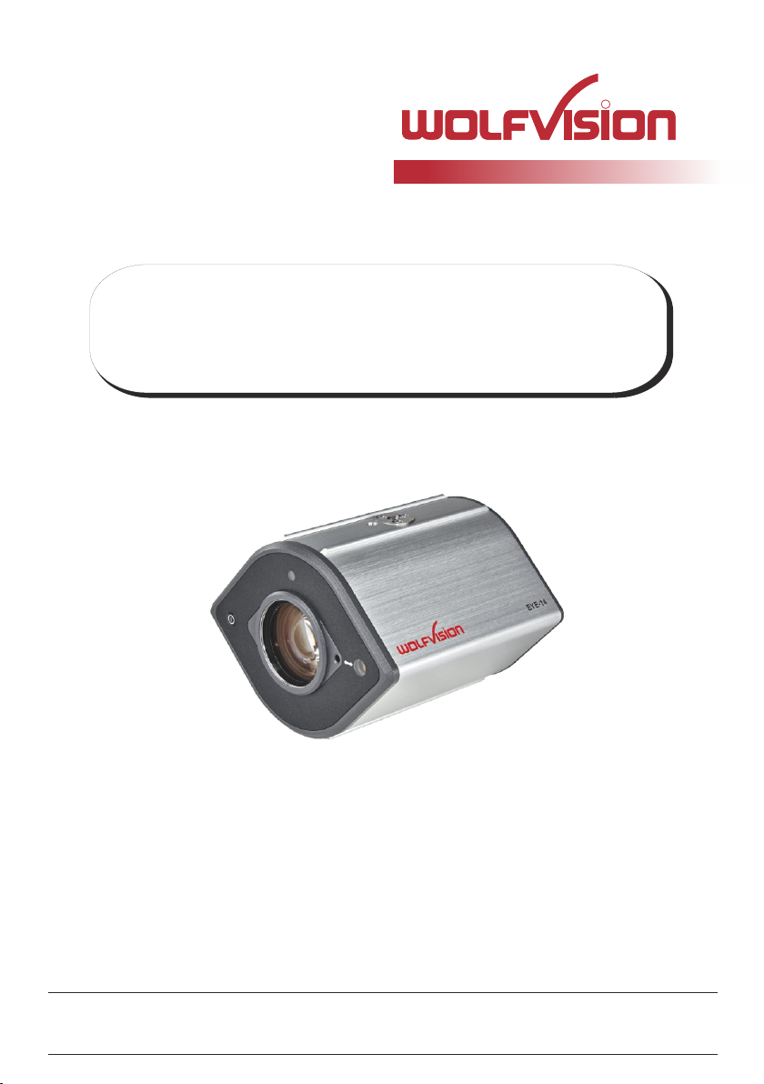
EYE-14
EYE-14
R
R
ENGLISH
Check out our Internet Homepage for additional information
www.wolfvision.com/support
Page 2
Precautions
ENGLISH
WARNING!
Risk of electric shock
Dangerous voltage inside
Please observe the following:
CAUTION! INSTALLATION AND SERVICING OF THE UNIT MUST BE PERFORMED BY QUALIFIED
SERVICE/INSTALLATION PERSONNEL FOLLOWING THE MANUFACTURER'S INSTALLATION
INSTRUCTIONS AND IN COMPLIANCE WITH THE NATIONAL ELECTRIC CODE, ALL LOCAL
BUILDING AND SAFETY CODES AND ALL OTHER APPLICABLE CODE PROVISIONS OR
REGULATIONS.
USE THIS UNIT ONLY WITH THE CORRECT VOLTAGE AS SHOWN ON THE TYPE LABEL !
DO NOT EXPOSE THE UNIT TO HEAT OR MOISTURE !
PROTECT THE UNIT FROM EXCESSIVE SHOCKS !
USE SECURITY ROPE TO PREVENT IT FROM FALLING DOWN !
Make sure that sufficient air circulation for cooling the unit is possible!
If there is any abnormality (abnormal noise, smell, smoke etc.) disconnect the unit from mains
immediately and contact your WolfVision partner!
Do not use a damaged power cord. This may cause short circuits or electrical shocks!
To prevent danger, do not modify the unit or operate without the cover panel firmly in place!
Do not expose the unit to water, metallic objects or any flammable material.
Avoid installing the unit in locations exposed to strong magnetic fields or electrical currents.
Avoid installing the unit in environments where there is radiation. This could cause monitor image
distortion or damage to the camera sensor.
Do not pull the plug from the power socket with wet hands!
If the unit is not used for a long time, disconnect it from mains!
Use supplied power supply, it is approoved in accordance to CSA 22.2-60950 or UL 1950.
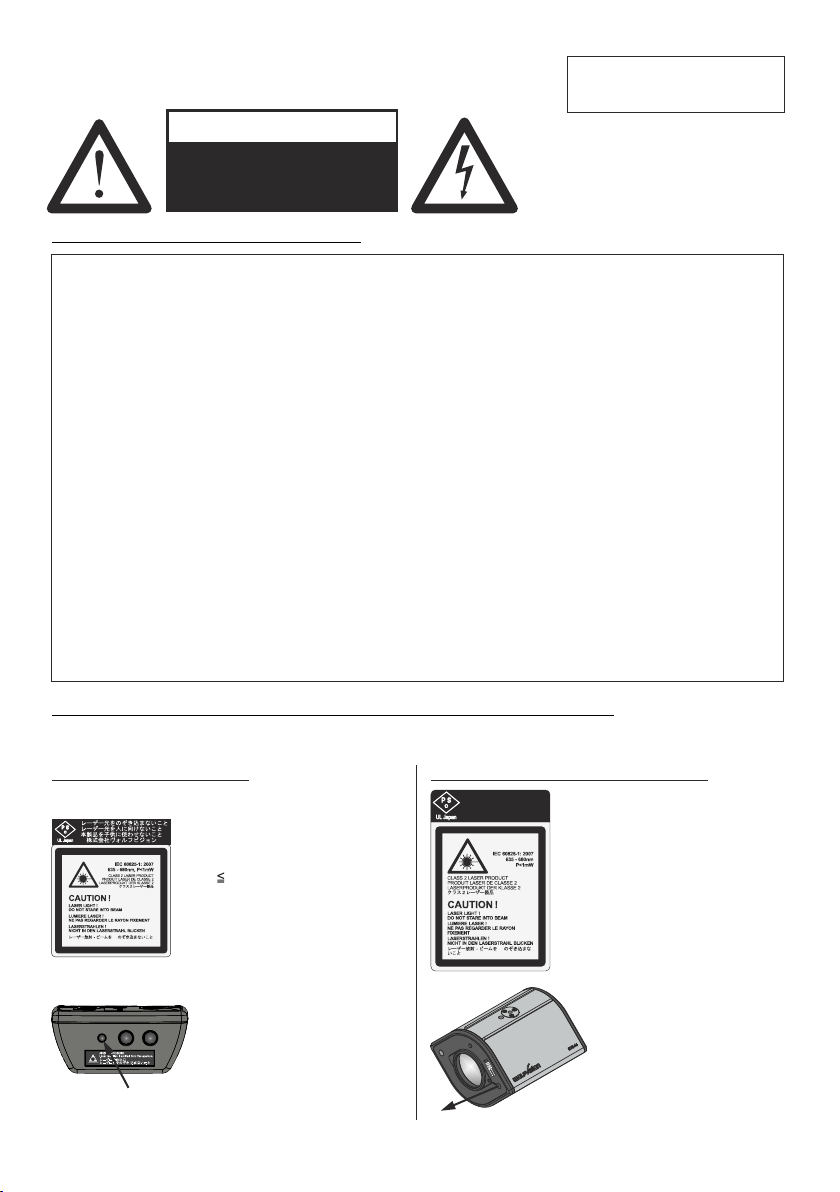
Precautions for the laser pointer and laser center marker:
Laser light - Do not stare into beam!
Do not modify the laser! Do not view the laser beam with optical instruments!
Information for laser pointer
FDA accession number: 9912688-00
This device complies with 21 CFR 1040.10 and 1040.11
Technical data:
λ = 635 - 680nm
P < 1mW
Θ 2mrad
This label will be found on the
underneath of the remote
control.
The laser beam exits the
remote control through the
smaller (left) opening on the
front.
Information for the Center Lasermarker
1
レーザー光をのぞき込まないこと
レーザー光を人に向けないこと
本製品を子供に使わせないこと
株式会社ヴォルフビジョン
Technical data:
λ = 635nm - 680nm
P < 1mW
cw/cp = 2 - 28ms
This label will be found on the
camera.
The beam of the Center
Lasermarker exits the unit
beside the camera lens.
(arrow indicates the laser
beam)
Page 3
Approval
Marks on the unit:
Warning!
This is a class A device. Operation of these equipment in a residential area is likely to cause harmful
interference in which case the user will be required to correct the interference at his own expense.
FCC information:
This device complies with part 15 of the FCC rules. Operation is subject to the following two conditions: (1)
this device may not cause harmful interference, and (2) this device must accept any interference received,
including interference that may cause undesired operation.
Note:
This equipment has been tested and found to comply with the limits for a class A digital device, pursuant to
part 15 of the FCC rules. Operation of these equipment in a residential area is likely to cause harmful
interference in which case the user will be required to correct the interference at his own expense.
Information to user:
The user manual or instruction manual for an intentional or unintentional radiator shall caution the user that
changes or modifications not expressly approved by the party responsible for compliance could void the
user's authority to operate the equipment.
This product is built according to Directive EMC and to Directive electrical equipment.
Inspections, tests and evaluation are according to UL 60950. CSA 22.22-60950
Inspections, tests and evaluation are according to the CB-Scheme
Inspections, tests and evaluation are according to the PCT-Scheme
Tested to comply
with FCC standards
Worldwide Patents
EU 0 362 737 KR 128059 AU 765617
DE P58907684.1-08 US 5,027,219 CN ZL99118847.0
CN 89107780.4 EU 0 987 874 and others
JP 1725033 JP 3 544 900
Copyright Information
Copyright © by WolfVision. All rights reserved.
WolfVision, Wofu Vision and are registered trademarks of WolfVision Holding AG, Austria.
No part of this document may be copied, reproduced, or transmitted by any means, without prior written
permission from WolfVision. Except documentation kept by the purchaser for backup purposes.
In the interest of continuing product improvement, WolfVision reserves the right to change product
specifications without notice.
Information in this document may change without notice.
Disclaimer: WolfVision shall not be liable for technical or editorial errors or omissions.
The units are "MADE IN EU/AUSTRIA”
Printed in Austria, May 2014
2
Page 4
Components of the EYE-14
#6
#7
#5
#4
#3
#6
#2
#1
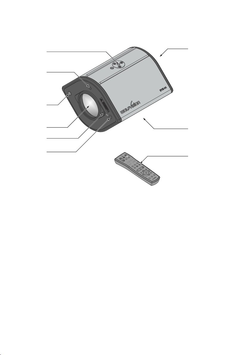
#1 Center Lasermarker (see pages 7 and 8)
Important: Do not stare directly into the laser beam. This is hazardous for your eyes!
#2 Adjustment screw for Center Lasermarker (see page 7)
#3 Camera lens
additional lenses or filters can be attached (M42x0.75mm)
#4 Power Button (see page 7 and page16)
#5 IR-receiver (see page 21)
#6 Tripod Mount 1/4" UNC-20 to attach the EYE-14 to tripod or wall/ceiling mount (top and bottom)
(see pages 20, 21 and 22)
#7 Connectors (shown on next page)
#8 IR-remote control (see pages 5, 6 and 24)
#8
#8
3
Page 5
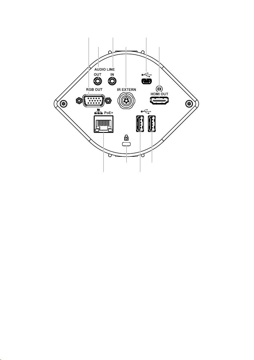
Connectors (#7)
#10
#15
#11
#13
#12
#16
#17
#9
#9 RGB OUTput (15pin) (see page 16)
#10 AUDIO Line Out (see page 7)
#11 AUDIO Line In (see page 7)
IR-EXTERN input for additional IR-sensor (see page 21)
#12
#13 USB port to Computer (to host) (see pages 18 and 19)
#14 HDMI OUTput (see page 16)
#15 LAN port (see pages 14, 18 and 19)
Kensington Lock® (see page 20)
#16
USB port to USB storage device (to client) (see pages 18)
#17
USB port to WLAN dongle (to client) (optional, see page 21)
#18
for audio signals
for audio signals
10/100 BASE T/TX
#14
#18
USB ports #17 and #18 are interchangeable.
4
Page 6
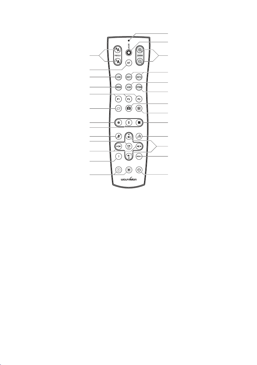
Infrared Remote Control (#8)
#32
#33
#31
#30
#29
#28
#27
#26
#25
#24
#23
#22
#21
#20
#19
#34
#35
#36
#37
#38
#39
#40
#41
#42
#43
#44
Different IR Codes
If you want to work with more than one WolfVision unit in the same room, the units should be set to different
infrared codes, in order to control them all individually.
The IR code of the EYE-14 has to match the code of the remote control.
To change the IRcode, enter the "Advanced Settings / Miscellaneous Settings" and
set the "IR Code" to A, B, C or D (code A is default). To change the IR code on the remote control,
simultaneously press PRESET 1, PRESET 2 and ZOOM TELE
combination is used, the code switches from A to B, C, D ... A ...in the given order.
For resetting the remote control to code A, simultaneously p .
The LED shows the selected code (it flashes one time for code A, two times for code B, three times for code
C and four times for code D).
on-screen menu, go to
(#27) (#34). Each time this key
ress PRESET 1, PRESET 2 and ZOOM WIDE
5
Page 7

Keys on the IR-Remote Control
#19 Manual EXPOSURE keys (brightness adjustment)
When the EXPOSURE keys are pressed, the unit changes the image brightness (see page 9).
#20 ? HELP / RESET key for on-screen menu (double function)
Shows the info screen to inform you about current state of recording and audio (see page 9).
While you are in the on-screen menu you can activate the on-screen help by pressing the HELP key.
Pressing this key for 2 seconds resets the selected menu item (see page 15).
#21 Backward-Forward keys / MENU NAVIGATION keys (double function)
For navigating through the memory in MEM and USB mode (see page 12).
For navigating through the on-screen menu while it is activated (see page 15).
#22 OK key
Acts as Enter key while the on-screen menu (see page 15), MEM or USB mode is activated (see page 12).
Pauses and resumes playing video files when kept pressed for 4 seconds.
#23 Audio Mute key
Mutes the Audio inputs.
#24 Video Recording Pause key
Pauses video recording, click again to resume (see page 11).
#25 Video Recording key
Start video recording (see page 11).
#26 PiP key
For activating the Picture in Picture mode for Live to Freeze comparison (see page 13).
#27 PRESET keys (programmable settings)
For storing a preset, press one of the PRESET keys for more than 2 seconds. For recalling a preset, press
the PRESET key quickly (see page 9).
#28 MEM key
For displaying pictures and videos from the internal memory (see page 12).
#29 LIVE key
For displaying the live image of the camera (see page 12).
#30 AUTO FOCUS (AF) key
Pressing this key toggles the Auto Focus on and off (see page 9).
#31 Manual FOCUS keys
For focusing the picture (see page 19).
#32 LASER POINTER indication LED
Indicates active Laser LED.
#33 LASER POINTER key
Important: Do not stare directly into the laser beam. This is hazardous for your eyes!
#34 ZOOM keys
Controls the camera zoom to change size of pick-up area.
#35 EXT1 and EXT2 keys - no used.
#36 USB key
For displaying pictures and videos from the USB memory (see page 12).
#37 STRM key
Shows the signal of the received stream - requires Feature Pack BYOD (see page 21).
#38 SNAPSHOT key
Pressing this key activates the SNAPSHOT function (see page 11).
#39 FREEZE key
Freezes the current image (see page 9).
#40 Video Recording Stop key
Stops video recording (see page 11).
#41 Stream key
Starts and stops streaming over the network (see page 14).
#42 Audio Volume keys / MENU NAVIGATION keys (double function)
To increase / decrease volume of audio output (see page 17).
For navigating through the on-screen menu while it is activated (see page 15).
#43 MENU key
Pressing MENU key activates the on-screen menu (see page 15).
#44 POWER key
Pressing this key switches the unit on and off. When powering on, the unit runs the power-on preset.
6
Page 8
Basic Preparations
1. Connect the PoE+ power supply to the unit (#15) and plug it to mains
2. Connect a viewing monitor or a projector to the outputs of the EYE-14
For choosing the right output mode please see page 16!
3. The power indication LED on the unit is illuminated. (white for Standby and green for fully powered-up).
4. By default, the EYE-14 will be fully powered-up when mains is supplied.
When the default behaviour is changed by the user, press the POWER key
(#4 or #44 on the remote control).
5. The EYE-14 now runs the “power-on preset”.
Power-on preset:
Automatically zooms to a middle zoom position, focuses on the working surface and activates the auto iris
(the size of the pick-up area depends on the mounting height of the EYE-14).
As soon as the Power Indication LED is green and stays illuminated, you can start working with the unit. The
behavior of the unit once the power has been supplied or after the POWER key has been pressed can be
changed in the unit's on-screen menu (see page 15).
Operating the EYE-14 for the first time - Quick Setup Guide
When the unit is switched on for the first time, the Quick Setup Guide will open automatically on-screen
(visible on HDMI and RGB outputs). Use the arrow keys on the remote control to navigate through the menu
The settings are:
Language
Select the desired language for the on-screen menu.
Ethernet Settings
The IP-address, Subnet Mask and Gateway IP-address can be set automatically by a DHCP-server or
manually.
Time Settings
The EYE-14 offers the possibility to use the internal clock or an external time server (a time valid time server
IP address and internet connection are required).
Audio Settings
Set up audio configuration. Line-In is switched off by default and can be activated when needed.
.
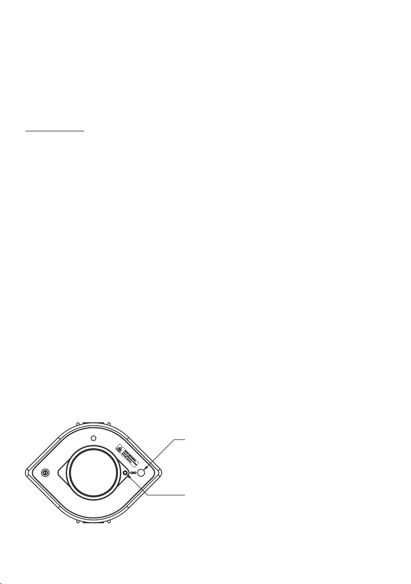
When the EYE-14 is mounted on it‘s correct place, the laser center marker has to be adjusted.
Enter the on-screen menu Advanced Settings / Miscellaneous Settings and change the item ”Laser
Marker” to ”ADJUST” to enable visibility of the cross hair and laser marker in the picture.
Move the laser dot by turning the adjustment screw until it matched the cross hair (Allen key size 2.5mm).
When done, set ”Laser Marker” to ”ON” for normal operation.
Please note: The Center Lasermarker adjustment is a onetime setup, which must only be performed again
if the distance between EYE-14 and table is changed!
For more information check the video file on the internal memory of the device (built-in memory).
Exit of laser beam
Important: Do not stare directly into the laser beam!
Adjustment screw to adjust the Center Lasermarker.
Allen key size 2.5mm (alternative 3/32" key can be used)
Do not turn the screw with excessive force to prevent
damaging the thread!
This is hazardous for your eyes!
7
Page 9
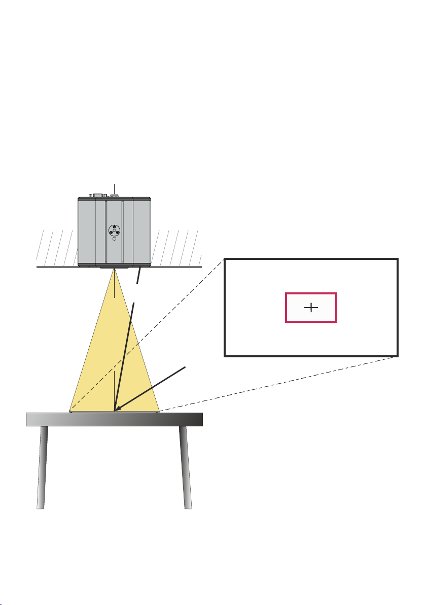
Shooting Area On The Working Surface
1. The Center Lasermarker on the working surface marks the center of the pick-up area of the built-in
camera. Just center your subject material to the laser spot.
2. Select the enlargement required with the ZOOM keys (#34).
3. The Auto Focus will adjust the sharpness automatically. The focus can be adjusted manually by using
the FOCUS keys (#35).
The Center Lasermarker marks the center of the pick-up area of the built-in camera on the working surface.
The laser beam is made for flat objects and it is not visible in the image.
Due to the oblique mounting of the camera and the laser module, the laser beam shifts to the left or right
edge of the pick-up area when the distance between the EYE-14 and the scanned object is changed (e.g.
when capturing tall objects).
This means that the laser beam no longer exactly marks the center of the pick-up area.
EYE-14
screen
Ceiling
laser beam of
center marker
Picture center
center of pick-up are
8
Page 10

Focusing / Autofocus
When the unit is turned on the focus automatically adjusts to the object.
Please note that objects with very low contrast (like a blank sheets of paper) are difficult to focus.
For special applications the autofocus can also be switched off using the on/off switch (#30). The autofocus
is also switched off when the manual FOCUS keys (#31) are used.
Optical Zoom / Digital Zoom
Please note that the EYE-14 has an optical 14x zoom. The digital 4x zoom increases the overall zoom
range to a 56x zoom. The pick-up sizes are dependent on distance between camera and object.
When you zoom in, the zoom will be stopped at optical end position, when you zoom in further the digital
zoom is automatically activated to extend the optical tele.
However please be aware that when the digital zoom is used, the resolution of the picture is not as good as
before.
The behavior of the EYE-14 in the digital zoom mode can be changed in the on-screen menu (see page 15).
Automatic / Manual Exposure
EYE-14 is equipped with an auto exposure to control gain, shutter and mechanical iris. This means that the
brightness of the camera image adjusts automatically.
Using the EXPOSURE keys (#19) manually darkens or brightens the image.
The standard auto exposure level (Image Brightness) can also be set brighter or darker in the unit's onscreen menu.
When picking up areas with bright spots, Back Light Compensation can be switched on in the unit‘s onscreen menu.
When changing Shutter to OFF or 1/30, the Center Lasermarker will be switched off to prevent visibility in
the picture. For temporarily switching the laser on in such situation, assign the LASER function to a preset
key - see below.
Preset Function
The unit offers the possibility to store the current settings as a Preset and recall them by just pressing the
respective PRESET key (#27) on the remote control.
For storing a reset adjust y function as required and then PRESET key
remote control or more will
As mentioned above, when presets are stored all current settings such as zoom, focus, iris etc. are also
p : an press any one of the s on the
for 2 seconds . An on-screen message inform you when the Preset is stored.
stored. Contrary to this, a user also has the opportunity to assign specific functions such as "NEGATIVE",
"NEGATIVE/BLUE", "BLACK/WHITE", "FREEZE", "LASER" etc. to a PRESET key in the on-screen menu
of the EYE-14 (see page 15).
Freeze
The current image can be captured by pressing the FREEZE key (#39).
This can be used to prepare the next object while the audience is watching the frozen image.
Info Screen (status)
The info screen will be displayed by pressing the ? HELP key (#20) on the remote control.
Information like currently available recording time, recording state and audio settings will be displayed.
The info screen will be hidden after a few seconds automatically.
Status Icons
At the left lower corner, respective icons will inform you about active streaming, recording and mic status.
9
Page 11

White Balance Adjustment
IMPORTANT
Correct white balance adjustment is important for for accurate color reproduction
Each time the lighting condition changes, the camera must readjust its white balance, in order to optimize
the color reproduction. The lighting condition (color temperature) changes, for example, if changing
between room light and an external lightbox (optional bottom light) or when changing to sunlight.
The standard setting of the EYE-14 is "Auto Tracking" white balance.
continuously adjusted automatically.
This means that the white balance is
For an exact white balance, at least 10% of the recorded image should be white.
For a precise fixed white balance adjustment use the "One Push" white balance. This can be done by
pressing the assigned PRESET key . When the white balance is stored an on-screen
(WHITE BALANCE)
message appears. Setting a "One Push" white balance switches off the "Auto Tracking" mode (when the
unit is switched off and on again the "Auto Tracking" mode will be reactivated).
Normally there is no need for a manual white balance adjustment. However, if the colors on the screen still
appear to be wrong, the white balance can be adjusted manually (one-push):
Hints to perform a One-Push white balance:
Top light (and room light):
Zoom in on a white object (e.g. a sheet of paper) until there is only white on the screen and press the
assigned PRESET key (WHITE BALANCE).
Optional Lightbox with transparencies:
Turn off the room light and switch on the lightbox. Remove everything from the light box, zoom to the
smallest picture size until there is only white on the screen and press the assigned PRESET key (WHITE
BALANCE).
Optional Lightbox with x-rays:
Turn off the room light and switch on the lightbox. Place an x-ray on the light box, zoom out until the whole
x-ray is picked up and press the assigned PRESET key (WHITE BALANCE).
Please note: False colors can also be caused by incorrect color settings on a connected projector or
monitor. It is recommended to adjust the white balance of the EYE-14 at first and if the results are still not
satisfactory, the monitor or projector should be checked.
For specialists: The EYE-14 can be switched between "Auto Tracking", "One Push" and "Manual" white
balance mode in the on-screen menu (see page 15). If you work with negative transparencies and a
lightbox, use a blank (black in the image) part of the negative film for white balance adjustment!
10
Page 12

Snapshot - Storing Single Shots
By pressing the SNAPSHOT key (#38) the current image is stored in the next free memory
Built-in Memory (external storage device not connected)
The EYE-14 uses internal memory with 8GB storage for snapshots and video recordings.
Pictures (and videos) can be viewed in the MEM mode of the EYE-14.
All pictures are stored in JPG format with date and time stamp (WV_JJJJMMDD_hhmmss).
Example: WV_20130919_024735.jpg
An on-screen message will tell you the file name.
External storage device connected
The EYE-14 uses the external storage device for snapshots and video recordings. The available space
depends on the device used.
All pictures are stored in JPG format consecutively numbered with date and time stamp
(WVxxxxxx_JJJJMMDD_hhmmss). Example: WV_20130919_024735.jpg
An on-screen message will tell you the file name.
Pictures (and videos) can be viewed in the USB mode of the EYE-14, or on a computer when respective
picture viewing software is installed.
The properties of the USB functions can be changed in the on-screen menu (Advanced Settings - USB Stick
Settings), like default folder (document directory) and the file names ("WV" and consecutively numbered).
.
Video - Recording Video Clips
The EYE-14 supports video recording in a multimedia-container format with codec H.264 inclusive audio
(video file extension is *.avi).
Just select the desired video source (camera live image or memory) and audio setting in the on-screen
menu and start recording with the REC key (#25). The recording can be paused and resumed with the
PAUSE key (#24) and stopped with the STOP key (#40).
Use the Audio VOLUME keys (#42) to adjust the volume or the MUTE key (#23) to mute audio.
Hints:
A symbol in the left lower corner indicates active recording function.
The unit activates codec H.264 automatically when recording is started (Advanced Settings /
Streaming/Record Settings).
The video files are saved into internal memory or onto an external USB storage device when connected.
Files will be named with date and time stamp (WV_JJJJMMDD_hhmmss).
Example: WV_20130919_024735.avi
An on-screen message will tell you the name of the recorded file after recording is stopped.
Hint: By pressing the ? key (#20) the current state of recording will be displayed on-screen, like available
recording space and audio settings.
Built-in Memory (external storage device not connected)
The EYE-14 uses the internal memory with 8GB storage for snapshots and video recordings.
Videos (and pictures) can be viewed in the MEM mode of the EYE-14.
External storage device connected
The EYE-14 uses the external storage device for snapshots and video recordings. The available space
depends on the device used.
Videos (and pictures) can be viewed in the USB mode of the EYE-14, or on a computer when respective
video viewing software is installed.
The default folder (document directory) can be changed in the on-screen menu (Advanced Settings / USB
Stick Settings).
Please note, a video file is recorded each time you press the REC key. If file size exceeds 4GB, a new file will
be created automatically.
11
Page 13
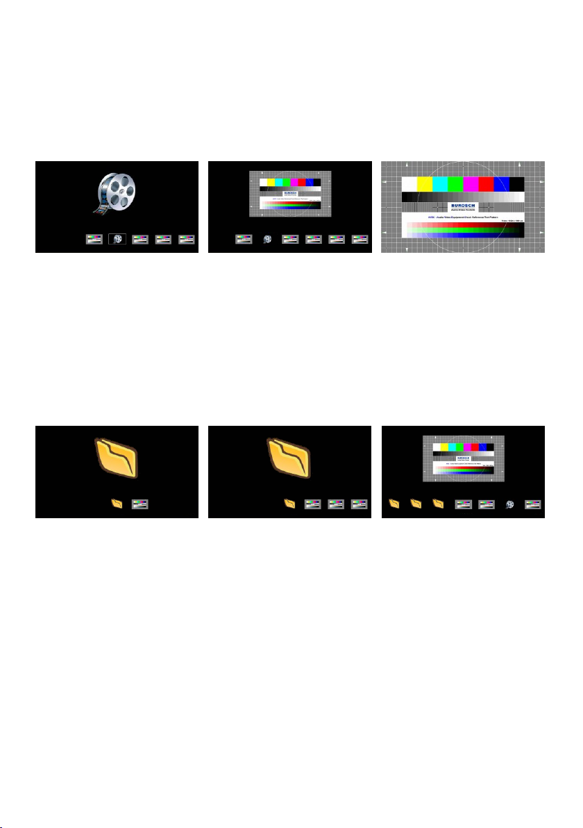
MEM Mode
To start the MEM mode, press the MEM key (#28). A split image with the stored pictures will be displayed.
Additionally a status line with picture information is shown on the bottom of the screen.
Pressing the LIVE key (#29) returns to the camera live image temporarily. The presentation will stay at the
last picture shown. To continue, use the MEM key.
To select one of the currently displayed pictures move the picture bar with the Backward/Forward keys (#21)
and confirm it with the OK key (#22). Use Backward/Forward keys to show the previous/next picture. Use
the OK key to return to the split view.
WV_20130919_030215.vid (1/9)
split image
WV_20130919_224920.jpg (1/9)
split image full image
Use the MENU key for deleting pictures and/or videos.
Stored pictures and video clips can be copied to USB stick in the on-screen menu of MEM mode.
USB Mode
To start the USB mode, press the USB key (#36). A split image with the available folders and stored pictures
will be displayed. Additionally a status line with picture information is shown on the bottom of the screen.
Pressing the LIVE key (#29) returns to the camera live image temporarily. The presentation will stay at the
last picture shown. To continue, use the USB key.
To select one of the currently displayed pictures move the picture bar with the Backward/Forward keys (#21)
and confirm it with the OK key (#22). Use Backward/Forward keys to show the previous/next picture. Use
the OK key to return to the split view.
WOLFVISION (1/9)(1/2)
selected folder ”My_Documents”
(1/9)/WOLFVISION (1/4)My_Documents
selected image ”pattern.jpg”initial screen
Use the MENU key deleting single pictures or videos.
For further organization of the USB storage device use your computer; like creating or deleting folders,
moving pictures from one folder to another, deleting pictures and/or videos or formatting of the USB storage
device.
Please note formatting the USB storage device will delete all data.
Supported file systems are FAT16 and FAT32.
Supported picture file format is JPG format.
Supported video file format is a multimedia-container with codec H.264 (video file extension is *.avi).
pattern.jpg (1/9)/My_Documents/My_Documents
12
Page 14
Built-in Digital Scaler (USB-Stick and vSolution Connect)
The EYE-14 has a built-in digital image scaler which can scale the received stream of vSolution Connect
(iPad) and images from a connected USB-stick automatically to the current output mode of the unit (For
example: If the EYE-14 is set to output an 1080p (FullHD) to the projector but the image from the USB-stick
has just 720p resolution, the scaler of the EYE-14 converts the 720p image to 1080p. As a result the
projector does not readjust the input mode when switching between the live camera and other content).
The output resolution of the EYE-14 can be changed in the on-screen menu (see page 15).
vSolution Connect requires the BYOD Feature Pack.
Integrated Seamless Switch
The EYE-14 has an integrated Seamless Switch.
This allows for a seamless transition (fade-over/dissolve effect) when switching between the camera
image, the memory (internal and USB-stick), or stream of vSolution Connect.
The behavior of the EYE-14 can be changed in the on-screen menu (see page 15).
vSolution Connect requires the BYOD Feature Pack.
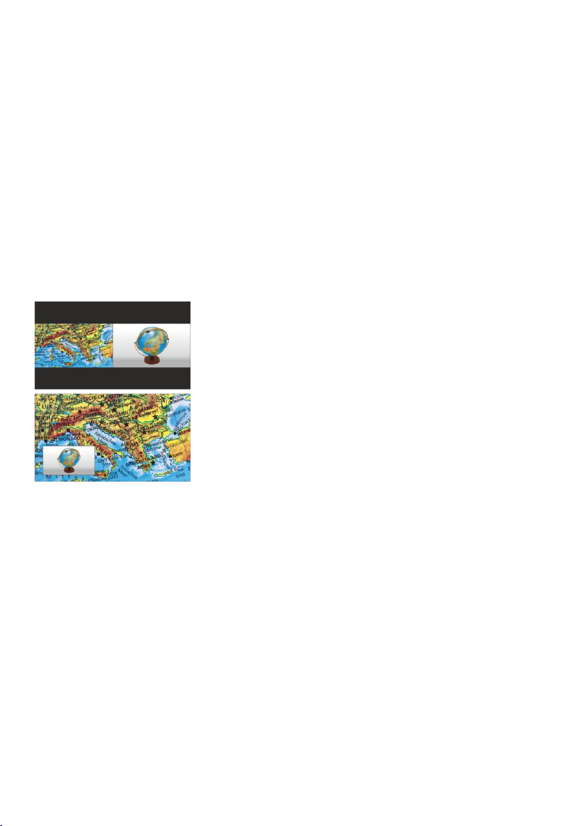
Live to Freeze Comparison / Picture in Picture (PiP)
The Picture in Picture Mode offers the possibility to show two different
pictures at the same time on one screen. Just press
to activate the Picture in Picture mode. The current picture (e.g. image
memory) will be shown side-by-side to the live image or in the lower left
corner and the live image will be shown in the upper right corner. The
size of the live image is much bigger.
The content of the live image can be changed e.g. by recalling a stored
image memory.
Following comparisons are possible: image memory, live image. The
content from the small image is frozen.
The behavior of the PiP mode can be changed in the on-screen menu,
Output Settings (see page 15).
the PiP key
(#30)
13
Page 15

Send Stream to Network
The EYE-14 has a built-in streaming server which is capable of broadcasting audio and video content over
the network.
Prepare Ethernet connection (wired or wireless) and select ”Streaming Settings” in the on-screen menu
Advanced Settings / Ethernet Settings. There you can assign the IP address of the destination (for multicast
select: 225.0.0.0 to 238.255.255.255; with all other addresses the stream can be received at one
destination only; 224.x.x.x and 239.x.x.x are reserved.), port, mode, resolution, frame rate and format of the
stream (up to RTP H264).
With mode setting ”AUTO” the EYE-14 streams on demand only. The WolfVision vSolution Link Software
and most internet browsers can start the stream automatically. In case your browser or third party
application (media player) cannot start the streaming function, use the STREAMING key or change
the mode to ”Continuous” for permanent streaming (please note the resulting network traffic).
Select desired resolution, frame rate and format (keep in mind, these settings are influencing the network
traffic).
To open the stream with a third party application, just input the network URL into the address field:
Internet Browser, example: http://192.168.0.2
Media Player, example: http://192.168.0.2/stream.sdp
The IP address is the IP-address of the EYE-14 (on-screen menu Advanced Settings / Ethernet Settings).
The EYE-14 broadcasts the currently shown content of video (live camera, or memory) and audio (Line-In)
to the network.
Technical Background: UDP Multicast works like a broadcast - many clients are watching the same video
stream. In Multicast mode the bandwidth is always the same, no matter how many computers are
connected. However as many routers do not support Multicast, UDP Unicast can be used instead for pointto-point connection (one client is possible).
In TCP Singlecast mode each computer opens a separate connection to the EYE-14, which requires a lot of
bandwidth if many clients are connected (max. 128 connections). Audio is not supported.
Hints:
For full functionality JAVA version 7 or higher is necessary when using a browser to listen.
For full functionality following ports are necessary: 50915, 50913, 50921, 8800 and 8801 (by default).
Ensure that the used port and IP-address is not blocked by any firewall.
Please note, some network routers are not able to forward multicast streams.
(#41)
14
Page 16

The following chapter is for experienced users only:
ON-SCREEN MENU / ON-SCREEN HELP
For regular use of the WolfVision EYE-14, it is not necessary to go into the unit's menu and change settings.
Inexperienced users should not make any adjustments here.
To enter the on-screen menu press the MENU key (#43). Settings of the unit's basic functions and the built-
in camera can be made here using the 4 SELECT keys on the remote control (#22 and #43) and the OK key
(#23).
If more information on a function in the on-screen menu is required, set the cursor in the respective line and
press the ? HELP key (#20) to display a detailed description of this function on the screen. To exit the help
function, press the ? key again.
By pressing the MENU key for 4 seconds the Extra Menu appears. In the Extra Menu, e.g. the Factory
Reset can be performed to reset all settings including resolution and IP addresses to the default.
The functions of the on-screen menu are not described in detail in this user manual as the help menu is an
integrated part of the unit's software (firmware). The information you see on your screen always belongs to
the current EYE-14 firmware.
Exposure Settings
The exposure settings will affect the brightness of the image, e.g. Gain, Shutter, Aperture, Image
Brightness and Back Light Compensation.
Color Settings
The Color Settings will affect the color reproduction of the camera, e.g. White Balance settings, Color Mode
and Positive/Negative.
Hint:
If the picture on your screen appears to be too light or too dark or the color saturation is not correct, the Color
Mode can be changed.
For better readability of handwritten texts, the image can be changed to BLUE.
Output Settings
To change the Detail Settings (sharpness) and to change the Output Resolution manually.
Hint:
Use the "Resolution Test" function to change to the selected resolution temporarily for ten seconds. This
way the compatibility of the connected display device can be easily checked.
Preset Control
In the "Preset Control" the Preset keys can be assigned specific functions such as "NEGATIVE/BLUE",
BLACK/WHITE", "LIGHT", etc.. Additionally the default presets can be recalled.
Advanced Settings
In this sub-menu the behavior when powering on, digital zoom, on-screen menu can be changed.
Settings for Ethernet (LAN), Date/Time, Laser and USB stick will also be found in this menu.
Hint:
Change Power-Down Mode to "ECO" or "DEEP" to save power consumption in standby mode.
Open "Device Info" to view details of the unit like currently installed firmware version.
Recall Default Menu Settings
All picture affecting settings can be set back to the factory defaults. All settings which affect the
communication with other equipment, e.g. network settings and resolution will not be changed.
Hint:
To reset single items, just select the desired line and keep ? HELP key (#20) pressed for 2 seconds.
Start Quick Setup Guide
The Quick Setup Guide will be started automatically when the EYE-14 is switched on the the first time and
can be started with this item manually. This menu will guide you through basic settings like language,
network settings, time/date and audio settings.
15
Page 17
HDMI/RGB Output #14 and #9 Choosing the Correct Output Mode
The HDMI and RGB outputs (#22 and #21) can output signals in following formats:
- SVGA (4:3 - 800x600 pixels) at 60Hz
- XGA (4:3 - 1024x768 pixels) at 60Hz
- SXGA ( - 1280x1024 pixels) at 60Hz
- UXGA (4:3 - 1600x1200 pixels) at 60Hz
- 720p (16:9 Widescreen HD - 1280x720 pixels) at 60Hz
- 1080p (16:9 Widescreen HD - 1920x1080 pixels) at 30 and 60Hz
- WXGA* (16:10 Widescreen - 1280x800 pixels) at 60Hz
- WUXGA (16:10 Widescreen - 1920x1200 pixels) at 60Hz
5:4
The "Auto resolution" function is activated by default. In this mode the EYE-14 continuously checks which
devices are connected to the RGB (#9) and automatically sets the optimal output
mode for the connected device.
HDMI output (#14) and
Please note that the EYE-14 cannot check the possible resolution if the
connected units or the cables** are not "Plug and Play" compatible. If the EYE-14 cannot detect the
resolution of the connected device, the output is set to the default ofXGA/60Hz.
(**Cables with plug and play compatibility must support DDC).
If you cannot use the "Auto resolution" function, you can select the output mode manually in the on-screen
menu of the unit (see page 18).
In order to achieve the best picture quality you must set the outputs of the EYE-14 to match the native
resolution of your display unit (e.g. LCD or DLP projector or monitor).
Important: What matters is the native resolution of the projector or monitor, not the maximum resolution that
it can display (in compressed mode). The native resolution is the actual number of pixels of the built-in LCD
display or DLP chip of a projector or monitor. Most LCD or DLP projectors can also display higher
resolutions than their native resolution, but only in compressed mode and with inferior picture quality.
Do NOT set the output of the EYE-14 to a higher standard than the native resolution of your display
unit. Follow the instructions in the user manual of the connected units.
Please note, when the aspect ratio does not match the native resolution of the EYE-14 or display device,
black bars on top/bottom or left/right can be shown. Some display devices offer the possibility to zoom-in the
image to minimize the black bars. Follow the instructions in the user manual of the connected units.
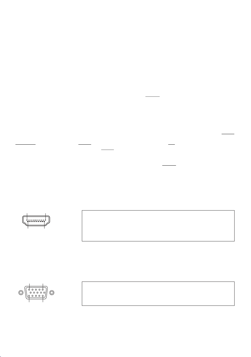
HDMI Port (#14)
19 1
18 2
19-pin HDMI
connector female
(front side, unit)
CEC ( ARC (Audio Return Channel) and HEC (HDMI Ethernet Channel) are
Consumer Electronic Control),
not supported. DC+5V are available when unit is fully powered up.
1 - T.M.D.S. Data2+
2 - T.M.D.S. Data2
3 - T.M.D.S. Data2- 10 - T.M.D.S. Clock+ 17 - DDC Ground
4 - T.M.D.S. Data1+ 11 - T.M.D.S. Clock Shield 18 - DC+5V (max. 50mA)
5 - T.M.D.S. Data1 Shield 12 - T.M.D.S. Clock 19 - Hot Plug detect
6 - T.M.D.S. Data1- 13 - Reserved
7 - T.M.D.S. Data0+ 14 - ARC (Audio Return)
8 - T.M.D.S. Data0 Shield 15 - SCL (I²C Serial Data Line for DDC)
Shield 9 - T.M.D.S. Data0- 16 - SDA (I²C Data Line for DDC)
RGB Port (#9)
1
5
15
15-pin D-Sub HD
connector female
(front side, unit)
11
1 - Analog Red video 6 - Red return 11 - N/C Not connected
2 - Analog Green video 7 - Green return 12 - SDA I²C data
3 - Analog Blue video 8 - Blue return 13 - HSync Horizontal sync
4 - N/C Not connected 9 - DC+5V max. 50mA) 14 - VSync Vertical sync
5 - GND Ground 10 - GND (VSync, DDC) 15- SCL I²C clock
DC+5V are available when unit is fully powered up.
16
Page 18
Audio Line In and Line Out #10 and #11
L
R
GND
The EYE-14 can handle different audio sources and different audio outputs. Enter the onscreen menu Advanced Settings / Audio Settings and select the desired settings.
Line In: max. 1VRMS @ 10kOhm (stereo, unbalanced)
Line Out: max. 1VRMS @ 10kOhm (stereo, unbalanced; max. transmission rate 1:1)
Volume of audio output can be decreased in steps of 10% (affects HDMI audio too).
Hint:
Some microphone systems are requiring a pre-amplifier.
In case you encounter hum noise caused due to ground loops, check installation. When it
cannot be solved, add ground-loop isolators to both audio lines (LineIn and LineOut).
Transmission range: 20Hz~20kHz at / 3dB / 300Hz~10kHz at / 1dB
Transmission ratio: 1:1
+ +
- -
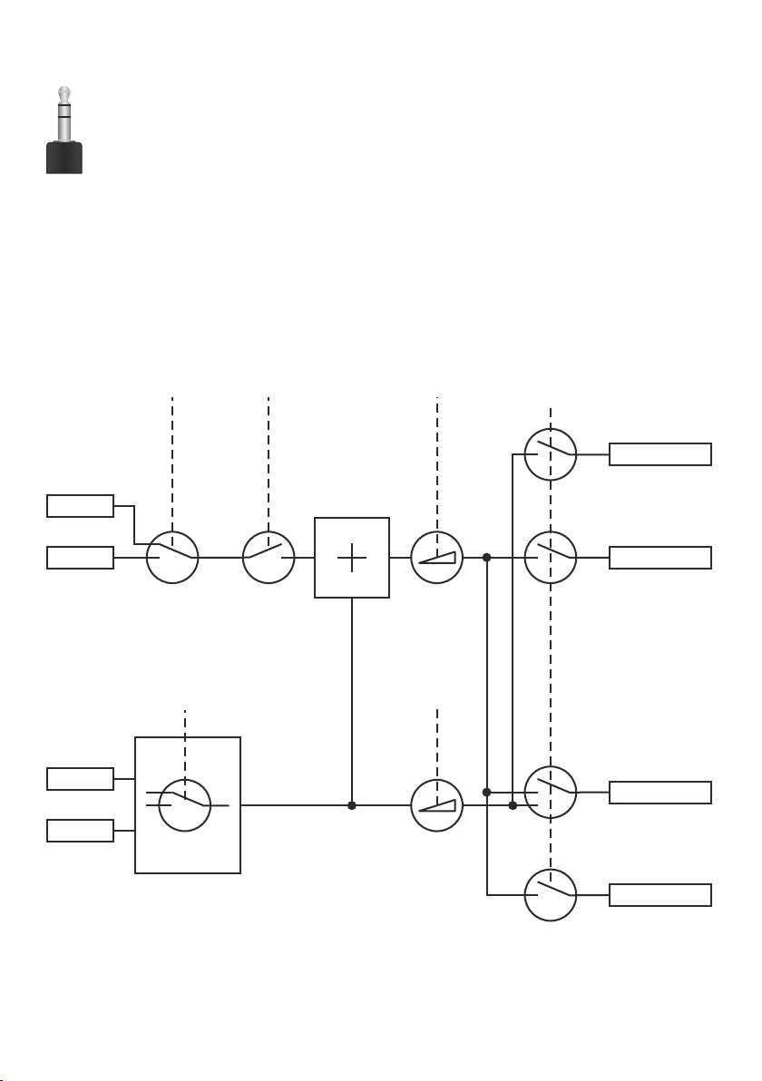
Audio Concept
The Audio Concept indicates the behaviour of the audio processing depending on different menu settings.
Off
Line In
Playback
Stream
OSD Setting
Microphone
IR Control
Switched
with source
IR Control
Mic Mute
IR Control
Volume
IR Control
Volume
OSD Setting
All / Mic / No
All / No
HDMI
OFF
NO MICRO
Stream
OFF
ALL SOURCES
Line-Out
OFF
ALL SOURCES
NO MICRO
Recording
OFF
ALL SOURCES
17
Page 19

USB Port to Storage Device (host) (#17)
The USB client port can be used for expanding memory to save pictures and video files (see pages 11and 12).
Additionally it can be used to store menu settings and updating the firmware.
Note max. power consumption of 500mA.
Saving Settingsof the EYE-14 onto a USB Stick
The EYE-14 offers the opportunity to save menu settings inclusive presets onto an USB stick as XML file.
Change the settings to the desired values and store it on the USB stick (in the on-screen menu, Advanced
Settings / USB Stick Settings).
When connecting an USB stick with the prepared XML file, an on-screen message will pop-up.
The behaviour of the unit can be changed in the on-screen menu (see page 15).
As soon as the USB stick is removed, the previous settings are restored.
USB Port to the Computer (client) (#13)
The USB device port can be used for direct connections between the EYE-14 and a computer.
PTP functionality (Picture Transfer Protocol, version 1.0)
The PTP functionality offers the ability to access the built-in memory by using a file browser. No additional
device driver will be needed (depending on used operating system on the PC).
UVC Driver (Universal Video Class, version 1.0)
The EYE-14 is UVC compatible and can be used as webcam. No additional device driver will be needed
(depending on used operating system on the PC).
Video Capture Driver (stand alone and part of vSolution Link)
The video capture driver is WIA (Windows Image Acquisition) compatible and can be used together with
graphics software, like Adobe Photoshop , or in combination with Interactive Whiteboards.
Please download the latest version of Video Capture Driver from: www.wolfvision.com (Support)
vSolution Link by WolfVision
Use the software vSolution Link to control the EYE-14 and to use it as a scanner for 3-dimensional objects.
Images in JPG, TIF or BMP format can be taken in a fraction of a second. Additionally video files can be
stored and the EYE-14 can be administrated.
Stored pictures are including EXIF data (available with format JPG or TIFF only). Included data are:
Manufacturer = WolfVision
WolfVision model (inclusive serial number) = e.g. EYE-14 (01041472)
Firmware version = e.g. V1.34b
Date and time of create = e.g. 2014-05-01 11:06:29 (yyyy-mm-dd hh:mm:ss)
Please download the latest version of vSolution Link from: www.wolfvision.com (Support)
®
Ethernet / LAN Port (#15) 10BASE-T/100Base-TX
The LAN port makes the EYE-14 a part of the internal computer network and it can be used for
communication over the Internet, if it is assigned an official (WAN) IP address.
Administrators of a larger number of WolfVision units can use the LAN port to support all of their units from
their local desktop PC.
The list of applications for the LAN port of the EYE-14 is constantly increasing. It can be used for controlling,
capturing still images, viewing live video streams, firmware updates, adjustments, menu settings and
maintenance purposes (some functions are supported by vSolution Link only).
The following protocols are supported: TCP/IP, IGMP, UDP and ARP.
Supporte rowsers Windows Internet Explorer, .
By default, DHCP is activated to receive all network settings automatically provided from the server.
Possible resolution up to FullHD (1080p) with WolfVision‘s vSolution Link and HD (720p) when using a
browser.
In order to prevent unauthorized users from login to the EYE-14 over the network, it is possible to set
administrator and user passwords. The transmission of the passwords over LAN is encrypted with Md5.
Please check the separate description "How To Use the Visualizer in the Network".
d (tested) internet b are: Firefox, Chrome and Safari
18
Page 20

Power over Ethernet plus (PoE+)
The LAN port of the EYE-14 includes Power over Ethernet plus (PoE+) functionality. The necessary
power will be provided through the Ethernet cable, this way a separate power line and adapter can be
saved. The EYE-14 is compatible with PoE+ power injectors or PoE+ switches according to the
IEEE 802.3at -2009 industry standard.
The PoE+ adapter used must meet the IEEE 802.3at-2009 industry standard. Adapters not meeting this
standard are not compatible with this unit and may have damaging effects!
Power Classification: "High power Class 4 (12.95 to 25.50W)".
More information on PoE+-adapters at www.wolfvision.com (Products / Accessories)
(#15)
Room Management Systems
The and the to control the EYE-14 through an external
LAN port (#15) USB device port (#13) can be used
device, such as a room control system that is used to integrate conference rooms.
The complete serial protocol can be found on our internet website under: www.wolfvision.com (support)
Connect the EYE-14 to a Network
Connect the EYE-14 to the existing network with available DHCP-server and the EYE-14 will set the IP
addresses according the DHCP information.
If a DHCP-server is unavailable, please set the addresses for IP, Subnet Mask, Gateway and Nameserver
manually to valid settings.
Security
The Ethernet functionality of the EYE-14 can be limited and the access can be protected with a password.
Select ”Security Settings” in the on-screen menu Advanced Settings / Ethernet Settings.
Input the valid admin password to change the settings to restrict the functionality of Ethernet. Also the
admin password can be changed afterwards.
Note the changed password! Only WolfVision can reset a forgotten admin password!
Default passwords are ”Password” for admin and guest.
FTP client
The EYE-14 can be setup as FTP client for sharing videos.
Prepare Ethernet connection (wired or wireless) and select ”FTP Settings” in the on-screen menu
Advanced Settings / Ethernet Settings. There you can assign the server IP address, user name and
password. When all settings are completed, select ”Interval” to send current shown image content to the
FTP-server in the defined time interval.
The setting ”Transfer” allows sending of video files to the FTP server and automatic deleting of local files
after successful transfer.
19
Page 21
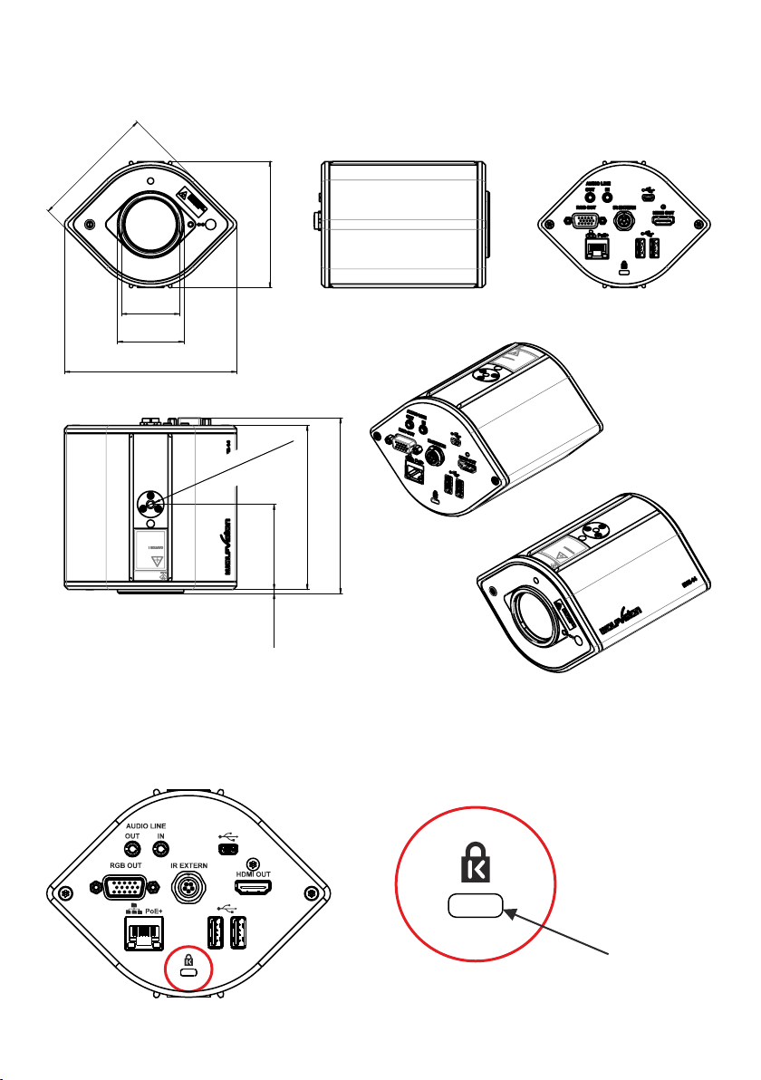
Dimensions
91mm
[3.583"]
[3.602"]
91.5mm
M42x0.75
Ø 48mm
[ 1.89"]Ø
124.55mm
[4.904"]
1/4" -20 UNC
top and bottom
[2.425"]
61.6mm
2.9mm
[0.114"]
[4.673"]
118.7mm
[5"]
127mm
Anti-Theft Device - T-bar lock
The EYE-14 can be fixed with a , so that it cannot be stolen.
Follow the instructions from the cable lock manual.
security cable T-bar lock (Kensington Lock)
®
slot for lock
20
Page 22
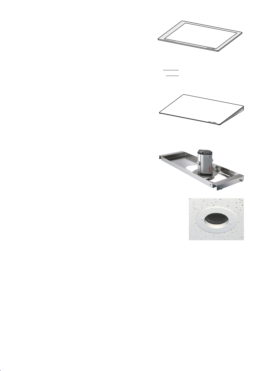
Optional: Lightbox
An lightbox (bottom light) is recommended for dark
transparent material such as x-rays or for very small
transparent material such as slides.
When a lightbox is used, the room light may should be
dimmed or switched off.
When light conditions change, a white balance adjustment
should be performed to compensate the varying color
temperatures of different light sources (see page 10).
Optional: Inclined working surface
The Working plate has crystalline white surface for perfect
reproduction of transparencies and reflecting material like
photos or glossy brochures.
The working plate is 12° inclined in order to avoid reflections.
Optional: Tile Bridge
The Ceiling Tile Bridge is designed to help install the EYE-14
Camera into a standard grid of a suspended ceiling ( 2’ x 2’ or
2’ x 4’).
The Tile Bridge is made of aluminium to insure a light but
sturdy construction. It fits standard ceiling grids in American
and European sizes.
The EYE-14 is attached to the Tile Bridge via a camera
mount. The mount can be rotated 360 degrees and moved
across the Tile Bridge, in order to align the camera with the
working surface.
WolfVision offers lightboxes for x-rays,
slides and transparencies in two sizes:
LB-38: 430 x 359 mm (16.9" x 14.1")
LB-9: 300 x 210 mm (11.8" x 8.3")
Details at: www.wolfvision.com
Size: 320 x 430 mm (12.6" x 16.9")
Height: 10-40 mm (0.4"-1.6") at 12°
A white trim ring is included to dress up the ceiling tile once
the EYE-14 is properly adjusted and in place.
Please note, the trim ring will obstruct the pick-up area if it is
mounted too far away from the lens.
Optional: External Infrared (IR) Sensor
In some rooms, the built-in IR-receiver may . In this case connect the optional external
receiver to the IR-SENSOR plug (#12) and position the IR-sensor somewhere on the ceiling (or in
infrared
the room)
where the users normally point the remote control at.
not be enough
Optional: BYOD Pack and USB WLAN-Dongle (Feature Pack)
For wireless LAN connection use the optional BYOD Pack.
More information at: www.wolfvision.com (Products / Accessories)
Accessories from other manufacturers
Information on some accessories from other manufacturers which can be used with the EYE-14 is available
at: www.wolfvision.com (Products / Accessories)
21
Page 23
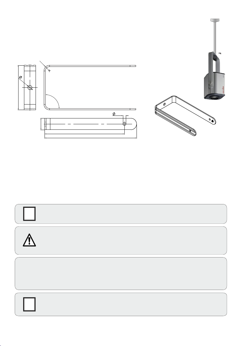
U-Shaped Mounting Clip (Ceiling Mount)
The camera is easily mounted to the ceiling with the supplied U-shaped mounting clip.
In very high rooms, the pick-up size will be too large when mounting the EYE-14 on the
ceiling.
In this case, it is recommended to use an additional ceiling hanger and the supplied
u-shaped mounting clip to suspend the EYE-14 further down from the ceiling.
91
R
12
9
90°
6.5
25
174
200.5
Ceiling Hanger
INSTALLATION
With the 1/4” UNC thread, the EYE-14 can be mounted onto a tripod.
The UNC-threads can be found on the top and bottom sides.
On the front, a filter/adapter lens can be attached: the M42x0.75.
This could be helpful e.g. when the picked-up object would be very close to the lens, a close-up lens can be
attached.
When the EYE-14 is mounted into a housing (or ceiling) make sure to reserve space for the connected
cables (about 50 to 100 mm, depending on the cable used).
To mount the EYE-14 into suspended ceilings, use the optional available tile bridge.
IMPORTANT:
Please give special attention to the specific country regulations for training and
G
conferencing rooms.
Failure to follow instructions can lead to severe injury!
To avoid possible injury, ensure that the ceiling construction is able to support five
times the required camera weight!
For security reasons we are unable to provide fastening equipment for the ceiling mount with
the camera. We request that you acquire the appropriate fastening material for your particular
ceiling construction at your local hardware store. WolfVision will not take liability if substandard
material is used or the installation is done incorrectly and not according to our instructions.
IMPORTANT
Sufficient ventilation is to be provided, otherwise it can result in damage to the
G
equipment.
22
Page 24
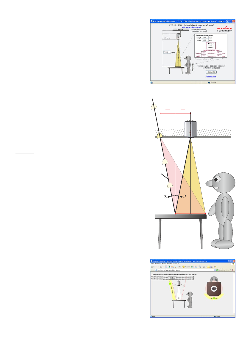
Calculation Program
A very easy method to calculate the exact positioning and the
possible image sizes of the EYE-14 is the dedicated
ca l culat i on prog r am on Wol f Vis i o n's hom e page :
www.wolfvision.com (support)
Recommended Positioning of Light
Please consider light positioning for the EYE-14 carefully.
Mounting the light too close to the unit will cause reflections,
mounting it too far away will cause shadows.
The illustration on the right shows the recommended position
of lighting for the EYE-14. The distance from the center of the
unit to the center of the light should be identical to the
MAXIMUM image size (e.g. vertical image size).
Example: When the maximum vertical size of the pick-up are
(wide) would be 100cm, then the recommended distance of
the light would be also 100cm away from the center of the
camera.
We recommend mounting the light like the position shown on
the right, because here shadows are not too disturbing when
pointing at certain details on a document.
www.wolfvision.com (support)
X
X
2
2
Light
axis
where
the
light
should
be
mounted
EYE-14
Ceiling
Due to the automatic white balance of the unit, it is possible to
use any type of light. WolfVision recommends a diffused light
with more than 400 Lux and a homogeneity of less than 15%
on the working surface.
To minimize reflections, please use the optional inclined
working surface (see page 21).
Flash Animation
A very easy method to find the ideal light position for the
EYE-14 is the dedicated flash animation program on
WolfVision's homepage: www.wolfvision.com (support)
23
X
Speaker
www.wolfvision.com (support)
Page 25
MAINTENANCE
Cleaning
Cabinet: Clean the cabinet by gently wiping it with a soft, lint-free cloth.
LENS: Clean the lens by gently wiping them with a soft, lint-free cloth (do not use a paper tissue!).
Clean by breathing on the lens to create moisture then wipe with lint-free cloth (If not clean, use
special optical cleaner only!).
Never use strong cleaning agents such as acetone or benzene!
These substances can damage the surface and anti-reflex coating!
IMPORTANT
Firmware Upgrades
The firmware (software) of your EYE-14 (including the o ) can easily be upgraded to the
latest version. The firmware update can be done via USB, Ethernet (LAN) or USB stick.
Firmware update files can be downloaded free of charge at www.wolfvision.com (Support)
Updates via USB or Ethernet/LAN can be made with the software vSolution Link by WolfVision.
Updates via USB stick need the firmware file to be placed in the folder root:\WOLFVISION\
(default folder can be changed in the on-screen menu Advanced Settings / USB Settings).
Alternatively, the firmware update can be started in the on-screen menu (Advanced Settings / Device Info),
provided the EYE-14 is connected to the Internet and a nameserver IP address is assigned (Advanced
Settings / Ethernet Settings). By selecting the line ”Check For FW Update”, the EYE-14 checks the
WolfVision server for newer firmware files. Follow the on-screen instructions to start the update process.
n-screen HELP
Infrared Remote Control
Please note that an infrared remote control can only be used up to a certain distance from the unit. Objects
situated between the EYE-14 and the infrared remote control, and weak batteries, interfere with reception.
If the EYE-14 can only be controlled from a close distance, you may need
to change the batteries.
If the EYE-14 cannot be controlled at all with the infrared remote control,
you may need to check the code (see page 5) or to change the batteries.
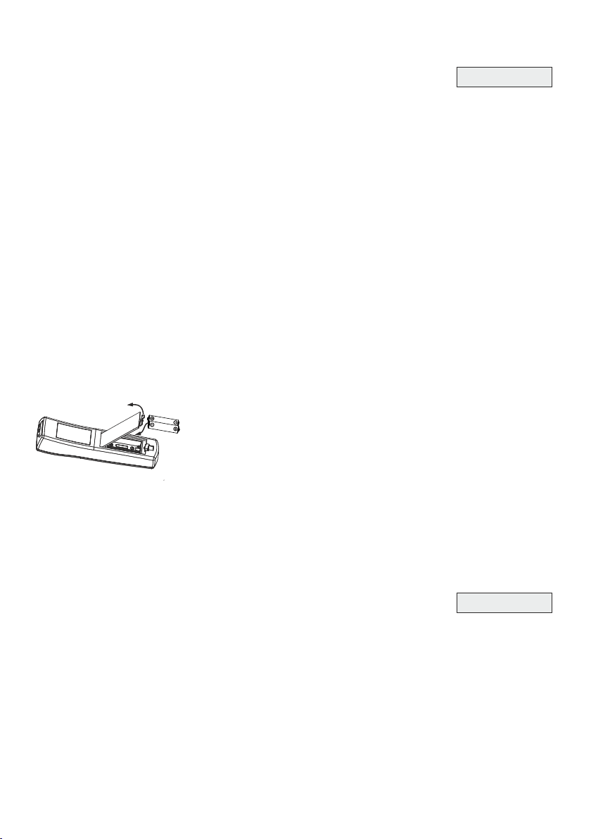
Open the cover on the back of the remote control and replace both 1.5V
AAA (Code LR03) batteries with new ones of the same type.
CAUTION
Risk of explosion if batteries are replaced by an incorrect type.
Dispose of used batteries according to the instructions. Recycle the batteries.
ATTENTION
Il y a danger d‘explosion s‘il y a remplacement incorrect de la batterie. Remplacer uniquement avec une
batterie du même type ou d‘un type équilanent recommandé par le constructeur.
Mettre au rebut les batteries usagées conformément aux instructions du fabricant. Recycler les batteries.
Check the polarity of the batteries!
Packaging / Transportation
Please make sure that you pack up the EYE-14 in the supplied box.
This is very important to avoid damage to sensitive parts of the unit!
24
IMPORTANT
Page 26

Technical Data
Camera / Technology (Signal format)
Pictures per second (as picked up by the camera)
Native (effective Pixels of camera sensor)
Native pixels of image processing
Pixels processed per second
(=effective pixels x frames per sec.)
Color reproduction / precision
Output signals 4:3 and 5:4
Output signals 16:9 and 16:10
WolfVision image processing engine "YSOP1"
Resolution (measured)
Vertical image-frequency
(depending on selected output mode)
Iris (Brightness adjustment)
White balance adjustment
Focus
Center Lasermarker for easy object positioning
On-screen menu and on-screen help
Upgradeable firmware
Lens / Zoom
Lens type
Max. object height on working surface level
Max. pick-up area on working surface level
Min. pick-up area on working surface level
Min. pick-up area on working surface level with
digital zoom
Depth of focus on small object (42 x 33 mm)
Depth of focus on large object (360 x 270 mm)
vSolution Link Software (USB and LAN, for
controlling, image and video capturing and
firmware updates)
Reflection free area on working surface level
User programmable presets
Special working surface for transparencies
Bottom light
Image memory
Seamless cross fading
Built-in digital scaler
Alternative Image display
HDMI output / DVI and DisplayPort output
RGB output
Audio
USB standard / port
Ethernet (LAN)
WLAN (WiFi)
Web Interface
Streaming
Recording
Advanced controlling with professional protocol
Dimensions (L x W x H)
Weight
Infrared remote control
External IR-sensor
Tripod Mount
U-shaped Mounting Clip
Voltage input
Supplied Power Pack
Power consumption
Operating Temperature / Relative Humidity
Warranty
Made in
CMOS 1/3" Progressive Scan
30 frames per second
1920x1080 (=2,073,600), ratio 16:9
1920x1080 (=2,073,600), ratio 16:9
62,208,000, ratio 16:9
SVGA (800x600), XGA (1024x768), SXGA (1280x1024), UXGA (1600x1200)
720p HD (1280x720), WXGA (1280x800), 1080p HD (1920x1080),
internal memory 8GB micro SD + unlimited memory via USB stick
negative image / negative-blue image / black and white image
1x USB 2.0 device port (incl. PTP and UVC) and 2x USB 2.0 host ports
very good colors / sRGB color precision
WUXGA (1920x1200)
yes
Progressive Scan: 30Hz, 50Hz and 60Hz (switchable)
yes, via USB, Ethernet/LAN and USB-stick
zoom lens 56x zoom (14x optical + 4x digital)
depending on installation height
depending on installation height
depending on installation height
depending on installation height
depending on distance to object and intensity of illumination
depending on distance to object and intensity of illumination
included (for 32- and 64-bit Windows and Macintosh)
depending on installation of room light
yes, inclusive audio support / yes, with optional adapter
yes, HDMI, Line In and Line Out (max. 1VRMS@10kOhm)
yes, IP-addressable, 10/100 Mbps
n-draft USB dongle optional (BYOD Pack)
MJPEG, RTP MJPG, H.264 (unicast and multicast)
yes (720p HD, up to 30 frames per second
127mm x 125mm x 91.5mm (5" x 4.9" x 3.6")
2 tripod mounts (on top and bottom, 1/4-20 UNC)
PoE+ (Power over Ethernet Plus) (IEEE 802.3at standard)
multi range 100-240 V, 21W power consumption
adjustable standby power consumption
0°C - 40°C (32°F - 104°F) / 40 - 60%rel
980 lines
automatic and manual
automatic and manual
automatic and manual
yes
yes
wide angle, f= 4.7 - 66mm
TWAIN / WIA compatible
3
optional
optional
yes
yes
yes
yes (IP addressed)
USB and LAN (WLAN)
1kg (2.24lbs)
yes (with laserpointer)
optional, with 10m cable
yes
5 years
Austria (European Union)
Please note: Due to technical improvements all specifications are subject to change!
25
Page 27
CODES - Short Keys
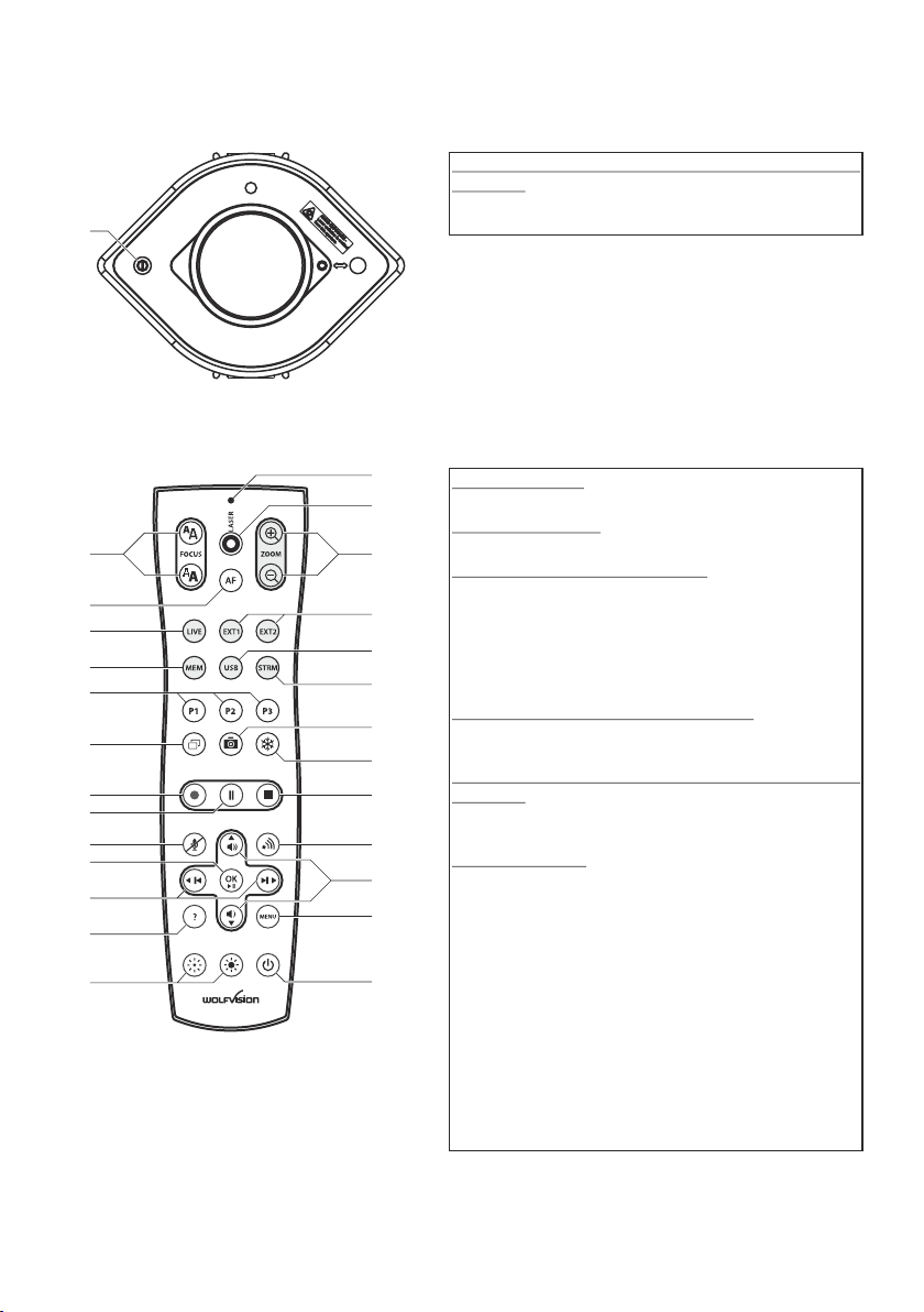
Camera
#4
IR-Remote Control
#31
#30
#29
#28
#27
#26
#25
#24
#23
#22
#21
#20
#19
#32
#33
#34
#35
#36
#37
#38
#39
#40
#41
#42
#43
#44
Resetting the output mode to the default of "XGA
at 60Hz":
Keeping the POWER key (#4)pressed for more than 4
seconds.
Storing presets:
Press the desired PRESET key (#27) for 2 seconds.
Recalling presets:
Press the desired PRESET key (#27) quickly.
Activating the on-screen menu:
Press the MENU key (#43) to activate the on-screen
menu. Use the Navigation keys (#21 and #42) to
navigate and OK key (#22) to select. For the help
function, press the ? HELP key (#20).
For resetting only the selected item press the ? HELP
key (#20)
Activating the on-screen Extra menu:
.
Press the MENU key (#43) and keep it pressed until
the extra menu appears
Resetting the output mode to the default of "XGA
.
at 60Hz":
Keeping the POWER key (#44)pressed for more than
4 seconds.
Change IR code:
Change the IR code in the "Advanced
on-screen menu
Settings / Miscelaneous Settings" and set the "IR
Code" to A, B, C or D (code A is default). To change the
IR code on the remote control, simultaneously
p (#27)
press ress PRESET 1, PRESET 2 keys and the
ZOOM TELE key
(#34). Each time this key
combination is used, the code switches from A to B, C,
D ... A ... in the order given.
For resetting the remote control to code A,
simultaneously p
ZOOM WIDE
ress PRESET 1, PRESET 2 and
.
The LED on the remote control shows the selected
code (it flashes one time for code A, two times for code
B, three times for code C and four times for code D).
26
Page 28
R
CONTACTS
Manufacturer / Worldwide Distribution
WolfVision GmbH
International Distribution Offices
USA
WolfVision Inc.
Duluth Tel: +1(770)931-6802, 877-873-WOLF, Fax: +1(770)931-9606
(Atlanta) E-Mail: [email protected] / [email protected]
Asia
WolfVision Pte Ltd
Singapore Tel: +65-6636-1268
Middle East
WolfVision Middle East
Dubai Tel: +971 (04) 354 2233, Fax: +971 (04) 354 2244
Germany
WolfVision Germany
Japan
WolfVision Co. Ltd.
Tokyo Tel: +81(0)3-3360-3231, Fax: +81(0)3-3360-3236
Canada
WolfVision Canada, Inc.
Ottawa Tel: +1(613)741-9898, Toll free: 877-513-2002, Fax: +1(613)741-3747
United Kingdom
WolfVision UK Ltd.
Maidenhead Tel: +44 1628 509067, Fax: +44 1628 509100
Tel: +1(650)648-0002, Toll free: 800-356-WOLF, Fax: +1(650)648-0009
E-mail: [email protected]
E-Mail: [email protected]
Tel: 0800 / 98 28 787 (Toll Free for Germany)
E-mail: [email protected]
E-mail: [email protected]
E-Mail: [email protected]
E-Mail: [email protected]
Toll free:
, Fax: +65-6636-1269
Internet Homepage: www.wolfvision.com
E-Mail to technical support: [email protected]
Printed in Austria - May 2014
 Loading...