

Page 1
Page 2
PRECAUTIONS
WARNING!
RISK OF ELECTRIC SHOCK
DANGEROUS VOLTAGE INSIDE
Make sure that sufficient air circulation for cooling the unit is possible (ventilation slots on the
left and right side of the unit)
If the Visualizer is not used for a long time turn off the main power switch (#34)!
If there is any abnormality (abnormal noise, smell, smoke etc.) turn the power off immediately
and contact your Visualizer dealer!
USE THIS MACHINE ONLY WITH THE CORRECT VOLTAGE AS
SHOWN ON THE TYPE LABEL !
Do not use a damaged power cord. This may cause short circuits or electrical shocks!
Do not modify the Visualizer or operate it without the cover panel firmly in place, to prevent danger!
DO NOT EXPOSE THE UNIT TO EXTREME HEAT OR MOISTURE !
Do not expose the Visualizer to water, metallic objects or any flammable material.
Do not place liquids or wet objects on the working surface! Put them in front of or behind the
unit and use it as a camera. If you work with wet hands, cover the remote control with plastic wrap!
DO NOT CARRY THE VISUALIZER HOLDING IT ONLY BY ITS MIRROR ARM (#1) !
DURING TRANSPORTATION PROTECT THE UNIT FROM EXCESSIVE SHOCKS !
Avoid installing the Visualizer in environments where there is radiation.
Avoid installing the Visualizer in locations exposed to strong magnetic fields or electrical
currents. This could cause monitor image distortion or damage to the CCD camera.
Precautions about the built-in laser pointer:
AVOID EXPOSURE -
Laser radiation is emitted
from this aperture.
LASER RADIATION - DO NOT
STARE INTO BEAM
650nm, P<1mW, tp<6ms
CLASS II LASER PRODUCT
LASER RADIATION
DO NOT STARE INTO BEAM
CLASS 2 LASER PRODUCT
OUTPUT POWER <1mW
WAVELENGTH 650nm
EN 60825-1 March 1997
FDA accession number:
9912688-00
This device complies with
21 CFR 1040.10 and 1040.11
ETL
FCC
This product is built according to Directive EMC and to Directive electrical equipment.
This equipment has been tested and found to comply with the limits for a Class A digital device, pursuant to Part
15 of the FCC Rules. These limits are designed to provide reasonable protection against harmful interference when
the equipment is operated in a commercial environment. This equipment generates, uses, and can radiate radio
frequency energy and, if not installed and used in accordance with the instruction manual, may cause harmful
interference to radio communications. Operation of this equipment in a residential area is likely to cause harmful
interference in which case the user will be required to correct the interference at his own expense.
2
Page 3

CONTENTS:
Precautions
Connections VZ-17 and VZ-37
Connections VZ-47
Switchable outputs
How the Visualizer works
Basic preparations
Working on the working surface
Focusing
Working outside the working surface
Synchronized Light field
Bottom light / Laser center marker
Working with transparencies
Macro mode
Preset function
Reset function / Power-on preset
Autoiris / manual iris
Video recording
Connecting a computer or video conferencing system
Text enhancement
Freeze function
Special adjustment of LCD- or DLP projectors
Infrared remote control
Automatic lamp changer
Exchanging lamps
Thermostat
Exchanging a fuse
Transportation
Mirror cleaning
White balance adjustment
On-screen menu / Camera menu
Reset of on-screen menu settings / menu-presets
Software upgrades
External synchronization of VZ-37 and VZ-17
Control Connectors (Serial and parallel)
Technical data
Dimensions
Troubleshooting
Page 2
Page 5 IMPORTANT
Page 6 IMPORTANT
Page 6
Page 7
Page 7
Page 8
Page 8
Page 8
Page 8
Page 9
Page 9
Page 9
Page 10
Page 10
Page 10
Page 10
Page 10
Page 11 IMPORTANT
Page 11
Page 11
Page 12
Page 12
Page 12
Page 12
Page 13
Page 13
Page 13 IMPORTANT
Page 14 IMPORTANT
Page 14
Page 14
Page 14
Page 15
Page 15
Page 16
Page 17
Page 18-19
ENGLISH
Detailed settings of the on-screen menu
See on-screen HELP menu of the Visualizers
CONTACTS:
Manufacturer:
Wolf Vision GmbH, Vlbg. Wirtschaftspark, A-6840 Götzis / AUSTRIA,
Tel. ++43-5523-52250, Fax. ++43-5523-52249, E-Mail: [email protected]
Internet Homepage: http://www.wolfvision.com, Technical support by E-mail: [email protected]
American distribution: Wolf Vision Inc., 655 Sky Way, Suite 119, San Carlos, CA 94070 / USA
Tel. (650)802-0786 and 1-800-356WOLF, Fax: (650)802-0788, E-Mail: [email protected]
.
Asian representation: WolfVision Rep office, 27 Woodlands Ind. Park E1, #01-04 Hiang Kie Ind. Bldg. IV, Singapore 757718
Tel. ++65 - 366 9288, Fax: ++65 - 366 9280, E-mail: [email protected]
.
Australian distribution: WolfVision Pty Ltd., P.O.Box 59, West Lindfield (near Sydney), NSW 2070, Australia
Tel. (02) 9410 3388, Fax: (02) 9410 3388, E-mail: [email protected]
.
Canadian distribution: WolfVision Canada Inc., 2998 Route 225, Henryville QC JOJ 1E0
Tel. (450)294-9999, Tollfree 1-877-513-2002, Fax:(450)294-2228, E-Mail: [email protected]
The professional WolfVision Visualizer system was developed and designed by WolfVision in Austria.
The units are "MADE IN AUSTRIA", Patents (examples): US 5027219, FRG 3833908, CH 678576
Printed in Austria Design and specifications subject to change! February 2000
3
Page 4
ATTENTION: Check which Visualizer model you have!
This is a combined user manual for the 3 professional WolfVision Visualizer models: VZ-17, VZ-37 and
VZ-47.
It is noted in each headline if the following chapter applies to all 3 Visualizer models or just to one or two
of these models.
Therefore it is important that you check which Visualizer model you have!
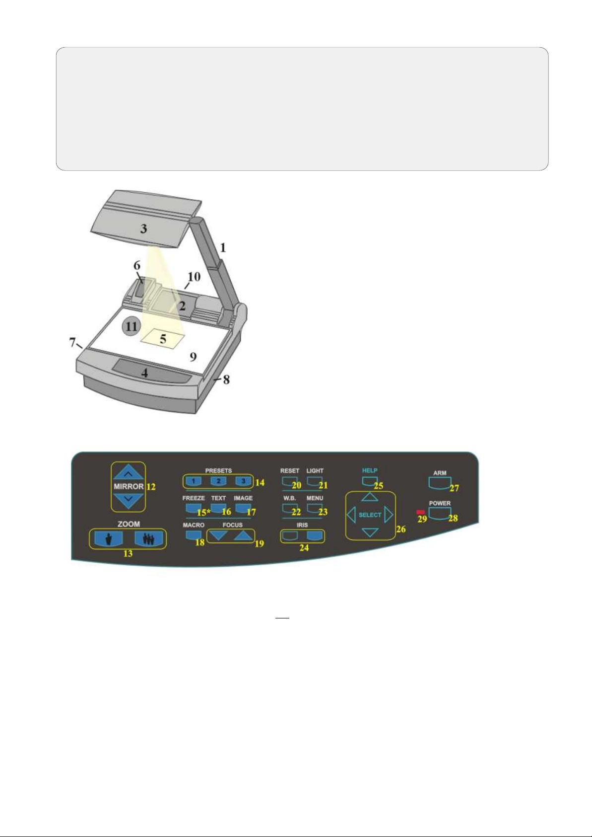
#1 Arm
#2 Base mirror
#3 Top mirror
#4 Control pannel
#5 Synchronized lightfield (Top light)
#6 Remote Control
#7 Ventilation
#8 Air extraction
#9 Working surface with built-in
Bottom light (removable)
#10 Connectors (on the back - see next page)
#11 Lamp exchange cover
(under the removable bottom light)
CONTROL PANEL (all Visualizers)
#12 Upper MIRROR up and down (for scrolling)
(C
cause any harm to the motor of this mirror!)
#13 ZOOM keys (enlargement)
#14 Three user programmable PRESETS
(stored by pressing one of the keys for 4
seconds, recalled by pressing quickly)
#15 Image FREEZE key (VZ-47 only!)
#16 TEXT Enhancement key
(improves the contrast for better readability)
#17 IMAGE (switches the output image on and off)
#18 MACRO (for bigger enlargements - see page 9)
#19 Manual FOCUS adjustment (see page 8)
#20 RESET (activates the Power-on preset)
an also be moved by hand! This does not
#21 LIGHT (switches between "Top light",
"Bottom light" and "Light off")
#22 Manual WHITE BALANCE adjustment
(see page 14)
#23 MENU (activates the on-screen menu
- see page 14)
#24 Manual IRIS (brighter and darker picture)
#25 HELP (activates the on-screen help for
the on-screen menu - This key is only
visible after pressing MENU #23)
#26 SELECT keys for on-screen menu (only
visible after pressing MENU #23)
#27 Motorized ARM up and down
#28 (Standby) POWER on and off
#29 Power LED light (red=off, green=on)
4
Page 5
CONNECTIONS (VZ-17 and VZ-37)
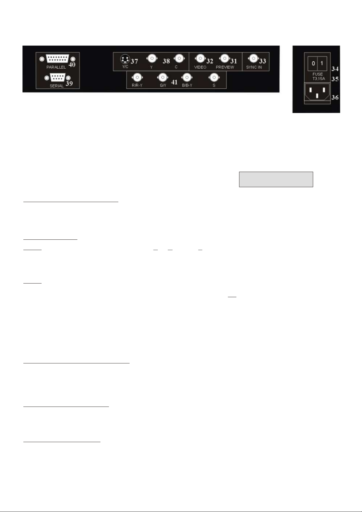
#31 PREVIEW video output
#32 Composite VIDEO output
#33 External SYNC INput (Genlock)
#34 Main POWER switch
#35 FUSE (see page 13)
#36 POWER connection
#37 Y/C (S-VHS) output (details see below)
4-pin connector
(details see below)
(details see below)
#38 Y/C (S-VHS) output (details see below)
2 x BNC connectors
#39 SERIAL port for external remote controlling
#40 PARALLEL port for external remote controlling
#41 RGBS output (can be switched to YUV on
VZ-37 - details see below)
CHOOSING THE RIGHT VIDEO OUTPUT
(of VZ-17 or VZ-37)
Y/C output (S-VHS - #37 and #38)
For live image projection it is recommended to use the Y/C output as the signal passes a sharpness
enhancer. It even looks better than with the RGBS output of the VZ-37. Only the Component output (YUV)
of the VZ-37 offers a better quality than the Y/C-output.
RGBS output (#41)
VZ-37:
VZ-17: On the VZ-17 the RGBS-signal is actually only a converted Y/C-signal. (As the VZ-17 has a 1-chip
The VZ-37 offers a true RGBS-signal. Red, Green and Blue are directly connected to each of
the 3 chips of the camera. As a result this output offers the best color reproduction. This signal is
also recommended for image processing as it is the original (unprocessed) signal.
(On the VZ-37 this output can be switched to YUV - see below)
camera and no 1-chip camera has a true RGBS output). This output is intended for units which do
not have Y/C-input. The quality is better than composite video but not better than Y/C !
IMPORTANT
Most RGB-monitors or projectors use a separate Sync connection. For units without a separate Sync connection
the Sync Signal can be added to the Green-signal.
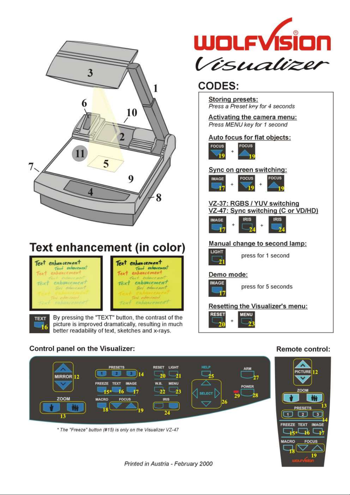
The "Sync on green" function can be switched on and off by simultaneously pressing the following three keys:
IMAGE (#17), FOCUS near (#19), FOCUS far (#19). The factory setting is "Sync on green - off".
If "Sync on green" is switched on, make sure that no separate sync cable is connected - the result
could be a picture with too much green!
Component output (#41 - VZ-37 only)
The RGBS output of the VZ-37 can be switched to Component output (YUV) by simultaneously pressing
the following three keys: IMAGE . (#17), IRIS dark (#24), IRIS bright (#24)
The connections are the following: Red=R-Y, Green=Y, Blue=B-Y
Composite video output (#32)
Only use this output if the display device does not have Y/C or RGBS input. This is the oldest standard with
the lowest bandwith the quality is not as good as with the other outputs.
Preview video output (#31)
This is a composite video output for a control monitor. It's the only output that is not switched off, when
the IMAGE key (#17) is used. Do not use this output for the audience's monitor or projector!
5
Page 6
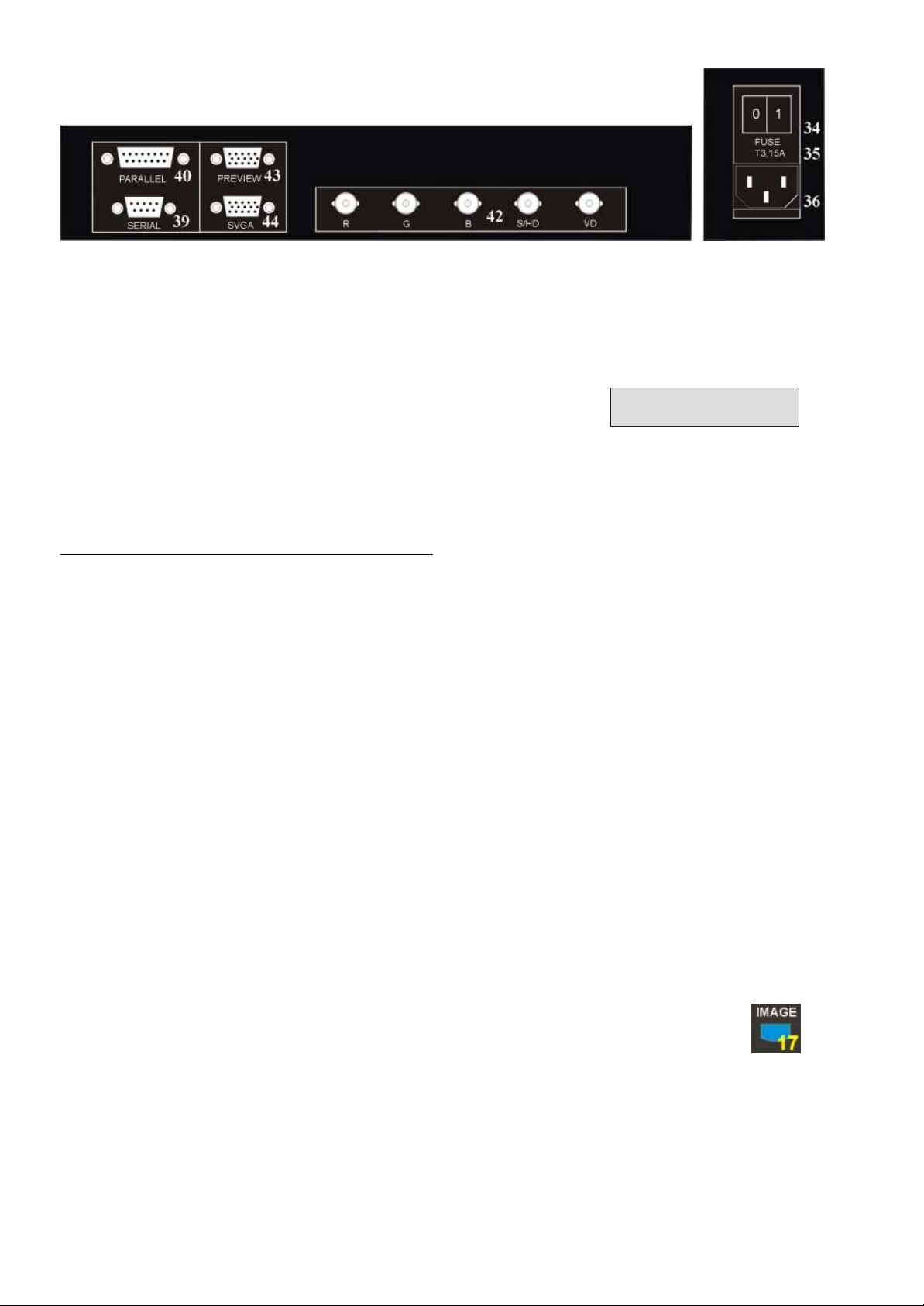
CONNECTIONS (VZ-47)
#34 Main POWER switch
#35 FUSE (see page 13)
#36 POWER connection
#39 SERIAL port for external remote controlling
#40 PARALLEL port for external remote controlling
RGBS OUTPUTS (VZ-47)
The VZ-47 outputs an RGBS-signal with 50 Hz and 31.25 kHz.
This is a DATA-RGBS signal which can be used by most data-projectors or computer-monitors.
However, you can NOT connect the VZ-47 to a video monitor or a video-projector which can not project
computer data (with a resolution of at least 782 x 582 pixels or 31.25 kHz)
#42 RGBS-output (switchable - details see below)
#43 PREVIEW SVGA-output (not switchable - details
see below)
#44 SVGA-output (switchable - details see below)
IMPORTANT
Synchronization of a projector or monitor:
Most projectors or computer monitors adjust themselves automatically when the VZ-47 is connected.
However some projectors don't automatically adjust to the signal output of the VZ-47. As it is not 100%
SVGA compatible. The SVGA standard is 800x600 pixels at 60 Hz and the signal output by the VZ-47
is 782x582 pixels at 50Hz.You may have to go into the setup menu of your data-projector or computermonitor to adjust these settings manually.
The factory-settings of the sync-outputs is HD/VD (i.e. separate horizontal and vertical sync-impulses) and syncon-green off. This format is the same as the one used in the computer-industry so there should be no problems
with the most multiscan-monitors or projectors.
However, if your display-device does not support separate sync-inputs but has only one sync-input (normally
marked with S) you should switch the Visualizer to CSYNC (i.e. the combined vertical- and horizontal-syncimpulses are output on the S/HD-connector). You can switch between CSYNC and VD/HD by pressing the
following three keys simultaneously: . IMAGE (#17), IRIS dark (#24), IRIS bright (#24)
If you want to use sync-on-green you can change between sync-on-green on and off by simultaneously pressing
the following three keys . You can also change this setting in
the camera-menu. When sync-on-green is switched on you need only to connect R, G and B. Monitors which do
not support this mode often display a green picture.
Please note that the sync-outputs are the same on all three outputs (5 x BNC, Preview and RGB). So if you use
multiple display-devices you should use a mode which is supported by all display-devices. Many modern monitors
or projectors automatically detect the sync-mode so they should be able to work with most of the above Visualizersettings. On some display-devices you can also change manually between these modes.
IMAGE (#17), FOCUS near (#19), FOCUS far (#19)
SWITCHABLE OUTPUTS (all Visualizers)
All outputs of the WolfVision Visualizers - except the Preview output (#31 or #43) - are switchable. Use the
IMAGE key (#17) to switch the signal supplied from these outputs on and off. Independently an image is always
output by the Preview output (#31 or #43). This output can be used for a control monitor. A constant sync signal
is supplied to all switchable outputs (even in the image off mode) eliminating monitor image distortions when
switching.
When the output signal is switched off the IMAGE key on the control panel is illuminated red.
6
Page 7
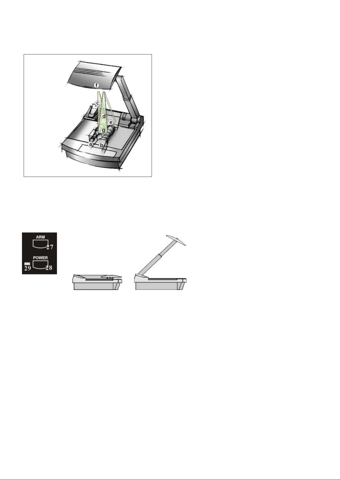
HOW THE VISUALIZER WORKS (all Visualizers)
How it works:
A light projector (a) inside the unit projects a
lightfield (g) the same size as the pick-up area
of the built-in camera via the base mirror (e)
a) light projector
b) camera
c) light path
d) image path
e) base mirror
f) top mirror
g) pickup area /
synchronized
lightfield
and the top mirror (f) onto the working
surface. The image is recorded by the camera
(b) using the same path.
The lenses of the light projector (a) and the
camera (b) are synchronized. Thus the size of
the light field on the working surface changes
when the user changes the zoom range of the
camera.
This scanning and illumination system is a
worldwide patent from WolfVision.
BASIC PREPARATIONS (all Visualizers)
1. Connect the power cable to the unit (#36) and plug it in.
2. Connect a control monitor (if required) to the Preview output (#31 or #43).
3. Connect a large viewing monitor or a projector to one of the outputs of the Visualizer.
For choosing the right output please read the previous pages!
4. Turn the main power switch (#34, on the back of the unit) to "I". The red power indicator (#29) on the control
panel indicates that power is supplied.
5. If the arm is folded down press the ARM key (#27) on the control panel, then the arm comes up automatically.
6. Press the POWER key (#28) on the control panel. The Visualizer now runs the "power-on preset" (=automatic
focusing of an A5 format on the working surface) during which the green LED light (#30) is flashing. As soon as
the green LED light stays illuminated you can start working with the Visualizer.
(The behaviour of the unit once that power is supplied to the unit or after the POWER key is pressed can be
changed in the unit's menu - see page 14 and on-screen help menu)
7
Page 8
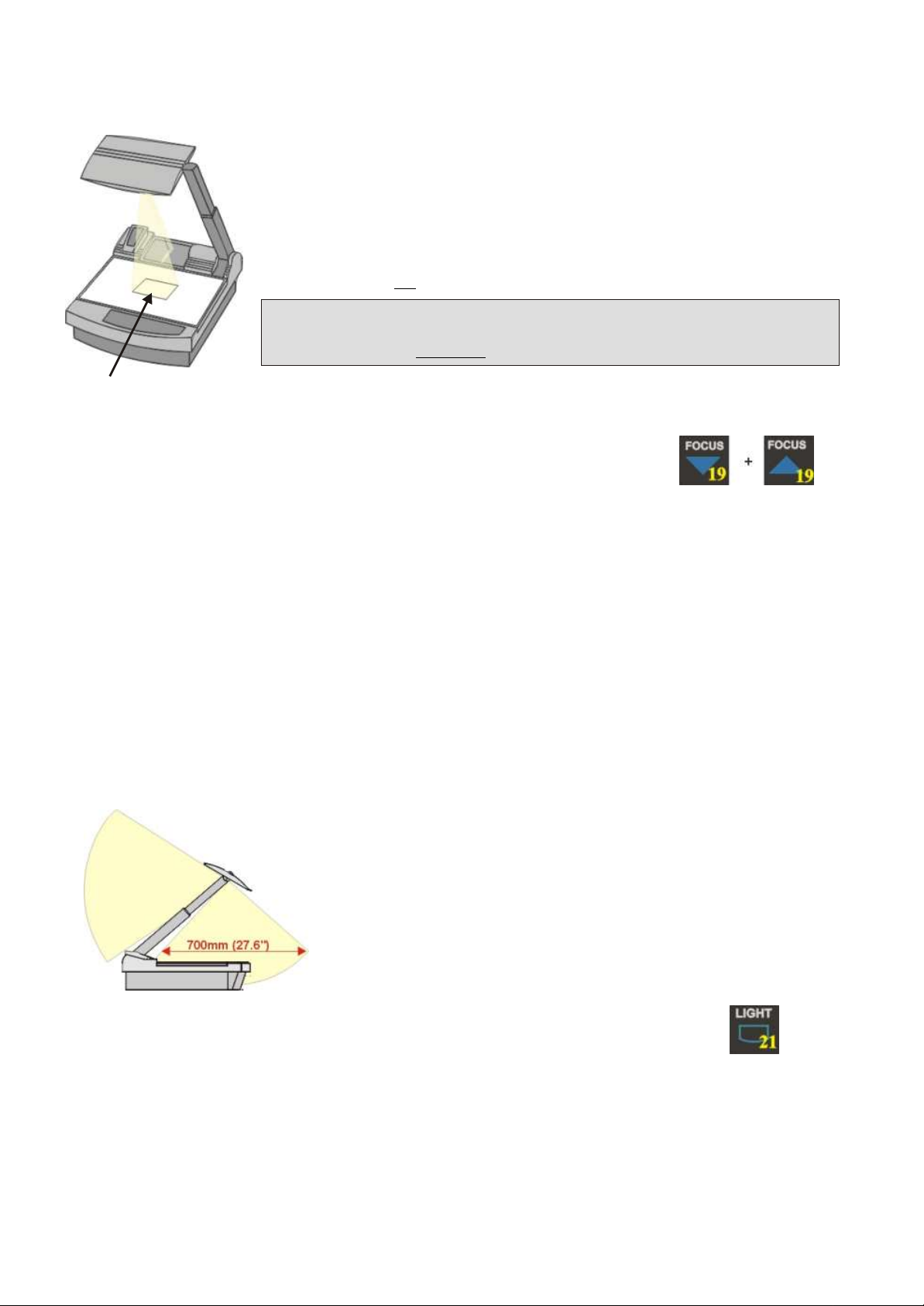
WORKING ON THE WORKING SURFACE (all Visualizers)
1. Place your subject material on the working surface. A synchronized lightfield on
the working surface marks the pick-up area of the built-in camera! Just place your
subject material in the illuminated area.
2. Select the enlargement required with the ZOOM keys (#13).
3. Use the MIRROR keys (#12) on the control panel or the remote control to change
the vertical position of the pick-up area. The upper mirror can also be moved by
hand! This does not cause any harm to the motor of this mirror!
DO NOT TOUCH THE MIRROR SURFACE, AS FINGERPRINTS CAUSE
BRIGHT AND HAZY SPOTS ON THE PICTURE ! ALWAYS KEEP THE
MIRROR CLEAN ! CAUTION: SENSITIVE FRONT COATED MIRROR!
Synchronized
lightfield
4. Adjust the sharpness with the FOCUS keys (#19)
FOCUSING (all Visualizers)
When the Visualizer is turned on the focus automatically adjusts to the working surface level. As a result
it is not necessary to readjust the focus if you are only working with flat material (text, photos etc.).
Furthermore, due to the great depth of focus of the Visualizer it is rarely necessary to readjust the focus.
Only very high objects require a focus adjustment.
If you have misadjusted the focus and want to set it back for working with flat objects just press both
focus keys (#19) on the control panel of the unit (not on the remote control!) simultanously. This activates
the Auto focus for flat objects. (With this function the Visualizer checks the mirror position and optimizes
the focus for the working surface level.)
WORKING OUTSIDE THE WORKING SURFACE (all Visualizers)
For showing 3-dimensional objects with the WolfVision Visualizer, just place them on the working surface
and adjust ZOOM and FOCUS (as mentioned). Due to a special WolfVision lens the object can be up to
25 cm (9.7") in height. If the object is to big for the working surface or if you want to show it from the side
just place it behind or in front of the unit and tilt the top mirror by hand or using the MIRROR keys (#12).
In this way it is also possible to make recordings of subjects in
the room or surrounding area, as with a video camera by just
tilting the reflector head.
to infinity
Due to the great focal range it is possible to show details
in every distance to the unit.
If you want to record people you should turn off the light with
the LIGHT key (#21), so that they are not blinded by the light.
SYNCHRONIZED LIGHTFIELD (all Visualizers)
If the top light of the Visualizer is used (normal working condition) a synchronized lightfield always marks the
pick-up area of the built-in camera on the working surface. The alignment of this lightfield is made for working
on the working surface. Because of the oblique mounting of the camera and the light projector of the Visualizer
the lightfield shifts to the left when the distance between the Visualizer and the scanned object is increased
(when capturing images outside of the working surface). This means that the lightfield no longer exactly shows
the recorded area. In this case switch off the Visualizers top light with the LIGHT key (#21) and work with room
light.
8
Page 9
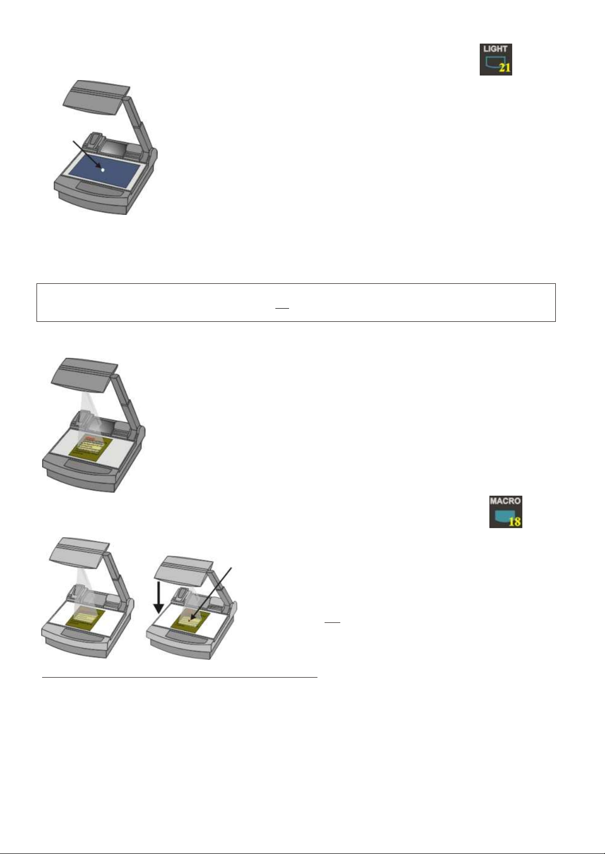
BOTTOM LIGHT / LASER CENTER MARKER (all Visualizers)
The LIGHT key (#21) can be used to switch between:
.
"Top light" (with Synchronized Lightfield)
"Bottom light" (with Laser Center Marker) and
"Light off"
Laser
center
marker
.
The bottom light should be used for dark transparent materials such as x-rays
or for very small transparent materials such as slides.
.
Using the bottom light has the disadvantage that the Synchronized Lightfield of
the top light no longer marks the pick-up area of the built-in camera. However
as a substitute the Visualizers have a built-in Laser Center Marker, which marks
the center of the pick-up area. This can also be used for quick positioning of
objects (especially with big enlargements, like when picking up a slide)
This Laser Center Marker is only visible on the working surface and NOT on the picture the audience sees. For
safety reasons the Laser Center Marker is automatically switched off when the top mirror is tilted to record outside
of the working surface. If required the Laser Center Marker can also be switched off completely in the unit's menu
(see page 14 and on-screen help menu).
Please note that for technical (optical) reasons the laser center marker can not show the exact middle center of
the pickup area in every position of the arm. This is not a failure of the unit! However it is always very close to the
center.
WORKING WITH TRANSPARENCIES (all Visualizers)
The working surface of the Visualizer (#9) has a special crystalline white color,
which is especially designed for perfect reproduction of transparencies.
Even though the professional Visualizers have a built-in bottom light it is
recommended to use the top light for transparencies, because of the
better color reproduction and the advantage that the Synchronized Lightfield
still shows the pickup-area of the built-in camera.
However in these situations it is recommended to use the bottom light:
.
- If the transparency is very dark
- If the transparency is very wavy and causes reflections
- If the room light causes reflections on a transparency
MACRO MODE (all Visualizers)
Laser
center
marker
In the fully extended position of the arm, the smallest pick-up
area is 42 x 33mm (1.6" x 1.3"). When pressing the MACRO
key (#18) the length of the arm is automatically reduced, this
allows for greater enlargements. In the macro mode the
smallest pick-up area is: 30 x 22mm (1.2" x 0.9").
.
There is no loss of resolution in the macro mode, as this is an
optical and not a digital zoom extension.
.
When the macro mode is activated the MACRO key on the
control panel is illuminated red.
Please note that the macro mode has the following limitations:
.
- The depth of focus is not as large as in the fully extended position of the arm.
- The largest pick-up size is only about 42 x 33 mm (1.6" x 1.3").
- When zooming the Synchronized Lightfield stays at a larger size and no longer marks the pick-up area of
the built-in camera. As a substitute the Laser Center Marker (see above chapter) is activated.
If sufficient depth of focus in the macro mode is more important than big enlargements, it is possible to switch the
Visualizer from 12x zoom to 11x zoom in the Visualizer's menu (see page14). The smallest pick-up size in the 11x
macro mode is only 33 x 25mm (1.3" x 1"), but the depth of focus is larger than in the 12x macro mode.
9
Page 10
PRESET FUNCTION (all Visualizers)
WolfVision Visualizers offer the possibility of programming three presets for the functions: Zoom, Focus, Iris,
Light, Image, Text, Macro and Mirror position*. They can be recalled by pressing one of the three PRESET keys
(#14) on the control panel or the remote control.
This function is very useful for example if a user requires one preset for papers on the working surface, one
for working with slides (bottom light) and one for an object placed in front of the unit. During his presentation
the user just has to press one of the PRESET keys key when he changes from one object to the other.
For programming a preset just adjust every function as required and then keep one of the PRESET keys
pressed for more than 4 seconds. The on-screen menu tells you when the preset is stored.
Less than 4 seconds: Recalling a preset
More than 4 seconds: Saving a new preset
* You can select in the unit's on-screen menu if the mirror position should
be stored in a preset or not (see page 14). Default is: YES.
RESET FUNCTION / POWER-ON PRESET (all Visualizers)
When switching on the unit the "Power-on Preset" is activated (=Top light on, Zoom at 210 x 148mm, Focus on
the working surface level, Mirror center). This function can be switched off in the units menu (#23) if required -
see help menu (#25).
This "Power-on Preset" can also be recalled during operation of the unit by pressing the RESET key (#20)
AUTOIRIS / MANUAL IRIS (all Visualizers)
WolfVision Visualizers are equipped with autoiris. That means that the brightness of the camera image adjusts
automatically. Using the IRIS keys (#24) the autoiris function is switched off. In this mode the Iris can be adjusted
manually.
When using the ZOOM keys (#13) the autoiris function is switched on again. Before the iris closes completely,
the Visualizer automatically dims the light.
The standard auto iris level can be set brighter or darker in the unit's menu (#23) - see help menu (#25).
VIDEO RECORDING (VZ-17 and VZ-37 only)
For video recording simply connect the Composite video output (#32)
or the Y/C output (#37) of the Visualizer to the according input of your
video recorder. Please note that the Y/C output offers the better
picture quality than the Composite video output. Connect a control
monitor to the output of the video recorder. The RGBS output (#40)
of the VZ-37 can be switched to YUV for professional videorecorders with component input by simultaneously pressing the
following keys: IMAGE (#17), IRIS dark (#19) and IRIS bright (#19).
CONNECTING A COMPUTER OR VIDEO CONFERENCING SYSTEM
(all Visualizers)
A Visualizer can be used as document- and object-camera for video
conferencing systems. Furthermore it can be used as a 3-D scanner for
computers in order to digitize Visualizer images for image processing etc.
The computer has to be equipped with a frame grabber card or another
video INPUT device.
In order to archive the best picture quality please read the chapter
"Choosing the right video output" for VZ-37 and VZ-17 (page 5)
or "RGBS OUTPUTS" for VZ-47 (page 6).
10
Page 11
TEXT ENHANCEMENT (all Visualizers)
For improving the readability of text, sketches and x-rays press the TEXT-key (#16). This mode enhances the
contrast of the picture. Please note that in this mode the colors are darker than usual. To switch off the text
enhancement mode press the TEXT-key again. While the text mode is activated the TEXT key on the control
panel is illuminated red.
IMPORTANT
FREEZE FUNCTION (VZ-47 only!)
By pressing the FREEZE-key (#15) of the VZ-47 the current image is stored and remains on the projection screen
or monitor. Pressing the FREEZE-key once again switches the Visualizer back to live picture. When the picture is
frozen the FREEZE key on the control panel is illuminated red.
Please note that some LCD- or DLP-projectors also have a freeze function, so if you can not switch back to live
image by pressing the FREEZE-key again, it is possible that the image is frozen on the projector.
SPECIAL ADJUSTMENT OF LCD-/DLP-PROJECTORS
Please note that LCD- or DLP-projectors require some special adjustments for perfect projection of a Visualizer image:
DETAIL / SHARPNESS Enhancers
Nearly all LCD- or DLP-projectors have a built-in sharpness enhancer for video signals. The level of this sharpness
enhancement is adjustable with a setting called DETAIL (on most projectors). Please note that for the readability
of small characters a LOW detail setting for Visualizer images is better!
CONTRAST / BRIGHTNESS
With the standard setting of many LCD- or DLP-projectors the picture is too bright if black text on a white background
is being projected. There are 3 possible ways of correcting this problem:
Option 1: Close the Visualizer's iris slightly with the IRIS dark key (#19). This is the quickest solution but it is
only temporarily, because once you press a zoom key the unit switches back to autoiris and the
picture will be as bright as before.
Option 2: Reduce the standard auto iris level in the units menu (#23) - see help menu (#25) for details. This will
keep the iris level permanently lower than usual. However this has the disadvantage that the output picture
may be too dark for other units connected to the Visualizer (e.g. monitor, video recorder, computer)
Option 3: Reduce the brightness of your LCD- or DLP-projector. Better projectors can store individual brightness
settings for each input. So an ideal setting for the Visualizer input can be made, while keeping the setting
for the other inputs (e.g. computer, video recorder).
To make the ideal LCD-/DLP-projector adjustment for Visualizer projection, we recommend to put a white sheet of
paper with text and some objects with different colors on the working surface. Keep an eye on the readability of the
text and the accuracy of the colors.
In order to check how the actual output signal of a Visualizer looks, we recommend to connect a CTR monitor (not
an LCD monitor!) to the Visualizer and use the monitor picture as reference image.
WINDOW Function (only for certain projectors)
The Visualizers output a picture of approx 752x582 pixels
(depending on model). Most modern LCD-/DLP-projectors
have a NATIVE RESOLUTION of 1024x768 pixels. In order to
display the Visualizer image on the full screen size the
projectors up-calculate the image to their panels pixel size.
Most projectors do this conversion perfectly, however with
some projectors some picture quality is lost in this process.
Image up-calculated to
panel resolution
Image with "window"
function
That is why some projectors have a "Window"-function. With
this function only as
the video picture are used and the image is not "blown up" to
the full panel size.
11
many pixels of the display as required for
Page 12
INFRARED REMOTE CONTROL (all Visualizers)
Please note that an infrared remote control can only be used up to a certain distance to the unit. Objects situated
between the Visualizer and the infrared remote control and a weak battery may interfere with the reception.
If the Visualizer can only be controlled from a close distance or if it
cannot be controlled at all with the infrared remote control you may
have to change the batteries.
Open the cover on the back of the remote control by hand and replace
the two 1.5 V AA batteries with new ones.
If a user works with a number of WolfVision Visualizers simultaneously
each unit can be set to a different infrared code, so up to 4 units can
be controlled individually with their remote controls.
front back (open)
In order to change the infrared codes, first open the 4 screws on the back of the remote control and set the DIPswitches to the required code A, B, C or D (see graphic above). Then press the MENU key (#23) on the control
panel of the Visualizer for one second until the on-screen menu appears. Then go into the "Misc. Settings" menu
and set the "IR Code" to A, B, C or D.
AUTOMATIC LAMP CHANGER (all Visualizers)
WolfVision Visualizers are fitted with an automatic lamp changer. If one lamp fails, there is no need to replace it
immediately, as the automatic lamp changer automatically switches to the second lamp. When the unit changes
lamps there is an on-screen message saying: "Changing lamp".
When switching on the unit the Visualizer checks if both lamps are working. If one lamp fails there will be an
on screen message for a couple of seconds displaying "Change lamp". This prevents a user from forgetting to
change a defective lamp.
If a lamp is not fully defective but worn out and as a result the light output is quite weak, you can switch manually
to the second lamp by pressing the LIGHT key (#21) for 1 second.
EXCHANGING LAMPS (all Visualizers)
1. Turn the unit off (#28) and disconnect the
power cord!
2. Remove the bottom light (#9) by pulling the
two black bolts (situated left and right of the
control panel) to the front and lift up the
bottom light plate.
3. Remove the lamp exchange cover (#11)
by turning it to the right and lifting.
4. Change the lamp (or both lamps)
Before changing the lamp allow it to cool or use
a cloth to avoid burning a finger! When pressing a
new lamp into the socket use a cloth to prevent
fingerprints on the lamp!
Only use 12 V/100 W halogen lamps (socket: GY 6,35), types: Philips 7023, Osram HLX 64625, Ansi FCR,
LIF A1/215 etc. These are relatively inexpensive standard OHP lamps.
THERMOSTAT (all Visualizers)
If the unit gets too hot (improper ventilation or air extraction) a built in thermostat will switch off the light of the
Visualizer. Verify that proper ventilation and air extraction is available and allow the unit to cool.
12
Page 13

EXCHANGING A FUSE (all Visualizers)
Before changing a fuse disconnect the power cable. The fuse (#35) is situated behind a small
lid between the power socket and the main power switch. It can easily be opened with a small
screwdriver etc.
Please make sure that the fuse is put in the right way round (An arrow on the socket indicates
the right direction of the fuse).
The type of fuse is: T 3,15A. Do not use any other type !
Change the fuse for a new one and switch the unit on again. If the fuse fails again contact your Visualizer dealer!
With most Visualizers the fuse never fails during the whole lifetime of the unit.
Left: spare fuse
Right: active fuse
TRANSPORTATION (all Visualizers)
Mirror
protection
Visualizer folded
During transportation put a cushion with a soft cover (like paper) between the mirror and the
working surface - in order to prevent damage to the mirror !
CLEANING (all Visualizers)
Mirror:
out of the focal range). However the top mirror (#3) always has to be kept clean!
W
Normal dry cleaning or cleaning together with breathing a bit on the mirror should be sufficient (If not,
use a special optical cleaner only!)
Please note: Switch off the power before cleaning a mirror in order to make shure that the Laser Center Marker
is off. (The Laser Center Marker is automatically switched off anyway, when the mirror is turned to the outside)
Please note that dust on the base mirror (#2) inside the unit has little effect on the picture quality (as it is
ipe the mirror gently with a soft (!) and lint-free tissue (no paper!).
IMPORTANT
IMPORTANT
CAUTION: Sensitive front coated mirror!
Move the tissue in vertical direction only ! (Horizontal scratches would
cause ugly reflections) Avoid high pressure !
DO NOT USE ORDINARY GLASS CLEANER OR ALCOHOL
- THE RESULT WOULD BE A SLIGHTLY BLUE MIRROR SURFACE !
The glass covering the mirror inside the unit should also be kept clean.
Cabinet: Clean the cabinet by gently wiping it with a soft cloth. Never use strong cleaning agents such as
benzine or alcohol!
13
Page 14
WHITE BALANCE ADJUSTMENT (all Visualizers)
Each time the lighting condition changes, the user should adjust the white balance of the Visualizer's camera, in
order to optimize the color reproduction. The Visualizer's top- and bottom light have the same color temperature
so normally a new white balance adjustment is not necessary when changing from one light to the other, but if
there is also room light or sun light shining on the working surface, the white balance should be adjusted.
Top light: First, zoom in on a white object (for example a white paper) until there is only white on the screen.
Then press the W.B. key (#22).
Bottom light: Turn on the bottom light with the LIGHT key (#21). Remove everything from the working surface.
Zoom to the smallest picture. Then press the W.B. key (#22).
You can adjust the white balance either for the top or for the bottom light and it works well with both lights.
When the white balance adjustment is finished successfully the message "WHITE OK" appears on the monitor
after a few seconds. The new white balance is stored automatically and is preserved even if the power supply
is interrupted.
IMPORTANT
The following chapters are for experienced users only:
ON-SCREEN MENU / CAMERA MENU (all Visualizers)
For standard use of the WolfVision Visualizer it is NOT necessary to go into the Visualizer's menu and change
settings. Inexperienced users should not try to make any adjustments there. That is why the keys for the
camera menu (#26 and #27) are dark on the control panel and not easy accessible.
These keys and the on-screen menu only become visible after pressing the MENU key (#23) for 1 second !
This is to prevent that the menu key is pushed by accident by an inexperienced user.
When the menu appears on the screen, settings of the Visualizer's basic functions
can be made using the 4 select keys (#26). On the Visualizers VZ-37 and VZ-47 it
is also possible to change a great number of settings of the built-in camera.
If you require more information on a function in the on-screen menu just set the
cursor in the respective line and press the HELP key (#25). A detailed description
of this function appears on the screen.
The functions of the on-screen menu are not described in this user manual as the help menu is an integrated
part of the Visualizer's software and checking this information on your Visualizer assures that you get the
right information for your unit.
RESET OF ON-SCREEN MENU SETTINGS / PRESETS (all Visualizers)
The settings in the on-screen menu can be set back to the factory defaults. "Reset" is one item in the on-screen
menu. In case you can not read the menu on a screen you can also set the unit back to the factory defaults by
simultaneously pressing the keys: RESET (#20) + MENU (#23).
Please note that this reset-function does not reset the sync settings of the RGBS outputs or the RGBS / YUV
setting of the VZ-37! (To reset those settings use the key combinations listed on the back of this manual)
The on-screen menu also offers the possibility to store three different menu settings as Menu-presets.
SOFTWARE UPGRADE (all Visualizers)
The software of your Visualizer (including the on-screen help menu) can easily be upgraded to the latest
version. It can be done by connecting a computer or a modem to the RS232 port of your Visualizer.
Please consult your WolfVision dealer or check our website (http://www.wolfvision.com/wolf/techinfo.html).
14
Page 15
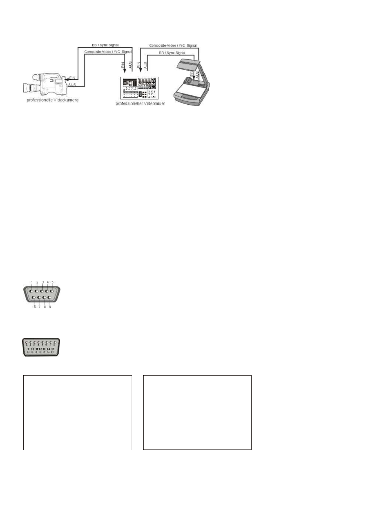
EXTERNAL SYNCHRONIZATION (VZ-37 and VZ-17 only!)
If Visualizer images are mixed and processed (fade-in, fade-out, mix/wipe) with images from one or more video cameras (or
Visualizers) using a special effect unit without TBC (time base corrector), all units connected must be genlocked.
Genlocking is achieved by supplying the same composite video signal (VBS) or black burst (BB) signal to the Extern Sync
input (=Genlock input) of each unit connected.
In order to genlock the WolfVision Visualizer with another video signal, simply connect this signal to the Sync input (#33) of
the Visualizer where a composite video or a black burst signal can be connected.
With a VZ-37 fine adjustment of color-phase (SC) and H-phase can be made in the unit's on-screen menu.
With a VZ-17 it is necessary to open the unit and adjust the settings with a screwdriver on the camera itself. Please leave
this to a technically experienced person, as there is sensitive and potentially dangerous electronics inside the unit!
Start with H-phase adjustment, followed by rough adjustment of "0/180" followed by fine adjustment with SC.
Genlock operation with a playback signal of a video recorder is only possible if the signal is time base corrected via a TBC
device.
CONTROL CONNECTORS (all Visualizers)
Serial port
9-pin D-Sub connector
on unit, male, front side
Pins: 2:RX, 3:TX, 5:GND
Serial protocol
A detailed description of the serial protocol (including status
report and position setting) is available on request from your
WolfVision dealer or can be downloaded from our website:
http://www.wolfvision.com/wolf/techinfo.html.
Parallel port (15-pin D-Sub, 12-24 V)
15-pin D-Sub connector, 12-24V
on unit, male, front side
First Function, Shift key is not activated
1. Relay-Out (closed if the arm is complete down) **
2. Lock Arm (if activated, no arm function is possible)
3. Power ON
4. Power Off
5. Arm Up
6. Arm Down
7. Parallel GND *
8. DC +12 V
9. Light On/Off
10. Zoom Tele
11. Zoom Wide
12. Mirror Up
13. Mirror Down
14. Shift inactive
15. GND
* Parallel GND is the ground for the opto-isolated control inputs. DC GND is the ground for DC + 12 V and also for Video out.
If you want to use DC + 12 V for the control inputs make a connection between DC GND and Parallel GND.
** If the relay is open: Resistor value at least 3k3.
Second Function, Shift key is activated
1. Relay-Out
2. Focus near
3. Focus far
4. Iris open
5. Iris close
6. Image On/Off
Parallel GND *
7.
8. DC +12 V
9. Preset1
10. Preset 2
11. Preset 3
12. Text Enhancement
13. Macro On/Off
14. Shift active
15. GND
(closed if the arm is complete down) **
15
Page 16
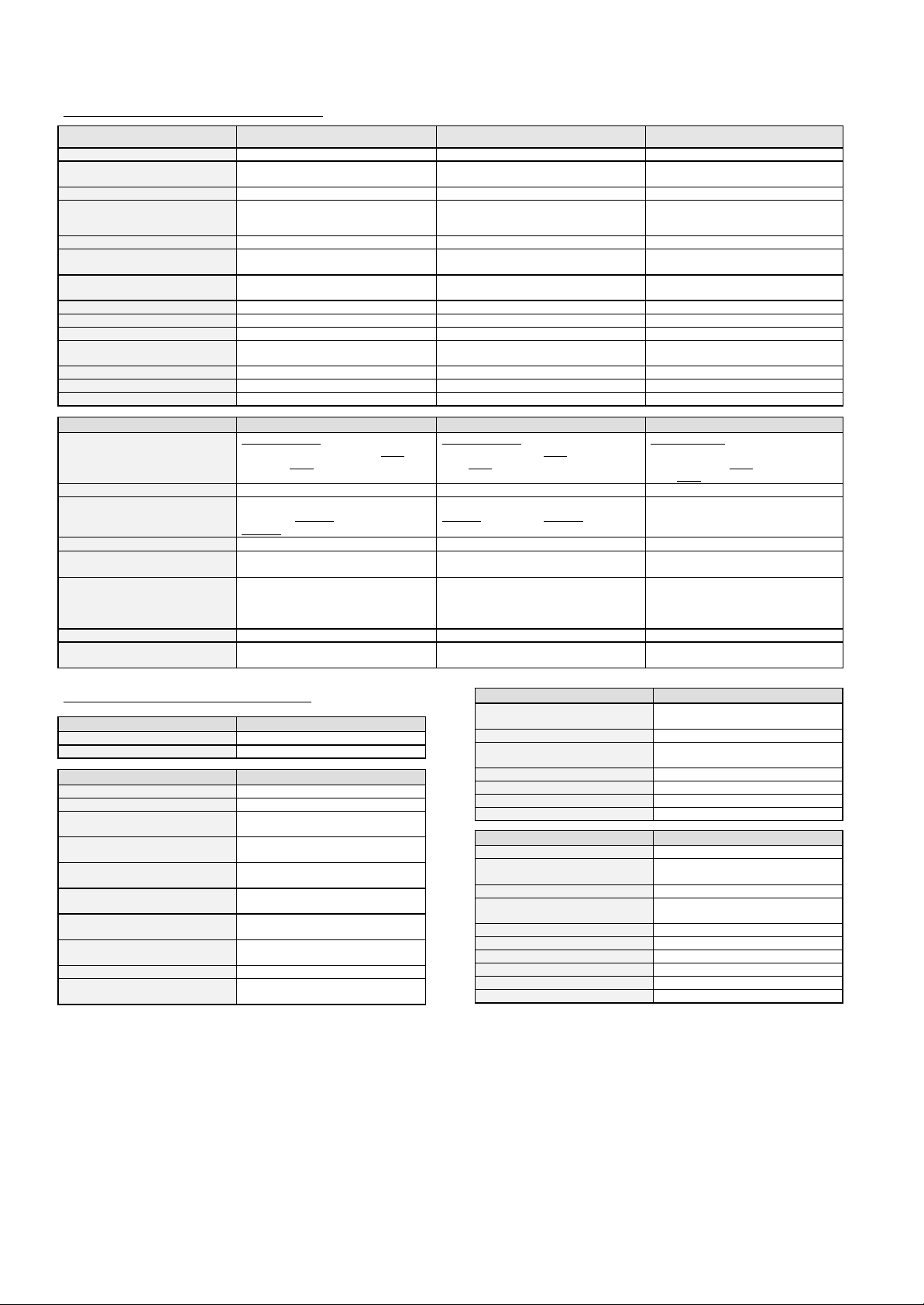
TECHNICAL DATA
Individual features of the 3 models:
Camera:
VZ-17 VZ-37 VZ-47
Built-in camera system: 1 CCD unit - 1/2" interline transfer 3 CCD unit - 1/2" interline transfer 3 CCD unit - 1/2" interline transfer
Effective pixels: 752 x 582 (PAL models)
768 x 494 (NTSC models)
3 times 752 x 582 (PAL models)
3 times 768 x 494 (NTSC models)
3 times 782 x 582
Horizontal resolution: > 470 lines > 750 lines > 800 lines
Vertical resolution: > 400 lines (PAL models)
> 350 lines (NTSC models)
> 420 lines (PAL models)
> 370 lines (NTSC models)
> 575 lines
Color reproduction: very good colors 100% lifelike colors 100% lifelike colors
Signal format / horizontal
frequency / vertical frequency:
interlaced / 15.7 kHz / 50 Hz (PAL) or
60 HZ (NTSC)
interlaced / 15.7 kHz / 50 Hz (PAL) or
60 HZ (NTSC)
non-interlaced / 31.25 kHz / 50 Hz
Images per second: PAL: 50 fields (=half images)
NTSC: 60 fields (=half images)
PAL: 50 fields (=half images)
NTSC: 60 fields (=half images)
50 frames (=full images)
S/N ratio: 50dB 58dB 58dB
Gain control: - automatic / manual 0 to 18 db automatic / manual 0 to 18 db
Electronic shutter: - off / step / manual off / step / manual
On screen menu: for basic settings of the unit for basic settings of the unit and
professional camera adjustments
for basic settings of the unit and
professional camera adjustments
Camera reset function: yes yes yes
White balance: one push white balance automatic/3200K/5600K/manual/o.p. automatic/3200K/5600K/manual/o.p.
Image freeze function: - - yes
Connections:
RGBS-outputs: 1 x Video-RGBS (converted Y/C-
signal): 4 x BNC connectors, RGB: 0.7
Vpp 75
Ω,
Sync: 2 Vpp
1 x Video-RGBS (true RGB signal):
4 x BNC connectors, RGB: 0.7 Vpp
75
Ω,
Sync: 2 Vpp
switchable to component output (YUV)
2 x Data-RGBS (true RGB signal):
5 x BNC connectors and 15 Pin S-
VGA connector, RGB: 0.7 Vpp
75
Ω,
Sync: 2 Vpp
Component output (YUV) - Y, R-y, B-y, BNC connectors Y/C (S-video) output: 4-pin connector and 2 x BNC
connector, Y-signal: 1 Vpp 75
Ω,
C-signal: 0.3 Vpp 75Ω,
4-pin connector and 2 x BNC connector,
Y-signal: 1 Vpp 75
Ω,
C-signal: 0.3 Vpp
75Ω,
-
Composite video output:
BNC connector, VBS 1.0 Vpp 75Ω BNC connector, VBS 1.0 Vpp 75Ω
-
Preview output (outputs a signal
even when image is switched off):
Composite video, BNC connector, VBS
1.0 Vpp 75Ω
Composite video, BNC connector, VBS
1.0 Vpp 75Ω
Data-RGBS, 15 Pin S-VGA connector
Sync input: BNC connector, composite video signal
or black burst (BB), VBS 1.0 Vpp
75
Ω,
H-phase and SC-phase
adjustable (manually)
BNC connector, composite video signal
or black burst (BB), VBS 1.0 Vpp
75
Ω,
H-phase and SC-phase adjustable
(with on screen menu)
-
Parallel port
(for external controlling)
yes yes yes
Serial port with extended serial
protocol including status report:
yes - RS 232 yes - RS 232 yes - RS 232
Common features of all 3 models:
Camera:
Iris: automatic / manual
Text enhancement in color: yes
Optical element:
Optics: two telezoom lenses, f = 2.0
Zoom range (incl. mirror zoom): 12 x optical zoom (full resolution)
Max. pick-up area on working
surface:
360 x 270 mm (14.2" x 10.6")
Min. pick-up area on working
surface:
30 x 22 mm (1.2" x 0.9")
Maximum object height on working
surface:
250mm (9.8")
Max. object size when picked up
outside of working surface:
length, width and height to infinity
Depth of focus on small object
(42x32mm - 1.6"x1.3"):
70mm (2.8")
Depth of focus on large object
(360x270mm - 14.2"x10.6"):
250mm (9.8")
Reflection free area: whole working surface
Synchronized lightfield (for easy
positioning of objects):
yes
Light element:
Light source: 12V / 100W halogen-lamp, 3200
Kelvin (constant light spectrum)
Spare lamp in automatic lamp changer
Built-in lightbox: Size: 380 x 280 (15" x 11")
Light source: 4 x CCFL
Laser center marker: when working with lightbox or macro
Shadow free illumination: yes
Illumination of hollow objects: yes
Disturbing stray light: none
General specifications:
Infrared remote control: yes
Motorized arm: yes - for up/down position and macro
zoom function
Motorized top mirror: yes - for scrolling
Intelligent control panel: yes - only available functions are
illuminated
Power-on preset: on/off switchable
Programmable presets
3 (plus some additional through RS232)
Power consumption: 230 W
Power source: Multi voltage 90-264 V AC, 50/60HZ
Made in: Austria (EC)
Weight: 17 kg (36 lbs)
Specifications and availability subject to change!
16
Page 17
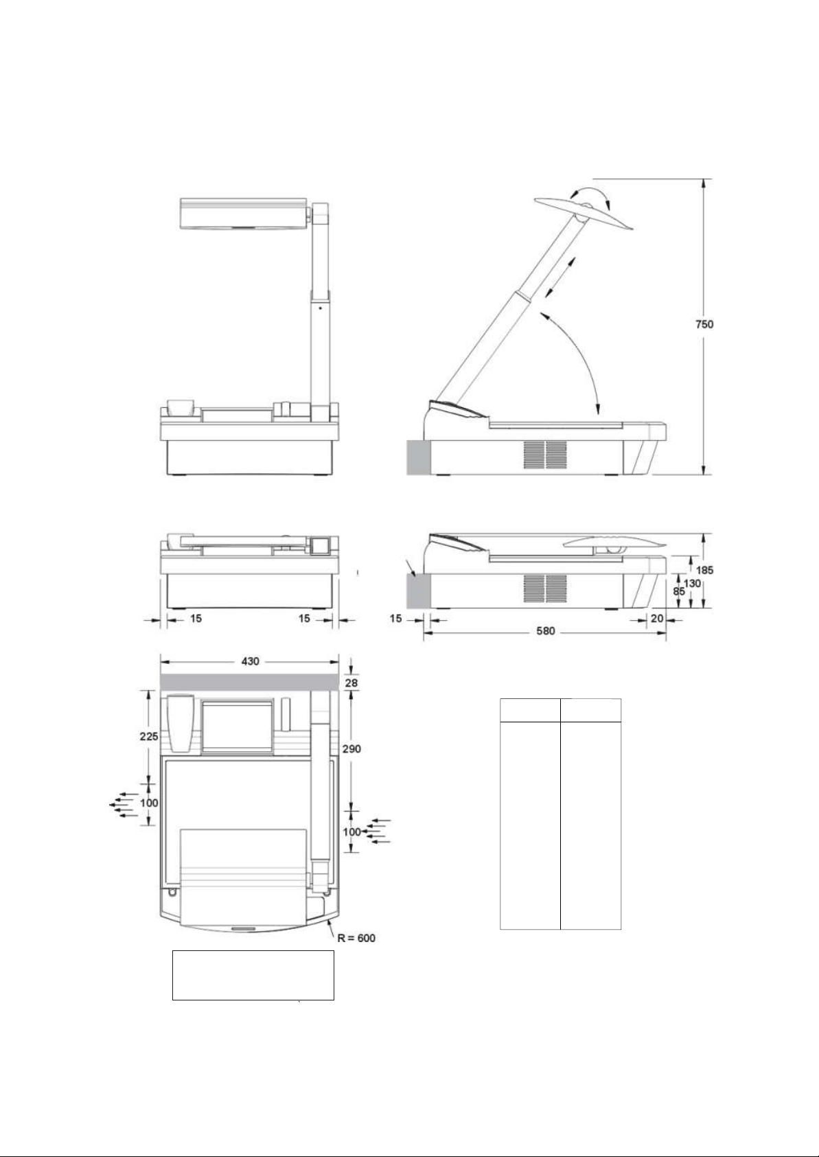
DIMENSIONS (all Visualizers)
Cooling Air
Outlet
IMPORTANT NOTE:
DO NOT BLOCK COOLING
AIR INLET AND OUTLET
Cooling Air Inlet
All measurements in Millimeters
(for inch see list)
mm
15
20
28
85
100
130
185
225
290
430
580
600
750
Inch
0,59
0,79
1,10
3,35
3,94
5,12
7,28
8,86
11,42
16,93
22,83
23,62
29,53
17
Page 18
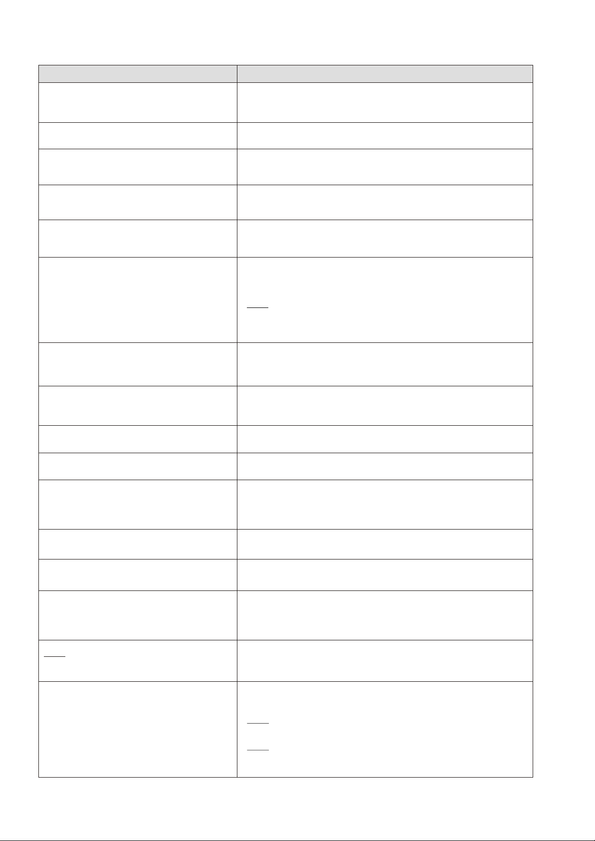
TROUBLESHOOTING
Symptoms: Check points:
No power - Is a power cord connected?
Bright and hazy spots in the picture - Is the top mirror (#3) or the glass over the base mirror (#2) dirty?
Low light - Is the lamp worn out?
No light - Is the light switched off (LIGHT keys #21)?
The left edge of the picture is black / the right
edge of an object isn't illuminated (using the
Visualizer as a video camera)
No monitor picture
Reflections / Glare
- Is the main power switch (# 34, on the back of the unit) switched to "I"?
- Check fuse! (#35)! (see page 13)
If yes clean it BUT BE CAREFUL - (see page 13)
- Are you using the Visualizer with the correct voltage?
- Is the lamp correctly placed in the socket?
- Is the lamp burned out?
- Is the light slot covered?
- Switch off the light with the LIGHT off key (#21) and work with room light.
(This is not a failure of the unit, see page 8 - "Synchronized Lightfield")
- If the IMAGE key (#17) is illuminated red on the control panel, then the
switchable outputs are switched off? - Switch on with the IMAGE key
- Is the IRIS closed? Press the IRIS bright key (#24)
- Check cable connection and input of monitor/projector!
- VZ-47: Check if the monitor or projector is capable to display a SVGA picture with a frequency of 31.25kHz (horizontal) and 50Hz (vertical)
- When using an RGBS output check if the correct Sync-Mode is selected
(see page 5 or 6)
- The working surface of the Visualizer is reflection free (provided that the
material is not very wavy). If there are reflections in the picture it must be
due to room light. Switch off the room light!
Poor picture quality on the projection screen
(using the Visualizer together with a projector)
Picture is too bright (when using an LCD video
projector)
Autoiris does not work
Bad picture quality
False colors
Too much green in the picture
(when using the RGBS output)
No color (B/W only)
VZ-37: Wrong colors or bad picture quality
(using the RGBS / YUV output of VZ-37)
- This is mostly due to bad adjustment of the projector. Connect a monitor to
the Visualizer. If the picture quality is good on the monitor check the
adjustment of the projector.
- An LCD projector should be adjusted for Visualizer projection
see page 11 for details.
- The autoiris function is switched off when using the IRIS keys (#24).
It is switched on again when using the ZOOM keys (#13)
- Check the set-ups and quality of your monitor or projector.
- On VZ-37 and VZ-47, check the camera set-ups in the on-screen menu. If
you are unsure about the settings use the "reset" function in the menu or
use the key combination: RESET (#20) + MENU (#23).
- Adjust the white balance (see page 14)
- NTSC: adjust color phase of monitor or projector
- Use either SYNC ON GREEN or SEPARATE SYNC but not both at the
same time! (see page 5 or 6).
- Check the TV standard of the monitor or projector (PAL/Secam/NTSC)
- Check color adjustment of the monitor or projector
- Check the Y/C cable (if there is color when using the composite video
output, the Y/C cable may be defective)
- Check if the Visualizer and the monitor or video projector are both switched
to either RGBS or YUV. The VZ-37 can be switched to the other standard
by simultaneously pressing: IMAGE, IRIS open and IRIS close.
No stable picture (Sync problems)
- RGBS-output: Check Sync connection. Use either SYNC ON GREEN or
SEPARATE SYNC (see page 5 or 6).
- Adjust V-Hold on monitor or H/V-frequencies on projector or monitor
- VZ-47: Check if the monitor or projector is capable to display a SVGA picture (with a horizontal frequency of 31.25kHz and a vertical frequency
of 50Hz)
- VZ-47: Check if the correct Sync-Mode is selected (see page 6)
18
Page 19
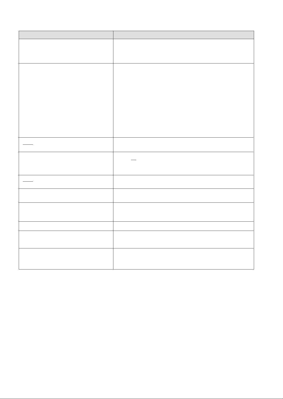
Symptoms: Check points:
Infrared remote control does not work - Change the battery!
The lightfield on the working surface is much
larger than the recorded area.
VZ-47: Two horizontally compressed pictures
appear side by side on the monitor
The Laser Center Marker is slightly right or
slightly left of the middle of the pick-up area.
VZ-47: Too much blue in the Visualizer picture
when projected with an LCD- or DLP-Projector
- If the unit cannot be controlled with the infrared remote control even from
a close distance and with a new battery it may be due to a wrong frequency
(see page 12).
Please note that the lightfield has to be a little bit larger than the recorded
area, otherwise it would not fit in all positions (on the working surface).
However if it is much too big check the following:
- First check if it is possible to adjust your monitor. Many monitors do not
display the whole picture. Some show more of the right side, some more of
the left side etc. Check if there is an UNDERSCAN function - with this
function you can display 100% of the Visualizer picture.
- If you are working with a projector (CTR) check the "blanking" of the
projector
- If you are sure that the lightfield is still much larger than the recorded area
and it is not due to a wrong adjustment of your monitor or your projector,
consult your WolfVision dealer. The size of the lightfield can be adjusted
electronically using a special WolfVision service software.
- The monitor can not display a SVGA-signal. Use a multiscan-monitor
instead
- This is not a failure of the unit. It is optically impossible that the Laser Center
Marker is 100% in the horizontal middle of the picture with every length of
the arm (macro mode on or off). But it is adjusted to be very close to the
middle with every length of the arm.
Adjust the white balance of the LCD- or DLP-projector.
The size of the lightfield does not change when
zooming in and out
It is not possible to record the whole working
surface. The zoom stops at a largest picture of
approx. 42 x 33mm (1.6" x 1.3").
Depth of focus is not as large as usual
Depth of focus in the macro mode in too low for
my application.
Projection picture is frozen
You are in the MACRO mode - press the MACRO key (#18) - see page 9
You are in the MACRO mode - press the MACRO key (#18) - see page 9
You are in the MACRO mode - press the MACRO key (#18) - see page 9
You can change the macro mode from 12x macro to 11x macro in the unit's
menu. The enlargements are not as big as before but the depth of focus is
higher in the 11x macro mode - see page 14 and on-screen help menu.
Check if the projector has frozen the picture (search for a FREEZE key on
the projector or its remote control)
VZ-47: Press the FREEZE key (#15) of the Visualizer
19
Page 20
 Loading...