


STM01018.Rev0
PrintedinexicoM
Part.No48398016.Rev0
READITBEFOREFIRSTUSEOFYOURRANGE THISMANUALCONTAINSIMPORTANTINFORMATION,
MANUAL
INSTALLATION,USEANDCARE
Coversthefollowingmodels:WB30785&WB30985
ESTUFAS EMPOTRABLES
BUILTINRANGES
Ampara los siguientes Modelos: WB30785 y WB30985
INSTRUCTIVO
DE INSTALACIÓN, USO Y MANEJO
LEA CUIDADOSAMENTE ESTE INSTRUCTIVO ANTES DE USAR POR PRIMERA VEZ SU ESTUFA
No. Parte 98016483 Rev. 0
Impreso en México
STM01018 Rev. 0

¡ Felicidades por la compra de su nueva estufa !
Índice |
Página |
|
|
|
|
|
|
Partes y Características |
2 |
|
|
Instalación y Conexión |
3 |
|
|
Funcionamiento |
6 |
Acaba de adquirir un producto desarrollado |
|
Limpieza |
10 |
con las más avanzadas técnicas de diseño |
|
y fabricación. |
|
||
|
|
|
|
Póliza de Garantía |
12 |
Le sugerimos que antes de usar su estufa |
|
Formato de Identificación |
12 |
lea cuidadosamente las instrucciones de |
|
este Manual. Consérvelo ya |
que la |
||
Centros de Servicio Autorizados |
13 |
información contenida en el mismo será |
|
importante para el buen funcionamiento de |
|||
|
|
su estufa durante muchos |
años. |
Partes y Características |
|
||
PARTES Y CARACTERÍSTICAS
Comal de aluminio Capelo de cristal
Parrillas superiores
Quemadores de aluminio Quemadores de 2 posiciones Super quemador Encendido electrónico Interruptor luz de horno Parrilla de horno Termostato de Horno Asador Válvula de corte de gas
TIPO |
WB30785 |
WB30985 |
Antiadherente |
|
|
Con válvula de seguridad |
3 |
|
Alambre |
3 |
|
Fundicion |
|
|
Estandar |
2 |
2 |
Duo Flama |
2 |
2 |
Xpress |
2 |
2 |
Integrado en perilla |
|
|
Auto deslizables |
2 |
2 |
Bidireccional |
|
|
Superior |
|
|
Características eléctricas nominales: |
|
|
127 V |
± 10% 50/60 Hz |
1,0 A Max. |
FABRICADO POR: |
|
|
INDUSTRIAS ACROS WHIRLPOOL, S,A, DE C.V. Unidad Celaya |
||
km 280 CARRETERA PANAMERICANA C.P. 38020, CELAYA, GTO. |
||
|
Tel. 01(461)6185500 |
|
2
|
|
|
|
|
2 |
|
|
|
01(461)6185500 .Tel |
|
280 km |
||
.GTO CELAYA, 38020, .P.C PANAMERICANA CARRETERA |
||||||
|
||||||
Celaya Unidad .V.C DE S,A, WHIRLPOOL, ACROS INDUSTRIAS |
||||||
|
|
|
BY: MANUFACTURED |
|||
.Max A 1,0 |
Hz 50/60 |
10% ± |
V 127 |
|
||
|
|
|
|
Characteristics: Electrical |
||
|
|
|
|
valve gas off Shut |
||
|
|
Superior |
|
Broiler |
||
|
|
|
thermostat Oven |
|||
|
|
directional-Bi |
|
|||
2 |
2 |
|
rack Oven |
|||
out Slide |
|
|||||
|
|
|
|
|
light Oven |
|
|
|
Knob in Integrated |
ignition Electronic |
|||
2 |
2 |
|
Xpress |
|
burner Super |
|
2 |
2 |
Flama Dou |
burner positions 2 |
|||
2 |
2 |
Standard |
burners Aluminium |
|||
3 |
3 |
Iron Cast |
|
grates Top |
||
|
|
Wire |
|
|||
|
|
|
lid Glass |
|||
|
|
valve gas off shut With |
|
|||
|
|
|
|
griddle Aluminium |
||
B30985W |
B30785W |
TYPE |
FEATURES AND PARTS |
|||
|
Features and Parts |
||
|
13 |
Centers Service Authorized |
|
.range your |
12 |
Format Identification |
|
of use the in results best for important is |
|||
|
|
||
information The .manual this in instructions |
12 |
Warranty |
|
the read range, your using Before |
|||
10 |
|
||
.expertise technical latest the |
Maintenance and Cleaning |
||
|
|
||
with manufactured carefully was range This |
6 |
Range Your Use to How |
|
|
|||
|
3 |
Connection Gas & Installation |
|
|
2 |
Features and Parts |
|
|
Page |
Index |
|
|
|
||
¡Congratulations!
3
.outlets multiple or cords extension use not Do • |
|
.outlet wall electrical an near installed |
• |
be must it cord, power a has range your If |
|
.cooktop range the from minimum cm |
• |
61 at it put device, exhaust an install will you If |
|
.range the above directly cabinetry install not Do • |
|
.door oven the open to space |
|
enough with and wind from protected range, |
• |
your for kitchen your in location best the Select |
|
.places their in accessories |
• |
range the put and material packing all Remove |
|
.range this install |
|
must technician Service or technician qualified |
• |
A .responsibility your is installation Proper |
|
.inm 61cm
EXHAUSTDEVICE
Connection Gas and Installation |
|
|
.explosion |
or fire death, in result can so do to Failure |
|
.dangerous is this because |
|
rooms, warm to range your use not Do |
|
|
.flames |
open by contact if ignite may clothes |
|
your clothing; loose wear or burners the by |
|
produced flame the to close too get not Do |
|
.liquids flammable or vapors |
|
other and gasoline material, flammable |
|
of free surroundings range the Keep |
|
|
.use in is |
range while away children keep range; the |
|
with play or use to children allow not Do |
|
Hazard Injury Personal or / and Fire |
|
WARNING |
! |
.use commercial for designed not is It .applications home in only range the Use • |
|
|
.maintenance adequate for Provide • |
.adults unqualified or children by used be to range allow not Do • |
|
.exposure weather against protected is that area an in range your Install • |
|
•Instale su estufa en un lugar protegido de las inclemencias del tiempo.
•No permita que la usen niños o personas que no conozcan su funcionamiento.
•Proporciónele el mantenimiento adecuado.
•Utilice la estufa solo en labores del hogar. No es un aparato de uso comercial.
!ADVERTENCIA
Peligro de Incendio y/o Quemaduras
No permita que los niños usen o jueguen con la estufa; manténgalos alejados mientras está en uso.
Mantenga los alrededores del aparato libres de materiales combustibles, gasolina y otros vapores o líquidos flamables.
No se acerque demasiado a las flamas de los quemadores, ni use ropa suelta, ya que se puede encender y causar quemaduras.
No use su estufa para calentar habitaciones, ya que esto es peligroso.
No seguir estas instrucciones puede ocasionar incendio, quemaduras o la muerte.
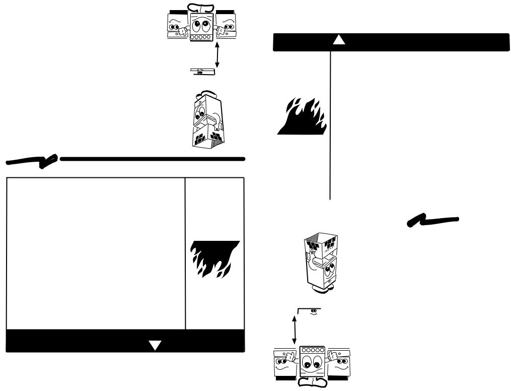
Instalación y Conexión
CAMPANA EXTRACTORA
61 cm mínimo
• La instalación apropiada es su responsabilidad. Un técnico calificado o un técnico de Servicio debe instalar esta estufa.
•Retire los elementos de empaque y coloque los accesorios de la estufa.
•Seleccione la mejor ubicación para su estufa, no debe quedar expuesta a corrientes de aire y debe tener espacio suficiente para abrir la puerta del horno.
•No instale gabinetes o muebles de cocina encima de la estufa.
•Si instala campana extractora, colóquela a 61 cm como mínimo, de la cubierta de la estufa.
•Si su estufa cuenta con accesorios eléctricos, colóquela cerca de un tomacorriente de pared.
•No use extensiones eléctricas o contactos múltiples.
3
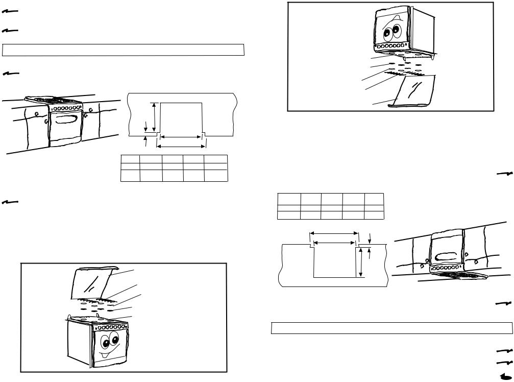
 INSTALACIÓN DE LA ESTUFA EN LA COCINA: • La instalación debe ser realizada por una persona capacitada.
• La estufa está preparada de fábrica para empotrarse Tipo Slide In (deslizándola sobre la cubierta de la cocina).
|
Montaje Tipo Slide - In |
|
|
|||
• Prepare los muebles de la cocina: |
|
|
|
|
|
|
|
CORTES NECESARIOS EN LA |
|
||||
|
CUBIERTA DE LA COCINA. |
|
||||
|
|
|
A |
|
|
|
|
|
B |
|
C |
|
|
|
|
|
|
D* |
|
|
|
30” |
|
510 |
25.0 |
768 |
812 |
|
20” |
|
510 |
25.0 |
509 |
552 |
|
Tamaño |
Dim. A Dim. B |
Dim.C |
Dim. D* |
||
|
de |
|
|
|
|
|
|
Estufa |
|
|
|
|
|
|
|
|
Dimensiones en milímetros |
|||
• Prepare la estufa: |
NOTA: Dimensión D* = Distancia entre muebles. |
|||||
|
|
|
|
|
|
|
-Retire las parrillas, quemadores superiores y sus tapas.
-Deslice la estufa sobre la cubierta de la cocina sin llegar hasta el fondo.
-Conecte la línea de gas como se indica en la página 5 y verifique con agua jabonosa que no existan fugas de gas.
-Realice cuidadosamente las conexiones eléctricas necesarias y deslice la estufa hasta el fondo.
-Coloque nuevamente los quemadores superiores, las tapas de los quemadores y las parrillas.
Capelo de Cristal
Parrillas Superiores
Tapas de Quemadores
Quemadores Superiores
Cubierta Superior
4
Cooktop
TopBurners
BurnerCaps
TopratesG
lassGLid
|
|
|
|
.grates the and caps burner burners, the Replace |
- |
|
|
|
|
|
.countertop the of back the to range the Slide |
- |
|
|
.features) electrical has model your (if cord power electrical the Connect |
- |
||||
|
|
|
|
.solution soap using leaks gas no are |
- |
|
there that verify and 5 page the in shown as supply gas the to range the Connect |
||||||
|
|
|
|
|
.countertop the of |
- |
back the and range the between space a allowing countertop the on range the Slide |
||||||
|
|
.caps burners the and burners top the grates, top the Remove |
- |
|||
.cabinets between Distance = D* Dimension NOTE: |
range: the Prepare • |
|||||
|
|
|||||
millimeters in are Dimensions |
|
|
|
|||
D* .Dim C.Dim B .Dim |
A .Dim |
Size |
|
|
||
Range |
|
|
||||
|
|
|
|
|
|
|
552 |
509 |
0.25 |
510 |
20” |
|
|
812 |
768 |
0.25 |
510 |
30” |
|
|
|
|
D* |
|
|
|
|
|
|
C |
|
B |
|
|
|
|
|
A |
|
|
|
|
|
.COUNTERTOP |
|
|
||
|
|
THE ON NEEDED CUTS |
|
|
||
|
|
|
|
|
cabinets: kitchen the Prepare • |
|
|
|
|
Installation In - Slide |
|
||
|
|
.In Slide as installed be to factory the at prepared is range The • |
||||
|
|
|
.person qualified a by done be should installation The • |
|||
|
|
|
COUNTERTOP: THE ON INSTALLATION RANGE |
|
||
4

5
|
|
|
|
|
.Center Service |
Authorized nearest your at available is kit This |
|||||
98015783 |
98015784 |
|
WB30985 Model |
||
98015783 |
98015784 |
|
WB30785 Model |
||
Gas LP to Gas |
Gas Natural |
|
Model Range |
||
Natural from |
to Gas LP from |
|
|||
convert to Kit |
convert to Kit |
|
|||
|
|
|
.Chart: Gas Conversion |
||
500 7 |
0,046 |
56 |
|
BROILER |
|
000 13 |
0,063 |
52 |
|
VENO |
|
000 9 |
0,052 |
55 |
|
.ALUM SUPER UPPER |
|
700 6 |
0,042 |
58 |
|
.ALUM STD UPPER |
|
BTU/h |
INCHES |
BERNUM |
|
BURNER |
|
CAPACITY |
ETERDIAM |
|
|
inch) oz/squared 44,0( |
|
RIFICEO |
NLUMCO ATERW in 7 PRESSURE |
||||
THERMAL |
RIFICEO |
|
OPERATING ASG TURALNA |
||
500 7 |
0,032 |
66 |
|
ILERBRO |
|
000 13 |
0,043 |
57 |
|
VENO |
|
000 9 |
0,036 |
64 |
|
.ALUM SUPER UPPER |
|
700 6 |
0,031 |
68 |
|
.ALUM STD UPPER |
|
BTU/h |
INCHES |
BERNUM |
|
BURNER |
|
CAPACITY |
ETERDIAM |
|
|
inch) oz/squared (6,36 |
|
RIFICEO |
|
LUMNCO TERAW in 11 |
|||
ALTHERM |
RIFICEO |
PRESSURE PERATINGO GAS LP |
|||
.charts rangeisthesameasshowninthe noleaksandthegaspressureinthe makesurethattheconnectionshave inthepage.13Thetechnicianmust Whirlpool,thephonenumberisshown burnerorifices,callServicioAcrosyoumustreplacethesurfaceandoven •Tousethisrangewithnaturalgas,
forusewithP.L..gas •Thisrangeisadjustedatthefactory
IMPORTANT
|
.pilots and/or |
.illustration the in shown |
orifices of obstruction |
as tubing copper 3/8" the loop |
the avoid to order in it |
should installer the appliance, |
clean should you new, |
the move to easier it make To |
not is installation the If |
|
|
.range |
|
the with provided not is installation for shown aterialm The NOTE: |
|||
adapter .Hex |
|
adapter .hex fitting |
3/8" |
|
pipe brass 3/8" to NPT |
||
fitting |
|
|
|
pipe brass 3/8" |
|
|
|
|
|
valve |
|
|
off shut 3/8" |
|
|
regulator |
gas |
gas |
|
for hose special |
|
||
the reach to length |
|
||
asG |
flexible etallicm |
|
|
Necessary |
|
||
|
or nut type |
|
|
|
.nut type flared 5/8" |
|
|
|
flared 5/8" with |
|
|
|
with pipe copper 3/8" |
|
|
|
pipe copper 3/8" |
|
|
|
|
|
|
|
|
|
range the to integrated |
|
|
|
valve gas off Shut |
|
|
CONNECTION SUPPLY GAS |
|
CONEXIÓN DE LA ESTUFA A LA LÍNEA DE GAS |
|
||
Válvula de corte de gas |
|
|
|
integrado a la estufa |
|
|
|
|
|
Tubo de cobre con tuercas |
|
|
|
cónicas de 9,5 mm (3/8") de |
|
Tubo de cobre con tuercas |
longitud necesaria para llegar |
Regulador |
|
cónicas de 9,5 mm (3/8") |
ó |
al gas |
de gas |
manguera metálica flexible |
|
|
|
para gas |
Llave de paso |
|
|
|
|
||
|
de 9,5 mm (3/8") |
|
|
|
|
Cople-Niple de |
|
Niple de 9,5 mm (3/8" NPT) |
|
9,5 mm (3/8"NPT) |
|
|
|
|
|
a (3/8") cónica |
|
|
|
NOTA: El material mostrado para instalacion no viene con la estufa. |
|
||
Si la instalación no es |
Con el fin de facilitar el movimiento del aparato, |
nueva, limpie los tubos |
el instalador debe hacer una espiral con el tubo |
de cobre, para evitar |
flexible de cobre e instalar una llave de paso |
que se tapen las |
en la línea de suministro de gas, esta llave debe |
espreas y/o pilotos. |
estar fuera de la estufa y accesible a las |
|
personas que la usan. |
IMPORTANTE
•Esta estufa está preparada para funcionar con gas L.P. de tanque móvil o estacionario.
•Para usarse con gas natural ( de tubería) debe llamar a Servicio Acros Whirlpool para cambiar las espreas y hacer los ajustes necesarios, el número telefónico aparece en la página 13. El técnico calificado debe cerciorarse que la conexión no tiene fugas y que la presión de gas en la estufa es que aparece en las tablas.
GAS LP PRESIÓN DE OPERACIÓN |
|
DIAM. |
CAPACIDAD |
2,75 kPa (28 cm Col. agua) |
|
ESPREA |
TERMICA |
QUEMADOR |
ESPREA |
mm |
kJ/h |
SUPERIOR STD. ALUMINIO |
68 |
0,787 |
7 000 |
SUPERIOR SUPER ALUMINIO |
64 |
0,914 |
9 500 |
HORNO |
57 |
1,092 |
13 600 |
ASADOR |
66 |
0,838 |
7 900 |
GAS NATURAL PRESIÓN DE OPERACIÓN |
DIAM. |
CAPACIDAD |
|
1,76 kPa (18 cm Col. agua) |
|
ESPREA |
TERMICA |
QUEMADOR |
ESPREA |
mm |
kJ/h |
SUPERIOR STD. ALUMINIO |
58 |
1,067 |
7 000 |
SUPERIOR SUPER ALUMINIO |
55 |
1,321 |
9 500 |
HORNO |
52 |
1,613 |
13 600 |
ASADOR |
56 |
1,181 |
7 900 |
Juegos de conversión para gas:
Modelo de Estufa
Modelo WB30785 Modelo WB30985
Juego de |
Juego de |
Conversión |
Conversión de |
de Gas LP a |
Gas Natural a |
Gas Natural |
Gas LP |
98015784 |
98015783 |
98015784 |
98015783 |
Este juego está disponible con su Centro de Servicio Autorizado.
5
 Loading...