


KFIL27CXMS

Prepared by: WHIRLPOOL CONSUMER CARE
Home Appliances
PART NO. W10323216
UD-38
KFIS27CXBL
KFIS27CXMS
KFIS27CXMS
KFIL27CXMS
Kitchen Aid 27' French Door
Refrigerators
Models:
March 2010

- ii -
FORWARD
The following service update information is provided to make you more knowledgeable
about Whirlpool, Roper, KitchenAid, Maytag, Jenn-Air, and Amana major appliances.
Service update information is designed for the experienced service specialist. It keeps
you advised of the most recent improvements and product changes, and allows you to
service these products more efciently.
Whirlpool Corporation, Benton Harbor, MI 49022
WHIRLPOOL CORPORATION assumes no responsibility for any repairs made on
our products by anyone other than authorized In-Home Service Professionals.
®Registered trademark/™ Trademarks of Whirlpool, U.S.A., KitchenAid, U.S.A., Jenn-Air, U.S.A.,
or Maytag Corporation or its related companies.
© 2010 All rights reserved.

- iii -
TABLE OF CONTENTS
KITCHENAID 27’ FD AKA TEMPEST ............................................................................ Page 1
Model Number Description ...................................................................................... Page 1
Dimensions .............................................................................................................. Page 2
Product Design Overview ........................................................................................ Page 2
Removing Ice Maker Assembly ............................................................................... Page 3
Wiring Harness Routing Change. ............................................................................ Page 4
Installing Ice Maker Assembly ................................................................................. Page 5
Installing Fascia ........................................................................................................... Page 6
Back Of Unit ................................................................................................................ Page 7
KitchenAid Tempest User Interface ............................................................................. Page 8
Programming - Power Up ........................................................................................ Page 8
Options .................................................................................................................... Page 9
New Use and Care Option ...................................................................................... Page 9
New Substitutions Option ................................................................................... Page 9-10
New Measurements Option. ...................................................................................Page 11
New Photo Display Feature ........................................................................................Page 11
Uploading Photos ............................................................................................ Page 12-13
Upload Progress Screen ....................................................................................... Page 13
Upload Interruptions ............................................................................................. Page 14
Placeholders .......................................................................................................... Page 14
Selecting Specic Photos to Upload ...................................................................... Page 15
Upload Progress Screens ...................................................................................... Page 15
Upload Page .......................................................................................................... Page 16
Uploading Page Progress Screen ......................................................................... Page 16
Deleting Photos ..................................................................................................... Page 17
View Slideshow.. .................................................................................................... Page 18
Tech Sheet ............................................................................................................ Page 19-23

1
*Always refer to Service Sheet and Use and Care Manual for information specic to the refrigerator you are servicing.
KITCHENAID 27’ FRENCH DOOR
REFRIGERATOR WITH ICE AND WATER
IN THE DOOR - TEMPEST II
Model Number Description*
KFIS27CXBL 27’ FRENCH DOOR INW
KFIS27CXMS 27’ FRENCH DOOR INW
KFIS27CXWH 27’ FRENCH DOOR INW
KFIL27CXMS 27’ FRENCH DOOR INW
2
*Always refer to Service Sheet and Use and Care Manual for information specic to the refrigerator you are servicing.
Dimensions
Product Design Overview
Dimensions (Inches)
Capacity 26.630
Depth 35 1/4
Height 70 1/8
Width 35 5/8
Depth Closed Excluding Handles 32 7/8
Depth Closed Including Handles 35 1/4
Depth Excluding Doors 29 1/16
Depth With Door Open 90 Degree 47 7/8
Height To Top Of Cabinet 68 9/16
Height To Top Of Door Hinge 70 1/8
Width of Cabinet Only 35 5/8
Width with Doors Closed 35 5/8
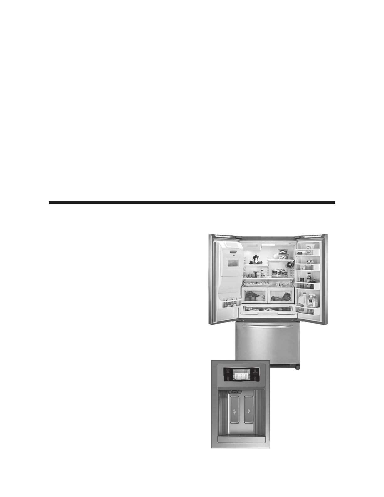
Kitchen Aid 69” Full Depth FDBM•
u 27 ft Capacity
u Energy Star Rated
New UI Dispenser•
u Non-rotating spigot (WER design)
u Victoria ush architecture
u Measured ll
Controls•
u USB port for photo upload
u Resistive touch
u Conversions, Substitutions,
Use & Care
On Door Ice Storage•
u KA graphics and handle color
Exterior Features•
u Contour doors
u Architect II handle
Interior Features•
u Stationary shelves
u Trilogy style crispers with glides
u New temp controlled hippo
pantry with glides
u KA VBL door bins with grippers
u Ramp-On LED lighting
3
*Always refer to Service Sheet and Use and Care Manual for information specic to the refrigerator you are servicing.
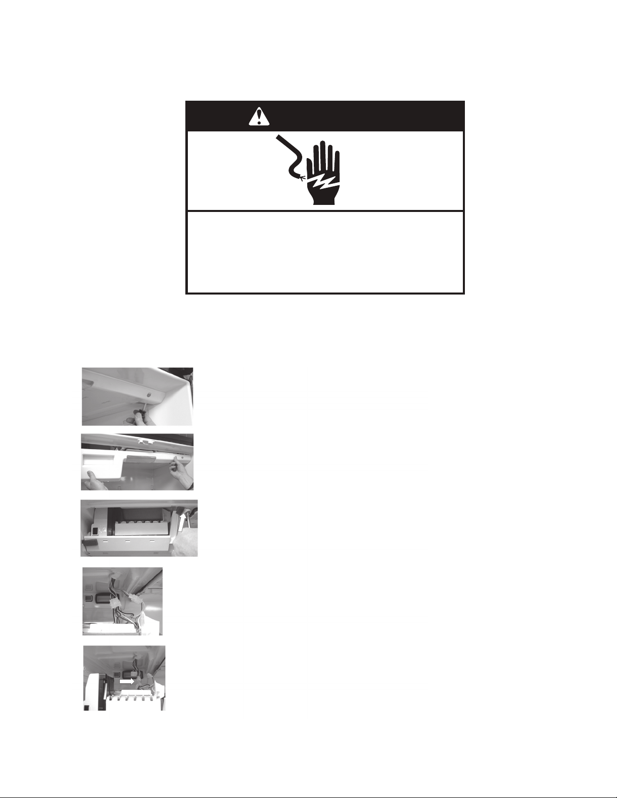
Removing Ice Maker Assembly
Insert a straight blade screwdriver in the slots on the bottom
of the fascia and twist the blade to release.
Pull out the bottom of the fascia and roll up to release the
hooks on the top of the fascia.
Remove the ¼ screw securing the ice maker assembly to
the top of the cabinet.
Move a shelf to the top position on the left RC ladder. Re-
move the ice maker assembly and rest on the shelf.
Disconnect the wire harnesses and remove the
ice maker assembly.
The ice maker wiring harness is now being routed through the top of the cabinet. This
change has made the removal and installation of the ice maker much easier.
WARNING
Electrical Shock Hazard
Disconnect power before servicing.
Failure to do so can result in death or
electrical shock.
Replace all parts and panels before operating.
4
*Always refer to Service Sheet and Use and Care Manual for information specic to the refrigerator you are servicing.
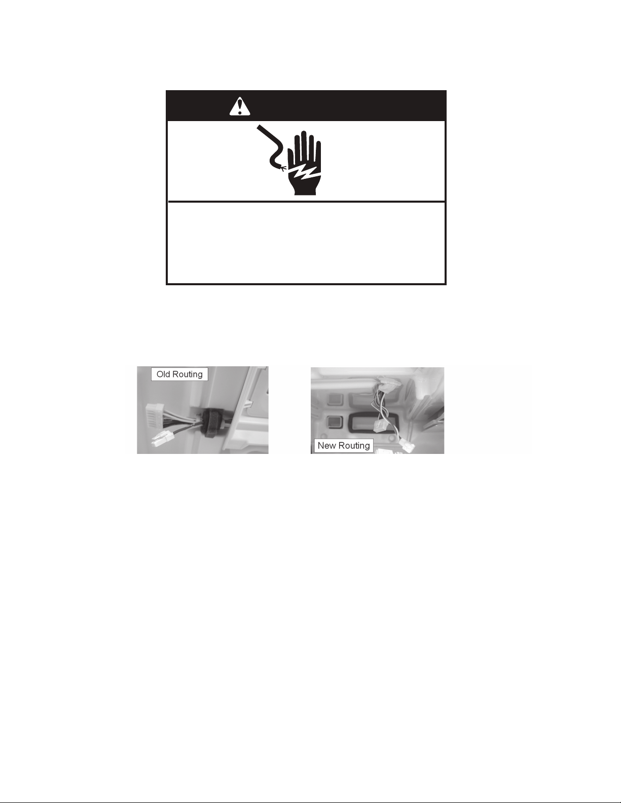
Wiring Harness Routing Change
The elimination of the harness grommet and gasket reduces the opportunity of air
leakage into the refrigerator compartment. This feature will carry over into all 27’ FD
refrigerators beginning March 2010 production.
WARNING
Electrical Shock Hazard
Disconnect power before servicing.
Failure to do so can result in death or
electrical shock.
Replace all parts and panels before operating.
5
*Always refer to Service Sheet and Use and Care Manual for information specic to the refrigerator you are servicing.
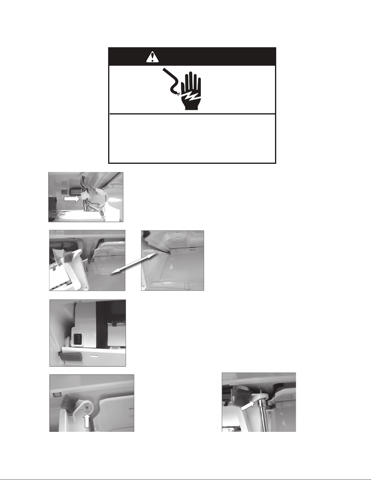
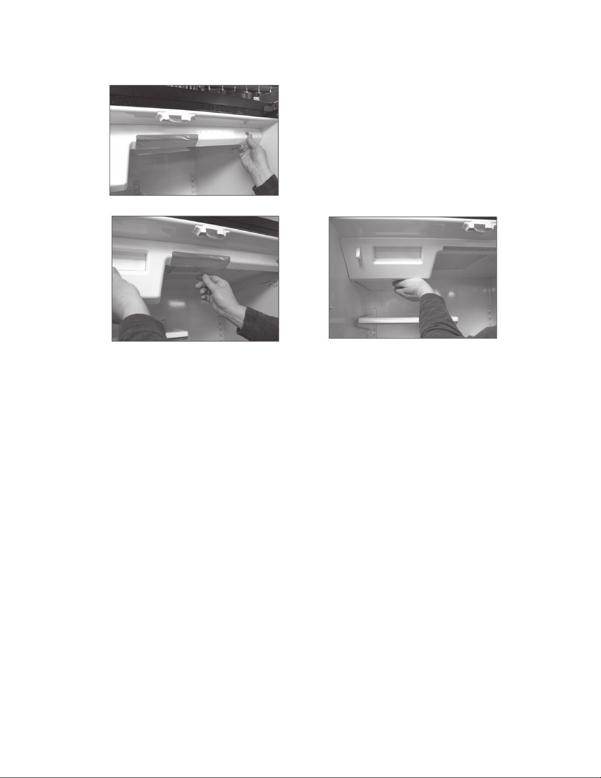
Installing Ice Maker Assembly
Rest the ice maker on the top
shelf. Connect wire harnesses.
Tilt the ice maker assembly
and insert the lip on the right
hand side of the assembly
into the channel on the cover.
After positioning the right side of
the ice maker, raise the left side
and align the hanger bracket on the
cabinet stud.
If the ice maker is
installed properly,
the hole in the ice
maker assembly
should align with
the hole on the top
of the cabinet.
Insert ¼” screw.
WARNING
Electrical Shock Hazard
Disconnect power before servicing.
Failure to do so can result in death or
electrical shock.
Replace all parts and panels before operating.
6
*Always refer to Service Sheet and Use and Care Manual for information specic to the refrigerator you are servicing.
Installing Fascia
Insert hooks in top of fascia into slots
in top of cabinet and roll bottom of
fascia in and up.
Make sure light shield is held in
position by the fascia.
Snap the fascia into place.
 Loading...