Whirlpool ES 4462 IN-1, AKR 191/IX/01, SMS 3460 -1 BR, AKR 191/IX, ES 4462-2 AL User Manual
...GB |
|
|
TABLE OF CONTENTS |
|
|
|
|
|
|
INSTALLATION |
|
PAGE 85 |
||
|
|
|
|
|
ELECTRICAL CONNECTION |
PAGE 88 |
|||
|
|
|
|
|
BEFORE USING THE COOKTOPS |
PAGE 89 |
|||
|
|
|
|
|
ENERGY SAVING TIPS |
PAGE 89 |
|||
|
|
|
|
|
PROTECTING THE ENVIRONMENT |
PAGE 89 |
|||
|
|
|
|
|
PRECAUTIONS AND GENERAL |
|
|||
RECOMMENDATIONS |
PAGE 18 |
|||
|
|
|
|
|
COOKTOP ACCESSORIES |
PAGE 91 |
|||
|
|
|
|
|
MAINTENANCE AND CLEANING |
|
|||
OF CONVENTIONAL ELECTRIC COOKTOPS |
PAGE 19 |
|||
|
|
|
|
|
MAINTENANCE AND CLEANING OF |
|
|||
GLASS-CERAMIC COOKTOPS |
PAGE 19 |
|||
|
|
|
|
|
TROUBLESHOOTING GUIDE |
PAGE 92 |
|||
|
|
|
|
|
AFTER SALES SERVICE |
PAGE 92 |
|||
|
|
|
|
|
84

INSTALLATION
Technical information for the installer
•Check that the appliance has not been damaged in transit.
•Control box dimensions and kitchen unit dimensions are shown in the figures below.
•Attention: for the correct operation of the control box, please make sure that it is in a perfectly central position under the hob.
Mounting the control box (580 mm)
Important: After installation the control box must be shielded from the bottom cabinet by a wooden partition (A).
The partition must not allow the access to installed parts and must only be removed by means of tools.
•Position the brackets in the cabinet, align them to the cabinet front and fix them by means of the 8 screws supplied (B).
•Carry out the electrical connections between control box and cooktop (see chapter “Electrical connection”).
•Embed the control box into the cut-out until the brackets (C) are hooked in the springs.
•Avoid trapping the mains cable when installing the control box.
85

INSTALLATION
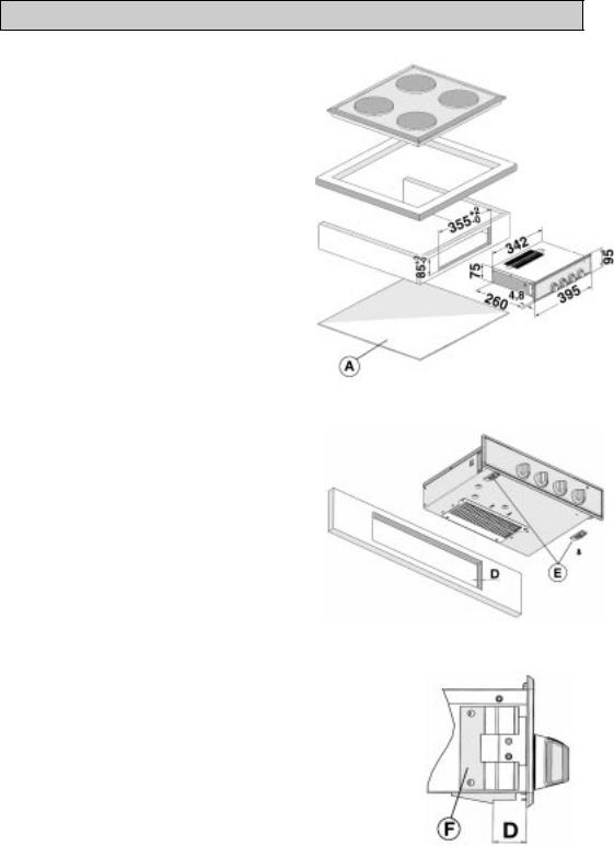
Mounting the control box (395 mm)
Important: After installation the control box must be shielded from the bottom cabinet by a wooden partition (A).
•The partition must not allow the access to installed parts and must only be removed by means of tools.
•Carry out the electrical connections between control box and cooktop (see chapter “Electrical connection”).
•The control box can be installed on a cabinet panel with a thickness (D) included between 16 and 24 mm.
•Before installation check the cabinet panel thickness and adjust spacers (E) as shown in the opposite figure.
•Embed the control box until the two springs (F) and the two spacers (E) hook into the cut-out.
86
 Loading...