

Page 1

WellGate M4 GSM IP Gateway
User Guide
Version: 1.0
Date: September, 2014
Page 2

2
Contents
CH1 Introduction .................................................................................... 4
1-1 Physical Interface ............................................................................. 4
1-2 IP Network connection .................................................................. 4
1-3 Environmental ................................................................................ 5
1-4 Front Panel: LED Indicators ............................................................. 5
1-5 Rear Panel: connections.................................................................... 6
1-5-1 Accessories of WellGate M4 packing ........................................... 7
1-5-2 T y pical application of GSM IP Gateway ....................................... 7
1-6 QUICK SETUP ................................................................................ 9
CH2 Device Settings ............................................................................. 13
2-1 Network Configuration ................................................................... 13
2-2 Device Time Setting ....................................................................... 15
2-3 Device Advance Setting.................................................................. 17
2-4 User Login Setting .......................................................................... 18
2-5 Debug Settings ................................................................................ 19
2-6 Event Notice ................................................................................... 20
2-7 Auto Provision ................................................................................ 21
2-8 SNMP ............................................................................................. 22
CH3 NAT Setting ................................................................................... 24
3-1 DHCP Ser. (DHCP server) .............................................................. 24
3-2 UPnP (universal plug and play server) ........................................... 25
3-3 Bandwidth (Bandwidth Control) .................................................... 25
3-4 URL Filter ....................................................................................... 29
3-5 IP Filter ........................................................................................... 29
3-6 MAC Filter ..................................................................................... 29
3-7 APP Filter ........................................................................................ 30
3-8 Port Filter ........................................................................................ 30
3-9 Port Fwd ......................................................................................... 30
CH4 VOIP Setting ................................................................................. 32
4-1 SIP .................................................................................................. 32
4-2 Audio .............................................................................................. 33
4-3 NAT Traversal ................................................................................. 35
CH5 VOIP Advance .............................................................................. 36
Page 3

3
5-1 SIP .................................................................................................. 36
5-2 Audio .............................................................................................. 39
CH6 Dialing Plan ................................................................................. 40
6-1 General............................................................................................ 40
6-2 Dialing Rule .................................................................................... 41
6-3 Digit Manipulation (DM) ............................................................... 42
6-4 Phone Book..................................................................................... 43
CH7 CO Setting .................................................................................... 45
7-1 CO line ............................................................................................ 46
CH8 SIP Trunk ...................................................................................... 49
8-1 Create SIP Trunk ............................................................................. 50
CH9 Route Plan .................................................................................... 53
9-1 Create Route Plan ........................................................................... 54
CH10 Status .......................................................................................... 56
10-1 Device Status ................................................................................ 56
10-2 Line States .................................................................................... 56
10-3 SIP Trunk Status ........................................................................... 57
CH11 Maintenance ............................................................................... 58
11-1 Firmware Update .......................................................................... 58
CH12 Logout ......................................................................................... 58
Appendix A --- System Recovery ......................................................... 59
Appendix B --- HTTP auto provision ................................................... 61
Page 4

4
CH1 Introduction
WellGate M4 GSM SIP IP Telephony Gateway
WellGate M4 is a 4 lines GSM (WellGate M4) VoIP gateway which includes
1-WAN and 1-LAN (management port) 10/100 base-T network environmen t.
Field-proven quality of Voice communication and broadband acces s network
to makes WellGate M4 to be an ex cellent solut ion for va rious V oIP applicati ons
with GSM network.
1-1 Physical Interface
Ethernet port (RJ-45, 10/100 Base-T)
1-WAN port, for connect to r outer, ADSL modem (ATU-R), or switch
hub directly as well as connect to SIP IP network.
1-LAN port, for PC management or other IP network devices
connecting.
Quad-band GSM module (850M 900M, 1800M and 1900M)
DC power Jack +12Vdc
LED indicate sta tus
Indicates Power, Ethernet, GSM Line, and system status
1-2 IP Network connection
IPv4 (RFC 791)/IPV6 (RFC 2460)
IPv6 Auto C onfiguration (RFC 4 86 2)
MAC Address (IEEE 802.3)
Static IP
DHCP Client (RFC 2131)
PPPoE
DNS Client
TCP/UDP (RFC 793/768)
RTP/RTCP (RFC 1889/ 1890)
IPV4 ICMP (RFC 792)/ IPV6 ICMP (RFC 4443)
TFTP Client
VOIP VLAN Support (802.1q/802.1p)
HTTP/HTTPS Server
QoS Support
Support IPV4 only, IPV6 only or d ual stack mode
Page 5
5
1-3 Environmental
Actual Dimen sion: 19-inch chassis, 1U high, 11 CM depth
Weight: 2.3kg (One unit with pack in g)
Operating Temp. & Humidity
- Temp.: 0℃~45℃ (32℉~113℉)
- Humidity: 1 0%~8 5% relative h umidity, non-condensing
Storage Temp. & Humidity
- Temp.: 0℃~55℃ (32℉~131℉)
- Humidity: 1 0%~95% relative humid ity, non-condensing
AC to DC Power Adaptor:
- INPUT: AC100V-240V, 50/60Hz
- OUTPUT: DC 12V, 3.0A
Regulatory Compliance: FCC (Part 15, Class B) & CE
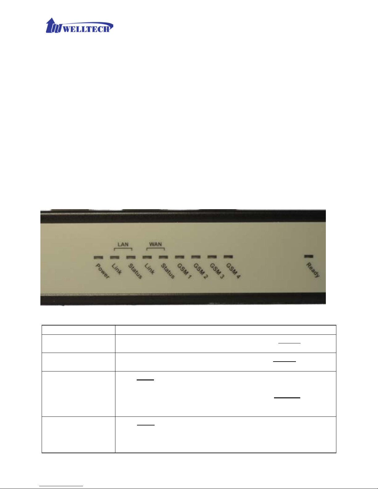
1-4 Front Panel: LED Indicators
Figure 1-4-1 front panel
LED
Description
Power
When the power adapter is connec ted, the Power LED will
light up green.
Ready
When system is startup successfully, the Ready LED will
light up green.
WAN
This Link LED will light up green when the gateway’ s WAN
port is phy sically connec ted to the public in ternet. When
data is transmitted through this port, the Status LED will
flash green.
The default IP of WAN port is 10.1.1.3.
LAN
This Link LED will light up green when the ga teway’ s LAN
port is physically connected to a local network ( Refer to
Rear Panel section in page nu m ber for location of LAN
port). When data is trans m itted through this p or t, the
Page 6
6
Status LED will flash green.
The default IP of LA N por t is 192.16 8.123.123.
GSM 1 to 4
The status LED for GSM line 1-4. It will light up amber
orange when the GSM line is engaged in a conversation. It
will flash fast ambe r orange when there is an
incoming call. GSM LED turns OFF when line is idle .
ATTENTION:
The LED of GSM line w ill flash s lowly when the SIM card
is not effective or SIM card was not inserted.
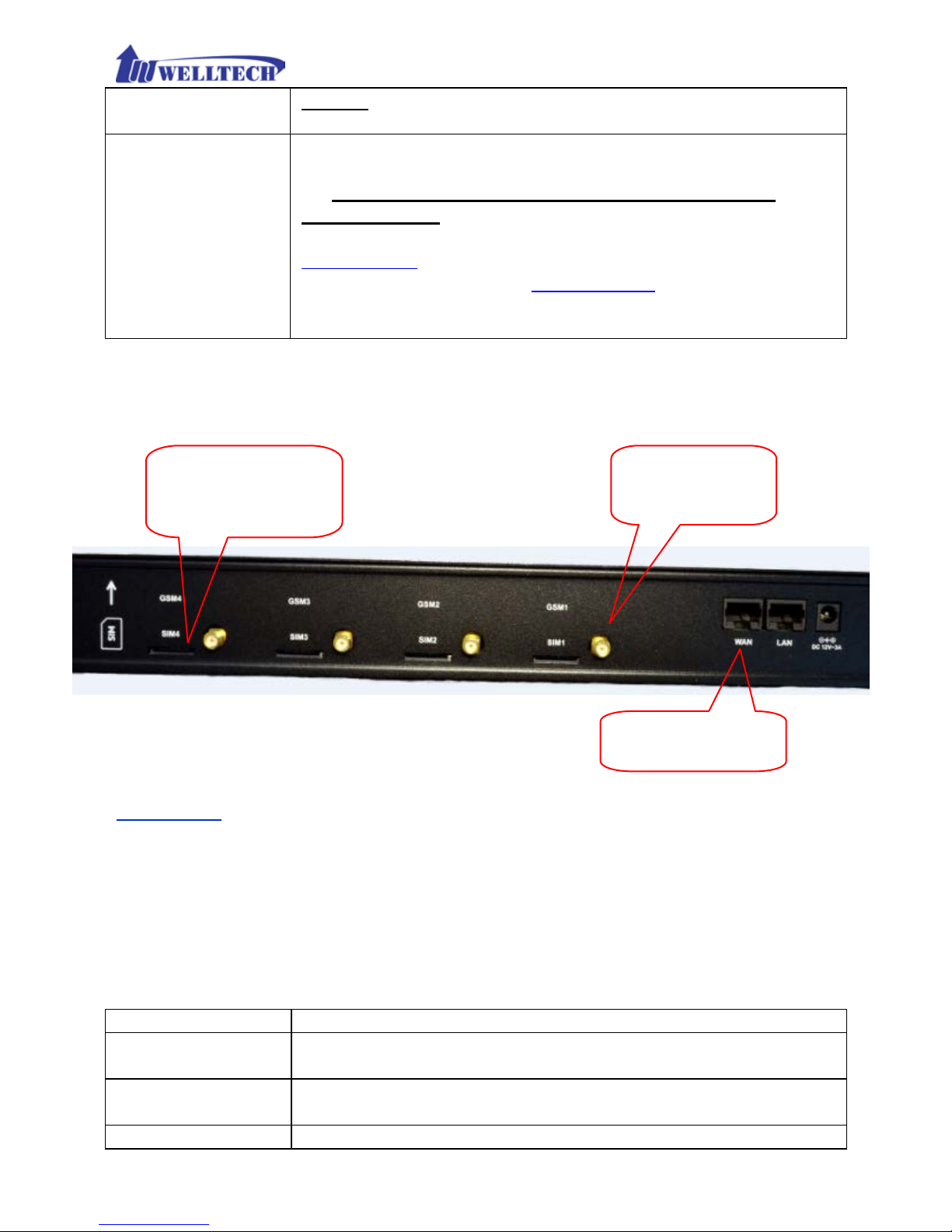
1-5 Rear Panel: connections
Figure 1-5-1 Connection rear panel for WellGate M4
Attention:
1. Please turn OFF elec tric 12 Vdc power wh en y ou want to rem ove or insert
SIM card from WellGate M4.
2. Once you insert SIM card to WellGate M4 while electric 12Vd c is still ON,
please visit we bpage c onfigur ation at CO Line Selec t one CO Lin e ID
(GSM)
Reset GSM Module to Reset it an d activates th is GSM featu re.
3. To remove SIM card from card slot, simply press SIM car to eject and
remove it from card tray.
Item
Description
GSM Line 1 - 4
There are 4 slots to in sert SIM card and attachable
antenna connectors.
LAN
10/100 Base-T RJ-45 socket for LAN por t, con nec ts t o PC
for management pu r pose .
WAN
10/100 Base-T RJ-45 socket for WAN p or t, connects to
Attachable
antenna connect o r
GSM Line 1.
Follow this dir ection
to insert SIM card.
GSM Line 4.
Connect W AN port
to SIP IP network.
Page 7

7
SIP IP network.
DC 12V
The power sock et, input AC 100V~240V; output DC12V,
3A
1-5-1 Accessories of WellGate M4 packing
When you receive WellGate M4 GS M packing, please check the f ollow in g
accessories.
1. WellGate M4 m a in units x 1 unit,
2. Antenna x 4 pcs,
3. AC to DC/3A Power a da ptor x 1 pcs,
4. AC cable x 1pcs,
5. 19-inch chasses mount on Relay Rack brackets x 2 pcs.
1-5-2 Typical application of GSM IP Gateway
1. W ellGate M4 can integrate with IP-PBX to c onnect with local PSTN netw ork
via GSM cellular base station (CBS). For legend connection with PSTN
network, fix ed land lines were often used. Therefore, one FXO gateway or
E1 gateway needs to install between local PSTN network and IP-PBX office.
Thanks to GS M IP gatew ay, the installation job is easier and more f lexible
than before. Th e follow ing diagram in dicates this connection example.
1.WellGate M4
main units x 1pcs
3.AC to DC +3A
power adaptor x1
2.Anten n a x 4 pc s
4.AC powe r
input cable
5.Rack mounted
brackets x 2 pc s.
Page 8

8
2. The alterna tive application of GSM gateway is to regi s te r to IP Telephony
Service provider’s soft Switch in order to tran s it GSM incoming ca ll to
remote IP devices or international call.
Page 9
9
1-6 QUICK SETUP
Note:
Please use Windo ws OS with IE 8.0 web browser or above
version to configure GSM M4 gateway webpage. Welltech
products don’t support other Web Browser such as FireFox
or Google chrome.
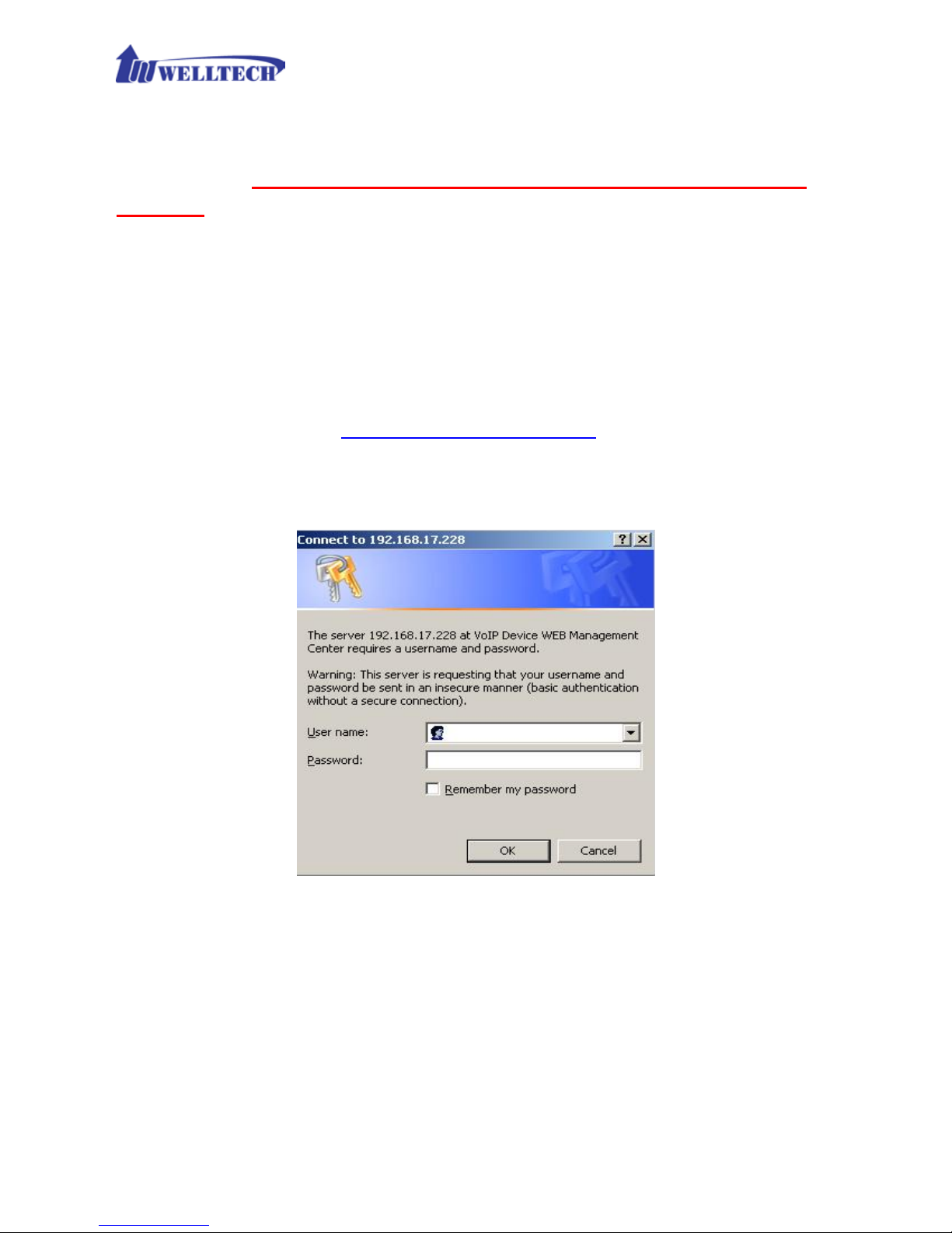
Login :
Setp1:
Setup the administr a tive PC’s IP address to be same as WellGate M4
and connect the Ethernet cable into WAN o r LAN port. Start IE8.0 (or later
version) to navigate WellGate M4 web management system by typing the
default URL which is http://192.168.123.123
(through LAN port) or
http://10.1.1.3 (through WAN port). The screen will display User Name
and Password (the default user id is root a nd user password is root). (See
figure 1-6-1 web access)
Fi gure 1-6-1 web access
Step 2: After login, the screen shows the Home page of WellGate M4. (See
figure 1-6-2 Network configure-1)
Page 10
10
Figure 1-6-2 Network configure-1
Change Defa ult IP Network:
Step 3: After successfully login to the system, we nee d to change the network
configuration. Click Device Setting --> Network to setup the service
network interface (WAN) parameters. Enter the IP address, subnet mask and
default gateway or selected to “DHCP” or “PPPOE”. Apply the change by
clicking Apply button as figure below to save changes (See Figure 1-6-3
Network con figure-2).
Note: If Gateway WAN port was set up in the 10.x.x.x IP segment, please make
sure to keep the LAN por t IP segment as 192.168.x.x in order to avoid from
conflicting betwee n them.
Page 11
11
Figure 1-6-3 Network configure-2
Change Defaul t Ti me se tti ng:
Step 4: When re-login to the new IP address, th e next step is to setup the
system time zon e. Click Device Setting --> Time to setup the system ’s date
and time. Enter the current NTP server, time z one and daylight savin g
parameters. Apply the change by clicking Apply button to save changes. (See
figure 1-6-4 Time setting)
Figure 1-6-4 Time setting
Modify SIP Account Parameter:
Step 5: The next step is to add a SIP trunk for V OIP calling. For WellGate M4,
it is necessary for VOIP calling. Click SIP trunk and new to create the SIP
trunk in details. Select one of 4 trunk ID and enter those SIP par a m eters .
Apply the change by clicking Apply button to save changes. (See Figure 1-6-5
SIP Trunk)
Page 12

12
Figure 1-6-5 SIP Trunk
Soft Reset WellGate M4:
Step 6: A fter modify basic s etting. I t is required to restart WellGate M4. Click
Maintenance --> Maintenance --> Quick-Reset or Reboot to take effect.
Apply the change by clicking Apply button to save changes. (See Figure 1-6-6
Quick-Reset)
Figure 1-6-6 Quick-Reset
Check WellGate M4 Registered St a tus:
Step 7: After Quick-Reset or reboot.
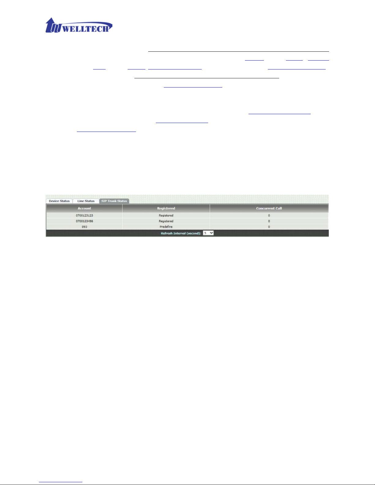
Click Status --> SIP Trunk Status to check whether registered or not. (See
figure 1-6-7 SIP tr unk status)
Figure 1-6-7 SIP trunk status
Through the above settings, the WellGate M4 should be able to do the
following:
1. From GSM n etwork incoming ca ll, the caller will hear a dial tone which was
generated fr om W ellgate M4. Then, the caller can dial a VOIP SIP number
and it will use th e setup SIP Trunk 1 to mak e SIP call out. (2 stage dialing)
2. From VOIP SIP incoming c all, WellGate M4 designate GS M Line will be OFF
hook and dial number to GSM BTS network. (1 stage dialing). Note that
the SIP Trunk must carry DNIS number for G SM line to dial to GSM base
station immediately with 1 S ta g e D ia ling.
Page 13

13
CH2 Device Settings
From this settin g category, all devices related parameters can be found here.
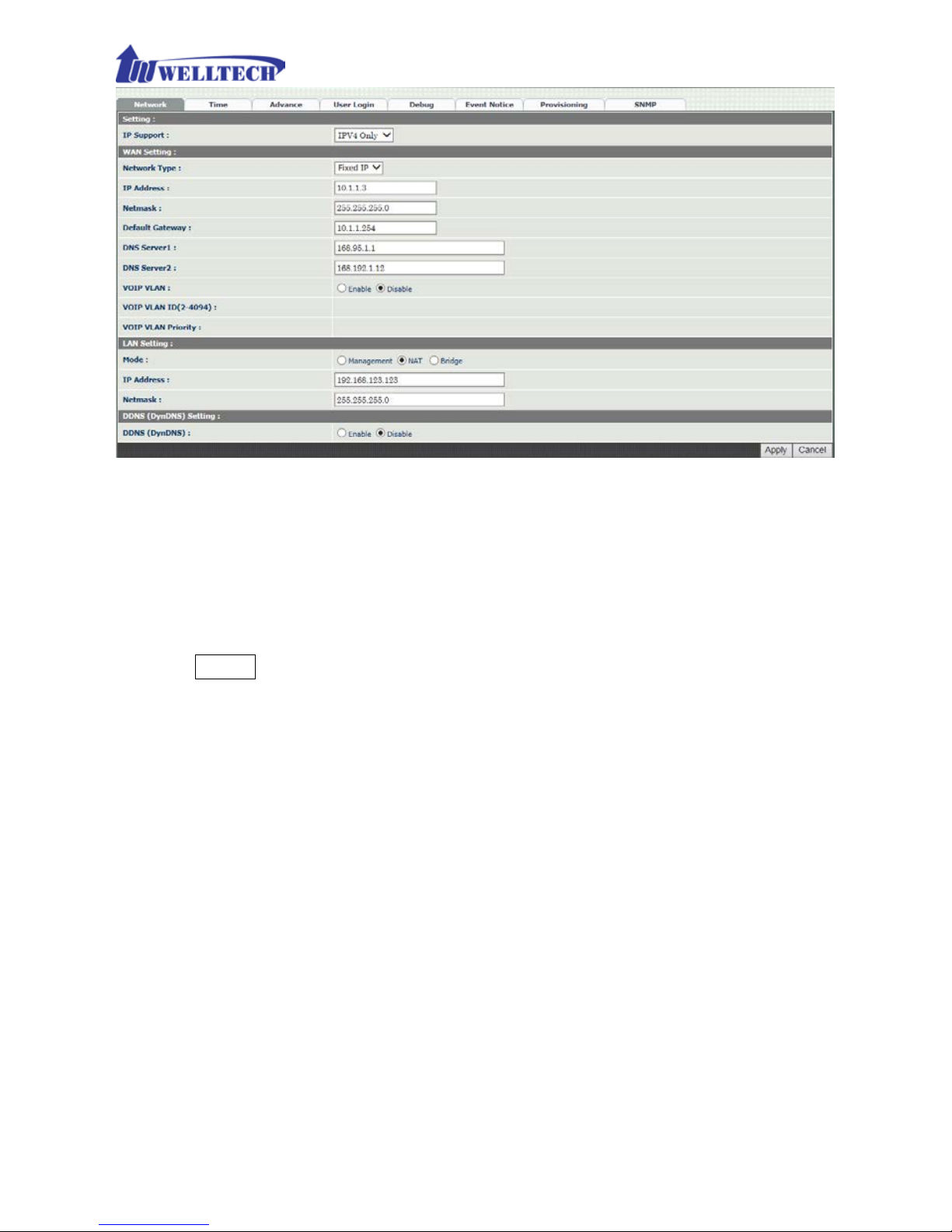
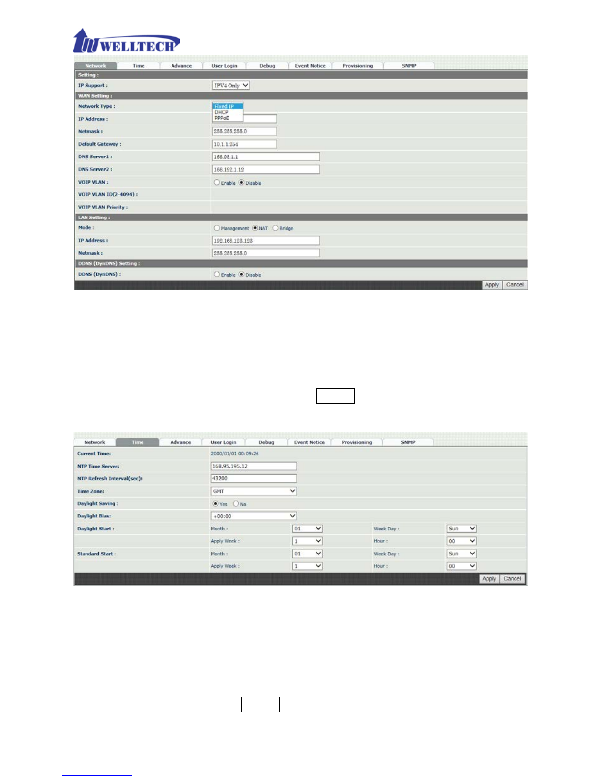
2-1 Network Configuration
> Network
Figure 2-1 network setting
Parameter Description:
Setting:
IP Support: IPv6 or IPv4 stack to be suppor ted
. There are three options:
IPv4 Only, IPv4/IPv6 or IPv6 Only. The default setting is IP v4.
WAN Settin g:
WAN por t wa s used to con nect to S IP IP networ k. F or in stanc e, us e WA N port
to register to SIP soft switch, SIP Server or IP-PBX.
Network Type: It supports Fixed IP, DHCP or PPPoE.
IP Address: IP address to be entered if Fixed IP was selected.
Default Gateway: Default gateway to be entered if Fixed IP wa s
selected.
DHCP Tag (optio n 60): To enter Vendor class identif ier if needed.
DHCP Tag (option 61): To enter Client identifier if needed.
DNS Server1: Primary DNS Server IP address.
DNS Server2: Secondary DNS Server IP address.
VOIP VLAN: Enable VOIP VLAN or not. When this was enabled VOIP
VLAN, the WAN port can be only accessed by VLAN. If it is requir ed to
Page 14

14
access webpage of WellGate M4, please use LAN port to access webpage
configuration.
VOIP VLAN ID(2-4096): The VLAN ID to be used if VLAN was enabled.
Note: the default WAN IP address is 10.1.1.3.
VOIP VLAN Priority (0-7): The VLAN priority to be used if VLAN was
enabled. The number 7 has the highest priority.
LAN Setting:
Management mode: This LAN port is used for management purpose,
not used for SIP register or netw or k data routing.
NAT mode: DHCP server is the function on the LAN port. The LAN port
features DHCP server . If one computer network device was connected
to LAN port, it will receive one IP address.
IP Address
: This is LAN por t IP address. (Please set up 192.168.x.x IP
address to LAN port if your W AN port is usin g 10.x.x.x IP segmen t in
order to avoid from conflic ting between them )
Netmask: The subnet mask IP of LAN port.
Bridge mode: At this mode, both WA N and LAN ports are c onfigured to
Switch/Hub features. When you want to access WellGate M4 via LAN port ,
please use WAN port IP address instead.
Note: The default LAN IP address is 192.168.123.123
DDNS (DynDNS) Setting :
DDNS (DynDNS): Enable or disable dynamic DNS feature.
Domain Name : Enter Domain Name of DDNS Server.
User Name: Enter your use r name
Password: Enter your password
Page 15
15
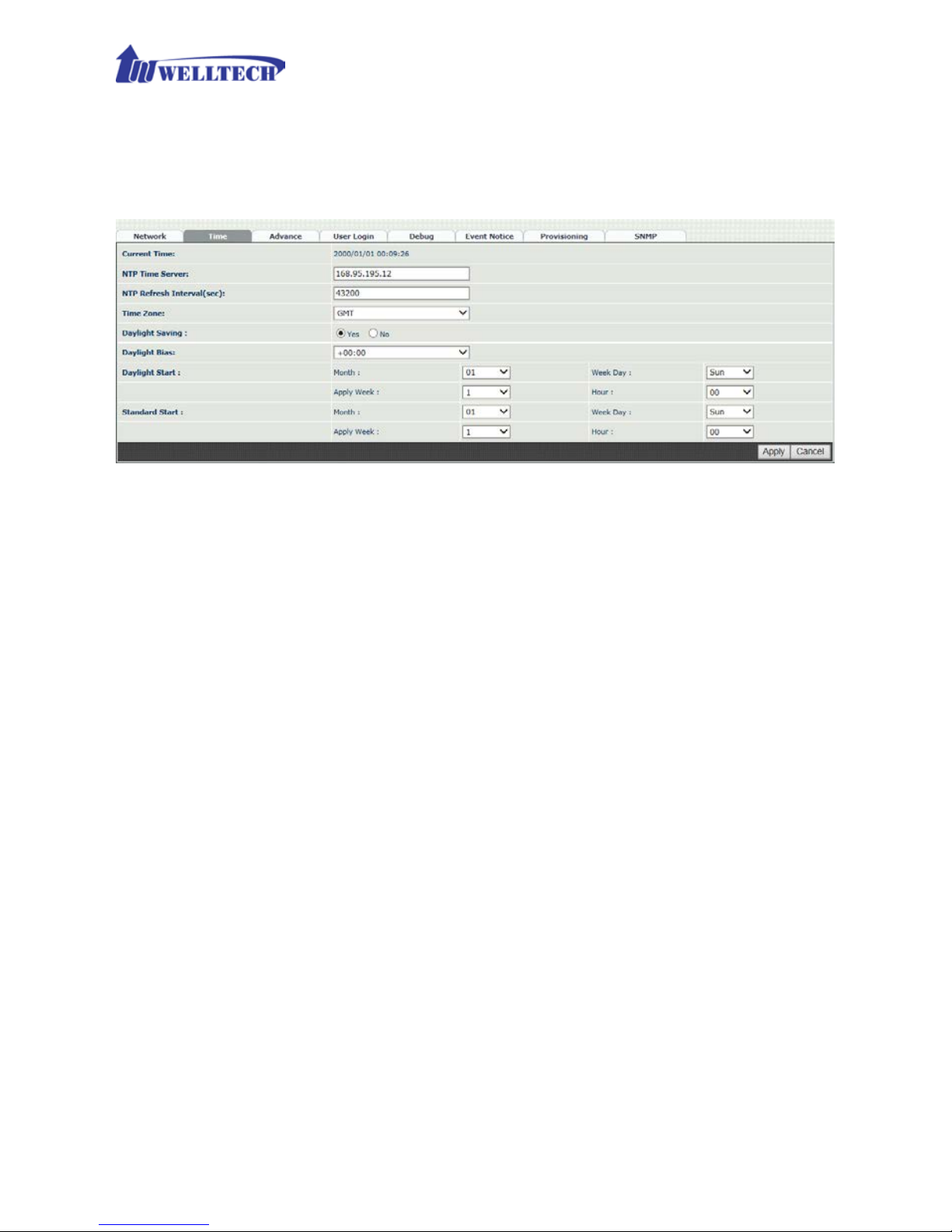
2-2 Device Time Setting
WellGate M4 supports NTP ti me server with time zone and daylight saving.
Device Setting --> Time
Figure 2-2 Time setting
Parameter Description:
Current Time: Show up current time and date.
NTP Time Server: To enter NTP time s er ver IP address.
NTP Refresh Interval(sec): The interval time to synchronize NTP
server time in seconds
.
Time Zone: The time-zone of WellGate M4 is located. It was indicated
base on GMT+xx:yy or GMT-xx:yy.
Daylight Saving: To enable daylight sa v ing timer automatic ally or not.
Daylight Bias: The offset added to the Bias when the time zone is in
daylight saving time.
Daylight Start: The date that a time z one enters daylight time.
- Month: 01 to 12
- Week Day: Sunday to Saturday
- Apply Week (Day:01 to 05, Specifies the occurrence of day in the
month; 01 = First occurrence of day, 02 = Second occurrence of
day, ...and 05 = Last occurrence of day)
- Hour: 00 to 23
Standard Start: The date that a time z one go back from dayligh t time.
- Month: 01 to 12
- Week Day: Sunday to Saturda y
Page 16

16
- Apply Week (Day:01 to 05, Specifies the occurrence of day in the
month; 01 = First occurrence of day, 02 = Second occurrence of
day, ...and 05 = Last occurrence of day)
- Hour: 00 to 23
Page 17
17
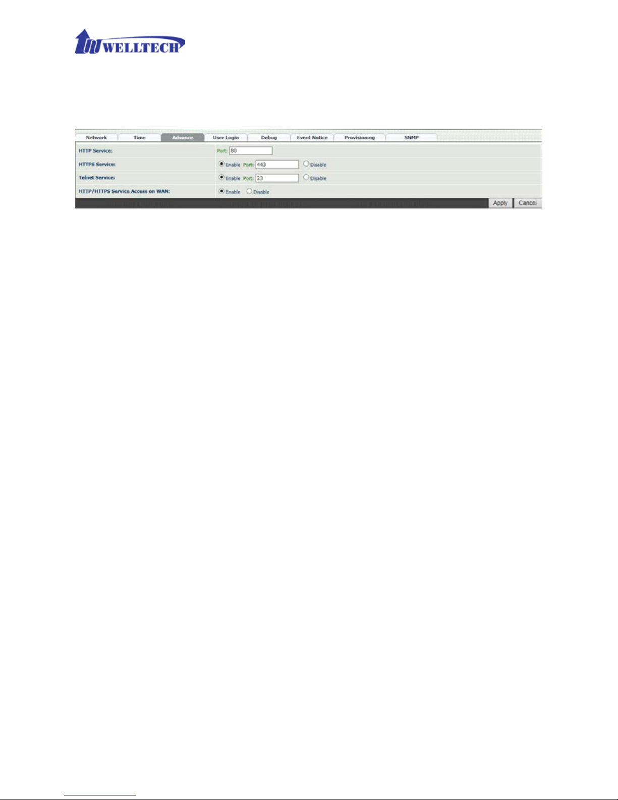
2-3 Device Advance Setting
--> Advance
Figure 2-3 Advance setting
Parameter Description:
HTTP Service: The HTTP Web service port (the default is 80).
HTTPS Service: The HTTPS web service port (the default is 443).
Telnet Service: The telnet service port (the default is 23).
HTTP/HTTPS Service access on WAN: When c lick the disable o ption,
the WEB access will be rejected on WA N port. So please be careful with
this function. If you wan ted to enable WAN por t again, you nee d to
access this device from its LAN port to connect to WEB pages and enable
WAN por t.
Page 18
18
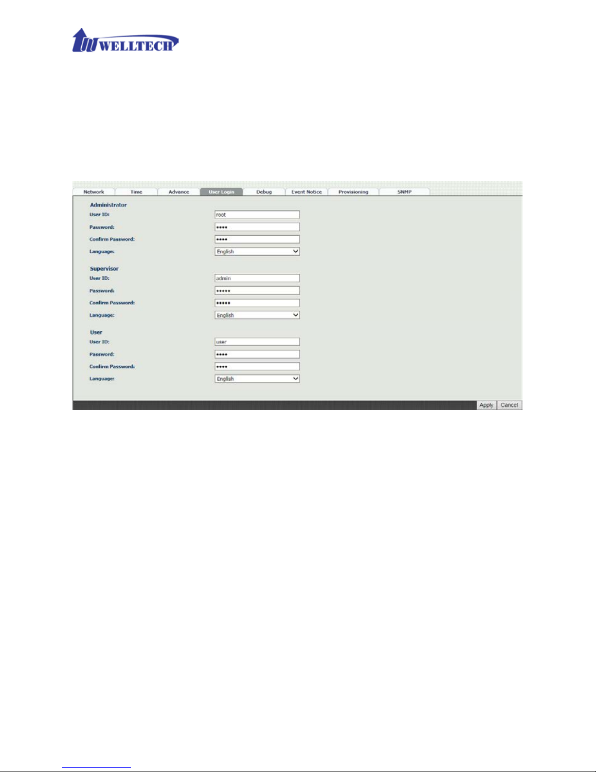
2-4 User Login Setting
Three levels of users login can be used. They are administrator, supervisor,
and user. Each level of users has different predefined access lev el.
-->User Login
Figure 2-4 user login setting
Parameter Description:
Administrator: The administrator level user which has full access of
WellGate M4.
Supervisor: The supervisor level user which has limited administrative
access right.
User: The user access right w hich only allows to setting some user
related features.
User ID: Login User ID.
Password: Login Password.
Confirm Password: Confirm new password again.
Language: The web page langu age used when the account login. To add
a customized local language, please contact Welltech.
Page 19
19
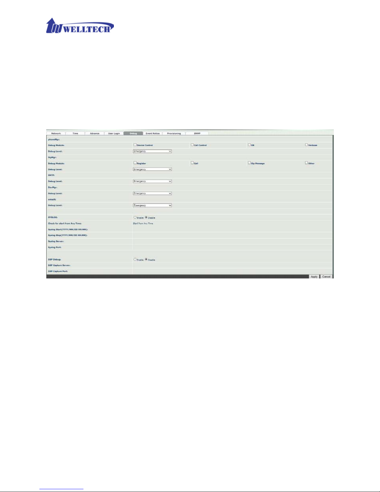
2-5 Debug Settings
WellGate M4 provides the real time debug to syslog or through telnet interface. It
generates the debug information based on debug level and modules. Since the
generating debug consumes system resources, it is recommended to turn on only for
debug period and under Wellt ech FAE’s instructions.
Debug
Figure 2-5 Debug setting
Parameter Description:
SYSLOG: Enable or disabl e to s en d sy stem in f orma tion to S YS L OG server
or not
Check for start from Any Time: Always send syslog at any time or on ly
during a specified date/time range.
Syslog Start (YYYY/M M/DD HH:MM): Send syslog at start Date and
time.
Syslog Stop (YYYY/MM/DD HH:MM): The syslog stop sending at
Date and time.
Syslog Server: Syslog server IP a ddr es s .
Syslog Port: Syslog server service port (default is 514).
Page 20

20
DSP Debug: Enable or disable to send DSP inform a tion to capture log.
DSP Capture server: Syslog capture server I P a ddr es s.
DSP Capture port: Syslog capture server service port (def a ult is 50000)
2-6 Event Notice
WellGate M4 can send Sy slog Event Notice when it has the following cases:
1. Register Failure or re-registered.
2. SIM card is ready or not.
3. Ethernet reconnected.
4. System started.
Figure 2-6 Event notice setting
Syslog Notice: Enable or disable to send s ystem event to SYSLOG
server or not
Syslog Server: Syslog server IP address
Syslog Port: syslog server service port (default is 5 14)
Page 21

21
2-7 Auto Provision
-->Provision
WellGate M4 offer configuration interface and allow manager to establish a
HT TP auto pro vision ser ver to conf igure this gatewa y automatic ally. Once you
enable and sele ct HTTP, th e following fields are relate d to HTTP s erver security
parameters.
Figure 2-7-1 Provision
Figure 2-7-2 Provision type of HTTP Server
HTTP config URL: This field is to configure HTTP Server IP address
and its path to s tor e configuration parameters files.
Refresh interval (minute): W e llG ate M4 will access HTTP
provision server to check if there are new configuration/firmware to
update according to this time inte r val in minutes.
User ID: Specify the Login ID for HTTP server authentication.
Password: Specify the password for HTTP server authentication.
Page 22

22
2-8 SNMP
WellGate M4 offers SNMP agent for cen tral sites to ma nage and provis ion.
Figure 2-8 SNMP
SNMP Agent:
SNMP Agent: Enable SNMP or not.
Read Only Community Name: The community name to read
through SNMP protocol
Read Write Community Name: The community name to read and
write through SNMP protocol.
SNMP Agent Access on WAN : Enable SNMP to access through
WAN port or not due to security r eason.
Trusted Peer:
Type:
Any Address: Any address can retrieve the SNMP
information.
Specify an I P Address: Only the designate IP address list
here can retrieve the SNMP information. Normally, it will be
the SNMP manger I P address.
Specify a Su bnet: Only the subnet network specified here
can retrieve the SNMP information.
IP address: The IP address for a trusted peer when you have
specified IP address.
Page 23

23
Subnet Mask: The network mask for a trusted peer when you
specify an Subnet.
SNMP Trap:
SNMP Trap: Enable SNMP trap or not
Destination: The IP address for SN MP manager to receive the SNM P
trap
Community: The community name for s ending the SNMP trap
Page 24

24
CH3 NAT Setting
WellGate M4 can support NAT, 2 Ethernet ports (WAN and LAN) or Bridge
mode. Here are the settings for NAT related services.
3-1 DHCP Ser. (DHCP server)
Figure 3-1 DHCP s erver
DHCP Server: Enable DHCP server or not at LAN port.
Client Range Start IP: specify DHCP client lease start IP
Client Range End IP: specify DHCP client lease end IP
Default Gateway: specify the defau lt gateway which is WellGate
M4 IP address at LA N port.
Submask: specify the subnet mask.
DNS Server 1: specify the DNS server IP address.
DNS Server 2: specify the DNS server IP address.
Page 25

25
3-2 UPnP (universal plug and play server)
Figure 3-2 UPnP
To enable UPnP server or not.
3-3 Bandwidth (Bandwidth Control )
By using bandwidth control feature, the user can manage the data traffic
based on their needs.
Figure 3-3-1 Bandwidth control
Bandwidth Control:
Bandwidth Control: enable bandwidth control or n ot.
Download Bandwidth: specify total bandwidth for download (unit:
kbps). 0 indicates no limitation.
Upload Bandwidth: specify total bandwidth for upload (unit: kbps).
0 indicates no limitation.
Maximum Bandw idth a nd Reserved Bandwidth:
Setup Method: bandwidth control method, percentage or specify
the required bandwidth
Percentage: define perc entage of total bandwidth to be used.
priority 1: highest priority percentage
priority 2: Normal priority per c e ntage
priority 3: low priority percentage
Page 26

26
Figure 3-3-2 Bandwidth control
Specific: define maximum and Reserved ba ndwidth in Kbps for
download and upload.
priority 1 – Download: highest priority download bandwidth
priority 2 – Download: normal priority d ownload bandwidth
priority 3 – Download: low priority download bandwidth
priority 1 – Upload: highest priority upload bandwidth
priority 2 – Upload: normal priority upload bandwidth
priority 3 – Upload: low priority upload bandwidth
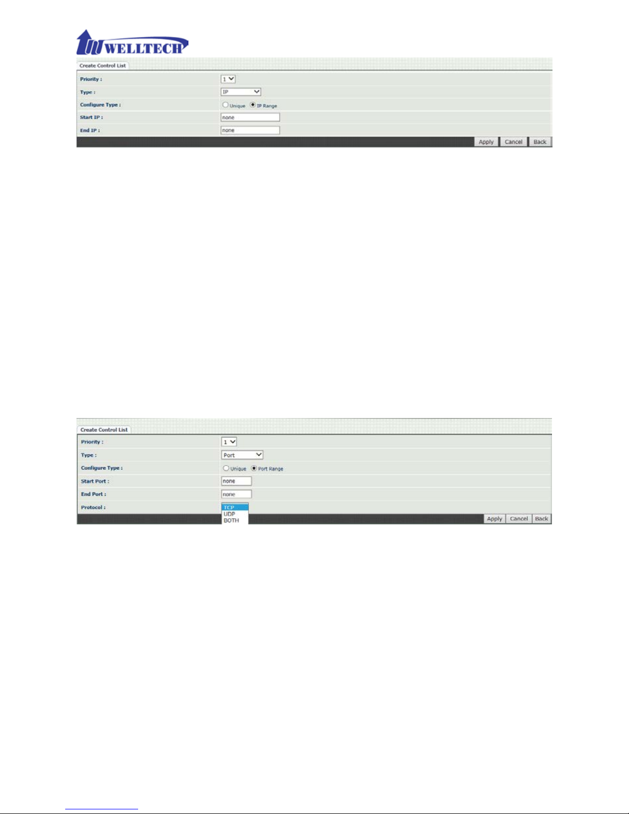
Edit Control List:
In order to set up w hich target is belonged to which priority, the following is
the setting me thod for target’s priority.
Figure 3-3-3 Edit control list
IP Target
Figure 3-3-4 IP Target 1
Page 27
27
Figure 3-3-5 IP Target 2
Priority: Priority value for the target
Type: The target type was set up to IP
Configure Type: unique IP or a range of IP address
Unique:
IP Address: the IP address to be set
IP Range:
Start IP: The starting IP for a range
End IP: The stopping IP for a range
Port Target
Figure 3-3-6 Port Target
Priority: Priority value for the target
Type: The target type is set to port number
Configure Type: unique port number or a range of port number
Unique:
Port: the port number to be added
Protocol: protocol for the port
Port Range:
Start port: the starting port number
End port: the stop port number
Protocol: protocol for the port r a nge
Page 28

28
A pp lic a tion Target
Figure 3-3-7 Application Target
Priority: Priority value for the target
Type: Application
Application: the lis t for the application
DS CP target
Figure 3-3-8 DSCP Target
Priority: Priority value for the target
Type: DSCP value
DSCP: The DSCP will be mapped to the priority
Page 29
29
WellGate M4 supports firewall features as follows.
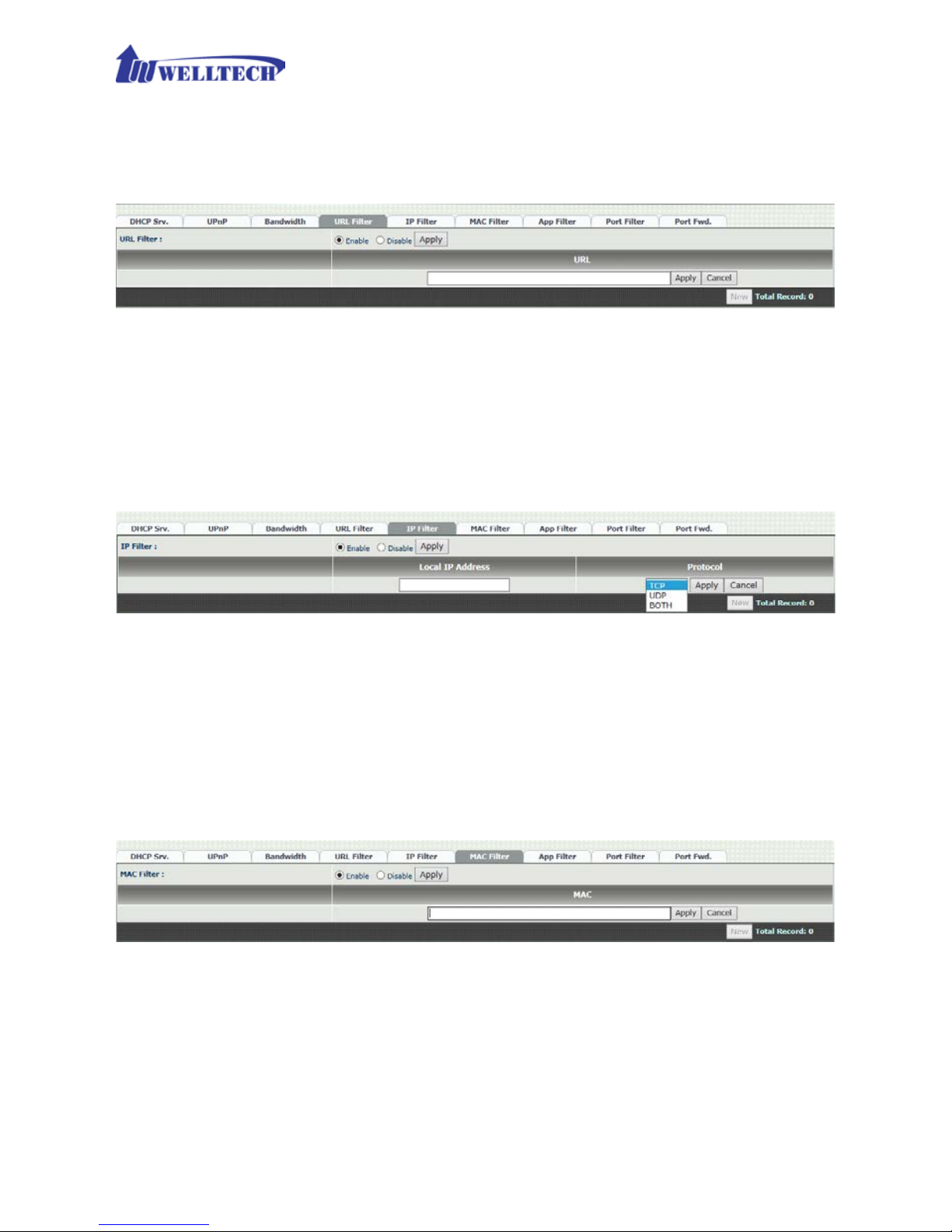
3-4 URL Filter
Figure 3-4 URL Filter
URL Filter: the specif ied URL will be blocked.
3-5 IP Filter
Figure 3-5 IP Filter
IP Filter: The specif ied IP address to be blocked.
Local IP addre ss: The LAN side IP address to be forwarded.
Protocol: TCP, UDP or both are used for port forward.
3-6 MAC Filter
Figure 3-6 MAC Filter
MAC Filter: The MAC address to be blocked.
Page 30
30
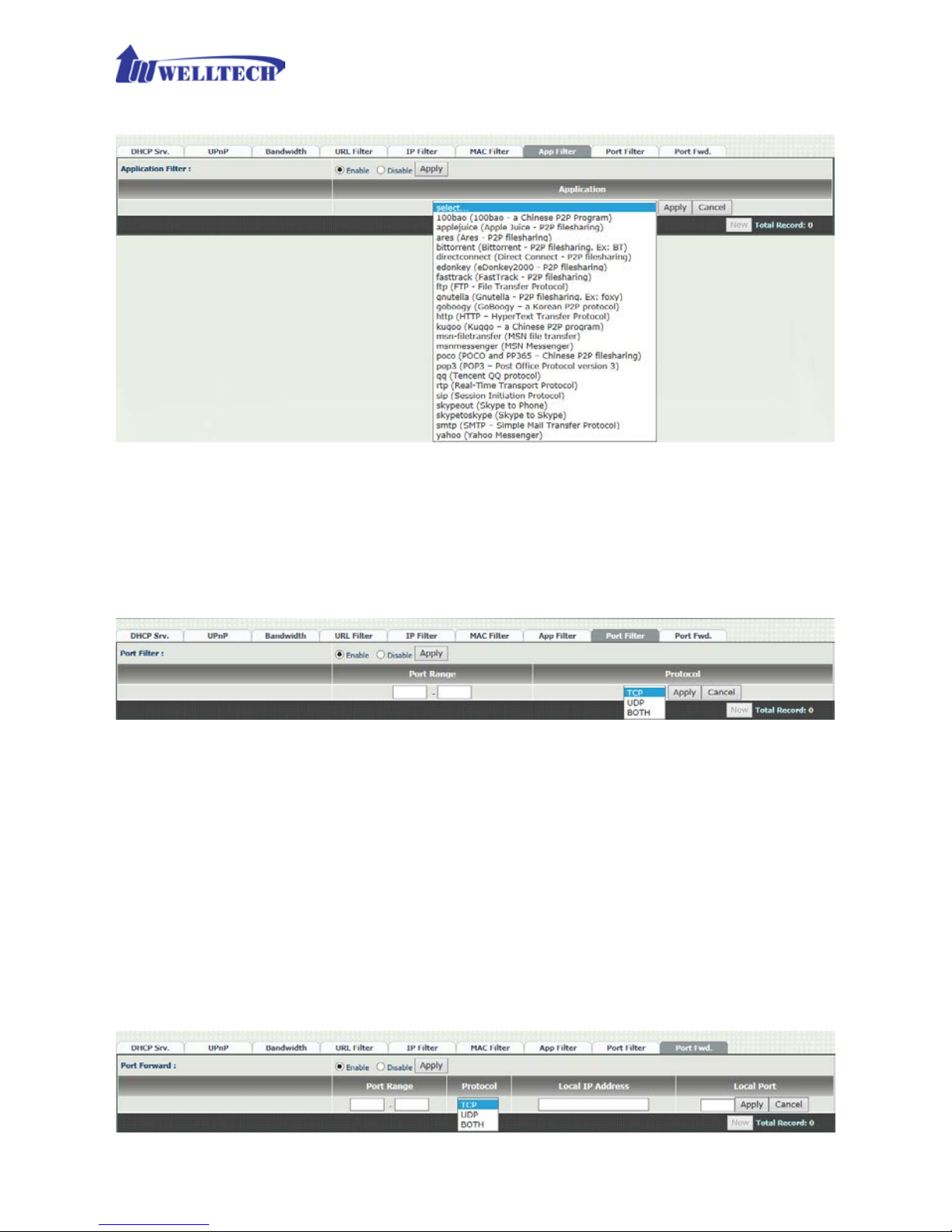
3-7 APP Filter
Figure 3-7 App Filter
APP Filter: The application to b e b loc ked.
3-8 Port Filter
Figure 3-8 Port Filter
Port Filter: enable port Filter or not.
Port Range: Startin g and stopping por t to be forwarded. If you are
using only 1 port, please s et up the starting equal to stopping
port.
Protocol: TCP, UDP or both are used for port blocked.
3-9 Port Fwd
WellGate M4 supports port forward f eature as follows.
Figure 3-9 Port Fwd
Page 31

31
Port Fwd: enable port forward featur e or not.
Port Range: Starting and stoppin g port to be forwarded. If you are
using only 1 port, please s et up the starting equal to stopping port.
Protocol: TCP, UDP or both are used for port forward.
Local IP addre ss: The LAN side IP address to be forwarded.
Local Port: The LAN side port to be forw arded. I f you are usin g the
port range, this port indicates the starting port.
Page 32

32
CH4 VOIP Setting
4-1 SIP
Figure 4-1 SIP setting
Parameter Description:
Session Ti m er: Enable session tim er or not (RFC 4028).
Session Expires (sec): This is the setting of initial session tim e r
expires time according to RFC4028 - Session Time r s in the Session
Initiation Protocol.
Min SE (sec): The minimum session timer allowed wh en receiving a
call with sess ion timer value according to RFC 4028.
PRACK: Enable provision ACK or not (RFC 3262)
- None: Disable PRACK
- Supported: When select thi s mode, the SIP command 100rel will be
added to the support list to send to remote side. It indicates
WellGate M4 can support the PRACK but not mandatory.
- Require: PR ACK is mandatory required.
SIP Local Port: The SIP local service port (default is 8080)
SIP QoS Type: Quality of Ser vice Type for SIP signaling
- None: Not using QOS Tag and not enables QOS.
- DiffServ: Differentiated Services Value. Input DSCP value 0-63 for
DSCP.
- TOS: Type of Service which include IP precedence value and TOS.
Accept Proxy Only: If you select YES, on ly ac cept th e c all com ing
from the registered SIP proxy. WellGate M4 Do Not accept peer t o
peer call at th is mode, neither acc ept from different SIP pro xy. This
configuration prevent from hacker atta cking.
P2P call applica tion: When you select NO at this option, this GSM
Page 33

33
gateway c a n be configured to Peer to Peer mode. For P2P call, y ou
also need to con figure Ph one book in ord er to dial re mote site phon e
number to send IP addres s dir ec tly. Please refer to Chapter 6-4:
Phone Book c onfiguration.
4-2 Audio
Figure 4-2 Audio setting
Codec 1~5: The preferred codec priori ty while a call was established.
The Codec 1 has the highest priority. While making a call, both
termination de vices will negotiate the priority Codec to be used to
establish voice connection .
The Voice Code Payload Size was indicated by time length . The talking
voice was sent to SIP IP networ k according to you r selected payload siz e
(ms) and pack header/checksum in order to transmit over Ethernet IP
network. The longer payload s ize time of voice codec w as used, the less
Ethernet IP bandwidth to consume. However, th e s ide effect is the
longer voice delay time at receiver side.
In application , if the IP network has limited IP bandwidth, y ou had better
to configure longer v oice codec p ayload s ize (time ) in order to reduce I P
bandwidth. For instance, if you are going to talk via VSAT which has
longer delay time, to s elec t G. 723.1 at 6.3kbps with 90m s pa yload s iz e
is the suitable one to provide a c c e ptable voice qua lity.
Page 34

34
G.711u Payload Siz e : G.711 u-Law payload size: 20ms and 40ms.
G.711a Payload Size: G.711 A-law payloa d s ize: 20ms and 40ms.
G.729 Payload Size: G.729A payload siz e: 20ms, 40ms, an d 60ms.
GSMFR Payload Size: GSMFR payload s ize: 20ms, 40ms, and 60ms.
G.723.1 Payload Size: G.723.1 payload size: 30ms, 60ms, and
90ms.
Bit Rate: G.723.1 bit rate used
5.3K bit rate is used
6.3K bit rate is used
Codec Priority : Selection order to match the r emote SDP for codec
selection.
Local SDP Order: Use local SDP order to match codec.
Remote SDP Order: Use Remote SDP order to match codec.
DTMF Relay:
In-Band DTMF: use In-band DTMF instead of out-band.
RFC 2833(fall back to SIP-INFO): Use RFC 2833 if the SDP
negotiation c ould be done. Or use SIP INFO for DTMF relay.
SIP INFO: Use SIP-INFO DTMF relay.
RFC 2833(fall back to Inban d): Use RFC 2833 if the SDP
negotiation could be done. Or use inband DT MF transmission .
Silence Suppression:
Enable: Start the voice activi ty ( silen ce) detec tion an d s end SID
when detecting silence.
Disable: Send silence packet as normal voice packet (no silence
detection)
RTP Basic Port: The RTP starting port. Each ch annel will be added
additional 10. For example, the RTP basic port is 16384, therefore,
call 1 will use 16384 wh ile ca ll 2 w ill u s e 16394 and etc.
RTP QoS Type: IP QoS tag for RTP stream
DiffServ: The differentiated service QoS ta g will be used.
Input DSCP value 0-63 for DSCP.
TOS: Type of Service wh ich include IP precedence va lu e a nd TOS.
Page 35

35
4-3 NAT Traversal
WellGate M4 supports the following NAT traversal methods when it was
installed beh ind private IP address.
Figure 4-3 NAT Traversal
NA T Traversal:
Disable: Disable NAT traversal features.
STUN (Type 1,2): Enable STUN for NAT tr aversal. Since
STUN can be used only f or type 1 and type 2 NA T serv er, it is
recommended to use th is option. When STUN client detect
the used NAT is type 3 NA T, it will stop the STUN feature.
STUN Server: STUN Server IP address
STUN (All): No matter which NAT type server are used,
STUN is always to be used for NAT traversal.
STUN Server: STUN Server IP address
UPNP: Enable UPn P client for NA T trav ersal. Please note tha t
the IP sharing box need support UPnP feature.
Behind NAT: Use DMZ for NAT traversal.
IP Sharing Address: public IP sharing address. You
need to specify the port mapp ing or DMZ for all
required port.
Page 36

36
CH5 VOIP Advance
5-1 SIP
Figure 5-1 SIP
Parameter Description:
SIP Hold Type: SIP up on hold message sending method.
- Send Only: Set the SDP media to send only when send an on-hold
SIP message.
- 0.0.0.0: Set up the SDP connection to 0.0.0.0 when send an on-hold
SIP message.
- Inactive: Set up the SDP media to inactive when send an on-hold
SIP message.
SIP Compact Form: Enable SIP c ompact form or not. When en able
this featur e, the connected SIP proxy is requ ired to support compac t
form.
Session Refresher: Who will send dialog keep alive message
(re-invite or upd a te).
- UAC: User Agent Client will do th e r e fresh (defau lt setting)
- UAS: User Agent Server will do the refresh.
SIP T1 (msec): T1 determines several timers as defined in
RFC3261. For exa m ple , when an unreliable transport protocol is
used, a Client Invite transaction retra nsmits requests at an interval
that start at T1 seconds and doubles after every retransmission. A
Client General transac tion retransmits requests at a n interval tha t
starts at T1 and doubles until it reaches T2. (Default Value: 500ms)
SIP T2 (msec): Determines the maximum retransmission inte r val
Page 37

37
as defined in RFC3261. For example, when an unreliable transport
protocol is used, general requests are retr a nsmitted at an interval
which sta r ts at T1 and doubles until reac hes T2. If a prov is ional
response is rec eived, retra nsmission continu e but at an interv al of T2.
(Default Value: 4000ms)
SIP T4 (msec): T4 represen ts the amount of time th e network
takes to clear message between client and server transactions as
defined in RFC3261. For example, when workin g with an unreliable
transport p rotocol, T4 determines the time th a t U AS waits for after
receiving an AC K m es s a ge an d bef or e term inating the transa c tion .
(Default Value: 5000)
Invite Linger Timer: After sendin g an ACK for an INVITE final
response, a client cannot be sure that the server has received the
ACK message. Th e client should be able t o retransmit the ACK upon
receiving retr a nsmissions of the final response for this timer. This
timer is also u sed when a 2xx respon se is sent for an incomin g Invite.
In this case, the ACK is not part of th e Invite transaction .
General Linger Timer : After a UAS sends a final response, the UAS
cannot be sure tha t th e c lien t has received the response m es s a ge.
The UAS should be able to retrans m it the response upon receiv in g
retransmiss ions of the requ est based on this timer.
Cancel Gene r a l No Response Time (msec): When sending a
CANCEL request on a General transaction, the User Agent waits for
cancel General No Response Timer milliseconds b efore timeou t
termination if there is no respon s e for the cancelled transaction.
(Default Value: 10000ms).
General Request Timeout Timer (msec): After s ending a
General reques t, th e U s er A gent waits for a final respon s e general
Request Timeout Timer milliseconds befor e timeout termina tion (in
this time the User Agent retransmits the request every T1,
2*T1,…T2,…milliseconds).
Cancel Invite No Response Timer (msec): When sending a
CANCEL request on an Invite request, the User Agent waits for this
timer before timeout termin a tion if there is no r esponse for the
cancelled transaction.
Provisional Timer (msec): The provisionalTimer is set when
receiving a pr ovisional response on an INVIT E transaction. The
transaction will stop retransm is sions of the INVITE request and will
wait for a final response un til the provisionTimer expires. If you set
up the provisionTimer to 0, no timer is set. The INVITE transaction
Page 38

38
will wait for indefinitely for the final response.
First Response Timer (msec): When sending a request out, the
User Agent waits for this timer for any r esponse receiv ed from UAS .
If timer is expired and not any SIP message is rec eived, the User
Agent will think the request is f a ile d. The default is 5 s e c onds.
Line Congestion Code: When callee's end system was contacted
successfully but the callee is busy and does n ot wish to take th e cal l
at this time, the system wills response the code, default is 600.
Page 39

39
5-2 Audio
The setting page in c ludes the device related audio settings.
Figure 5-2 Audio setting
RFC 2833 Payload Type: 96 or 101. It is rec ommended to us e 101.
DTMF Send On Time(msec): When genera te DTMF, the DTMF on
time will be sen t ( d efault time is 70 ms)
DTMF Send Off Time(msec): When gener ate DTMF, the D TM F OFF
time between two digits will be sen t (default time is 70 ms)
DTMF Detect Min on Time (msec): The minimum DTMF ON time
will be recognized as a regular DTMF event. Less than this time will be
ignored. The default value is 60ms.
DTMF Detect Min off Time (msec): The minimum DTMF OFF time
between two di gits to recognize. Less than this tim e , the next DTMF
digit will be recognized as the same previous one. It will be handled as
one digit only instea d of two digits.
DTMF Relay Volume: The DTMF relay volume in dBm.
Min Jitter Buffer (msec): The minimum dela y time of Jitte r bu ff er.
Max Jitter Buffer (msec): The Maximu m delay time of Jitt er buffer.
Max Echo Tail Length (G.168): Enable the echo cancellation
feature. The default settin g is 128ms.
Jitter Opt. Factor: Jitter buffer d ynamic factor for optimize. Please
set to 7 unless under Welltech’s instru ction to change.
Page 40

40
CH6 Dialing Plan
6-1 General
Figure 6-1 General setting
First Digit Time Out: Specify the maximum waiting time to dial th e
first digit onc e you hear dial tone. The range is 1~60 sec.
Inter Digit Time Out: Specify the in terval time to wait for the next
digit to enter before sending out. If the inter val is over the setting
time, the sys tem will end the dial and send out the DTMF. The
limitation
range is 1~10sec.
End of Digit: The assigned k ey will be treated as end of dial. The
factory def a ult key is “#”.
Retrieve Number: Th is feature is not applied to G SM gateway.
Page 41

41
6-2 Dialing Rule
Figure 6-2 Dialing Rule setting
Dialing rule is used to speed up the dialing procedure while you hav e dia led
complete dig its. Some users don’t like to use the en d of dialing digi t such as #
key, this GSM gateway can be configured to use dialing rule in stead. The
longest digits of prefix code will be selected first if it was matched.
Dialed Prefix: The prefix code to be matched.
Max Digits: The digits will be received bas ed on the Dialed Prefix
code and the following number.
The followin g is an example for dialing rule:
Mobile call start with prefix: 09, and it is 10 dig its length.
Long distance call start with prefix: 0, and it is 10 digits length.
Internation al call start with prefix: 00, and its max digit shou ld be less than
32 digits.
The others are local call (city call) with 8 digits maximum length.
Emergency call start with prefix: 1 and 3 digits, and its maximum digit is 3
digits length.
The Dialing Rule setting can be configured as follows:
Dial Prefix number
Maximum digit le ngth
Remarks
09
10
Mobile call
0
10
Long distance call
00
15
International Call
1
3
Emergency Call
9
3
Emergency Call
2
8
City Call
3
8
City Call
4
8
City Call
5
8
City Call
6
8
City Call
7
8
City Call
8
8
City Call
Page 42
42
9
8
City Call
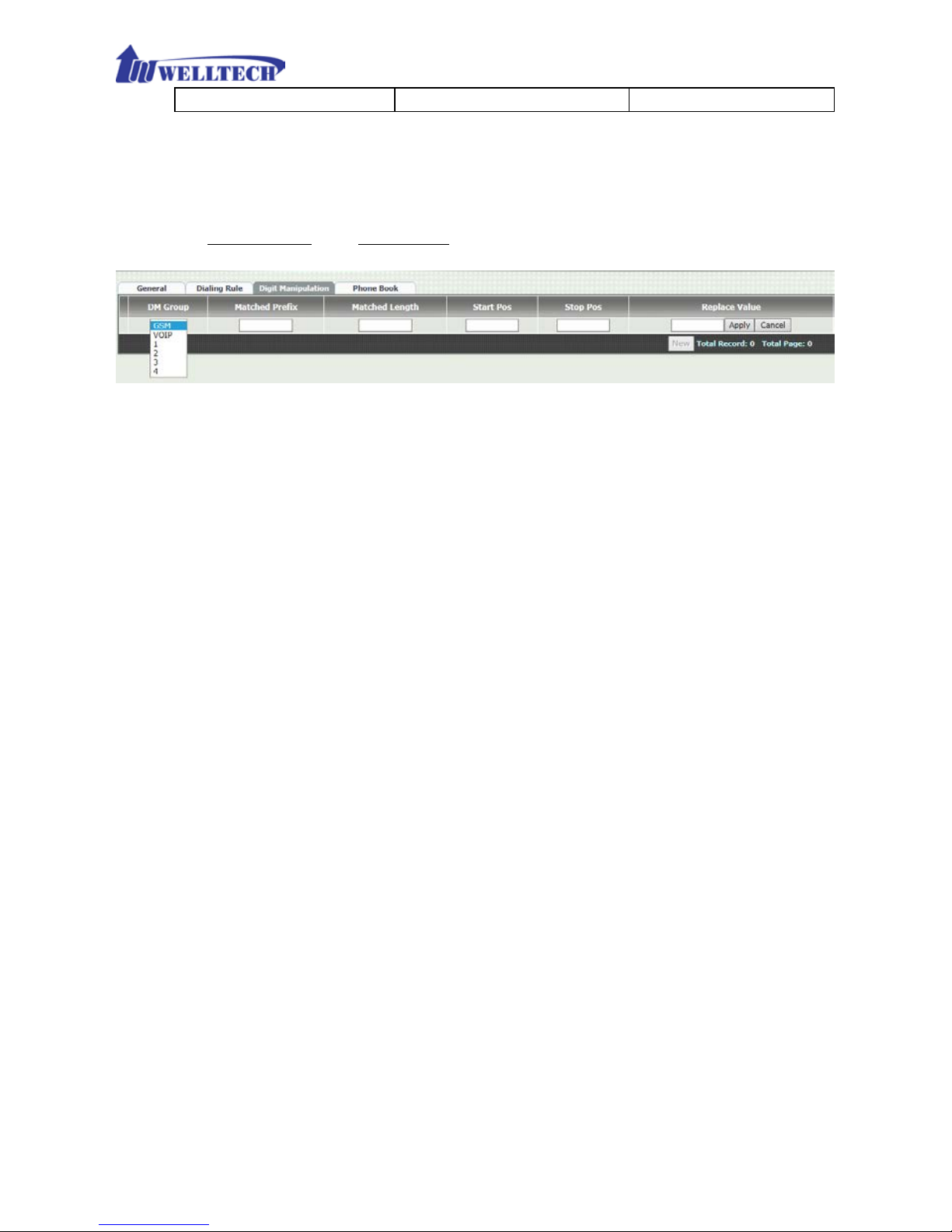
6-3 Digit Manipulation (DM)
The Digit Man ipulation is to define outgoing call rule and will be processed
based on prefix code and DM group after the DNIS is determined.
Figure 6-3 Digit Manipulatio n setting
DM Group: Different DM group have dif ferent dial plan to be used.
There are six DM gr ou ps to be conf igured.
GSM: This DM group describes GSM incomin g cal l and w ill rou te
to next receiver. It is used for GSM 2 stage dialin g only. After the
DNIS is collected (dialing number), this DM group will be
processed before entering the dia l out routing proced ure to V oIP
SIP Trunk.
VOIP: T his DM group is u sed for VOIP incoming call and route to
GSM outgoing call. After the DNIS (the name dial to GSM line)
was collected in 1 stage dialing DNIS, this DM group will be
processed before entering the routing procedure.
1-4: These DM groups are used for backup routing purpose.
When a backup routing is used, the administrator can select a
DM group to be processed before starting the backup outgoing
route call.
Matched Prefix: The prefix to be matched for DM. The longest prefix
digits will be se le c ted first to chec k if it is matched.
Matched Lengt h: Set to 0 for ignoring the length. The other 1-32
digits length are the length to be matched as a condition.
Start Pos: The next digit of start digit position to be replaced.
Stop Pos: The stop digit position to be replaced.
Replace Value: First, the next digit position of start digit position
until stop digit position will be removed. Then replaces with the
Replace Value.
Page 43
43
Example of Digit Manipulation Settings:
Prefix
Length
Start
Pos
Stop
Pos
Replace
Value
Before DNIS
Result DNIS
886
0 0 0
002
8862123456
0028862123456
886
12 0 0
002
8862123456
8862123456
886
0 2 5
002
8862123456
8800223456
886
0
30
30
002
8862123456
8862123456002
886
0 1 6 8862123456
83456
Note: The DM Group 1~4 has the feature to pause the dialing by adding a p
to replace digit value for a pause dialing. It is useful if you want to wait for
several sec onds during dialing. Each p represents one seconds pause. For
example, to dial these digit: 822265699ppp1234; these num bers 82265699
dial first and pause 3 seconds to dial remaining digits, 1234.
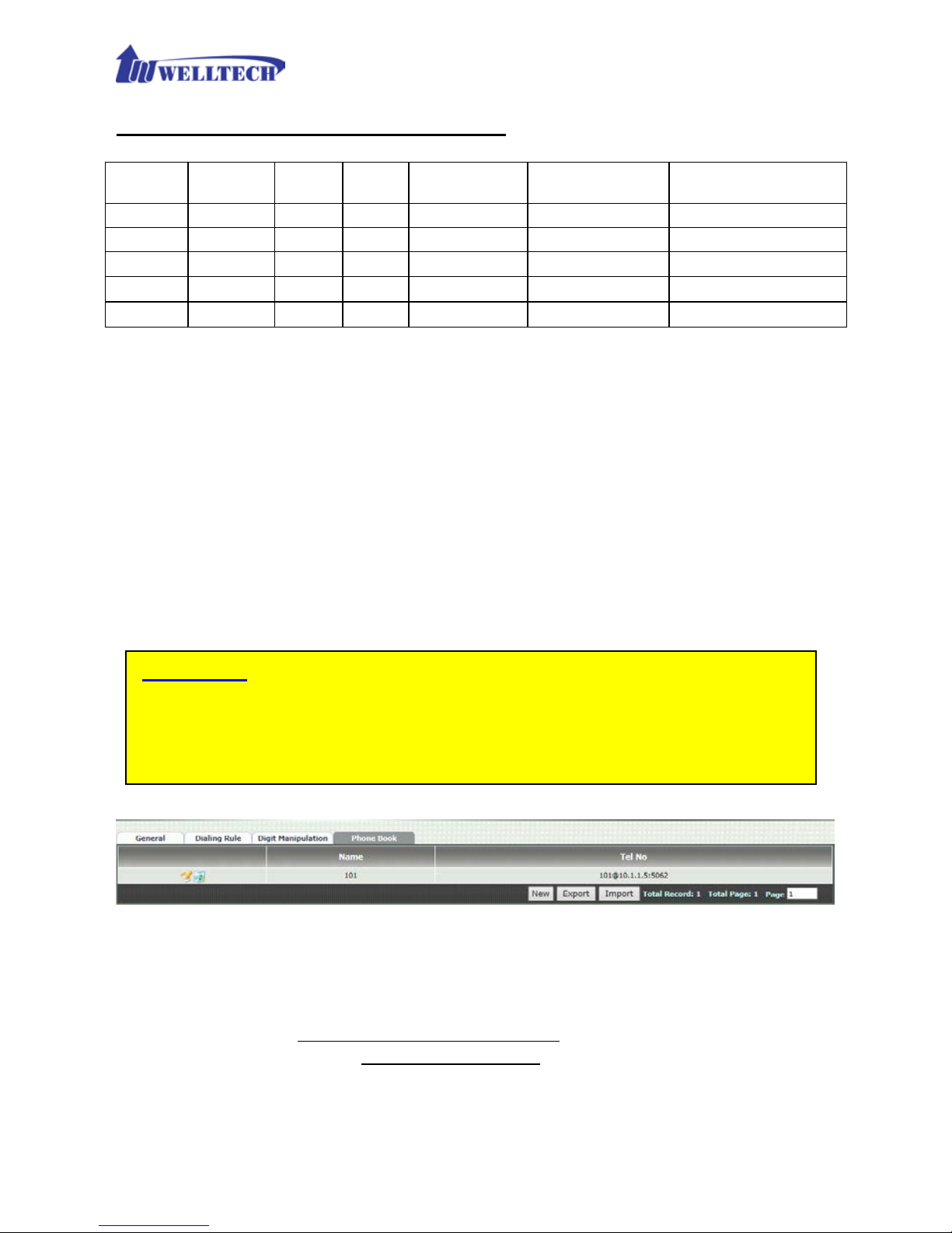
6-4 Phone Book
Phone Book is used to send ou t SIP IP peer to peer c all from WellGate M 4. The
limitation of maximum phone book is 100 r ec ords .
Figure 6-4 Phone Book setting
Name: This field supports called number only. If you enter words or
text here, it will routes to proxy server automatically.
Tel No: Enter called number @ IP address. Please refer to above Figure
6-4, at the format of number@uri:port. (default port is 5060 if you
don’t enter port number.)
Export: To back up the phone book records to y our com puter h ard disk .
Attention:
When WellGa te M4 wa s configu red to P2P call, th e SIP I P incom ing call
to GSM outgoing call only s upports one sta ge dialing . It means that the
SIP IP incoming call should car r y GSM destination number (PSTN
number).
Page 44

44
Import: To reload setting of phone book from your computer ha rd dis k.
Page 45
45
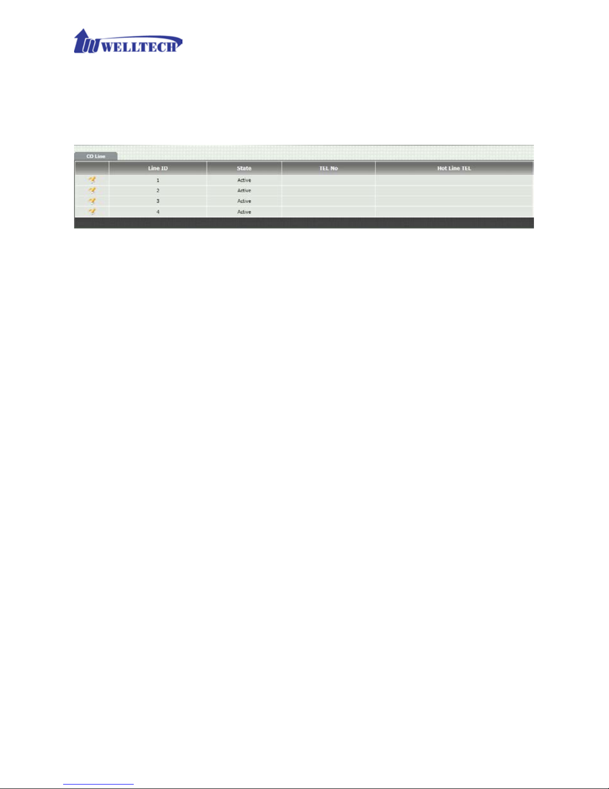
CH7 CO Setting
The CO Line setting contains the GSM related parameters.
Figure 7-0 CO setting
Line ID: There are four GSM lines. Line ID indicates one of them (L1
to L4).
State: The GSM line is activ e or inactive.
TEL No: The reference telephone nu m ber ( e.g. SIM Card number).
Hotline TEL:
This featu re is used f or GSM in coming call a nd route to
SIP IP Trunk with telephone number automatically. If hot line is
configured, this field shows the hot line number.
Page 46
46
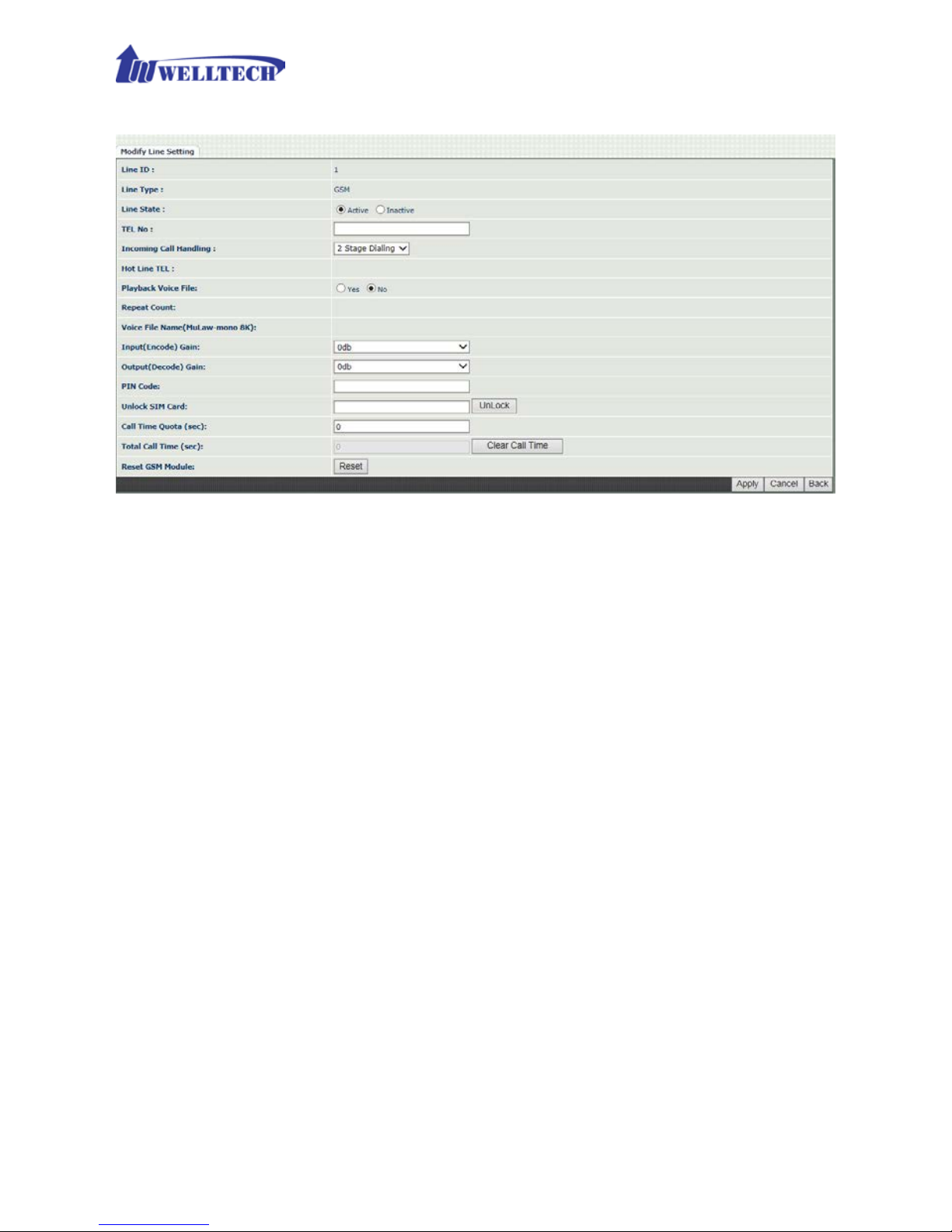
7-1 CO line
Figure 7-1 CO setting
Line ID: There are four GSM lines. Line ID indic ates one of th em (L1
to L4).
Line Type: The line type is GSM.
Line State: To activate if you would like to use this line. Otherwise,
inactive to disable this line.
TEL NO: This field can be used as a reference remark for this GSM
SIM number. Normally, you can put the connected SIM card number
here for referenc e.
Incoming call handling: The call handles policy for a GSM
incoming call.
Hot line TEL: When a GSM incoming call was detected, GSM
Gateway will send the SIP call to the specified hot line TEL
number through the Route Plan.
2 Stage Diali ng: When GSM incoming call was detected, GSM
Gateway will answer it and play the dial ton e(if “Play Voice File”
command was not activated) for 2 stages dialing to VOIP.
Playback voice file: T o enable pla ying voice greet ing file to caller or
not when GSM incoming call was configured to 2 Stage Dialing.
Repeat Count : Repeat how many times to play voice greeting file
during 2 Stage Dialing.
Page 47

47
Voice file name (voice file format: Mu-Law, Mono, 8K): Specify
the file path a nd file name to upload in order t o play V oice greeting file
while there is GSM incoming call. Please make sure that your
recorded greeting file f orm a t n eeds to be G.711u/Law, Mono, 8K,
8 bits raw file.
Input(Encode)Gain: Adjust the volume fr om GSM to VOIP (def au lt
is 0 dB).
Output(Decode)Gain: Adjust the volume from VOIP to GSM
(default is 0 dB).
PIN Code: enter the PIN code to activate the SIM Card.
Unlock SIM Card: en ter the PUK code to activate the SIM card when
the SIM card was locked. The PUK code was given by your service
GSM opera tor company.
Call Time Quota (sec ): Y ou can define accu mulation max imum talk
time at each GS M lin e in order to restric t call ou t tim e in s econ ds via
GSM. If the total ta lk tim e was over this valu e, M 4 GSM gatew a y will
reject making call out from GS M port while there is in coming call from
IP side. (If the call time was over the limit seconds during talking
period, the call can continue. M4 GSM gateway will reject call out at
the next call attempt.)
Total Call Time (sec): T o show the accumulated talk time which had
been calling ou t from this GSM port up to now .
Clear Call Time: Reset/Clear the Total Call Time to zero.
Reset GSM Module: If the SIM card was plugged in to th at GSM line
while power is already ON at WellGate M4 gateway, Please click
Attention: How to record your own greeting f ile ?
WellGate M4 doesn’t provide an y tool for you to reco r d your own
greeting file. You ma y use computer with recor ding program an d install
external micr op hone to record.
If you have existing greeting file, you may need to use r ec ording
program to cov e r t to G.711u-Law, Mono, 8K and 8 bits file format.
The recorded greeting f ile time should not be more tha n 15 seconds.
Otherwise, the file size is too big to upload WellGate M4.
Page 48

48
“Reset” button to that GSM line in order to activate GSM module.
Page 49

49
CH8 SIP Trunk
SIP Trunk (the physic a l p or t is WAN RJ-45 connector) was used to make call
from GSM line to SIP IP network to r em ote device, or receive incoming c all
from remote de vice to W ellGate M4 via S IP IP Trunk.
W ellGate M4 needs to be set up the SIP trunk for VOIP outgoing c all from GSM
line and incoming call from SIP Trunk to GSM line. There are up to 4 SIP trunk
can be used for whole system.
Figure 8-0 shows f our SIP T runk major configur ation status. Y ou can click each
Trunk to enter details contents and modify your desire parameter s .
Figure 8-0 SIP Trunk page
Trunk ID: SIP trunk ID selection. There are 4 SIP Trunks can be
used.
Register Type: This feature is used to connect WellGate M4 with
other SIP devices or SIP Server. Register type has two modes:
Predefine or Register. Predefine is used t o connect to SI P Server or
IP-PBX directly, however, Register is registering to SIP Server or
IP-PBX as a Gateway.
TEL No: The Telephone Number for the SIP account.
Proxy Server: The SIP proxy server or IP-PBX IP address.
Proxy Server port: The SIP proxy server or IP-PBX port.
Outbound Proxy : The SIP outbound proxy server IP address.
Outbound Server Port: The SIP outbound pro xy server port.
Export: To back up or copy out these 4 SIP Tru nk configurations to
your com puter’s hard disk as SIP Trunk File.
Import: To reload setting of S I P Tr u n k from your computer stored
file.
Page 50

50
8-1 Create SIP Trunk
Figure 8-1 SIP Trunk page
Trunk ID: SIP trunk ID.
Register Type: W hether this account need register or n ot.
Register: When it was set up to reg ist er, WellGate M4 will send
REGISTER message to SIP proxy server (or IP-PBX server) for
registration.
Predefine: When it was set up to predefine, WellGate M4 DO
NOT sen d REGI STER message to SIP Proxy ser ver (or IP-PBX).
Domain: This field was used for Register Only (not for Predefine
mode). The Domain name of SIP proxy server can be entered IP
address to make call via SIP Trunk.
Proxy Server: SIP registrar server or IP -PBX server IP address for
WellGate M4 to regist er.
Proxy Server Port: SIP registrar server port nu m ber.
Outbound Proxy S erver: outbound proxy server IP address.
Outbound Proxy server port: outbound pro xy server port n umber.
Register Expires: the default register time expired du ring
registration negotiation.
TEL No: The registrar telephone number.
Page 51

51
User ID: The SIP user ID was used for registration and making a call.
User Password: The SIP password was used for registration and
making a call.
Display Name: The SIP display na m e.
Reject Anonymous Call: Reject the anonymous incoming call from
SIP Trunk.
Outgoing Call er ID: The outgoing call to SIP Trunk caller ID mode
contains two fields, Display Name and User ID.
- Dis play Name: The display name will be set up according to
the following type.
None: The display name doesn’t send in caller ID format.
PSTN caller ID: The PSTN caller ID from G SM line is used as
display name.
SIP display name: The “Display Name” field of SIP T run k will
be used as SIP d is p lay name for outgoing call.
GSM Tel NO: The GSM SIM car d phone num b er of incom ing
GSM line will be used as SIP display name for outgoing
call.
- User ID: The SIP caller ID will be used according to the
following type.
SIP user ID: If the SIP user ID is set, the SI P user ID set in
this SIP tr unk will be used and the dom ain/SIP pro xy will be
the host part. The SI P FROM header’s URL will be the
SIP_User_ID@Domain or SIP_User_ID@SIP_Proxy_Server.
PSTN caller ID: If the PSTN caller I D will be used in SIP UR L,
the SIP FROM header’s URL will be
PSTN_Caller_ID@local_IP_address.
GSM TEL NO: If the GSM SIM card Telephone number will be
used in SIP URL, the SIP FROM header’s URL will be
GSM_Tel_NO@local_IP_address.
Attention:
The followin g g uideline could be used f or the most application cases:
1. If the WellGate M4 was registered at SIP proxy or IP-PBX and was
configured as a gateway, Please enter “PSTN caller ID” at both
Display Name and Caller ID field.
2. If the WellGate M4 was registered at SIP proxy or IP-PBX and was
configured as a subscriber, Please enter “SIP User ID” at both
Display Name and Caller ID field
Page 52

52
Keep Alive: Enable or D isable it.
Keep Alive Time (sec): Specify of times in second to send SIP
register message to proxy server or IP-PBX.
For DNIS is R egistered TEL: This feature was used for SIP Trunk
incoming call a nd outgoin g to GSM lin e. The current firmware version
only provides 1 Stage Dialing selection. The 2 Stage Dialing isn’t
available at present.
Page 53

53
CH9 Route Plan
The core of WellGate M4 is the routing policy. The policy is based on
incoming call type/target, length and prefix to determinate the
outgoing call process. For VOIP incoming call, it can send to GSM
interface an d vice versa.
Figure 9-0 Route Plan page
Incoming Cal l Type: Incoming call type (GSM or VOIP)
Matched Prefix: matched DNIS incoming (called number) prefix
Matched Incoming List: matched DNIS incoming inte r face target
Matched Length: matched DNIS incoming digit (called number)
length.
Outgoing Type: The incoming call (GSM or VOIP) was routed to
outgoing call type (GSM or VOIP).
Page 54

54
9-1 Create Route Plan
Click Route Plan and Click new to create a ne w routing policy.
Figure 9-1 Route Plan setting
Incoming Cal l Type: Incoming call type
VOIP: The incoming call from SIP T r unk VoIP. It can only
route to GSM.
GSM: The incoming call from PS TN GSM type. It can only
route to VOIP SIP Trunk.
Matched Prefix: matched DNIS incoming (called number) prefix .
Matched Incoming List: matched DNIS incoming GSM Lines. This
command is n ot applied to VOIP SIP Trunk incoming call. Only the
GSM call is coming f rom the selected line (GSM Line 1 to Line 4) will
be accepted f or this route plan.
Matched Length: matched DNIS incom ing call digit ( called number)
length. To ignore the length, please set up to 0 (zero).
No Answer Timeout: How long the hunting will continue to next
incoming call when the called target doesn ’t answer.
Create Route Plan>Primary Route
Outgoing Type : Outgoing call type (GSM or VOIP)
Hunting Type: The hunt ing metho d (how to select one GSM line or
SIP Trunk) will be used for this route call.
Priority Ring: The outgoing call will be hunted based on
Page 55

55
the routing list order one by one (01 is the first priority
and 04 is the lowest priority).
Cyclic Ring: The outgoing call will be hunted based on
the cyclic basis from 01 to 04 and repeat. This is the
recommended method.
Routing List:
The outgoing routing target list (GSM Line 1 to 4, and
Trunk ID 1 to 4) will be used for this route call.
DM Group: Select DM (Digit Manipulation) group 1 to 4 in case it
requires DM to remove the prefix before makin g the outgoing call.
Create Route Plan>Backup Route
Backup Route Active: Activate the backup route or not.
Outgoing Type : The backup r oute outgoing call typ e.
Hunting Type: The hunting method will be used for this route.
Please refer to the P rimary Rou te .
Routing List: The backup routing target list will be used for this
route.
Reroute DM Group: Select DM group 1 to 4 in case the backup
required the DM before to make the call. The DNIS is unchanged by
the primary route DM and same as the DNIS before routing. For
example, the DNIS is 88628226 569 9 and pr imary DM group r emove
886 and use it (DNIS = 282265699) to make call. When backup route
is started, the DNIS is still unchanged as 88628226 5699. This makes
the DM easy to p r ed ic t a nd implement.
There are two special default routes, VOIP Default Route and GSM
default Route , are used as the default routing when there is not any
other routing are matched. It is not recommended to disable these 2
default route s. The GSM default route is used wh en a GSM incoming call’s
default routing. VOIP default route is used for a VOIP incoming call’s
default routing.
Page 56

56
CH10 Status
WellGate M4 shows out the current system status here.
Figure 10-0 Device Status
10-1 Device Status
See the figure 10-0 Device Status
Model: The model number, WellGate M4.
MAC-Address: The MAC address of WellGate M4
Network Type: The Network Interf a c e Type Settings
IP-Address: IP address is using
IPV6 IP-address: display IPV6 address
Firmware: The firmware version and release information
10-2 Line Stat es
This page shows each line’s current status.
Figure 10-2 Line Status
Line: L1 to L4 of GSM.
Call State: The Line sta tus for this GSM line, Not Connected, B usy or
Idle.
Not Connected Reason: SIM Busy (Not SIM card or invalid)
RSSI: This shows the Received Signal Strength Indicator of the
current GSM cell. The range is from 0 to 31 whic h represent a signal
level ranging from -113 dBm to -51 dBm. Each i ncrement in RSSI
values means 2 dBm increments. The 99 means that the sign al level
Page 57
57
is unknown or undetected.
IMEI: It indicates International Mobile Station Equipment Identity.
Which is a number, usually unique to identify 3GPP (i.e., GSM, UMTS
and LTE) and iDEN mobile phones, as well as some satellite phones.
IMSI: It shows Internationa l Mobile Subscriber Iden tity which is used
to identify th e user of a cellular netw ork and is a unique id entificati on
associated w ith all c ellular netw orks . It is stored as a 64 bit field and
is sent by the p hone to the network .
Remain: display the remaining time if the Call Time Quota was
configured. Once the Total Call time (accumulated call time) equal to
Call time Quota (Remaining time reaches zero), the corresponding
GSM line is locked a nd stop dial dig it to PSTN network at the nex t call
attempt.
10-3 SIP Trunk Status
Figure 10-3 SIP Trunk Status
Account: SIP trunk account number.
Registered: Th e SIP trunk register status.
Concurrent Call: How many concurrent calls are using th is SIP trunk
now.
Refresh Interval (sec ond): The interval time to refre sh the statu s.
Page 58
58
CH11 Maintenance
WellGate M4 can be managed by this managem ent page for upgrading
firmware or reset.
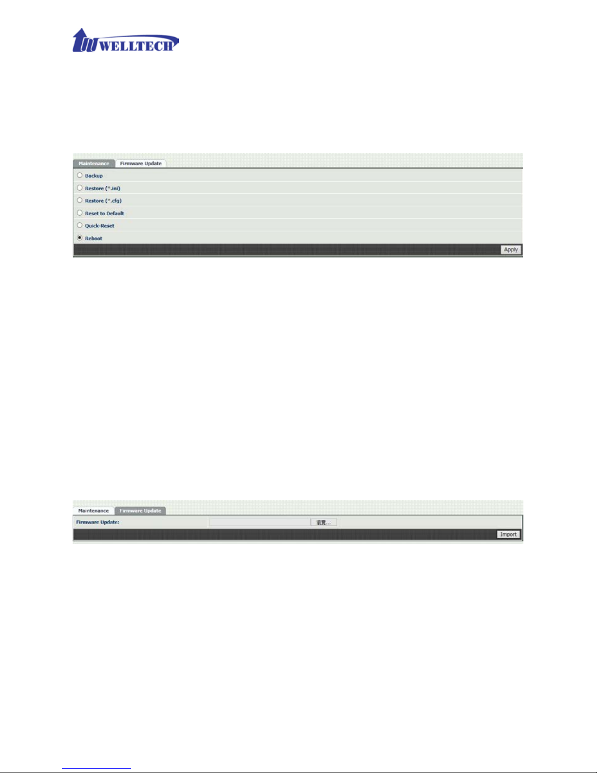
Figure 11-0 Maintenance
Backup: Backup the system settings to y ou r C omp ut er for restoring
purpose.
Restore (*.ini): Restorin g the backu p s etting back to WellGate M4.
Restore (*.cfg): Restoring the auto provision file back to WellGate
M4.
Reset to Default: Reset sys tem setting to factory d efault setting.
Quick-Reset: War m Reset without reboot WellGate M4.
Reboot: reboot WellGate M4.
11-1 Firmware Update
This maintenance page provides the firmware upgrade featur es .
Figure 11-1 firmware update
Firmware Update: Upgrade the new firmware th r ough web page
CH12 Logout
Click the Logout it em to l ogout web page.
Page 59
59
Appendix A --- System Recovery
WellGate M4 use dual firmware image to ensure the system stabilities . In most cases,
you will not encounter the system failed to boot issue. Normally , the user should be able
to use Web page to login and upgrade the firmware through it. If you are not able to do
it, please follow the follow ing step s for recovery.
1. Start the WellGate M4 and to check the STA T US LED is up or not. If STATUS LED is
ON, please press the reset button for 5 seconds to reset to default. After all LED are
light up, the system is back to factory settings.
2. Change your PC IP address to 192.168.123.111 and network set to fix IP address
mode.
3. Connect your PC to LAN port and use http://192.168.123.123 to upgrade the
firmware. Make sure you are using Microsoft IE 8 or above version. Do not support
FireFox or Google Chrome Web browser.
4. If you cannot login to the web page through 192.168.123.123. Open a command
line from windows and type “telnet 192.168.123.123” . If you can see the following
display , go to the next step. Otherwise, please contact Welltech F AE for RMA (Repair)
procedure.
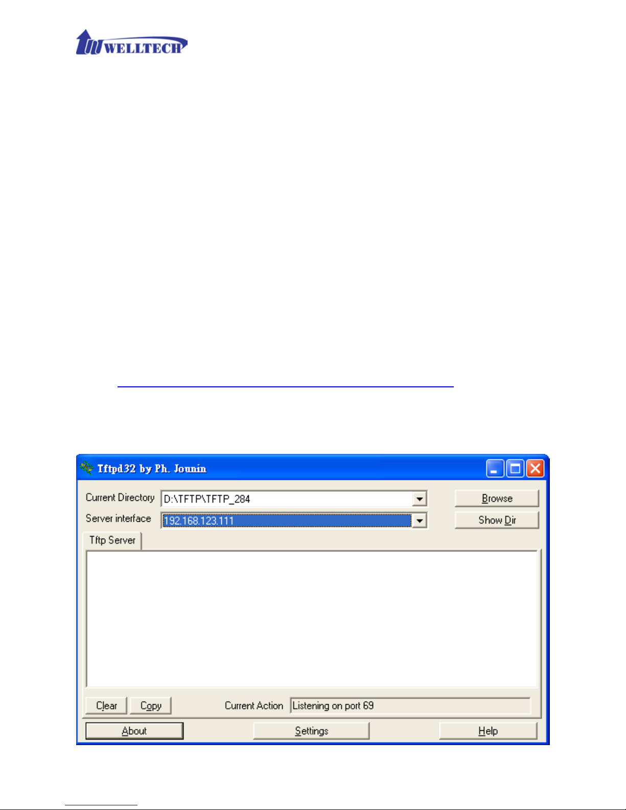
5. Pr e p are a TFTP s er ver for firmware downlo a d as follo w s
- download tftp server
http://www.welltech.com/support/voip/TFTP/TFTP_Server.zip
or
http://tftpd32.jounin.net/tftpd32_download.html
- s tart tftp server
Page 60
60
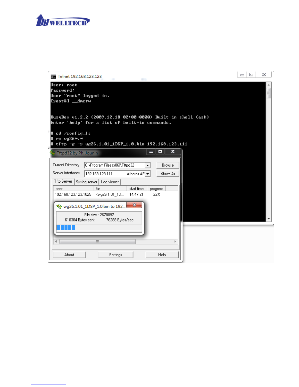
- d ownload the firmware into tftp data directory
6. I n the telne t te rminal, do the following command
- 1. __dmctw
- 2 . cd /config_fs
- 3. rm -f wg26*.bin
- 4 . tftp –g –r wg26.1.01_1DSP_1.0.bin 192.168.123.111
- 4. copy firmware successfully
- 5. reboot
7. Che c k w he ther the syste m was recovered or not
Page 61
61
Appendix B --- HTTP auto provision
Get the http pro vision packet from W elltech and star t the provision as follows:
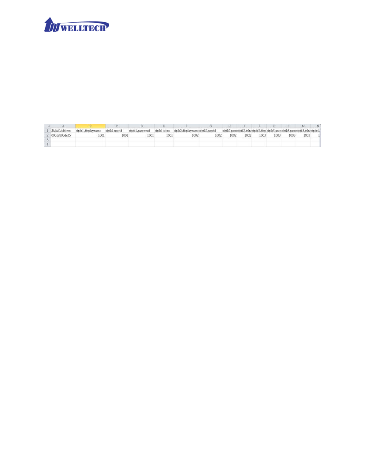
Step 1: build mac l ist for mass configurati on file gene r a tion
For GSM>
WellGate M4 MAC.csv contains most frequent changed parameters as follows:
MACAddress: WellGate M4 MAC Address
Siptk1.displa yname ~ siptk4.displayname: display name for each GSM
line.
Siptk1.userid ~ siptk4.userid: user id f or register to SIP proxy for each line
siptk1.password ~ siptk4.password: user password for register to SIP
proxy of each GSM line
Siptk1.telno ~ siptk4.telno: tel no for each line
Please save and c lose it.
Step 2: create a t emplate configuration file
Open the “WellGate M4 Parameter.txt” getting from Welltech and make the
required change. Please at least make the changes for those settings from
provision and SIP proxy. For detail, please refer to the comments of “wgM4
Parameter.txt”.
Step 3: Make the c h ange for we gencfg.ini as follows if ne c essary
# Template File
BaseFile=.\Wellgate M4 Parameter.txt
# MAC list file
ListFile=.\Wellgate M4 MAC.csv
# 0: Off , 1: On
Encrypt=0
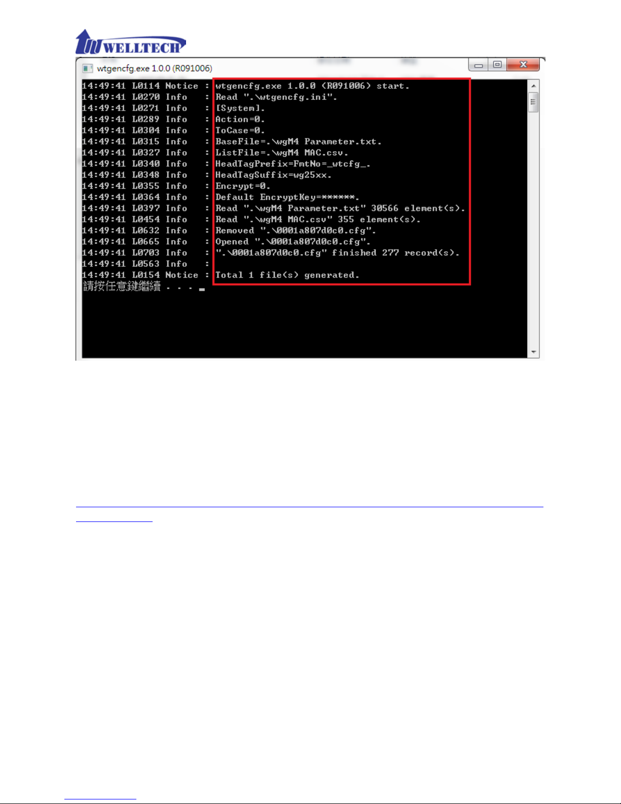
Step 4: Generat e t he individual configura tion file.
Double click the “wtgencfg.exe”, it will generate the config uration file for
each MAC list in “MAC address.cfg” as the following pictures.
Page 62
62
Step 5:
Put the “*.cfg” file into http or ftp direct or y. Set up the provision s ettings in
WellGate M4 an d reboot to test it. Y ou can use the hfs for http f ile server. It can
be downloaded from http://www.rejetto.com/hfs/.
Note: please lin k it to download provision f ile. More information pleas e refer to
“wgM4 Parameter.txt”.
http://www.welltech.com/support/voip2/SIP%20series/FXSO%20series/M4/
Provision.zip
 Loading...