

Page 1

Welltech Computer Co., Ltd.
WellGate 5200 User Guide - V3 - 1 -
Page 2

Welltech Computer Co., Ltd.
CONTENTS
Chapter 1 WellGate5200 Introduction......................................................................4
System Description .................................................................................................... 4
Technical Specification..............................................................................................5
Audio Feature.............................................................................................................5
WellGate5200 Apperance Function Description........................................................6
Chapter 2 Logon WellGate5200.................................................................................7
Logon WellGate5200 .................................................................................................7
Network Configuration .............................................................................................. 9
System Time Configuration .....................................................................................10
Account Manager..................................................................................................... 12
Relogin.....................................................................................................................14
Chapter 3 Gatekeeper Mode Configuration...........................................................16
Environment used in this chapter.............................................................................16
Interface Configuration............................................................................................17
T1/E1 Trunk Configuration......................................................................................19
H.323 Configuration ................................................................................................21
Digit Manipulation................................................................................................... 22
Chapter 4 Call Flow Editor......................................................................................27
Configuration Manager............................................................................................37
Load a configuration management ......................................................................37
Save the working configuration to a selected configuration ...............................38
Apply Change ..........................................................................................................39
Chapter 5 Peer to Peer Mode Configuration..........................................................40
Environment used in this chapter.............................................................................40
Network Configuration ............................................................................................ 40
Account Manager..................................................................................................... 40
Interface Configuration............................................................................................40
Digit Manipulation................................................................................................... 41
Call Flow Editor.......................................................................................................41
H.323 Configuration ................................................................................................42
Address Book........................................................................................................... 43
Configuration Manager............................................................................................45
Apply Change ..........................................................................................................45
Chapter 6 Advance Configuration Reference ........................................................46
Configuration ........................................................................................................... 46
System Configuration........................................................................................... 46
Interface Configuration .......................................................................................47
T1/E1 Trunk Configuration..................................................................................49
H.323 Configuration............................................................................................52
Access Control .....................................................................................................54
Routing Plan ........................................................................................................58
Radius Setting ......................................................................................................60
WellGate 5200 User Guide - V3 - 2 -
Page 3

Welltech Computer Co., Ltd.
Apply Change....................................................................................................... 61
Chapter 7 System Control........................................................................................ 62
System...................................................................................................................... 62
System Time ............................................................................................................62
Network....................................................................................................................62
SNMP.......................................................................................................................63
Prompt Manager.......................................................................................................63
Call Flow Editor.......................................................................................................70
Account Manager..................................................................................................... 70
Upgrade.................................................................................................................... 71
Relogin.....................................................................................................................71
Chapter 8 System Monitor......................................................................................72
Line Summary Status...............................................................................................72
Line Detail ...............................................................................................................73
Event Log................................................................................................................. 73
Debug Info ...............................................................................................................75
Ping ..........................................................................................................................75
Appendix 1 Call Flow Example ...............................................................................76
One Stage Dialing (Gatekeeper Mode).................................................................... 76
One Stage Dialing (Peer to Peer Mode)...................................................................78
Two Stage Dialing (Gatekeeper Mode) ...................................................................80
Two Stage Dialing (Peer to Peer Mode) ..................................................................83
Two Stage Dialing with AAA (Gatekeeper Mode)..................................................86
Appendix 2 Java plug-in Installation ...................................................................... 90
Appendix 3 Retrieve CDR Information..................................................................91
Appendix 4 Quick Start Check List ........................................................................93
Appendix 5 Interface LED Description .................................................................96
Appendix 6 Voice Prompt Index.............................................................................97
Quick Function Reference.........................................................................................98
Index.......................................................................................................................... 103
WellGate 5200 User Guide - V3 - 3 -
Page 4

Welltech Computer Co., Ltd.
Chapter 1 WellGate5200 Introduction
System Description
WellGate 5200 supports ITU-T H.323 V3, SNMP V2, Call Detail Record, WEB
Management and other useful functions. It is a cost effective solution for VoIP trunk
gateway as well as high quality, reliable and full functions to meet customer
requirements.
Wellgate 5200 V3 Features:
- ITUT H.323 v3 and H.450 compliance
- Up to 4 T1/E1 programmable interface
- PSTN signaling: ISDN/PRI, CAS (MFC R2, MFC R1, E&M)
- Support RADIUS billing message and CDR file
- Support mixed Gatekeeper and Peer to Peer modes
- Support fast start, H.245 tunneling, and Early H.245
- Build-in phone book and prefix routing for Peer to Peer mode
- Audio Codec: G.711 (Alaw/Mulaw), G.729A, G.723.1 (5.3K/6.3K)
- Support Silent Suppression for G.729A, G.723
- Support G.168 echo cancellation
- Configurable audio payload size & adaptive jitter buffer
- Automatic voice/fax detection and T.38 fax relay (H.323 Annex D)
- Support in-band and out of band DTMF
- Intelligent PSTN Call Routing
- Flexible digit manipulation plan
- Support access control via ANI, DNIS, IP, Gatekeeper call or RADIUS
- Build-in IVR & call-flow controller
Web-based GUI Drag and Drop interface
Full control of call behavior (one-stage or two-stage dialing)
IVR functions
Support time duration play back (Chinese & English)
Power call information branch
Collected information validation
Active disconnect & reconnect without hang up
Selected disconnect cause code & behavior
Build-in internal AAA for debit & credit user
- Web-based graphic announcement management
- SNMP v2 (H.341) and SNTP support
- User account management
- Full Web management interface & real time monitor
- Multiple configuration saving
WellGate 5200 User Guide - V3 - 4 -
Page 5

Welltech Computer Co., Ltd.
Technical Specification
Interface
• Two 10/100MB Ethernet Ports (Auto Negotiation)
• Up to 4 T1/E1 (120 Ohm-RJ48C connectors [75 Ohm = with external 3
rd
party
BNC/RJ-48C adapter cables])
programmable interface
Protocol and Standard
• ITUT H.323 v3 and H.450 compliance
•
SIP/MGCP (**)
Audio Feature
• Codec -- G.711 A/µ-Law, G.723.1 (5.3K/6.3K), G.729A
• Support G.168 echo cancellation
• Configurable audio payload size & adaptive jitter buffer
• Support in-band and out of band DTMF
FAX Support
• Automatic voice/fax detection and T.38 fax relay (H.323 Annex D)
• Up to G3 FAX
• CISCO compatible
Management Feature
• Full Web management interface & real time monitor
• SNMP v2 (H.341) and SNTP support
• User account management
LED indicators for system status
• POWER: Power/DOC access
Power
• 90~240V auto switch
Environmental
• Operation temp: 0° C to 60° C
• Relative humidity: 5% to 95%
Dimension
• 483mm(L) x 450 mm(W) x 44mm(H)
WellGate 5200 User Guide - V3 - 5 -
Page 6

Welltech Computer Co., Ltd.
WellGate5200 Apperance Function Description
WellGate5200 Front Panel:
4
5
6
3
2
1
Functions:
1: Electric Fan
2: Keyboard
3: USB interface
4: Hard disk button activity indicator
5: Reset key
6: Power indicator
WellGate5200 Rear Panel:
1
1
1
7
8
9
4
6
5
3
2
1
Functions:
1: Electric Fan
2: AC Power outlet
3: AC Power switch (Keep on)
4: Com2 port (not available)
5: Trunk E1/T1 port
6: VoIP Enternet port
7: Keyboard
8: Mouse
9: Com1 port
10: Enternet port
11: VGA
12: print port (not available)
WellGate 5200 User Guide - V3 - 6 -
Page 7

Welltech Computer Co., Ltd.
Chapter 2 Logon WellGate5200
After connected E1/T1 & Ethernet cables into the WellGate5200, turned on the
power. The first step is to logon the system and set up the IP address.
Before you can use the Browser to config WellGate5200, you need to have
Java Standard Runtime (1.3.1 or later version) to make it work. Please refer to
Appendix 2 Java plug-in Install
for detail.
Logon WellGate5200
Setp1: Start IE5.0 (or later version) to navigate WellGate5200 Management System
by typing the default IP address (the default URL is
http://192.168.111.111:10087). The screen will display User ID and
Password as figure 2.1-1.
Figure 2.1-1
Note: The default network IP address is 192.168.111.111 and subnet mask is
255.255.0.0
WellGate 5200 User Guide - V3 - 7 -
Page 8

Welltech Computer Co., Ltd.
Step 2: Enter log user name and password (the default user id is root and user
password is root). You can manage your user account via web (refer to
Section “Account Manager
”) as figure 2.1-2.
Figure 2.1-2
Step 3: The screen shows the Home Page of WellGate5200 as figure 2.1-3.
Figure 2.1-3
WellGate 5200 User Guide - V3 - 8 -
Page 9

Welltech Computer Co., Ltd.
Network Configuration
Step 1: After successfully logon to the system, we need to change the network
configuration. Click Control→Network to setup the network parameters as
figure 2.2-1.
Figure 2.2-1
Step 2: Enter the deserved IP address, Submask and default gateway. Apply the
change by clicking apply button as figure 2.2-2.
Figure 2.2-2
WellGate 5200 User Guide - V3 - 9 -
Page 10

Welltech Computer Co., Ltd.
Step 3: When screen shows “Setup network configuration successfully!” It means
the IP Network setting is successfully changed as figure 2.2-3.
Figure 2.2-3
Note: “Network Control” takes around 5-second to apply the new network
configuration. Please logon again with new IP address after 5 seconds.
System Time Configuration
Step 1: When relogon to the new IP address; the next is to setup the system time.
Click Control→System Time to setup the system time as figure 2.3-1.
Figure 2.3-1
WellGate 5200 User Guide - V3 - 10 -
Page 11

Welltech Computer Co., Ltd.
Step 2: Click Time Zone button to setup the System Time Zone as figure 2.3-2.
Figure 2.3-2
Step 3: Enter current date and time. Apply the change by clicking Apply button as
figure 2.3-3.
Figure 2.3-3
Step 4: The screen will shows “Setup system time successfully!” It means the
System Time setting is successfully changed as figure 2.3-4.
Figure 2.3-4
WellGate 5200 User Guide - V3 - 11 -
Page 12

Welltech Computer Co., Ltd.
Step 5: If you would like to use SNTP to sync time with a SNTP V4 Server, click
Time Sync button to setup it as figure 2.3-5.
Figure 2.3-5
Account Manager
Step 1: You can manage your user account by click Control→Account Manager. To
add a new user account, Click New button as figure 2.4-1.
Figure 2.4-1
WellGate 5200 User Guide - V3 - 12 -
Page 13

Welltech Computer Co., Ltd.
Step 2: Enter the new user ID, password, user role and description, as you need.
Apply the change as figure 2.4-2.
Figure 2.4-2
Field Description:
• User ID: Login User ID
• Password: Login Password
• Confirm Password: Confirm new password again
• User Role: User Role
- Admin (Administrator)
- Operator
• Description
Step 3: When screen shows “Create user account successfully!” It means user
account setting is successfully created as figure 2.4-3
Figure 2.4-3
Note: The system provides 2 USER ID by default:
User 1: “root” Password: “root”
User 2: “admin” Password: “admin”
WellGate 5200 User Guide - V3 - 13 -
Page 14

Welltech Computer Co., Ltd.
Relogin
Step 1: Click Control→Relogin to relogon by another user account as figure 2.5-1.
Figure 2.5-1
Step 2: Enter new User ID and Password to relogon the WellGate5200 as figure 2.5-2.
Figure 2.5-2
WellGate 5200 User Guide - V3 - 14 -
Page 15

Welltech Computer Co., Ltd.
Step 3: The screen shows the Home Page of WellGate5200 as figure 2-5-3.
Figure 2.5-3
WellGate 5200 User Guide - V3 - 15 -
Page 16

Welltech Computer Co., Ltd.
Chapter 3 Gatekeeper Mode Configuration
Environment used in this chapter
PSTN incoming calls
WellGate5200
Prefix: 5
PSTN
T1 /E1
IP
LanPhone
E164: 1001
Gatekeeper
H.323 incoming calls
Gatekeeper Mode
Call Flow:
PSTN → DNIS (02822656991001) → Inbound DM (PSTN_in_drop) → Make
Call (1001)
H.323 → DNIS (5933111222) → Inbound DM (H.323_out_drop) → Make Call
(0932111222)
* Digit Manipulation: Please refer section “Digit Manipulation
”
WellGate 5200 User Guide - V3 - 16 -
Page 17

Welltech Computer Co., Ltd.
Interface Configuration
This section is going to setup the VoIP interface.
Step 1: Now we are going to setup the VoIP interface, click Configuration→
Interface to setup VoIP T1/E1 interface as figure 3.2-1.
Figure 3.2-1
Step 2: Double-click the installed interface (i.e Interface ID:0) to config it as figure
3.2-2.
Figure 3.2-2
WellGate 5200 User Guide - V3 - 17 -
Page 18

Welltech Computer Co., Ltd.
Step 3: Modify the VoIP Interface parameters (i.e. IP Address, Protocol Tag, Subnet
Mask and Default gateway) and apply the change by clicking Apply as
figure 3.2-3.
Figure 3.2-3
Frequency changed parameters: (Refer to section “Interface Configuration” for
more detail)
• IP Address: 192.168.111.204
• Subnet Mask: 255.255.255.0
• Default Gateway: 192.168.111.254
• Clock Source: External or internal (for PSTN)
• PCM Type: A-law or Mulaw
CAUTION: Subnet Mask does not support Supernet.
Step 4: After successfully to changed the Interface configuration, the screen come
back the page of Interface Configuration as figure 3.2-4.
Figure 3.2-4
WellGate 5200 User Guide - V3 - 18 -
Page 19

Welltech Computer Co., Ltd.
T1/E1 Trunk Configuration
This section is going to setup the PSTN trunk parameters.
Step 1: Select the installed interface to modify the trunk parameter by click Detail
button as figure 3.3-1.
Figure 3.3-1
Step 2: Select the trunk to be modified, and click Modify button as figure 3.3-2.
Figure 3.3-2
WellGate 5200 User Guide - V3 - 19 -
Page 20

Welltech Computer Co., Ltd.
Step 3: Modify the trunk parameters (i.e. Trunk Type, Termin Side, Trunk Mode,
Protocol Tag, Line Code) and apply the change by clicking Apply as figure
3.3-3.
Figure 3.3-3
Frequency Changed Parameters:
• Trunk Type: E1 or T1
• Termin Type: User Side or Network Side
• Trunk Mode: Normal
• Protocol Tag: ISDN protocol used
• Line Code: T1 or E1 line code used
• Inbound DM Group: PSTN_in_drop (refer to section “Digit Manipulation
”)
Step 4: After successed to change the Trunk Configuration, the screen come back the
page of Trunk Configuration as figure 3.3-4.
Figure 3.3-4
WellGate 5200 User Guide - V3 - 20 -
Page 21

Welltech Computer Co., Ltd.
H.323 Configuration
This section is going setup the H.323 parameter.
Step 1: Click Configuration→H.323 to configure the H.323 parameters as figure
3.4-1.
Figure 3.4-1
Step 2: Enter the correct parameter for deserved Gatekeeper mode, Gatekeeper IP,
E.164 and Register H.323 ID, Inbound DM Group and apply the change as
figure 3.4-2.
Figure 3.4-2
Frequency used parameters:
• Register to Gatekeeper: Yes
• Gatekeeper IP: 192.168.111.1
• E.164 Tel: 203
• Register H.323 ID: 203
• Outbound DM Group: H.323_in_drop (refer to section “Digit Manipulation”)
WellGate 5200 User Guide - V3 - 21 -
Page 22

Welltech Computer Co., Ltd.
Step 3: You can see the screen display the new configuration of the H.323
Configuration as figure 3.4-3.
Figure 3.4-3
Digit Manipulation
The purpose of “Digit Manipulation” is to add or drop dialed digits for PSTN
or IP side (Interface configuration for PSTN side & H.323 Configuration for IP side)
at the selected interface in order to meet local PSTN dialing requirement. It can also
be used in Call Flow Edit for flexible usage.
Step 1: We introduced the group and interface dependent digital manipulation to meet
the customer’s requires. Click Digit Manipulation to add a new Digit
Manipulation Group, add as figure 3.5-1.
Figure 3.5-1
WellGate 5200 User Guide - V3 - 22 -
Page 23

Welltech Computer Co., Ltd.
Step 2: Enter the related parameters and click Apply button as figure 3.5-2.
Figure 3.5-2
Field Description:
• Group ID:0 (Use to identify the DM Group)
• Description: H323_In_Drop
Step 3: When you see the screen with the new added DM Group, Select the new
created DM Group and click Detail button to add digits setting as figure 3.5-
3.
Figure 3.5-3
WellGate 5200 User Guide - V3 - 23 -
Page 24

Welltech Computer Co., Ltd.
Step 4: Click New button to add a new DM rule as figure 3.5-4.
Figure 3.5-4
Step 5: Create a new DM Group and DM record (H.323 incoming calls), enter the
related parameters (i.e H323_in_drop) and apply as figure 3.5-6.
Figure 3.5-6
Field Description:
• Matched Pattern: 5 (pattern to be matched)
• Group ID: 1-H323_In_Drop (belong to this DM group)
• Drop: 5 (drop digits)
• Insert: 0 (inset digits)
Example 1 Description:
H.323 incoming calls
↓
Dialed number: 5932111222
WellGate 5200 User Guide - V3 - 24 -
Page 25

Welltech Computer Co., Ltd.
↓
Match the pattern 5
↓
Delete 5 (Drop)
↓
Add 0 (Insert)
↓
New dialed number becomes 0912111222
Example 2 Description:
H.323 incoming calls
↓
Dialed number: 50282221111
↓
Match the pattern 502
↓
Delete 502 (Drop)
↓
New dialed number becomes 82221111
Step 6: Create another DM Group and DM record (PSTN incoming calls), enter the
related parameters (i.e PSTN_out_drop) and apply as following description
the changes as figure 3.5-7.
Figure 3.5-7
Field Description:
• Matched Pattern: 0282265699 (pattern to be matched)
• Group ID: 4-PSTN_in_drop (belong to this group id)
WellGate 5200 User Guide - V3 - 25 -
Page 26

Welltech Computer Co., Ltd.
• Drop: 0282265699 (drop digits)
Example Description:
PSTN incoming calls (DNIS mode)
↓
Dialed number: 02822656991001
↓
Match the pattern 0282265699
↓
Delete 0282265699 (Drop)
↓
New dialed number becomes 1001
Step 6: You can see the screen display the new configuration DM as figure 3.5-8
Figure 3.5-8
Note: Digit Manipulation have to tapped for PSTN Side (Trunk→
Outbound/Inbound DM Group), H.323 Side (H.323→Outbound/Inbound
DM Group) or Call Flow (refer to section “Call Flow Editor”) to take
WellGate 5200 User Guide - V3 - 26 -
Page 27

Welltech Computer Co., Ltd.
Chapter 4 Call Flow Editor
Call Flow Editor is used to control the call behavior including voice prompt,
AAA, DM…etc. It requires Java run time to run.
Step 1: Click Control→Call Flow Editor to create a Call Flow, click
button to
activate IVR Tool as figure 4-1
Figure 4-1
Component Description:
• New: Create a new call flow
•
Load Call Flow: Load call flow from WellGate5200
• Save: Save a call flow in WellGate5200
•
Cut: Cut a component
•
Copy: Copy a component
• Paste: Paste a component
• Delete: Delete a component
•
Line: Connecting 2 components together
• Select: Select the component at call flow workspace
•
Scroll: Scroll the call flow workspace
• Zoom: Zoom in or zoom out the workspace
• View Grid: View or not
• Show Component Table: Show all component table
WellGate 5200 User Guide - V3 - 27 -
Page 28

Welltech Computer Co., Ltd.
Step 2: Drag and prop the required component icon into the workspace as figure 4-2.
Figure 4-2
Right click the component to bring up the component propriety to setup
parameter:
•
AAA: Send Authorization for validation
o Success To: Success to component
o Failed To: Failed to component
•
Answer: Answer incoming call (PSTN only)
•
Branch: Play an announcement and branch into different route
o Voice File: Voice prompt file (“. raw” format) to be playing
o DTMF Length: Number of DTMF to be receiving
o Others: Default flow if not match
o DTMF: DTMF match pattern
WellGate 5200 User Guide - V3 - 28 -
Page 29

Welltech Computer Co., Ltd.
o Goto: The next component if matched
o Line Propriety:
-Branch Line: DTMF branch line setting
• CDV: Collected Digit Validation
o Check Parameter: Check parameter type (DNIS, ANI….)
o Digit From: Start digit from
o Digit To: End digit to
o Valid To: If the checked variable is success to validate
o Invaried To: If the checked variable is not success to validate
•
CIB: Call Information Branch
o Info Type: Information type selection
o Prefix: The prefix to be match
o Goto: The component to run next
o Call Info Branch Line: DTMF goto setting
WellGate 5200 User Guide - V3 - 29 -
Page 30

Welltech Computer Co., Ltd.
•
CIV: Call Information Validation, the user need setup the ACL for DNIS
and IP TO take effect
o Info Type: The infor type to be validation
-DNIS: Called number
-ANI: Calling number
-IP: In coming IP address
-User: User ID
o Allow To: If it is met the ACL difired
o Disallow To: If it isnot met the ACL difired
•
CTB: Calling type Branch
o PSTN To: If PSTN incoming call
o H.323 To: If H.323 incoming call
•
Cut Rule: Cut a system variable into different parts
o Cut From: Cut start digit from (start from 1)
o Cut To: Cut end digit to
o Assign To: Store the cutted result into
WellGate 5200 User Guide - V3 - 30 -
Page 31

Welltech Computer Co., Ltd.
• Disconnect: Disconnect the call
o PSTN: PSTN disconnect reason code:
-Normal Call Clear
-User Busy
-No User Response
-No Answer
-Call Reject
o H.323: H.323 disconnect reason code:
-No Bandwidth
-Unreachable Destination
-Destination Rejection
-No Permission
-Unreachable Gatekeeper
•
DM: Digit Manipulation
o DM Parameter: Manipulation ANI or DNIS
o DM Group ID: Apply to DM group
•
MakeCall: Make Call to PSTN or H.323 site
WellGate 5200 User Guide - V3 - 31 -
Page 32

Welltech Computer Co., Ltd.
o Route Mode: Gatekeeper Call or P2P Call or PSTN…etc. (for PSTN
incoming call, please select the Gatekeeper, P2P Call, TA (for H.323
incoming call, please select the PSTN call)
o Transport Address: When used for “TA” routing mode, the format used is
“Ipaddr:port” (e.g. 192.168.111.50:1720)
o Active Disconnect: Enable PSTN user can actively disconnect the call or
not
o Active Disconnect Digit: The DTMF digit to be tread as the disconnect
trigger. Only can be used “Active Disconnect” enable
o Active Disconnect To: The next component when active disconnect is
occurred
o Inter Digit Timeout: The max time to in seconds to wait between two
digits.
o Finish To: Successfully connect to remote site
o Failed Other to: The next component when default failed call
o Failed Reason: Failed reason selection
o Failed To: When the failed reason occurred go to
o Line Propriety:
-PSTN: PSTN disconnect reason code:
-Normal Call Clear
-User Busy
-No User Response
-No Answer
-Call Reject
- H.323: H.323 disconnect reason code:
-No Bandwidth
-Unreachable Destination
-Destination Rejection
-No Permission
-Unreachable Gatekeeper
•
PA: Play Announcement
o Dynamic Play: Dynamic play voice file by combine prefix and variable as
the file name
o Enable: Combine prefix to variable as the voice file to play
-Prefix: Voice file prefix (e.g. prefix: WT, variable: user1 (contact 201,
played voice file is “WT201.raw”)
-Variable: Variable to be appending as the voice file name
o Disable: Use filter voice prompt file
-Voice File: Voice prompt file
WellGate 5200 User Guide - V3 - 32 -
Page 33

Welltech Computer Co., Ltd.
o Interrupted: Voice can be interrupted or not
• PCUI: Prompt and Connect User Information
o Play Type: Dial tone or voice prompt selection
o Voice File: Voice prompt file
o Max DTMF: Maxtor of DTMF to be received.
o Assign To: Result (received DTMF) will be assign to
o End of DTMF: The digit to indicate dial end.
•
PD: Play Duration for prepaid purpose
o Voice File: Leading voice prompt file
o Language: Play duration language section
-English
-Chinese
The RADIUS servers need to be setup to send H.323 credit time or internal
RADIUS must be used.
•
PSTN L.H: PSTN Line Hunting
o Success To: If fine an available channel by system setup (call hunting)
o Failed To: If not fine an available channel by system setup (call hunting)
WellGate 5200 User Guide - V3 - 33 -
Page 34

Welltech Computer Co., Ltd.
• Set Data: Assign value to a variable
o Assign To: Assigned variable
o Use SysParam: Use system parameter to replace or not
o Value: ANI, DNIS, User ID or other digits
•
Start: Call flow start
o Next Component
•
Quit: Disconnect calls
WellGate 5200 User Guide - V3 - 34 -
Page 35

Welltech Computer Co., Ltd.
Example Call Flow as figure 4-3.
Figure 4-3
Used components:
Start 1001
(Start)
• Next Component: 1032
CTB 1032
(Call Type Branch)
• PSTN To: 1105
• H.323 To: 1104
1104 Route for H.323 call
MakeCall 1004
(Connecting Call)
• Route Mode: PSTN
• Finish To: 1006
• Failed Other To: 1006
Disc 1006
(Disconnect)
• Reason: PSTN normal call clear
1105 Route for PSTN call
Answer 1105
(Answer)
• Next Component: 1101
WellGate 5200 User Guide - V3 - 35 -
Page 36

Welltech Computer Co., Ltd.
PCUI 1101 (Prompt and connect user information)
• Play Type: Voice
• Max DTMF: 8
• Result Append To: DNIS
• End of DTMF: #
• Next Component: 1096
MakeCall 1096
(Connecting Call)
• Route Mode: Gatekeeper Call
• Finish To: 1006
• Failed Other To: 1006
Disc 1006 (Disconnect)
• Reason: PSTN No normal call clear
Call Flow:
Make Call: 1004
Call to PSTN
Start:1000
CTB
1032
PCUI:1001
Voice:
Please Input
Telephone Number
Answer:1105
(Off-Hook)
1105
PSTN in
Make Call: 1096
Make
Gatekeeper
call to H.323
1104
H.323 in
Disc: 1006
Disconnect
Finish to
Failed other to
Finish to
Failed other to
WellGate 5200 User Guide - V3 - 36 -
Page 37

Welltech Computer Co., Ltd.
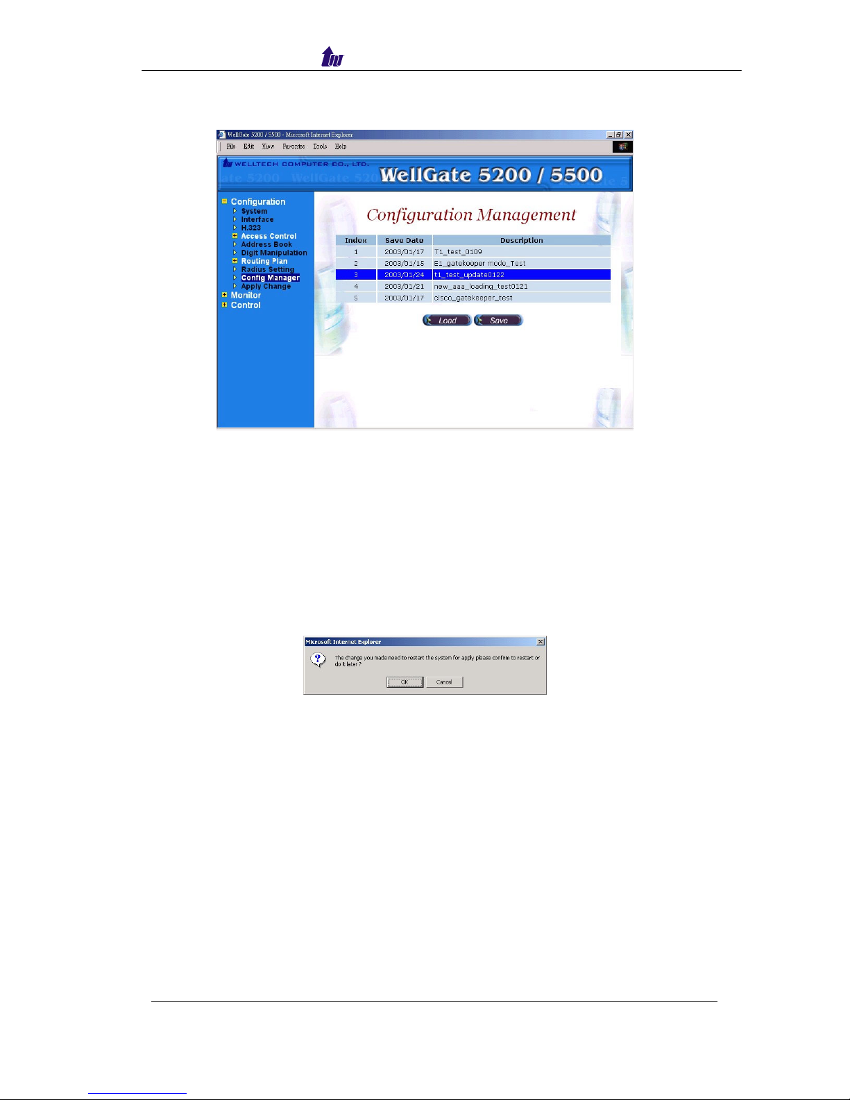
Configuration Manager
Configuration Management provides a way to save and reload the system
configuration for future use.
Load a configuration management
Step 1: When you need to load a saved configuration, click the saved configuration
(i.e.02/10 CAS-CHINA) item to load it back as figure 4.1-1.
Figure 4.1-1
Step 2: When screen shows “Current configuration will lost!! Are you sure to load
this configuration?” Click on OK button to load the saved configuration to
the working configuration as figure 4.1-2.
Figure 4.1-2
Step 3: When the screen shows “Load configuration successfully!” It means the
save configuration is successfully loaded into the working configuration as
figure 4.1-3.
Figure 4.1-3
Note: It is need to restart to take effect of the new-loaded working
configuration.
WellGate 5200 User Guide - V3 - 37 -
Page 38

Welltech Computer Co., Ltd.
Save the working configuration to a selected configuration
Step 1: To save the current configuration, select a new created configuration and click
save as figure 4.2-1.
Figure 4.2-1
Step 2: when screen shows “Description”, please enter the configuration description
(i.e. Gatekeeper_mode_update) for the saved configuration as figure 4.2-2.
Figure 4.2-2
Step 3: When screen shows “Create configuration successfully!” It means
configuration management is successfully save as figure 4.2-3.
Figure 4.2-3
WellGate 5200 User Guide - V3 - 38 -
Page 39
Welltech Computer Co., Ltd.
Step 4: You can see the screen display the changes as figure 4.2-4.
Figure 4.2-4
Apply Change
When you load a new working configuration, the system must be restarted to
take effect.
Step 1: Click Configuration→Apply Change, the screen show “ The change you
mode need to restart the system for apply please confirm to restart or do it
later.” Click on OK/Cancel to restart the system or not as figure 4.3-1.
Figure 4.3-1
WellGate 5200 User Guide - V3 - 39 -
Page 40

Welltech Computer Co., Ltd.
Chapter 5 Peer to Peer Mode Configuration
Environment used in this chapter
P
H.323 incoming calls
STN incoming calls
WellGate5200
Prefix: 5
PSTN
T1 /E1
IP
LanPhone
E164: 1001
Peer-to-Peer Mode
Process:
PSTN → DNIS (02822656991001) → Inbound DM (PSTN_in_drop) → Make
Call (1001)
H.323 → DNIS (5932111222) → Inbound DM (H.323_out_drop) → Make Call
(0932111222)
* Digit Manipulation: Please refer section “Digit Manipulation
”
Network Configuration
Please refer to section “Network Configuration”
Account Manager
Please refer to section “Account Manager”
Interface Configuration
Please refer to section “Interface Configuration”
WellGate 5200 User Guide - V3 - 40 -
Page 41

Welltech Computer Co., Ltd.
Digit Manipulation
Please refer to section “Digit Manipulation”
Call Flow Editor
Please refer to section “Call Flow Editor”
Call Flow (P2P Mode):
Make Call: 1004
Call to PSTN
Start:1000
CTB
1032
PCUI:1001
Voice:
Please Input
Telephone Number
Answer:1105
(Off-Hook)
1105
PSTN in
Make Call: 1096
Make
Peer to Peer
call to H.323
1104
H.323 in
Disc: 1006
Disconnect
Finish to
Failed other to
Finish to
Failed other to
WellGate 5200 User Guide - V3 - 41 -
Page 42

Welltech Computer Co., Ltd.
H.323 Configuration
Step 1: Click Configuration→H.323 to configure the H.323 parameters as figure
4.7-1.
Figure 4.7-1
Step 2: Change Register To Gatekeeper to “No” to enable peer to peer mode as
figure 4.7-2.
Figure 4.7-2
Frequency used parameters:
• Register to Gatekeeper: No
• Outbound DM Group: H.323_out_drop
WellGate 5200 User Guide - V3 - 42 -
Page 43

Welltech Computer Co., Ltd.
Step 3: You can see the screen display the new configuration of the H.323
Configuration as figure 4.7-3.
Figure 4.7-3
Address Book
For making a Peer-to-Peer call, the IP device must has an address record in
the phone book for routing.
Step 1: Click Address Book adds a new address book for the peer to peer calls, New
to add as figure 4.8-1.
Figure 4.8-1
WellGate 5200 User Guide - V3 - 43 -
Page 44

Welltech Computer Co., Ltd.
Step 2: Enter the related parameters and click Apply button as figure 4.8-2.
Figure 4.8-2
Field Description:
• Name: Lanphone1001
• Tel/Prefix: 1001
• Trans Address: 192.168.111.102 or 192.168.111.102:1720
Step 3: You can see the screen displays the new Address Book as figure 4.8-3.
Figure 4.8-3
Note: You must apply the change to take effect for the change.
WellGate 5200 User Guide - V3 - 44 -
Page 45

Welltech Computer Co., Ltd.
Configuration Manager
Please refer to section “Configuration Manger”
Apply Change
Please refer to section “Apply Change”
WellGate 5200 User Guide - V3 - 45 -
Page 46

Welltech Computer Co., Ltd.
Chapter 6 Advance Configuration Reference
Configuration
System Configuration
Start Path: Configuration→System
Figure 6.1-1
Parameter Description:
• CDR Mode: Call detail record generating mode (Refer to “Appendix 3 Retrieve
CDR Information” for detail file description)
o File Only: Log CDR into the file only. It can be retrieved by ftp (directory
c:\welltech\CDR).
o Radius Start/Stop: Log CDR into the file and send RADIUS start/stop billing
message out.
- VoIP: enable VoIP site RADIUS billing message or not.
- PSTN: enable PSTN site RADIUS billing message or not.
o Radius Stop: Log CDR into the file and send RADIUS stop billing message
out.
- VoIP: enable VoIP site RADIUS billing message or not.
- PSTN: enable PSTN site RADIUS billing message or not.
• CDR Keepdays: CDR system keeping days
• Hot Swappable: Hot swappable support (reserved)
• First Digit Timeout: The max to time (in second) waits for receiving the first
digit entered (5~20 sec).
• Inter Digit Timeout: The max to time (in second) waits for the between two
digits (5~20 sec).
• Debug Level:
WellGate 5200 User Guide - V3 - 46 -
o Critical: Show critical error messages only
Page 47

Welltech Computer Co., Ltd.
o Warring: Show warring and critical error message only
o Information: Show information, warring and critical message only
o Debug: Show all debug messages
o Full Trace: Show all status and debug messages
Note: Please set to “Critical” only, or the whole system performance will be hitted.
• Time Expired Notify: Seconds to be notifying caller before communication
expired. This function is used for Pre-Paid calling card service and must
cooperate with RADIUS Server.
• Almost Expired Tone: Communication expired notice tone selection
o Notify Tone#1:
o Notify Tone#2:
Interface Configuration
Start Path: Configuration→Interface
Figure 6.2-1
Basic Parameter Description:
• Interface ID: System parameter
• Card slot: System parameter
• Interface Type: System parameter
• Description: System parameter
• Serial No: System parameter
• License Key: System parameter
• IP Address: IP address used for voice RTP stream
• Subnet Mask: Submask (doesn’t support super class)
• Default Gateway: Default gateway for routing
• Clock Source: PSTN clock source for TDM sync
o Internal: derived from internal oscillator
o External: derived from external PSTN E1/T1 clock
• PCM Type: PCM type encoding, E1 A-law; T1 u-law
WellGate 5200 User Guide - V3 - 47 -
Page 48

Welltech Computer Co., Ltd.
Advance Interface Configuration:
Start Path: Configuration→Interface →Advance
Figure 6.2-2
Advance Parameter Description:
• Interface ID: System parameter
• UDP Port Base: UDP port used for RTP stream, each channel needs 3 RTP
ports and must be started by a multiple of 10
• IP Precedence: Voice package priority setting
o Routine Precedence
o Priority Precedence
o Immediate Precedence
o Flash Precedence
o Flash Override Precedence
o Critical Precedence
o Internetwork Precedence
o Network Precedence
• IP TOS: Top of Service with the following priority selection
o Normal Service
o Minimize Monetary
o Maximize Reliability
o Maximize Thought
o Minimize Delay
• PCM Idle Pattern: This pattern will be sending on each B channel PCM time
slot when the channel is idle (not connected). The default value for A-Law is
0xff and for Mu-Law is 0x55. You only change it when SWITCH need.
• CAS Idle Pattern: When channel is idle, ABCD (CAS) pattern to be applied
CAS signaling bus
• Jitter Min Delay: The minimum delay time of Jitter buffer. The range is 0 to
150ms. Default value is 150ms. Which has better voice quality but the delay
time will be long.
WellGate 5200 User Guide - V3 - 48 -
Page 49

Welltech Computer Co., Ltd.
• Jitter Opt Factor: Jitter buffer optimization factor from 0 to 12. The default
value is 7. Set to 0 will have lowest voice delay but have bad voice quality. Set
to 12 will have long voice delay but with better voice quality
• EC Tail Length: Echo Cancellation Length, default value is 25ms
• Silence Compress: Enable silence compress or not
T1/E1 Trunk Configuration
Start Path: Configuration→Trunk
Figure 6.3-1
Basic Parameter Description:
• Interface ID: System parameter
• Trunk ID: System parameter
• Trunk Type: T1or E1 selection
• Description: Description for this trunk ID
• Termin Side: Network site or User Site (normally, you set to “user site” when
connect to switch)
o User Side
o Network Side
• Trunk Mode: Trunk operation mode
o Disable: Disable the trunk
o Normal: Accept PSTN and VoIP calls
o PSTN incoming only: Allow the PSTN incoming calls only
o H.323 incoming only: Allow the H.323 incoming calls only
• Hunting Method: PSTN trunk hunting method for available channel
o Random: Hunt randomly
o Cyclic: Initial hunt (after power-up/reboot) begins with B channel 1;
subsequent hunts begin with position following last successfully allocated
resource
o Rotary: Hunt always begins with B channel 1
• CAS Variance: CAS counting variance
• Framing Method:
WellGate 5200 User Guide - V3 - 49 -
Page 50

Welltech Computer Co., Ltd.
o For T1
- super frame
- 4-frame multi-frame
- 12 frame multi-frame (D4)
- extend super frame without CRC6
- extend super frame with CRC6
- 72-Frame Multi-Frame
o For E1:
- Automatic CRC4 or Double Frame selection
- Double Frame Format
- CRC4 multi-frame
- CRC4 extend multi-frame
• Protocol Tag: supported protocol on T1/E1 interface with PSTN switch
o For T1:
- T1 CAS
- T1 NI2 ISDN
- T1 4ESS ISDN
- 5ESS 9 ISDN
- 5ESS 10 ISDN
- T1 DMS100 ISDN
- T1 NTT ISDN used to connect NTT INS-1500 ISDN standard (Japan Only)
o For E1:
- E1 EURO ISDN: used for most of European ISDN standard
- E1 MFCR2
- E1 CAS R2
- E1 AUSTEL ISDN: Australia E1 ISDN Variance
- E1 HKT ISDN: Hong E1 ISDN Kong Variance
- E1 KOR ISDN: Korea E1 ISDN Variance
• Line Code: T1: you can choose AMI, B8ZS; E1: you can choose AMI, HDB3
• PSTN Trace: PSTN layer debug trace. It will generate a debug trace file for
tracing purpose. Only enables it under Welltech technical supports instruction
and disable it when complete the debug
• Inbound DM Group: Digit Manipulation group used for incoming calls
associated to this trunk
• Outbound DM Group: Digit Manipulation group used for outgoing calls
• Local Ring Back: Provide ring back tone for PSTN or not. It only works when
H.323 outgoing Fast Start is disabled.
WellGate 5200 User Guide - V3 - 50 -
Page 51

Welltech Computer Co., Ltd.
Advance Trunk Configuration:
Start Path: Configuration→Interface →Trunk →Advance
Figure 6.3-2
Advance Parameter Description:
• Interface ID: System parameter
• Trunk ID: System parameter
• Dest Num Plan: ISDN destination number plan
• Src Num Type: ISDN source number type
• Dest Num Type: ISDN destination number type
• Src Num Presen: ISDN source number presentation
• Src Num Screen: ISDN source number display
• Input Gain: Voice Gain from IP to PSTN side (default: 0 db)
• Output Gain: Voice Gain from PSTN to IP side (default: 0 db)
• Q.931 General Opt.: used for Q.931 general behavior.
o 0x0001: No Status message send for unknown facility IE if it is set
o 0x0002: No Status message send for invalid content of a valid facility IE if
it is set
o 0x0080: Send Connect Ack message when receive Connect message if it is
set, you can OR the required option together
• Q.931 Incoming Opt.: used for Q.931 incoming call behavior
o 0x0800: include Channel-ID IE in the first reply message (e.g. Call
Proceeding or Alerting)
o 0x2000: enable the system to include Channel-ID IE in the Call
Proceeding message, you can OR the required option together
• Q.931 Outgoing Opt.: used for Q.931 outgoing behavior
o 0x0010: use Mu-law if this bit is set, or A-law will be used. Apply only for
Korea variance, you can OR the required option together
• Trans Cap: Transfer Capability
o Voice Service
o Date Service
o Modem Service
WellGate 5200 User Guide - V3 - 51 -
Page 52

Welltech Computer Co., Ltd.
• CallID Transfer Type: Call ID transfer type
o Disable Caller ID: default parameter
o Transparent Caller ID
o Relay Caller ID
o Bypass Caller ID
H.323 Configuration
Start Path: Configuration→H.323
Figure 6.4-1
Basic Parameter Description:
• Register To Gatekeeper: Register to Gatekeeper or not
o Yes: Register to GK
o No: Not register to GK
• Gatekeeper IP: Gatekeeper IP Address
• Gatekeeper RAS: UDP Port number listened on Gatekeeper (default: 1719)
• Authentication Mode: Authentication by WellGate5200 or RADIUS
o Internal: Authentication building User ACL
o External: Authentication by RADIUS
• Ext. AAA Failure Opt: Bypass or disconnect incoming calls when external
RADIUS AAA is failed to connect
• E.164 Tel: Telephone number to be registered to Gatekeeper
• Register H.323 ID: H.323 alias name to be registered to Gatekeeper
• Register Time To Live (sec): The registration maximum time to live setting
when registered to the Gatekeeper
• Response Timeout (Q.931)(sec): The maximum time to wait for response from
sending call setup signal out
• Connect Timeout (Q.931)(sec): The maximum time to wait for connection
(answer) from dialing out the destination number
• DTMF Relay: DTMF transfer type selection
o RTP relay (RFC 2833): DTMF relay via RTP packing (RFC2833 standard)
o DTMF transparent: transmitter DTMF over voice channel
WellGate 5200 User Guide - V3 - 52 -
Page 53

Welltech Computer Co., Ltd.
o H.245 Signal input: DTMF relay via H.245 user signal input
o H.245 Alphanumeric: DTMF relay via H.245 Alphanumeric signal
o Q.931 User Information: DTMF relay via Q.931 User to user information
• Fax Transport: Fax transport type selection
o Transparent mode: Transparent mode (by voice packet)
o T.38 Fax Relay (H.245 mode): T.38 Fax relay (H.323 Annex D)
o T.38 Fax Relay (Propriety mode): T.38 Fax Relay (propriety mode)
o FRF11 Fax Relay (Propriety mode): FRF11 Fax Relay (propriety mode)
• Fast Connect Mode: Connection of H.323 call fast mode
o Disable: Don’t use Fast Start.
o Enable Fast Start Both Site: Use Fast Start for incoming call and outgoing
H.323 calls
o Fast Start-H.323 incoming only: Enable Fast Start for H.323 incoming
calls only
o Fast Start-H.323 outgoing only: Enable Fast Start for H.323 outgoing calls
only.
o Early H.245: Use Early H.245
• H.245 Tunneling: Transfer the H.245 message over the Q.931 channel
• H.450 Service: Enable the H.450 calls transfer service
• FS Enable 1-6 (Codec Priority 1-6): Enable Fast Start codec selection for each
codec
• Inbound DM Group: Digit Manipulation Group for H.323 incoming calls
• Outbound DM Group: Digit Manipulation Group for H.323 outgoing calls
Advance H.323 Configuration:
Start Path: Configuration→H.323 →Advance
Figure 6.4-2
Advance Parameter Description:
• RAS Multicast IP: RAS multicast IP for Gatekeeper searching
• RAS Multicast Port: RAS multicast Port for Gatekeeper searching
• Max Call: The maximum H.323 calls
• Max Channel: The maximum channel of each H.323 call
WellGate 5200 User Guide - V3 - 53 -
Page 54
Welltech Computer Co., Ltd.
• RAS Port: Local RAS port (default: 1719)
• Q.931 Port: Local TCP port number of Q.931
• T.38 ECM Mode: T.38 Error Correction Mode
o T.38 ECM Interoperable mode
o T.38 ECM Backward Compatible Mode
• FAX Rdepth: T.38 relay redundancy packet depth for high-speed mode.
• H.245 Option: Separate the H.245 channel in the call of the Fast Start mode or
not.
• G.723 Psize: G.723 transmission packet size in ms (default: 30ms)
• G.729 Psize: G.729 transmission packet size in ms (default: 20ms)
• G.711 Psize: G.711 transmission packet size in ms (default: 20ms)
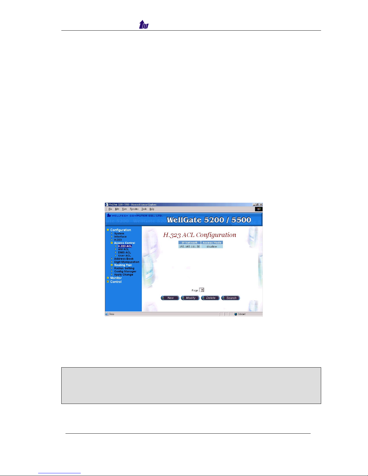
Access Control
Access Control list can be used to filter the calls forms the IP Network, DNIS,
and ANI. It must be used in call flow edit to take effect.
H.323 ACL
Start Path: Configuration→Access Control→H.323 ACL
Figure 6.5-1
Parameters:
• IP Network: IP Address or prefix used to be filtered
• Access Mode:
o Allow: the inputs IP Network are allowed for calls.
o Disallow: The inputs IP Network are disallowed for calls.
ANI ACL
Note: If in the system has both allowance and disallowance setup, the system
will check allowance first and disallowance later. If only disallowance
inputted all IP will allow to work except disallowed network. If only
allowance inputted, only those IP from allowance list will work.
WellGate 5200 User Guide - V3 - 54 -
Page 55

Welltech Computer Co., Ltd.
ANI ACL
Start Path: Configuration→Access Control→ANI ACL
Figure 6.5-2
Parameters:
• ANI: Calling party number used to filter
• Access Mode:
o Allow: the calling numbers are allowed for calls
o Disallow: The calling numbers are disallowed for calls
Note: If in the system has both allowance and disallowance setup, the system
will check allowance first and disallowance later. If only disallowance
inputted all ANI will allow to work except disallowed ANI. If only
allowance inputted, onl
y
those ANI from allowance list will work.
WellGate 5200 User Guide - V3 - 55 -
Page 56

Welltech Computer Co., Ltd.
DNIS ACL
Start Path: Configuration→Access Control→DNIS ACL
Figure 6.5-3
Parameters:
• DNIS: Called party number used for filter
• Access Mode:
o Allow: The called numbers are allowed for calls
o Disallow: The called numbers are disallowed for calls
Note: If in the system has both allowance and disallowance setup, the system
will check allowance first and disallowance later. If only disallowance
inputted all DNIS will allow to work except disallowed DNIS. If only
allowance inputted, onl
y
those DNIS from allowance list will work.
User ACL
User ACL is used when internal AAA enabled.
Start Path: Configuration→Access Control→User ACL
Figure 6.5-4
Parameters:
• User: User ID (0~9, *#)
WellGate 5200 User Guide - V3 - 56 -
Page 57

Welltech Computer Co., Ltd.
• Password: Password (0~9, *#)
• Credit Point: Allowed credit point (When credit point is used, the system will
deduct it automatically base on the rate setting.)
o Debit: Debit user
Note: 1. H.323 Authentication method must be set to “ internal AAA” to talk
effect.
2. For H.323 to PSTN WellGate5200 only can support debit user account.
New a Calling Rate:
Click Calling Rate button to add a new calling rate as figure 6.5-5.
Figure 6.5-5
Calling rate is used to convert credit point into credit time in second. For
example, you can set calling rate to 5 for “100” prefix. When a caller, which has 200
credit point, calls “100xxxx”, the max talk time, will be 200/5=40 seconds, If a
calling rate is set to “0”, it means free charge.
Search Condition:
You can search some user by User ID, Debit or Credit point as figure 6.5-6.
Figure 6.5-6
WellGate 5200 User Guide - V3 - 57 -
Page 58
Welltech Computer Co., Ltd.
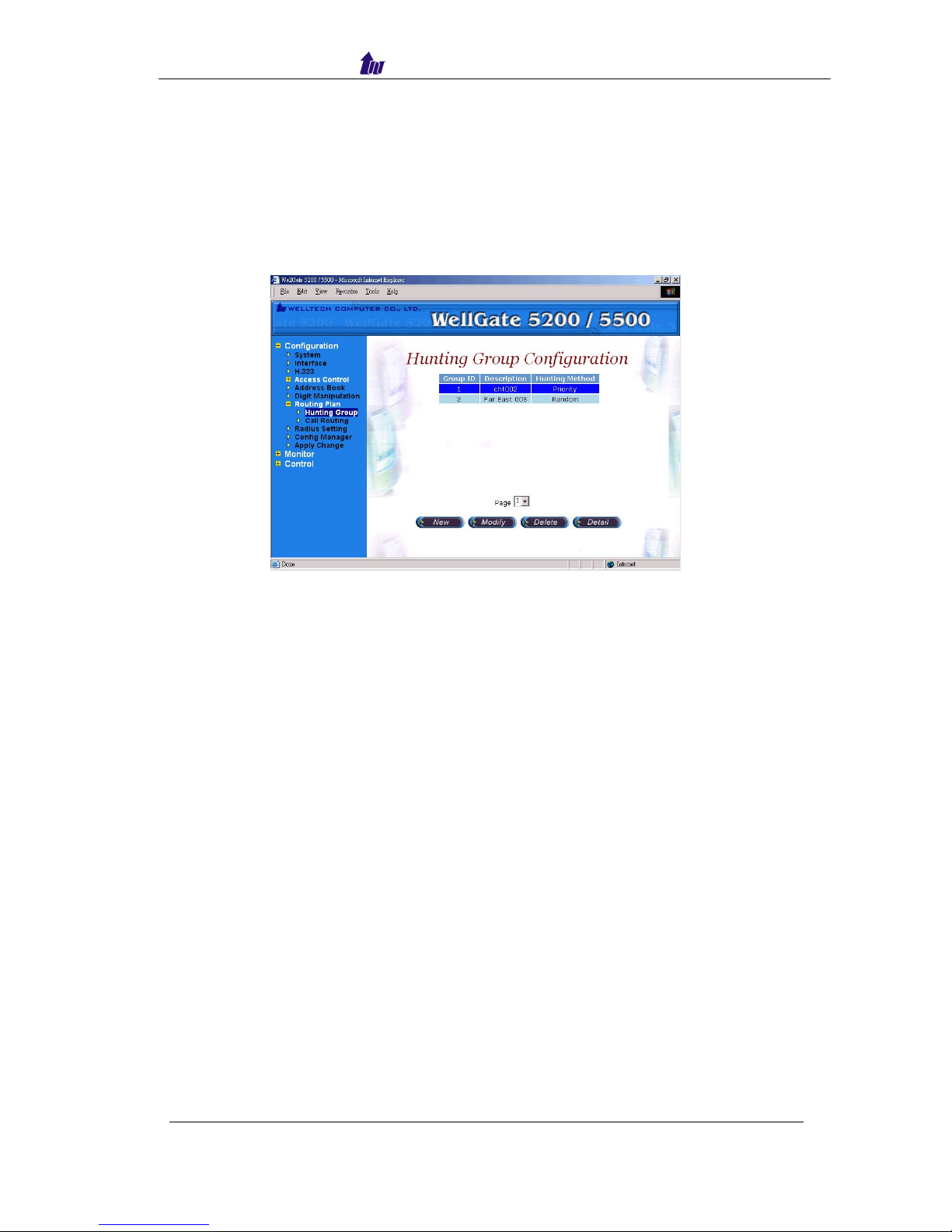
Routing Plan
The purpose of Routing Plan is to select T1/E1 trunk by your preference
when there is a call from IP side to PSTN side. It must be used in call flow edit to
take effect.
Hunting Group
Start Path: Configuration→Routing Plan→Hunting Group
Figure 6.6-1
Parameters:
• Group ID: Hunting Group ID
• Description: Description of Hunting Group
• Hunting Method: Route selection
o Random: Random select a trunk within this hunting group
o Priority: Select a trunk by priority. (Priority 1 has lowest priority; 9 has
highest priority)
WellGate 5200 User Guide - V3 - 58 -
Page 59

Welltech Computer Co., Ltd.
Call Routing
Start Path: Configuration→Routing Plan→Call Routing
Figure 6.6-2
Parameters:
• Number To Route: The dialed telephone number to be matched
• Group ID: Select the T1/E1 according to the selection of Hunting Group ID
when dialed number is matched
• Allow Use Others: To select other T1/E1 trunk when all trunk are busy at your
desired Hunting Group.
o Allowed: The call will use other T1/E1 trunks which is not belong to the
selected houting group
o Forbad: The call will be disconnected immediately
WellGate 5200 User Guide - V3 - 59 -
Page 60

Welltech Computer Co., Ltd.
Radius Setting
When you have an external RADIUS server to do the AAA (Authorization,
Authentication and Accounting), enter the correct parameter to the Radius setting. It
must be used in call flow to take effect.
Start Path: Configuration→Radius Setting
Figure 6.7-1
Parameters:
• Auth IP: Radius Authentication Server IP address (default)
• Auth Port: Radius Authentication Server Port
• Acct IP: Radius Account Server IP address
• Acct Port: Radius Account Server Port
• Backup Auth IP: Backup Radius Authentication Server IP address
• Backup Auth Port: Back Radius Authentication Server Port
• Backup Acct IP: Back Radius Account Server IP address
• Backup Acct Port: Back Radius Account Server Port
• Secret Key: The shared secret key with RADIUS Server
• Max Retry: The maximum retry times
• Response Time (sec): The maximum wait for response time from RADIUS
Server
• Auth Retry Interval (sec): The internal to resend the Authentication packet to
RADIUS Server.
• Acc Retry Interval (sec): The internal to resend the Account packet to
RADIUS Server.
• Switch Threshold: Switch to alternate RADIUS Server when failures are
occurred more than switch threshold.
WellGate 5200 User Guide - V3 - 60 -
Page 61

Welltech Computer Co., Ltd.
Apply Change
1. Some of modification needs to restart system before it is effective to system
operation. “Apply the change” shows “The change you mode need to restart the
system for apply please confirm to restart or do it later?” Click on OK button to
reboot the system.
Figure 6.8-1
2. For the modification can be changed to fly, “Apply the Change” shows “Are you
sure to apply the running system?” Click on OK button to take effecting.
Figure 6.8-2
WellGate 5200 User Guide - V3 - 61 -
Page 62

Welltech Computer Co., Ltd.
Chapter 7 System Control
System
Start path: Click Control→System
Figure 7.1-1
Parameter:
• Soft Reset: Soft Reset at WellGate5200
• Restart: Restart the WellGate5200
• Shutdown: Shutdown the WellGate5200
System Time
Please refer to section “System Time”
Network
Please refer to section “Network”
WellGate 5200 User Guide - V3 - 62 -
Page 63

Welltech Computer Co., Ltd.
SNMP
Start path: Click Control→SNMP
Figure 7.2-1
Parameter:
• Community: Community name for network manager system accessing.
• Community Rights: Giving access right to the community
Note: It takes around 1-minute to update SNMP configuration and
display successful message.
Prompt Manager
Start path: Click Control→Prompt Manager
Figure 7.3-1
WellGate 5200 User Guide - V3 - 63 -
Page 64

Welltech Computer Co., Ltd.
Note:
1. You mast has a sound card in your PC to record the voice. You need to
set Network security in order to execute this recording. Click Tool
→
Internet Option→Security→Custom Level.
2. Enable the following security to active setting:
Voice prompt editor:
- Download unsigned ActiveX control: Enable
- Initialize and script ActiveX control not marked as safe: Enable
WellGate 5200 User Guide - V3 - 64 -
Page 65

Welltech Computer Co., Ltd.
New, Record:
Step 1: Make sure you have installed microphone or other device when you want to
record, Click New and Record buttons to record as figure 7.3-2.
Figure 7.3-2
Stop, Pause, Play:
Step 2: Click Stop or Pause button to stop record, and click Play button to listen the
voice prompt as figure 7.3-3.
Figure 7.3-3
Save:
Step 3: Click Save button to saving the voice file at local path, and the screen shows
Please input the file path and file name!! (i.e. c:\irene_test.raw) as figure
7.3-4.
Figure 7.3-4
WellGate 5200 User Guide - V3 - 65 -
Page 66

Welltech Computer Co., Ltd.
Save Remote File:
Step 4: Click Save Remote File to saving the voice file at WellGate5200, and the
screen shows “please input the file path and file name!!” (i.e. 9999.raw) as
figure 7.3-5
Figure 7.3-5
Note: The file name must be “ .raw” file format.
Open Remote File:
Step 5: Click Open Remote File button to open voice file at WellGate5200 and
screen shows Voice File List as figure 7.3-6.
Figure 7.3-6
Open:
Step 6: Click Open button to open local host voice file and screen shows Choose File
as figure 7.3-7.
Figure 7.3-7
WellGate 5200 User Guide - V3 - 66 -
Page 67

Welltech Computer Co., Ltd.
Close:
Step 7: Click Close button to close the voice file as figure 7.3-8.
Figure 7.3-8
Copy:
Step 8: Select the desired voice range and click Copy button as figure 7.3-9
7.3-9
WellGate 5200 User Guide - V3 - 67 -
Page 68

Welltech Computer Co., Ltd.
Paste:
Step 9: Click Paste button to paste the voice range as figure 7.3-10.
Figure 7.3-10
Cut:
Step 10: Select the desired voice range and click Cut button as figure 7.3-11.
Figure 7.3-11
Save As: Refer the Section “Save”
Save Remote As: Refer the Section “Save Remote File”
WellGate 5200 User Guide - V3 - 68 -
Page 69

Welltech Computer Co., Ltd.
Undo:
Step 13: Click Undo button to return modification, you can see the configuration that
haven’t be changed as figure 7.3-12.
Figure 7.3-12
Redo: Refer Section “Undo”
Zoom Zoom In Zoom Out:
Step 14: Select the desired voice range click Zoom button as figure 7.3-13.
Figure 7.3-13
WellGate 5200 User Guide - V3 - 69 -
Page 70

Welltech Computer Co., Ltd.
Step 15: The screen shows the zoom out voice file range as figure 7.3-14.
Figure 7.3-14
Delete Remote file:
Step 16: Click Delete Remote file button to delete remote voice file as figure 7.3-15.
Figure 7.3-15
Call Flow Editor
Please refer section “Call Flow Editor”
Account Manager
Please refer section “Account Manager”
WellGate 5200 User Guide - V3 - 70 -
Page 71

Welltech Computer Co., Ltd.
Upgrade
Step 1: Click “Control→Upgrade” to upgrade the software as figure 7.4-1.
Figure 7.4-1
Field Description:
• File Name: Upload the software file name
• Upload: Remote Upload the software at WellGate5200
• Apply: Remote apply the upload at WellGate5200
Relogin
Please refer section “Relogin”
WellGate 5200 User Guide - V3 - 71 -
Page 72

Welltech Computer Co., Ltd.
Chapter 8 System Monitor
It provides a way to monitor the system status.
Line Summary Status
Show channel summary status.
Start Path: Monitor→Line Summary Status
Figure 8.1-1
Field Description:
• Refresh Interval (second): Refresh interval time (1, 5, 10 seconds)
• Line ID: Line ID (format: Interface: trunk: channel)
• Talk Time: Total conversation time
• Successfully calls: Total successfully calls
• Failed calls: Total failed calls
See the line detail:
Selection the line and click Detail button as figure 8.1-2.
Figure 8.1-2
Refer to line detail for field description
WellGate 5200 User Guide - V3 - 72 -
Page 73

Welltech Computer Co., Ltd.
Line Detail
Show detail channel status.
Start Path: Monitor→Line Detail
Figure 8.2-1
Field Description:
• Refresh Interval (second): Refresh interval time (1, 5, 10 seconds)
• Line ID: Line ID
• Line Status: Current time status
• Call Originate: Call originate site
• ANI String: Calling party number
• DNIS String: Called party number
• PSTN Status: PSTN site status
• H.323 Status: H.323 site status
• Escape Time: Talk time
Event Log
Show system log status.
Start Path: Configuration→Event Log
Figure 8.3-1
WellGate 5200 User Guide - V3 - 73 -
Page 74

Welltech Computer Co., Ltd.
Field Description:
• Type: Event Log type
o Information
o Warring
o Error
• Date: Event created date
• Time: Event created time
• Source: Executable program
• Category: Event type (none, welltech Sys…)
• Event ID: Event Log
Note: You can click Clear button to clear all event log.
See the detail event log:
Double click the log or select the log and click detail to see the log detail.
Figure 8.3-2
WellGate 5200 User Guide - V3 - 74 -
Page 75

Welltech Computer Co., Ltd.
Debug Info
Start Path: Click “Monitor→Debug Info”
Figure 8.4-1
Filed Description:
• Get Log: Get debug log (-1~999)
• Clear: Clear log
Ping
You can use the “Ping” to check an IP is active or not.
Start Path: Configuration→Ping
Figure 8.5-1
Field Description:
• Host IP Address: The IP address to ping
WellGate 5200 User Guide - V3 - 75 -
Page 76

Welltech Computer Co., Ltd.
Appendix 1 Call Flow Example
One Stage Dialing (Gatekeeper Mode)
Example used Components:
Start 1000
(Start)
• Next Component: 1001
CTB 1001
(Call Type Branch)
• PSTN To: 1019
• H.323 To: 1002
1002 Route for H.323 call
MakeCall 1002
(Connecting Call)
• Route Mode: PSTN
• Finish To: 1003
• Failed Other To: 1003
Disc 1003
(Disconnect)
• Reason: PSTN normal call clear
1015 Route for PSTN call
WellGate 5200 User Guide - V3 - 76 -
Page 77

Welltech Computer Co., Ltd.
MakeCall 1010 (Connecting Call)
• Route Mode: Gatekeeper Call
• Finish To: 1003
• Failed Other To: 1003
Disc 1003
(Disconnect)
Example Used Call Flow:
Make Call: 1002
Call to PSTN
Start:1000
CTB:1001
PSTN:1010
H323: 1002
1010
PSTN in
Make Call: 1010
Make Gatekeeper
call to H.323
1102
H.323 in
Disc: 1003
Disconnect
Finish to
Failed other to
Success to
WellGate 5200 User Guide - V3 - 77 -
Page 78

Welltech Computer Co., Ltd.
One Stage Dialing (Peer to Peer Mode)
Example used Components:
Start 1000
(Start)
• Next Component: 1001
CTB 1001
(Call Type Branch)
• PSTN To: 1019
• H.323 To: 1002
1002 Route for H.323 call
MakeCall 1002
(Connecting Call)
• Route Mode: PSTN
• Finish To: 1003
• Failed Other To: 1003
Disc 1003
(Disconnect)
• Reason: PSTN normal call clear
WellGate 5200 User Guide - V3 - 78 -
Page 79

Welltech Computer Co., Ltd.
1015 Route for PSTN call
MakeCall 1010
(Connecting Call)
• Route Mode: P2P Call
• Finish To: 1003
• Failed Other To: 1003
Disc 1003
(Disconnect)
Example Used Call Flow:
Make Call: 1002
Call to PSTN
Start:1000
CTB:1001
PSTN:1010
H323: 1002
1010
PSTN in
Make Call: 1010
Make Peer to Peer
call to H.323
1102
H.323 in
Disc: 1003
Disconnect
Finish to
Failed other to
Success to
WellGate 5200 User Guide - V3 - 79 -
Page 80

Welltech Computer Co., Ltd.
Two Stage Dialing (Gatekeeper Mode)
Example used Components:
Start 1000
(Start)
• Next Component: 1001
CTB 1001 (Call Type Branch)
• PSTN To: 1019
• H.323 To: 1002
1002 Route for H.323 call
MakeCall 1003
(Connecting Call)
• Route Mode: PSTN
• Finish To: 1003
• Failed Other To: 1003
Disc 1003
(Disconnect)
• Reason: PSTN normal call clear
1019 Route for PSTN call
Answer 1019
(Answer)
WellGate 5200 User Guide - V3 - 80 -
Page 81

Welltech Computer Co., Ltd.
• Next Component: 1016
SetData 1016 (Set Data)
• Assign to: DNIS
• User SysParam: no
• Value: null
PCUI 1018
(Prompt and connect user information)
• Play Type: Voice or dial tone
• Voice File: 0001.raw
• Max DTMF: 8
• Result Append To: DNIS
• End of DTMF: #
• Next Component: 1010
MakeCall 1010
(Connecting Call)
• Route Mode: Gatekeeper Call
• Finish To: 1003
• Failed Other To: 1003
Disc 1003
(Disconnect)
WellGate 5200 User Guide - V3 - 81 -
Page 82

Welltech Computer Co., Ltd.
Example Used Call Flow:
Make Call: 1003
Call to PSTN
Start:1000
CTB:1001
PSTN: 1019
H.323: 1102
PCUI:1018
Voice:
Please Input
Telephone Number
Answer:1016
(Off-Hook)
1019
PSTN in
Make Call: 1010
Make
Gatekeeper
call to H.323
1102
H.323 in
Disc: 1003
Disconnect
Finish to
Failed other to
Finish to
Failed other to
SetData:1016
Assign to: DNIS
User SysParam: No
Vaule: null
WellGate 5200 User Guide - V3 - 82 -
Page 83

Welltech Computer Co., Ltd.
Two Stage Dialing (Peer to Peer Mode)
Example used Components:
Start 1000
(Start)
• Next Component: 1001
CTB 1001 (Call Type Branch)
• PSTN To: 1019
• H.323 To: 1002
1002 Route for H.323 call
MakeCall 1003
(Connecting Call)
• Route Mode: PSTN
• Finish To: 1003
• Failed Other To: 1003
Disc 1003
(Disconnect)
• Reason: PSTN normal call clear
1019 Route for PSTN call
Answer 1019
(Answer)
WellGate 5200 User Guide - V3 - 83 -
Page 84

Welltech Computer Co., Ltd.
• Next Component: 1016
SetData 1016 (Set Data)
• Assign to: DNIS
• User SysParam: no
• Value: null
PCUI 1018
(Prompt and connect user information)
• Play Type: Voice or dial tone
• Voice File: 0001.raw
• Max DTMF: 8
• Result Append To: DNIS
• End of DTMF: #
• Next Component: 1010
MakeCall 1010
(Connecting Call)
• Route Mode: P2P Call
• Finish To: 1003
• Failed Other To: 1003
Disc 1003
(Disconnect)
WellGate 5200 User Guide - V3 - 84 -
Page 85

Welltech Computer Co., Ltd.
Example Used Call Flow:
Make Call: 1003
Call to PSTN
Start:1000
CTB:1001
PSTN: 1019
H.323: 1102
PCUI:1018
Voice:
Please Input
Telephone Number
Answer:1016
(Off-Hook)
1019
PSTN in
Make Call: 1010
Make
P2P Call
call to H.323
1102
H.323 in
Disc: 1003
Disconnect
Finish to
Failed other to
Finish to
Failed other to
SetData:1016
Assign to: DNIS
User SysParam: No
Vaule: null
WellGate 5200 User Guide - V3 - 85 -
Page 86

Welltech Computer Co., Ltd.
Two Stage Dialing with AAA (Gatekeeper Mode)
Example used Components:
Start 1000
(Start)
• Next Component: 1001
CTB 1001
(Call Type Branch)
• PSTN To: 1022
• H.323 To: 1003
1003 Route for H.323 call
MakeCall 1003
(Connecting Call)
• Route Mode: PSTN
• Finish To: 1012
• Failed Other To: 1012
Disc 1012
(Disconnect)
• Reason: PSTN normal call clear
WellGate 5200 User Guide - V3 - 86 -
Page 87

Welltech Computer Co., Ltd.
1002 Route for PSTN call
Answer 1002
(Answer)
• Next Component: 1004
SetData 1004 (Set Data)
• Assign to: DNIS
• User SysParam: no
• Value: Null
• Next Component: 1005
PCUI 1005
(Prompt and connect user information)
• Play Type: Voice or dial tone
• Voice File: 0002.raw
• Max DTMF: 8
• Result Append To: User ID
• End of DTMF: #
• Next Component: 1006
PCUI 1006
(Prompt and connect user information)
• Play Type: Voice or dial tone
• Voice File: 0003.raw
• Max DTMF: 8
• Result Append To: Password
• End of DTMF: #
• Next Component: 1007
PCUI 1007 (Prompt and connect user information)
• Play Type: Voice or dial tone
• Voice File: 0001.raw
• Max DTMF: 8
• Result Append To: DNIS
• End of DTMF: #
• Next Component: 1008
AAA 1008
(Authentication Authorization Accounting)
• Success to: 1009
• Failed to: 1010
PD 1009 (Play Duration)
• Voice File: 0004.raw
• Language: English
WellGate 5200 User Guide - V3 - 87 -
Page 88

Welltech Computer Co., Ltd.
• Interrupted: No
• Next Component: 1013
PA 1010
(Play Announcement)
• Dynamic Play: Disable
• Voice File: 0005.raw
• Language: English
• Interrupted: No
• Next Component: 1011
Disc 1011
(Disconnect)
MakeCall 1013
(Connecting Call)
• Route Mode: Gatekeeper Call
• Finish To: 1012
• Failed Other To: 1012
Quit 1012
(Quit)
WellGate 5200 User Guide - V3 - 88 -
Page 89

Welltech Computer Co., Ltd.
Example Used Call Flow:
Make Call: 1003
Call to PSTN
Start:1000
CTB:1001
PSTN: 1002
H.323: 1003
PCUI:1006
Voice:
Please enter your
password
Answer:1016
(Off-Hook)
1021
PSTN in
Make Call: 1013
Make Gatekeeper
call to H.323
1102
H.323 in
Quit: 1012
Disconnect
Success or failed other to
Success or failed to
PCUI:1005
Voice:
Please enter User ID
PCUI:1007
Voice:
Please enter the
destination
AAA:1008
Success: 1025
Failed: 1010
PA:1010
Voice: Please check
and try later
PD:1009
Voice: You have ....
The remaining time is
Play duration: 3 minutes and
56 seconds
Success to
Failed to
Set Data:1004
DNIS: Null
Disc: 1011
Voice: User ID or
password is invalid,
please try later.
WellGate 5200 User Guide - V3 - 89 -
Page 90

Welltech Computer Co., Ltd.
Appendix 2 Java plug-in Installation
You need to install Java Plug-in before using call flow editor, prompt manager and
upgrade. Please confirm you JRE version is 1.3.1_02 or above if your PC has already
installed Java.
After downloaded the java runtime version (1.3.1 or later) from Sun, you just
follow the wizard to install the Java runtime. When you see the display shows “Select
Browsers”, do not select any option item, press Next button to continue.
You also need to set newer versions of stored pages. Click Tool
→
Internet Option
→
General→Setting.
After success, restart your browser to take effect.
WellGate 5200 User Guide - V3 - 90 -
Page 91

Welltech Computer Co., Ltd.
Appendix 3 Retrieve CDR Information
Retrieve method:
1. Ftp IP addess
2. Input user/password
3. Cd CDR
4. Get STRTxxxxxxxx.log or STOPxxxxxxxxx.log
5. Close
Note: Only “root” and “admin” can be used for retrieving CDR via ftp.
Billing Start CDR:
• File name: STRTyyyymmdd.log
• Field delimit: ,
• Field description:
NAS-IP-Address : H.323 gateway IP address
NAS-Port-Type : (Network Access Server Port Type) Asynchronous
User-Name : User ID
Calling-Station-Id : Calling station number
Acct-Status-Type : Message type (0: start)
Service-Type : 1: login
Gateway-Name : H.323 gateway aliases
Conf-ID : GUID
Call-Type : Telephony or VOIP
Call-Originate : originate or answer
Setup-Time : Call initiate time (UTC time)
Acct-Session-Id : N/A
Acct-Delay-Time : N/A
Billing Stop CDR:
• File name: STOPyyyymmdd.log
• Field delimit: ,
• Field description:
NAS-IP-Address : H.323 gateway IP address
NAS-Port-Type : (Network Access Server Port Type) Asynchronous
User-Name : User ID
Called-Station-Id : Called station number
Calling-Station-Id : Calling station number
Acct-Status-Type : Message type (1: Stop)
Service-Type : 1: login
Gateway-Name : H.323 gateway aliases
Conf-ID : GUID
Call-Type : Telephony or VOIP
Call-Originate : originate or answer
Setup-Time : Setup Time (UTC time)
Connect-Time : Connect Time (UTC time)
WellGate 5200 User Guide - V3 - 91 -
Page 92

Welltech Computer Co., Ltd.
Disconnect-Time : Disconnect Time (UTC time)
Disconnect-Cause : Disconnect cause code
Voice-Quality : Voice Quality
Gateway-ID : Remote gateway IP address
Acct-Session-Id : N/A
Acct-Input-Octets : N/A
Acct-Output-Octets : N/A
Acct-Input-Packets : N/A
Acct-Output-Packets : N/A
Acct-Session-Time : N/A
Acct-Delay-Time : N/A
WellGate 5200 User Guide - V3 - 92 -
Page 93

Welltech Computer Co., Ltd.
Appendix 4 Quick Start Check List
Host Network:
IP Address: _____. _____. _____. _____
Sub-Mask: _____. _____. _____. _____
Default-Gateway:_____. _____. _____. _____
Interface Network:
IP Address: _____. _____. _____. _____
Sub-Mask: _____. _____. _____. _____
Default-Gateway: _____. _____. _____. _____
H.323 Configuration:
Register to Gatekeeper Peer To Peer
GK IP Address: _____. _____. _____. _____ Refer to User Guide-Phone
GK RAS Port: ______ Book setting
H.245 tunneling: Enable Disable
Fast Connect:
Enable Fast Start Early H.245 Disable
Separate H.245 after Fast Start: Ye s No
Fast Start Enabled Codec:
G.711 a-law
G.711 u-law
G.729
G.729 A/B
G.723.1 (5.3K)
G.723.1 (6.3A)
Codec Select Priority:
__ G.711 a-law
__ G.711 u-law
__ G.729
__ G.729 A/B
__ G.723.1 (5.3K)
__ G.723.1 (6.3A)
PSTN Interface:
PCM encoding: A-law Mu-law
PCM Idle Pattern:
Default (-1):
0x55 A-law 0xff u-law specified: ______
Clock Source: External Internal
E1
Framing Method:
Automatic CRC4 or Double Frame selection
Double Frame Format
CRC4 multi-frame
CRC4 extend multi-frame
Line Code: HDB3 AMI
WellGate 5200 User Guide - V3 - 93 -
Page 94

Welltech Computer Co., Ltd.
ISDN/PRI:
Termination Site:
Network User site
Variance:
Euro ISDN
Australia ISDN
Hong Kong ISDN
Korea ISDN
CAS:
CAS Idle ABCD signal: Default (-1): specified: ______
E1 MFC R2
E1 CAS R2
Variance:
E1 R2D MODIFIED
E1 R2 MF Aregntina 7digits no ANI
E1 R2 MF Aregntina 7digits with ANI
E1 R2 MF Bolivia 7digits no ANI
E1 R2 MF Bolivia 7digits with ANI
E1 R2 MF Brazil 7digits no ANI
E1 R2 MF Brazil 7digits with ANI
E1 R2 MF Chile 7digits no ANI
E1 R2 MF Chile 7digits with ANI
E1 R2 MF China 7digits no ANI
E1 R2 MF China 7digits with ANI
E1 R2 MF Czech-Republic 7digits no ANI
E1 R2 MF Czech-Republic 7digits with ANI
E1 R2 MF Egypt no ANI
E1 R2 MF Egypt with ANI
E1 R2 MF India 10Digits no ANI
E1 R2 MF India 10Digits with ANI
E1 R2 MF Indonesia 7Digits no ANI
E1 R2 MF Indonesia 7Digits with ANI
E1 R2 MF Israel(Bezeq) no ANI
E1 R2 MF Israel(Bezeq) with ANI
E1 R2 MF ITU 7digits no ANI
E1 R2 MF ITU 7digits with ANI
E1 R2 MF KOREA 7digits no ANI
E1 R2 MF KOREA 7digits with ANI
E1 R2 MF Malaysia 7Digits no ANI
E1 R2 MF Malaysia 7Digits with ANI
E1 R2 MF Mexico 7digits no ANI
E1 R2 MF Mexico 7digits with ANI
E1 R2 MF Philippines no ANI
E1 R2 MF Philippines with ANI
E1 R2 MF Thailand 7Digits no ANI
E1 R2 MF Thailand 7Digits with ANI
E1 R2 MF Uruguay 7Digits no ANI
E1 R2 MF Uruguay 7Digits with ANI
E1 R2 MF Venezuela 7Digits no ANI
E1 R2 MF Venezuela 7Digits with ANI
WellGate 5200 User Guide - V3 - 94 -
Page 95

Welltech Computer Co., Ltd.
T1
Framing Method:
super frame
4-frame multi-frame
12 frame multi-frame (D4)
extend super frame without CRC6
extend super frame with CRC6
72-Frame Multi-Frame
Line Code: AMI B8ZS
ISDN/PRI:
Termination Site: Network User site
Variance:
NI2 ISDN
5ESS 9 ISDN
5ESS 10 ISDN
DMS100 ISDN
NTT ISDN (INS1500)
CAS:
CAS Idle ABCD signal: Default (-1): specified: ______
T1 CAS
Variance:
T1 E&M BellCore Feature Group D Wink Start
T1 E&M Delay Start
T1 E&M Feature Group A Immediate Start
T1 E&M Feature Group B Wink Start
T1 E&M Feature Group D Wink Start(ANI B4 ADDR)
T1 E&M Feature Group D Wink Start
T1 E&M Immediate Start
T1 E&M Wink Start
T1 GroundStart FXO
T1 GroundStart FXS
T1 LoopStart FXO
T1 LoopStart FXS
WellGate 5200 User Guide - V3 - 95 -
Page 96

Welltech Computer Co., Ltd.
Appendix 5 Interface LED Description
Interface Real Panel:
Ethernet LED:
Trunk LED:
Trunk RJ48 Wiring:
WellGate 5200 User Guide - V3 - 96 -
Page 97

Welltech Computer Co., Ltd.
Appendix 6 Build-in Voice Prompt Index
File Name Description
0001.raw Please enter the destination
0002.raw Please enter your user ID
0003.raw Please enter your password
0004.raw You have
0005.raw User ID or password is invalid. Please try later.
WellGate 5200 User Guide - V3 - 97 -
Page 98

Welltech Computer Co., Ltd.
Quick Function Reference
A
Access Control……………………………………………………………… 54
Account Manager…………………………………………………………… 12
Confirm Password……………………………………………………….. 13
Description……………………………………………………………….. 13
Password…………………………………………………………………. 13
User ID..………………………………………………………………….. 13
User Role………………………………………………………………… 13
ANI ACL……………………………………………………………………. 55
Access Mode…………………………………………………………….. 55
ANI………………………………………………………………………. 55
Apply Change………………………………………………………………. 61
C
Call Flow Editor……………………………………………………………. 27
AAA…………………………………………………………………….. 28
Answer…………………………………………………………………… 28
Branch……………………………………………………………………. 28
CDV……………………………………………………………………… 29
CIB………………………………………………………………………. 29
CIV……………………………………………………………………… 30
CTB……………………………………………………………………… 30
Cut Rule………………………………………………………………… 30
Disc……………………………………………………………………… 31
DM………………………………………………………………………. 31
MakeCall………………………………………………………………… 31
PA……………………………………………………………………….. 32
PCUI…………………………………………………………………….. 33
PD……………………………………………………………………….. 33
PSTN L.H……………………………………………………………….. 33
Set Data………………………………………………………………….. 34
Start………………………………………………………………………. 34
Quit………………………………………………………………………. 34
Call Routing…………………………………………………………………. 59
Allow User Other………………………………………………………… 59
Group ID…………………………………………………………………. 59
Number To Route………………………………………………………… 59
Config Manager…………………………………………………………….. 37
D
Debug Info……………………………………………………………………75
DNIS ACL…………………………………………………………………… 56
WellGate 5200 User Guide - V3 - 98 -
Page 99

Welltech Computer Co., Ltd.
Access Mode…………………………………………………………….. 56
DNIS……………………………………………………………………. 56
E
Event Log…………………………………………………………………… 73
Category………………………………………………………………….. 74
Date.……………………………………………………………………… 74
Time……………………………………………………………………… 74
Type……………………………………………………………………… 74
Source……………………………………………………………………. 74
H
Hunting Group……………………………………………………………… 58
Description……………………………………………………………….. 58
Group ID…………………………………………………………………. 58
Hunting Method………………………………………………………….. 58
H.323 Configuration………………………………………………………... 52
Codec Priority…………………………………………………………… 53
Connect Timeout (Q.931) (sec) ………………………………………… 52
DTMF Relay…………………………………………………………….. 53
Ext. AAA Failure Opt…………………………………………………… 52
E.164 Tel………………………………………………………………… 52
Fast Connect Mode……………………………………………………… 53
Fax Transport……………………………………………………………. 53
Fax Rdepth………………………………………………………………. 54
FS Enable………………………………………………………………… 53
Gatekeeper IP……………………………………………………………. 52
Gatekeeper RAS…………………………………………………………. 52
G.711 Psize………………………………………………………………. 54
G.723 Psize……………………………………………………………… 54
G.729 Psize……………………………………………………………… 54
H.245 Option……………………………………………………………. 54
H.245 Tunneling………………………………………………………… 53
H.450 Service…………………………………………………………… 54
Inbound DM Group……………………………………………………… 53
Max Call………………………………………………………………… 53
Max Channel……………………………………………………………. 53
Outbound DM Group…………………………………………………… 53
Q.931 Port……………………………………………………………….. 53
RAS Port…………………………………………………………………. 53
RAS Multicast IP………………………………………………………… 53
RAS Multicast Port……………………………………………………… 53
Register H.323 ID…………………………………………………………52
Register Time To Live (sec) ………………………………………………52
Response Timeout (Q.931) (sec) …………………………………………52
Register to Gatekeeper…………………………………………………… 52
T.38 ECM Mode…………………………………………………………. 54
H.323 ACL………………………………………………………………….. 54
Access Mode…………………………………………………………….. 54
IP Network………………………………………………………………. 54
WellGate 5200 User Guide - V3 - 99 -
Page 100

Welltech Computer Co., Ltd.
I
Interface…………………………………………………………………….. 47
CAS Idle Pattern………………………………………………………… 48
Card Slot………………………………………………………………… 48
Clock Source…………………………………………………………….. 47
Default Gateway…………………………………………………………..47
Description………………………………………………………………. 47
EC Tail Length…………………………………………………………… 49
Interface ID………………………………………………………………. 47
Interface Type……………………………………………………………. 47
IP Address……………………………………………………………….. 47
IP Precedence…………………………………………………………….. 48
IP TOS…………………………………………………………………… 48
Jitter Min Delay………………………………………………………….. 48
Jitter Opt Factor………………………………………………………….. 49
License Key……………………………………………………………… 47
PCM Idle Pattern………………………………………………………… 48
PCM Type……………………………………………………………….. 47
Serial No………………………………………………………………… 47
Silence Compress………………………………………………………… 49
Subnet Mask…………………………………………………………….. 47
UDP Port Base…………………………………………………………… 48
L
Line Detail………………………………………………………………….. 73
ANI String……………………………………………………………….. 73
Call Originate……………………………………………………………. 73
DNIS String……………………………………………………………… 73
Escape Time……………………………………………………………… 73
H.323 Status……………………………………………………………… 73
Line ID…………………………………………………………………… 73
Line Status……………………………………………………………….. 73
PSTN Status……………………………………………………………... 73
Line Summary……………………………………………………………… 72
Failed Calls……………………………………………………………… 72
Line ID………………………………………………………………….. 72
Successful Calls………………………………………………………… 72
Talk Time……………………………………………………………….. 72
M
Monitor……………………………………………………………………... 72
N
Network……………………………………………………………………. 9
P
Ping………………………………………………………………………… 75
Prompt Manager………………………………………………………….. 63
Close……………………………………………………………………. 67
Copy……………………………………………………………………. 67
WellGate 5200 User Guide - V3 - 100 -
 Loading...