

Page 1

WellGate 3511N Technical Manual V.100
Welltech
Wi-Fi VoIP Gateway
(WellGate 3511N)
Technical Manaul
Revision information
Version Date Description
EN-V1.00 Jun-18-2009 1st English version
Copyright © 2007 Welltech Computer Co., Ltd. All right reserved.
Page 2

WellGate 3512 Technical Manual V.103
TABLE OF CONTENT
CHAPTER 1 OVERVIEW OF THE WG3511N.................................................5
Front View............................................................................................................................................... 8
Back View................................................................................................................................................ 9
Specification of connector......................................................................................................................9
Call Features......................................................................................................................................... 10
Direct IP Call....................................................................................................................... 10
Proxy Call............................................................................................................................ 10
Call Waiting.........................................................................................................................10
Three-way Conference ........................................................................................................10
Call Transfer (Blind Transfer) .............................................................................................10
CHAPTER 2 CONFIGURING THE WG3511N THROUGH VOICE PROMPT
AND PHONE SET .........................................................................................12
CHAPTER 3 CONFIGURING THE WG3511N THROUGH WEB PAGES.....14
Step 1. Power on the WG3511N...........................................................................................................14
Step 2. Check the LEDs........................................................................................................................ 14
Step 3. Connect PC with one of LAN port.......................................................................................... 14
Step 4. Browse the Default IP Address of WG3511N and enter the web interface main screen.....14
Step 5. Start to configure...................................................................................................................... 15
Setup Wizard.........................................................................................................................................16
Operation Mode:..................................................................................................................16
Time Zone Setting...............................................................................................................17
LAN Interface Setup............................................................................................................18
WAN Interface Setup........................................................................................................... 19
Wireless Basic Settings .......................................................................................................22
Wireless Security Setup....................................................................................................... 23
Operation Mode.................................................................................................................................... 28
Page 3

WellGate 3512 Technical Manual V.103
Wireless .................................................................................................................................................29
Basic Settings ......................................................................................................................29
Advanced Setting ................................................................................................................31
Security................................................................................................................................ 33
Access Control ....................................................................................................................36
WDS Settings ......................................................................................................................36
Site Survey ..........................................................................................................................37
WPS..................................................................................................................................... 38
TCP/IP Settings.....................................................................................................................................39
LAN Interface......................................................................................................................39
WAN Interface.....................................................................................................................40
Firewall.................................................................................................................................................. 44
Port Filtering........................................................................................................................44
IP Filtering........................................................................................................................... 45
MAC Filtering ..................................................................................................................... 46
URL Filtering ......................................................................................................................47
Port Forwarding................................................................................................................... 48
DMZ.................................................................................................................................... 49
VoIP Settings......................................................................................................................................... 50
Home User Wizard ..............................................................................................................50
FXS......................................................................................................................................61
FXO.....................................................................................................................................69
Tone ..................................................................................................................................... 76
Ring ..................................................................................................................................... 80
Other.................................................................................................................................... 81
Config.................................................................................................................................. 83
Management..........................................................................................................................................89
Status ................................................................................................................................... 89
Statistics...............................................................................................................................90
DDNS.................................................................................................................................. 90
Time Zone Setting...............................................................................................................91
Denial-of-Service ................................................................................................................93
Log ......................................................................................................................................93
Upgrade Firmware...............................................................................................................94
Save/Reload Settings...........................................................................................................95
Page 4

WellGate 3512 Technical Manual V.103
Copyright © 2007 Welltech Computer Co., Ltd. All right reserved.
4
Password..............................................................................................................................96
Logout.................................................................................................................................................... 97
CHAPTER 4 WIRELESS OPERATION MODES........................................... 98
Access Point...........................................................................................................................................98
Access point with NAT........................................................................................................ 98
Access point With Bridge mode (Without NAT)................................................................. 99
Client (Infrastructure) .......................................................................................................................100
Client (Ad-hoc)....................................................................................................................................101
P2P Bridge...........................................................................................................................................102
WDS Repeater ....................................................................................................................................103
Universal Repeater ............................................................................................................................. 105
WISP.................................................................................................................................................... 106
WISP + Universal Repeater ............................................................................................................... 107
Page 5

WellGate 3511N Technical Manual EN-V100
Copyright © 2007 Welltech Computer Co., Ltd. All right reserved.
5
Chapter 1 Overview of the WG3511N
WellGate 3511N is a one-port FXS + one PSTN wireless gateway, which supports RFC3261 SIP protocol.
Telephone will switch to PSTN port automatically under power failure. User can also select to dial out through
PSTN line manually. WG-3511N complies with wireless protocol 802.11 b/g, and can operate as Access Point
or Client. Built-in four LAN ports and NAT function allows other devices to access network more easily.
Benefits
Easy access to IP from phone set or PBX
Cost Saving - Telephone call from VPN or public Internet
Follows the existing telephone call dial plan
Easy interface to ADSL/Cable Modem or Leased line equipment
Easy to integrate with all kinds of IP-PBXs
Physical interface
RJ-45
¾ WAN X 1 for connecting to HUB or ATU-R directly
¾ LAN X 4 for PC or other devices
RJ-11
¾ Phone X 2 for regular phone connection
¾ PSTN X 1 for Dialing and Receiving PSTN call.
Power: Input AC 100V~240V Output DC12V
LED Indicator: Power, WLAN, WAN, LAN, FXS, PSTN
Voice Feature
Codec: G.711u/A-Law, G.729A , G.726, GSM-FR
VAD/CNG
Adaptive Jitter Buffer
Line Echo Cancellor
FAX/Modem tone detection and pass through
DTMF: Inband, RFC-2833, SIP Info
Network
Auto MDI/MDI-X
802.11 b/g Access Point, WiFi compliant
¾ 802.1x, WEP, WPA TKIP and WPA2 AES/Mixed
¾ mode for PSK and TLS (Radius)
¾ 802.11f (IAPP)
¾ Wireless Auto-channel selection
¾ Wireless access control by MAC address (deny or accept)
Page 6

WellGate 3511N Technical Manual EN-V100
Copyright © 2007 Welltech Computer Co., Ltd. All right reserved.
6
802.11b/g client mode
WISP Mode
WDS and Universal Repeater Mode
802.1d with spanning tree protocol
NAT/NAPT
Firewall
Virtual DMZ
ALG for:FTP, SIP, VPN pass-through with multiple sessions (IPSEC, L2TP)
DHCP client and server
Up to 98MB throughput at Bridge Mode
Qos: 802.1Q (VLAN)
Bandwidth Control
PPPoE
UPnP IGD
STUN
DDNS and NTP client
QOS - DSCP class0-7 and EF
URL Filtering and DoS (Deny of Service)
DNS relay
Telephony Features
Caller ID: TypeI/II DTMF, FSK
Flash Hook Timer Configuration
Gain Adjustments
PSTN Bypass: Power Failure, Manually
Call Waiting
Call Hold
Blind Transfer
Call Forward
3-way Conference
10 Speed Dials
T.38 FAX
Dimension
17.5 x 12.5 x 3.2 cm
Protocol
SIP RFC3261
TCP/UDP/IP/ICMP/ARP
Management
Page 7

WellGate 3511N Technical Manual EN-V100
Copyright © 2007 Welltech Computer Co., Ltd. All right reserved.
7
System log
Display real-time information for system setting, statistics, and associated wireless client
status.
User name/password authentication for web server login and logout
Web-based configuration and management interface
Firmware update through web
Configuration backup/restore to/from a file. Reset configuration to factory default
IVR-Configuration by phone keys with Interactive Voice Prompts
Certification
CE, FCC
Page 8
WellGate 3511N Technical Manual EN-V100
Copyright © 2007 Welltech Computer Co., Ltd. All right reserved.
8
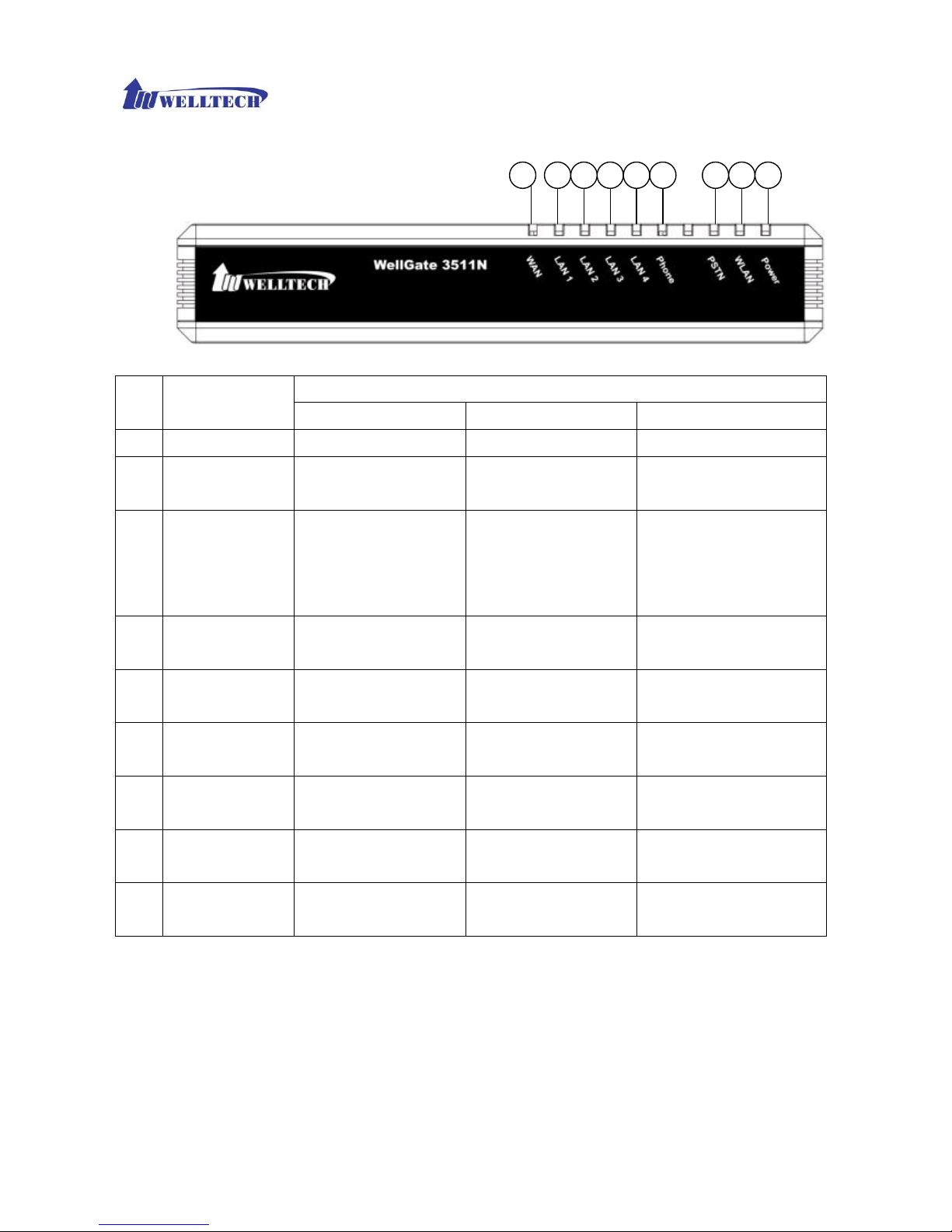
Front View
Status
LED Indicator
Light On Light Off Light Flashing
1 Power
power on power off N/A
2 WLAN
N/A Wifi is OFF or failed WLAN is transmitting or
receiving data.
3 PSTN
PSTN (FXO) is
registered to Proxy or
PSTN is not set to
register
PSTN (FXO) line is
failed to register to
Proxy
PSTN has incoming call or
PSTN line is in use.
4 Phone
Phone (FXS) is
registered to Proxy
Phone (FXS) is failed to
register to Proxy
Phone has incoming call
or Phone is in use.
5 LAN 4
Network is connected Network is not
connected
Network is transmitting or
receiving data.
6 LAN 3
Network is connected Network is not
connected
Network is transmitting or
receiving data.
7 LAN 2
Network is connected Network is not
connected
Network is transmitting or
receiving data.
8 LAN 1
Network is connected Network is not
connected
Network is transmitting or
receiving data.
9 WAN
Network is connected Network is not
connected
Network is transmitting or
receiving data.
9 6 5 4 3 2 18 7
Page 9
WellGate 3511N Technical Manual EN-V100
Copyright © 2007 Welltech Computer Co., Ltd. All right reserved.
9
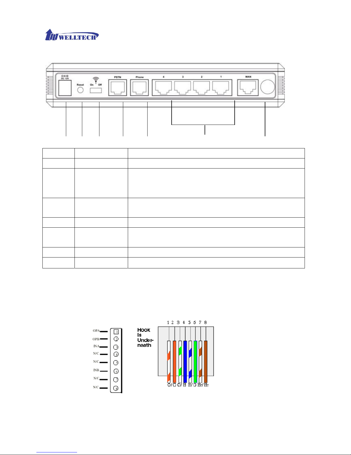
Back View
A C D E F G B
Port/ Button Functions
A 12V DC
Input AC 100V~120V. Output DC12V.
B Reset
Press Reset key over 5 seconds, WG3511N will reboot and all
configurations will restore to default values. If user press Reset key for
3-5 seconds, WG3511N will only reboot, but not return to default values.
C Wifi switch
Wifi Switch on/off. When it is set to OFF, wifi will be disabled. If it is set to
ON, wifi could be ON or based on the wifi activation scheduling.
D PSTN
RJ-11 interface for connecting the extension line of PABX or PSTN Line.
E Phone
RJ-11 interface for connecting the analog phone sets or trunk line of
PABX.
F LAN 4 3 2 1
10/100 Base-T; RJ-45 socket, complied with ETHERNET 10/100base-T.
G WAN
10/100 Base-T; RJ-45 socket, complied with ETHERNET 10/100base-T.
Specification of connector
Ethernet Port
Ethernet port is for connecting WG3511N to network, transmit rate supports 10/100 Base-T.
Page 10

WellGate 3511N Technical Manual EN-V100
Copyright © 2007 Welltech Computer Co., Ltd. All right reserved.
10
Call Features
Direct IP Call
User can dial out call with IP address directly.
¾ Dial IP: ex. To dial out IP 192.168.1.1 via phone set need to press 192*168*1*1#. “#” means
to dial out immediately, if user doesn’t follow by “#” sign, WG3512 will dial out after “auto dial
time”.
¾ Dial IP and port: To dial out IP 192.168.1.1 and port 5061 via phone set need to press
192*168*1*1**5061#. “#” means to dial out immediately, if user doesn’t follow by “#” sign,
WG3511N will dial out after “auto dial time”.
Proxy Call
User can dial out phone number if WG3511N registered to Proxy successfully. Ex. To dial out
phone number 100 via phone set need to press 100#. “#” means to dial out immediately, if user
doesn’t follow by “#” sign, WG3511N will dial out after “auto dial time”.
Note:
If WG3511N registered on Proxy successfully, the LED of Phone will light up, and on web page—VoIP
Settings—Phone—SIP Proxy—Register Status will display registered.
Call Waiting
When Phone is in communication, WG3511N can receive another incoming call.
¾ Call Scenario:
1) Phone is in communication with A. B calls in Phone . From Phone will hear call waiting
tone.
2) Phone press flash hook, A will be put on hold, and Phone will enter communication with B.
3) Phone press flash hook again can return to communicate with A, and B will be put on
hold.
Three-way Conference
WG3511N supports three-way conference.
¾ Call Scenario:
1) Phone is in communication with A.
2) Phone press flash hook will hear dial tone.
3) Dial out to B, after talk with B, press flash hook again will get into conference call with A
and B.
Call Transfer (Blind Transfer)
WG3511N supports Blind Transfer only.
¾ Call Scenario:
1) Phone is in communication with A.
2) Phone press “*1”
3) B will be put on hold, and Phone will hear Dial tone.
4) Phone dial to B, both Phone and A will hear ring back tone.
Page 11

WellGate 3511N Technical Manual EN-V100
Copyright © 2007 Welltech Computer Co., Ltd. All right reserved.
11
5) B picks up, B and C in communication, A hear busy tone and disconnect.
Page 12

WellGate 3511N Technical Manual EN-V100
Copyright © 2007 Welltech Computer Co., Ltd. All right reserved.
12
Chapter 2 Configuring the WG3511N through Voice Prompt and Phone
set
Please connect one analog phone set with Phone port of WG3511N, and then input specific keys as below to
get some information or make brief configurations.
Category Function Input Key Example
DHCP client for WAN
#111 #111#
Set Fixed IP for WAN
#112
#112192*168*0*100#
set IP as 192.168.0.100
Set Netmask for WAN
#113
#113255*255*255*0#
set netmask as 255.255.255.0
Set Gateway for WAN
#114
#114192*168*1*254#
set gateway as 192.168.1.254
Set DNS
#115
#115168*95*1*1#
set DNS ad 168.95.1.1
Set Network
Settings
Set Fixed IP for LAN
#116
#116192*168*1*254#
set IP as 192.168.1.254
Voice LAN IP address
#120 #120#
Voice IP type
#121 #121#
Voice SIP register ID
#122 #122#
Voice netmask
#123 #123#
Voice gateway
#124 #124#
Voice DNS
#125
#125#
Voice WAN IP address
#126 #126#
Voice Network
Settings
Voice firmware version
#128 #128#
Page 13

WellGate 3511N Technical Manual EN-V100
Copyright © 2007 Welltech Computer Co., Ltd. All right reserved.
13
Set first priority codec
#130 + first priority codec
#13001#
Set 711 u-law to be first
priority codec.
Codec Number:
01: G.711 u-law
02: G.711 a-law
03: G.729
04: G.723 6.3k
05: G.723 5.3k
06: G.726-16
07: G.726-24
08: G.726-32
09: G.726-40
Handset gain
#131
#13109#
Set handset gain as 9
(Range of gain: 1~10)
Handset volume
#132
#13209#
Set handset volume as 9
(Range of gain: 1~10)
Enable call waiting
#138 #138#
Disable call waiting
#139 #139#
Forward setting
#140 + Forward type
+Forwarded Phone Number
#1401101#Immediate forward
to 101Forward Type:1:
Immediate forward2. Busy
forward3. No answer forward
VoIP Settings
Disable forward setting
#141 #141#
Apply Setting
#195 #195#
Others
Reset to default
#198 #198#
Page 14
WellGate 3511N Technical Manual EN-V100
Copyright © 2007 Welltech Computer Co., Ltd. All right reserved.
14
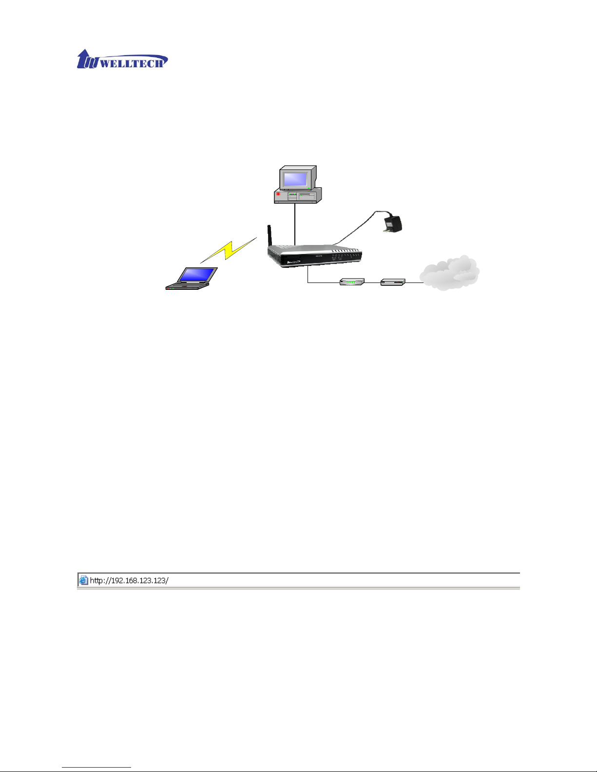
Chapter 3 Configuring the WG3511N through Web Pages
The HTTP web management interface provides user an easy way to configure WG3511N.
Power Adapter
PC LAN
IP address: DHCP
PC WLAN
IP address: DHCP
ESSID: WiFi_AP
Channel: 11
Encryption: disabled
WG 3511N
WAN default IP address: DHCP
LAN default IP address: 192.168.123.123
SSID: WiFi_AP
Channel: 11
Encryption: disabled
SOHO Router
Internet
ADSL/ Cable
Modem
LAN
WAN
Step 1. Power on the WG3511N
Step 2. Check the LEDs
After power on, the [Power] and [PSTN] LEDs should be on; [WLAN] LED should be blinking.
Step 3. Connect PC with one of LAN port
Please connect PC with one of the LAN port on WG3511N and set PC as DHCP mode. PC will get one
dynamic IP from WG3511N, such as 192.168.123.1.
Step 4. Browse the Default IP Address of WG3511N and enter the web interface main
screen
Please enter IP address of WG3511N in web browser. The default IP address of WG3511N is
192.168.123.123. and default user name and password is root/root, and the user can see web interface main
screen as below.
Page 15

WellGate 3511N Technical Manual EN-V100
Copyright © 2007 Welltech Computer Co., Ltd. All right reserved.
15
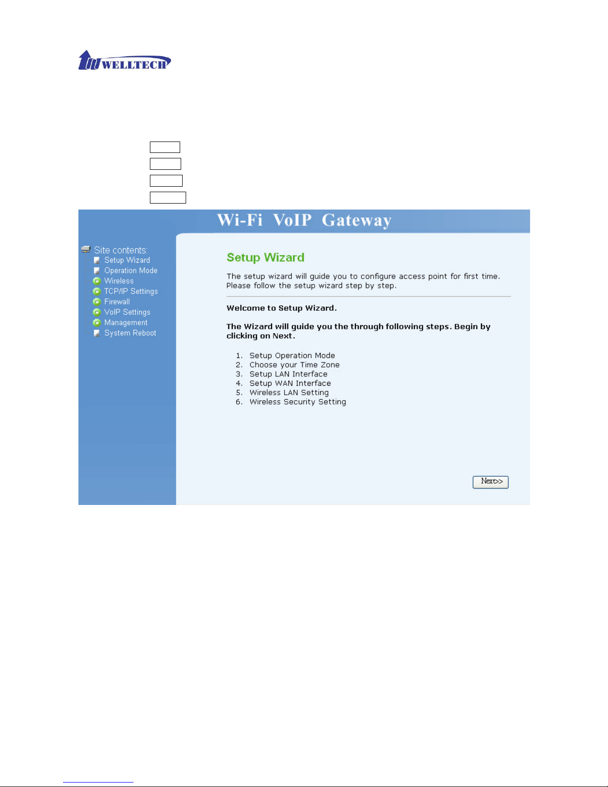
Step 5. Start to configure
After enter web management interface, user can see 8 main items.
1. Setup Wizard: User can follow steps in wizard to make first-time initial configuration.
2. Operation Mode: User can setup different modes to LAN and WLAN interface for NAT and bridging
function.
3. Wireless: User can set all wireless related parameters here.
4. TCP/IP: User can set LAN and WAN related configurations here.
5. Firewall: User can set firewall function of WG3511N here.
6. VoIP Setting: User can set VoIP related parameters here.
7. Management: User can check information or manage WG3511N here.
8. System Reboot: User can remote reboot WG3511N here.
Button Definition:
1. Apply Changes: After change or input any parameter, press this button will save data into WG3511N.
2. Reset: Press this button will clean data input by user and restore to original data.
Page 16
WellGate 3511N Technical Manual EN-V100
Copyright © 2007 Welltech Computer Co., Ltd. All right reserved.
16
Setup Wizard
The setup wizard will guide you to configure access point for first time. Please follow the setup
wizard step by step.
Press Cancel will return to the first page of Setup Wizard.
Press Next>> to next step.
Press <<Back will return to last step of Setup Wizard.
Press Finished will save all configurations and WG3511N will reboot.
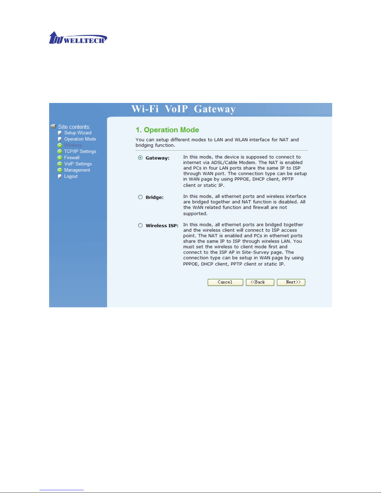
Operation Mode:
You can setup different modes to LAN and WLAN interface for NAT and bridging function.
WG3511N provide all 3 primary modes and 4 extended modes. Here you can find 3 primary modes,
including: 1) Gateway mode, 2) Bridge mode, 3) Wireless ISP. Another 4 extended modes are
changes from these 3 mainly modes and plus some application, including: 1) Client mode, 2) WDS
Repeater Mode, 3) Universal Repeater mode, 4) WISP + Universal Repeater mode.
¾ Gateway: In this mode, the device is supposed to connect to internet via ADSL/Cable Modem.
The NAT is enabled and PCs in four LAN ports share the same IP to ISP through WAN port.
The connection type can be setup in WAN page by using PPPOE, DHCP client or static IP.
¾ Bridge: In this mode, all Ethernet ports and wireless interface are bridged together and NAT
function is disabled. All the WAN related function and firewall are not supported
¾ Wireless ISP: In this mode, all Ethernet ports are bridged together and the wireless client will
Page 17
WellGate 3511N Technical Manual EN-V100
Copyright © 2007 Welltech Computer Co., Ltd. All right reserved.
17
connect to ISP access point. The NAT is enabled and PCs in Ethernet ports share the same
IP to ISP through wireless LAN. You must set the wireless to client mode first and connect to
the ISP AP in Site-Survey page. The connection type can be setup in WAN page by using
PPPOE, DHCP client or static IP.
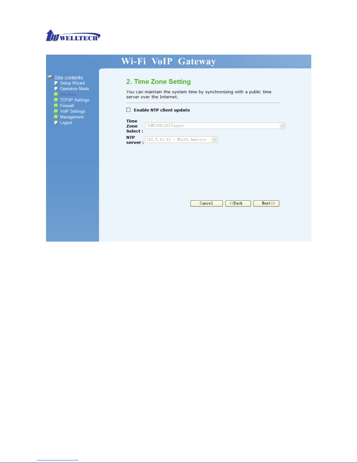
Time Zone Setting
You can maintain the system time by synchronizing with a public time server over the Internet.
¾ Enable NTP client update: User can update time of WG3511N from NTP server if this function
is enabled.
¾ Time Zone Select: Select the time zone according to location.
¾
NTP server: User may select one NTP server for WG3511N to update current time.
Page 18
WellGate 3511N Technical Manual EN-V100
Copyright © 2007 Welltech Computer Co., Ltd. All right reserved.
18
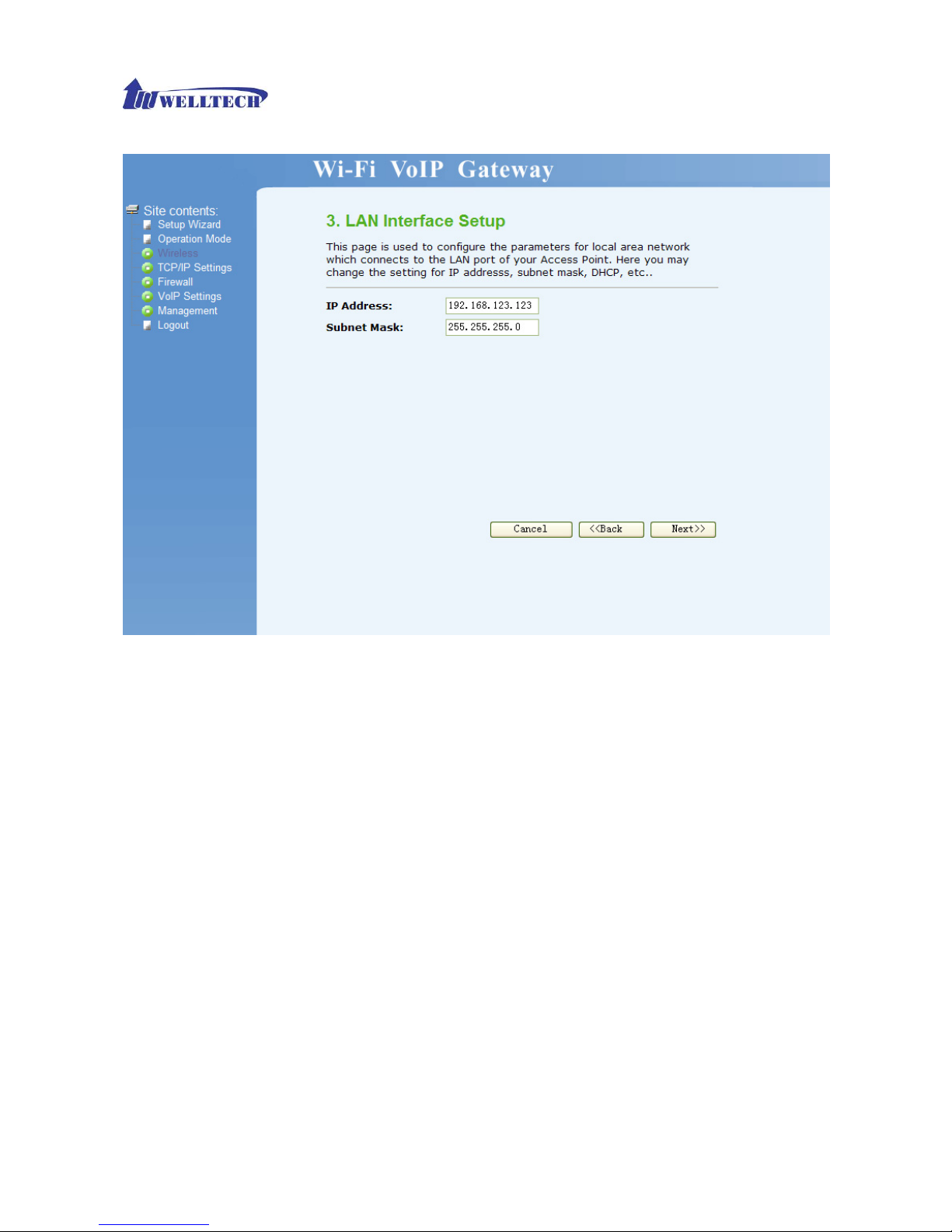
LAN Interface Setup
This page is used to configure the parameters for local area network which connects to the LAN
port of your Access Point. Here you may change the setting for IP address, subnet mask, DHCP,
etc…
¾ IP Address: Set IP address of LAN interface.
¾ Subnet Mask: Set subnet mask of LAN interface.
Page 19
WellGate 3511N Technical Manual EN-V100
Copyright © 2007 Welltech Computer Co., Ltd. All right reserved.
19
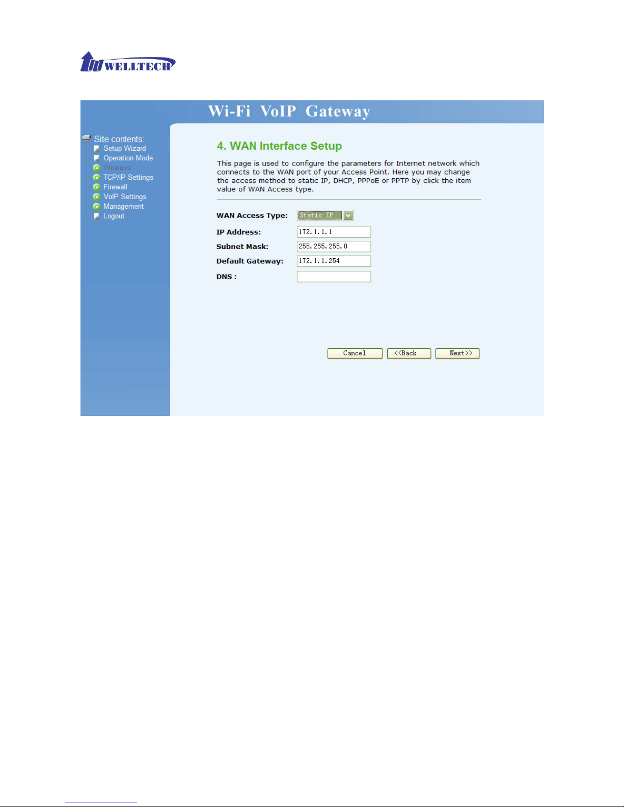
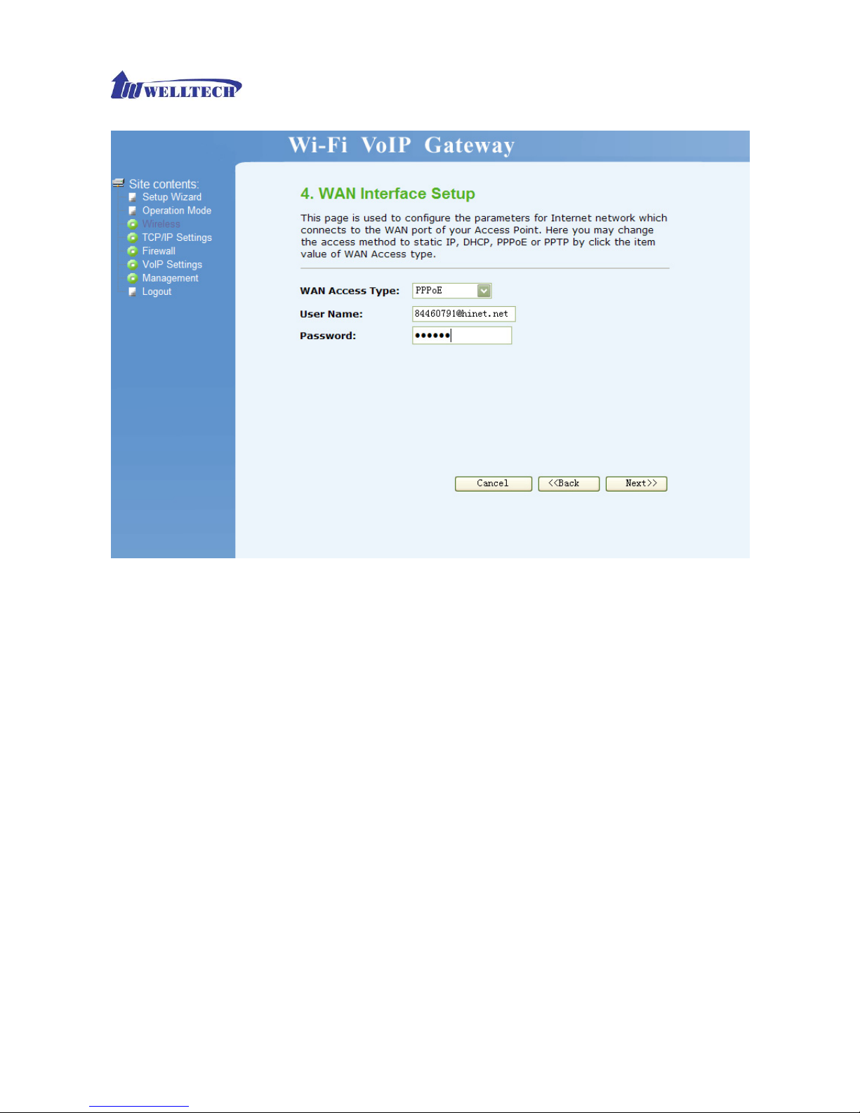
WAN Interface Setup
This page is used to configure the parameters for Internet network which connects to the WAN port
of your Access Point. Here you may change the access method to static IP, DHCP, PPPoE or PPTP
by click the item value of WAN Access type.
¾ Static IP: Set WAN interface as Static IP mode.
1) IP Address: set IP address of WAN interface.
2) Subnet Mask: set subnet mask of WAN interface.
3) Default Gateway: set default gateway of WAN interface.
4) DNS: set Domain Name Server for WAN interface.
Page 20
WellGate 3511N Technical Manual EN-V100
Copyright © 2007 Welltech Computer Co., Ltd. All right reserved.
20
¾ DHCP Client: Set WAN interface as DHCP mode.
Page 21

WellGate 3511N Technical Manual EN-V100
Copyright © 2007 Welltech Computer Co., Ltd. All right reserved.
21
¾ PPPoE: Set WAN interface as PPPoE mode.
1) User Name: Set user name of PPPoE connection.
2) Password: Set password of PPPoE connection.
Page 22
WellGate 3511N Technical Manual EN-V100
Copyright © 2007 Welltech Computer Co., Ltd. All right reserved.
22
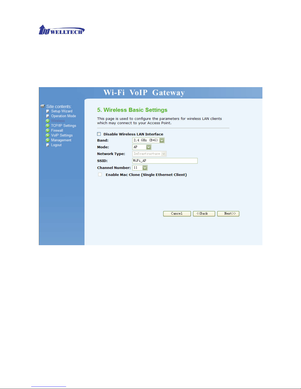
Wireless Basic Settings
This page is used to configure the parameters for wireless LAN clients, which may connect to your
Access Point.
¾ Band: Select wireless band as 802.11b, 802.11g, or 802.11b+g.
¾ Mode: Select wireless mode. User could find 4 different modes here, including AP, Client,
WDS, AP+WDS. AP mode enables WG3511N as wireless access point and allows other
devices to connect wirelessly to a wired Ethernet network. Client mode enables WG3511N to
perform as a wireless client card and other devices can connect with Ethernet cable to
WG3511N. WDS mode is to extend the wireless coverage of another wireless AP. AP+WDS
enables WG3511N to perform as an AP and a WDS repeater. Here we will guide you how to
setup it with AP mode.
¾ Network Type: Only when wireless mode set as client, user can select network type as
infrastructure or Ad hoc. Infrastructure represents a wireless network centered about an
access point. Ad hoc represents a wireless network composed only of stations within mutual
communication range of each other.
¾ SSID: specify to the WG3511N an SSID (Service Set Identifier), which is a unique identifier
attached to packets over WLAN. The SSID is up to 32 ASCII characters that differentiate the
WG3511N from other WiFi AP, and it is also referred to as the ESSID (Extended Service Set
Identifier). You may use the default SSID unless there more than one WG3511N in the same
Page 23
WellGate 3511N Technical Manual EN-V100
Copyright © 2007 Welltech Computer Co., Ltd. All right reserved.
23
area. In this case, you should specify different SSID for each WG3511N.
¾ Channel Number: Set channel for wireless connection. You can set channel for radio
communication manually. If you set it as Auto, the WG3511N will select a clear channel during
boot up.
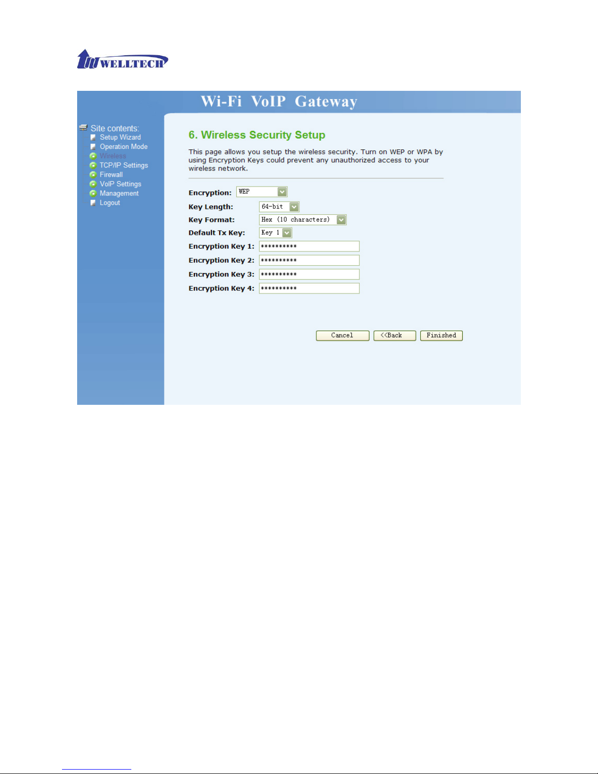
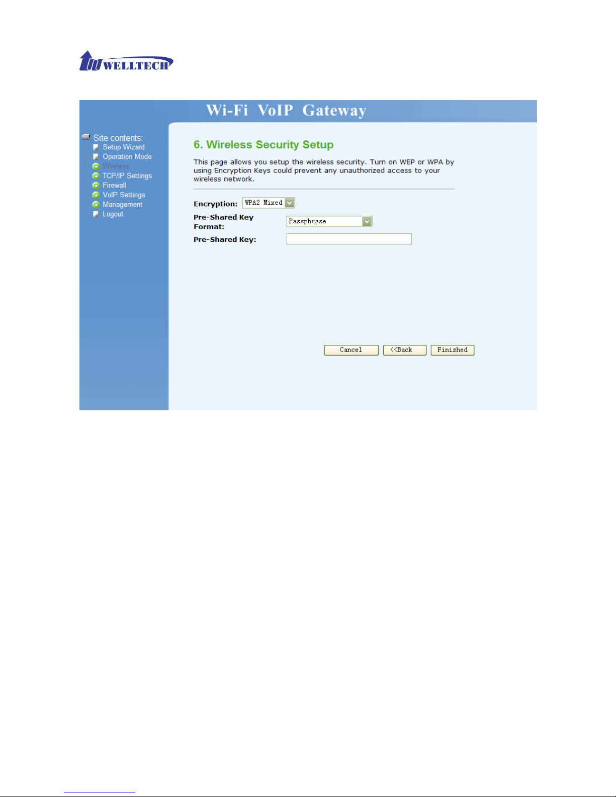
Wireless Security Setup
This page allows you setup the wireless security. Turn on WEP or WPA by using Encryption Keys
could prevent any unauthorized access to your wireless network.
¾ Encryption: Set encryption as none, WEP, WPA, WPA2 or WPA2 Mixed.
Page 24

WellGate 3511N Technical Manual EN-V100
Copyright © 2007 Welltech Computer Co., Ltd. All right reserved.
24
1) WEP: When encryption WEP is selected, you must set WEP key value. Only user with the
same WEP key can connect to the WG3511N.
• Key Length: set WEP key length as 64 or 128 bits and select user to transmit data
using 64 or 128 bits WEP key encryption. 64 bits represents a lower level encryption
for security, and uses ASCII (5 characters) or Hex (10 characters) encryption
scheme as a secret key. 128 bits represents a higher level encryption for security,
and uses ASCII (13 characters) or Hex (26 characters) encryption scheme as a
secret key.
• Key Format: set key format as ASCII (5 characters) or Hex (10 characters) for 64
bits encryption; ASCII (13 characters) or Hex (26 characters) for 128 bits encryption.
• Default Tx Key: set default key as key 1, 2, 3, or 4. User can specify which of the
four keys to use for transmitting data over WLAN.
• Encryption Key 1/2/3/4: user can set 4 sets of encryption keys. Keys 1-4 allow you to
easily change wireless encryption settings to maintain a secure network. WEP key is
either 5/10 or 13/26 ASCII/hexadecimal characters based on user select 64 or 128
bits key length.
Page 25
WellGate 3511N Technical Manual EN-V100
Copyright © 2007 Welltech Computer Co., Ltd. All right reserved.
25
2) WPA(TKIP): only user with the same WPA pre-shared key can connect to WG3511N and
transmit data using TKIP encryption.
• Pre-Shared Key Format: Select Pre-Shared Key Format as Passphrase or Hex (64
characters).
• Pre-Shared Key: set pre-shared key manually.
Page 26

WellGate 3511N Technical Manual EN-V100
Copyright © 2007 Welltech Computer Co., Ltd. All right reserved.
26
3) WPA2(AES): AES ( Advance Encryption Standard) is the U.S. government’s next
generation cryptography algorithm.
• Pre-Shared Key Format: Select Pre-Shared Key Format as Passphrase or Hex (64
characters).
• Pre-Shared Key: set pre-shared key manually.
Page 27

WellGate 3511N Technical Manual EN-V100
Copyright © 2007 Welltech Computer Co., Ltd. All right reserved.
27
4) WPA2 Mixed
• Pre-Shared Key Format: Select Pre-Shared Key Format as Passphrase or Hex (64
characters).
• Pre-Shared Key: set pre-shared key manually.
Page 28
WellGate 3511N Technical Manual EN-V100
Copyright © 2007 Welltech Computer Co., Ltd. All right reserved.
28
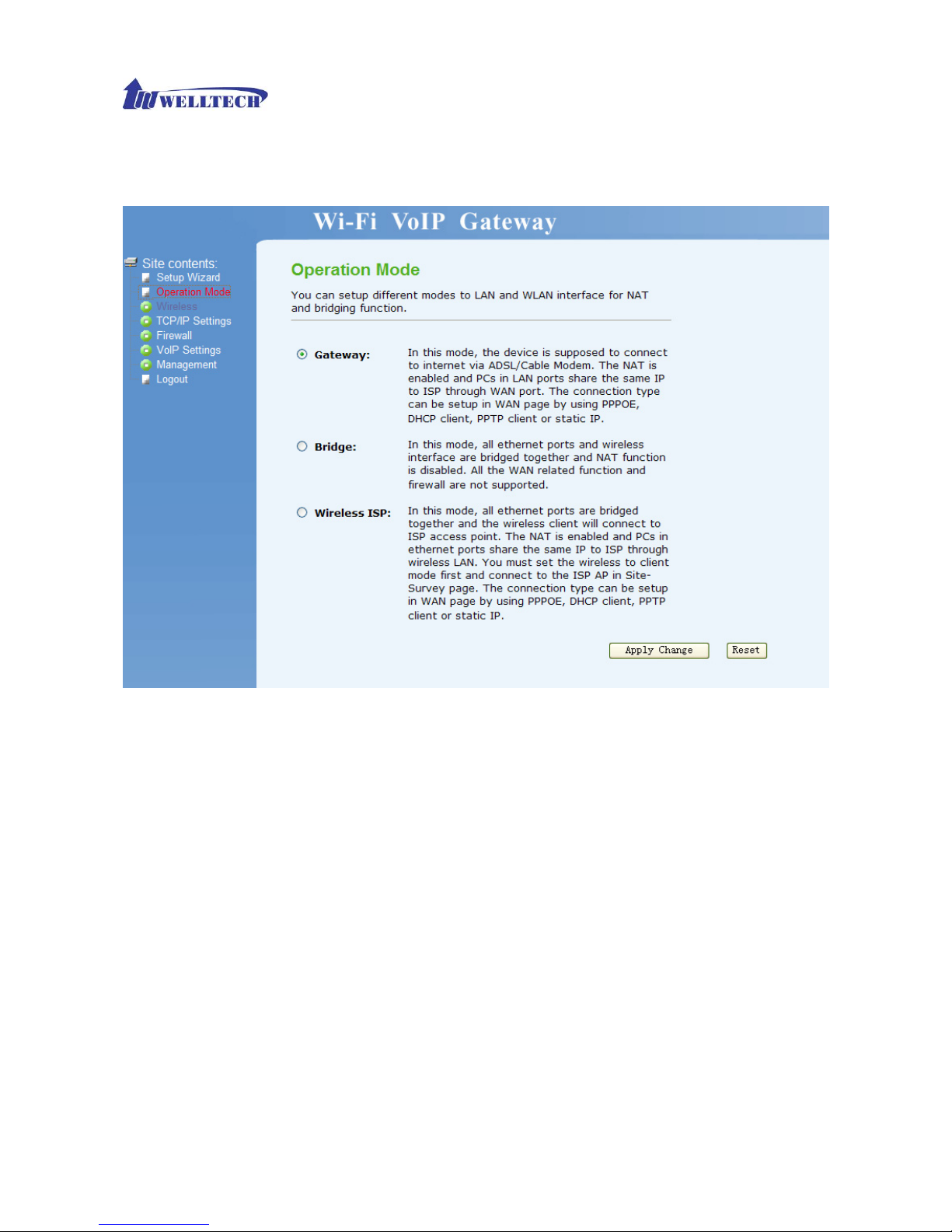
Operation Mode
You can setup different modes to LAN and WLAN interface for NAT and bridging function. WG3511N provide
all 3 primary modes and 4 extended modes. Here you can find 3 primary modes, including: 1) Gateway mode,
2) Bridge mode, 3) Wireless ISP. Another 4 extended modes are changes from these 3 mainly modes and plus
some application, including: 1) Client mode, 2) WDS Repeater Mode, 3) Universal Repeater mode, 4) WISP +
Universal Repeater mode.
Gateway: In this mode, the device is supposed to connect to internet via ADSL/Cable Modem. The
NAT is enabled and PCs in four LAN ports share the same IP to ISP through WAN port. The
connection type can be setup in WAN page by using PPPOE, DHCP client or static IP.
Bridge: In this mode, all Ethernet ports and wireless interface are bridged together and NAT
function is disabled. All the WAN related function and firewall are not supported
Wireless ISP: In this mode, all Ethernet ports are bridged together and the wireless client will
connect to ISP access point. The NAT is enabled and PCs in Ethernet ports share the same IP to
ISP through wireless LAN. You must set the wireless to client mode first and connect to the ISP AP
in Site-Survey page. The connection type can be setup in WAN page by using PPPOE, DHCP
client, PPTP Client or static IP.
For more information regarding Operation Modes, please refer to Chapter 4 Wireless
Page 29
WellGate 3511N Technical Manual EN-V100
Copyright © 2007 Welltech Computer Co., Ltd. All right reserved.
29
Operation Modes.
Wireless
Basic Settings
This page is used to configure the parameters for wireless LAN clients which may connect to your
Access Point.
¾ Disable Wireless LAN Interface: If user checks his function, wireless LAN will be disabled. In
other words, this device will not be visible by any wireless station.
¾ Band: Select wireless band as 802.11b, 802.11g, or 802.11b+g.
¾ Mode: Select wireless mode as AP, Client, WDS and AP+WDS. AP mode enables WG3511N
to work as wireless an access point and allow other devices to connect wirelessly to a wired
Ethernet network. Client mode enables WG3511N to perform as a wireless client card and
other devices can connect with Ethernet cable to WG3511N. WDS and AP+WDS are used for
Repeater. If AP+WDS is enabled, WG3511N could be working as AP and WDS Repeater
together.
¾ Network Type: Only when wireless mode set as client, user can select network type as
infrastructure or Ad hoc. Infrastructure represents a wireless network centered about an
access point. Ad hoc represents a wireless network composed only of stations within mutual
communication range of each other. (No Access Point).
Page 30

WellGate 3511N Technical Manual EN-V100
Copyright © 2007 Welltech Computer Co., Ltd. All right reserved.
30
¾ SSID: specify to the WG3511N an SSID (Service Set Identifier), which is a unique identifier
attached to packets over WLAN. The SSID is up to 32 ASCII characters that differentiate the
WG3511N from other WiFi AP, and it is also referred to as the ESSID (Extended Service Set
Identifier). You may use the default SSID unless there more than one WG3511N in the same
area. In this case, you should specify different SSID for each WG3511N.
¾ Channel Number: Set channel for wireless connection. You can set channel for radio
communication manually. If you set it as Auto, the WG3511N will select a clear channel during
boot up.
¾ Associated Clients: Press Show Active Clients to see which client registers on this WG3511N.
¾ Enable Universal Repeater Mode (Acting as AP and client simultaneously): Enable this
feature will perform WG3511N to work as Universal Repeater.
¾ SSID of Extended Interface: User could input SSID of Extended Interface here if Universal
Repeater is enabled.
¾ Disable WiFi Activation Schedule: Wifi Activation schedule is used for energy saving (green
feature) which allows to turn off the wifi RF and feature based on the preset week daytime.
When hardware Wifi switch is switch off, the Wifi Activation Schedule will be ignore. It only
works when Wifi switch is turned ON.
- Active time: The time to turn on the Wifi RF and feature (24 hours format)
- End time: The time to turn off the Wifi RF and feature (24 hours format)
For more information regarding WDS, AP+WDS and Universal Repeater mode, please refer
to Chapter 4 Wireless Operation Modes.
Page 31

WellGate 3511N Technical Manual EN-V100
Copyright © 2007 Welltech Computer Co., Ltd. All right reserved.
31
Advanced Setting
These settings are only for more technically advanced users who have a sufficient knowledge
about wireless LAN. These settings should not be changed unless you know what effect the
changes will have on your Access Point.
¾ Authentication Type: Select authentication type as Open System, Shared Key, or Auto. With
Open System authentication, a wireless PC can join any network and receive any messages
that are not encrypted. With Shared Key authentication, only those PCs that possess the
Page 32

WellGate 3511N Technical Manual EN-V100
Copyright © 2007 Welltech Computer Co., Ltd. All right reserved.
32
correct authentication key can join the network.
¾ Fragment Threshold (256-2346): set fragment threshold size. Fragments are small pieces
divided from 802.11 frames. If there are excessive collisions over WLAN, user can try different
fragment size to increase reliability.
¾ RTS Threshold (0-2347): RTS Threshold is a mechanism implemented to prevent the
problem of “Hidden Node”. “Hidden Node” is a situation in which two stations are within range
of the same Access Point, but are not within range of each other. Therefore, they are hidden
nodes for each other. When station starts data transmission with the Access Point, it might not
notice that the other station is already using the wireless medium. When these two stations
send data at the same time, they might collide when arriving simultaneously at the Access
Point. The collision will most certainly result in a loss of messages for both stations. Thus, the
RTS Threshold mechanism provides a solution to prevent data collisions. If the “Hidden
Node” problem is an issue, please specify the packet size. The RTS mechanism will be
activated if the data size exceeds the value you set. Default value is 2347.
¾ Beacon Interval: set beacon interval time in milliseconds. System broadcast packet or a
beacon to synchronize the wireless network.
¾ Data Rate: specify the transmission rate. Leave on “Auto” to maximize performance versus
distance.
¾ Preamble Type: A preamble is a signal used in wireless environment to synchronize the
transmitting timing including Synchronization and Start frame delimiter. In a “noisy” network
environment, the Preamble Type should be set to Long Preamble. The Short Preamble is
intended for applications where minimum overhead and maximum performance is desired.
¾ Broadcast SSID: enable or disable SSID broadcast function. If user enables this function,
other wireless clients can broadcast and find this wireless AP to connect.
¾ IAPP: IAPP is a portable implementation of the 802.11F specification for Inter Access Point
Protocol (IAPP) to enable end-station mobility across Access Points.
¾ RF Output Power: set radio output power level as 100%, 50%, 25%, 10% or 5%.
¾ 802.11g Protection: Enable or disable 802.11g protection mode.
¾ WMM: Enable WiFi Multimedia support which
maintains the priority of audio, video and
voice applications in a Wi-Fi network so that other applications and traffic are less
likely to slow them.
¾ Turbo Mode: Enable 802.11 turbo mode or not. Please note it will have compatible issue
when using auto or always mode.
Page 33

WellGate 3511N Technical Manual EN-V100
Copyright © 2007 Welltech Computer Co., Ltd. All right reserved.
33
Security
This page allows you setup the wireless security. Turn on WEP or WPA by using Encryption Keys
could prevent any unauthorized access to your wireless network.
¾ Encryption: Set encryption as none, WEP, WPA, WPA2 or WPA2 Mixed.
¾ Set WEP Key: When encryption WEP is selected, you must set WEP key value.
1) Key Length: Set WEP key length as 64 or 128 bits.
2) Key Format: Set key format as ASCII (5 characters) if you are using ASCII characters.
Select HEX if you are using hexadecimal numbers.
3) Default Tx Key: Set default transmit key as key 1, 2, 3, or 4.
4) Encryption Key 1/2/3/4: user can set 4 sets of encryption keys. Keys 1-4 allow you to
easily change wireless encryption settings to maintain a secure network. WEP key is
either 5/10 or 13/26 ASCII/hexadecimal characters based on user select 64 or 128 bits
key length.
10 hexadecimal digits or 5 ASCII characters are needed if 64 bit WEP is used; 26
hexadecimal digits or 13 ASCII characters are needed if 64 bit WEP is used
¾ Use 802.1x Authentication: Check to use Radius 802.1x authentication and select
authentication level as WEP 64 bits or 128bits. In this case, please set Authentication
Page 34

WellGate 3511N Technical Manual EN-V100
Copyright © 2007 Welltech Computer Co., Ltd. All right reserved.
34
RADIUS Server information.
¾ WPA Authentication Mode: Select WPA authentication mode as Enterprise (RADIUS) or
Personal (Pre-Shared Key). If user select Enterprise mode, please fill in Authentication
RADIUS Server information. If user select Personal mode, please select Pre-Shared key
format and fill in Pre-Shared Key.
¾ WPA Cipher Suite: Select WPA Cipher Suite to be TKIP or AES, this field is used as a
password to begin the encryption process.
¾ WPA2 Cipher Suite: Select WPA Cipher Suite to be TKIP or AES.
WPA is an encryption standard proposed by WiFi for advance protection. It is more secure
than WEP encryption.
¾ Pre-Shared Key Format: There are two formats for choice to set the Pre-Shared key, i.e.
Passphrase and Hex. Select Pre-Shared Key Format as Passphrase (at least 8 characters)
or Hex (64 characters). For easier configuration, The Passphrase is recommended.
¾ Pre-Shared Key: Set pre-shared key manually.
When WPA is enabled and the WPA Authentication Mode is set to Personal. You should also
input Pre-shared Key for encryption.
¾ Enable Pre-Authentication: Pre-Authentication, which enables secure fast roaming without
noticeable signal latency, provides a way to establish a PMK security association before a
client associates. The advantage is that the client reduces the time that it’s disconnected to
the network.
¾ Authentication RADIUS Server: set port, IP address, and password of Radius Server for
WG3511 to initial a Radius connection and get dynamic WEP key.
Page 35

WellGate 3511N Technical Manual EN-V100
Copyright © 2007 Welltech Computer Co., Ltd. All right reserved.
35
Page 36

WellGate 3511N Technical Manual EN-V100
Copyright © 2007 Welltech Computer Co., Ltd. All right reserved.
36
Access Control
If you choose Allowed Listed, only those clients whose wireless MAC addresses are in the access
control list will be able to connect to your Access Point. When Deny Listed is selected, these
wireless clients on the list will not be able to connect the Access Point.
¾ Wireless Access Control Mode: Set disable control, allow list or deny list.
If user set control mode as Allow Listed, please add MAC address below to increase Allow
List. If user set control mode as Deny Listed, please add MAC address below to increase
Deny List.
¾ MAC Address: Input MAC address for allow or deny list.
¾ Comment: Give description for each data.
¾ Current Access Control List: Show current control list.
¾ User can press Delete Selected to delete specified data or press Delete All to delete all lists.
WDS Settings
Wireless Distribution System uses wireless media to communicate with other APs, like the Ethernet
does. To do this, you must set these APs in the same channel and set MAC address of other APs
which you want to communicate with in the table and then enable the WDS.
¾ Enable WDS: Enable WDS to start transmitting and receiving WDS packets. You can only use
this feature when wireless mode set to WDS or AP+WDS.
¾ MAC address: Enter 12 digits in hex numbers in this field and press Apply Changes to
associate with other’s Wireless access point. Before you want to use WDS Repeater mode,
you have to enter the other’s AP/Router MAC address that the device want to connect.
Page 37

WellGate 3511N Technical Manual EN-V100
Copyright © 2007 Welltech Computer Co., Ltd. All right reserved.
37
¾ Reset: Reset the settings of WDS.
¾ Set Security: This setting is use between both wireless AP/ Router device.
¾ Show Statistics: Show the current statistics of WDS.
¾ Current WDS AP List: Show the current WDS AP list.
Site Survey
This page provides tool to scan the wireless network. If any Access Point or IBSS is found, you
could choose to connect it manually when client mode is enabled.
Page 38

WellGate 3511N Technical Manual EN-V100
Copyright © 2007 Welltech Computer Co., Ltd. All right reserved.
38
WPS
This page allows you to change the setting for WPS(Wi-Fi Protected Setup). Using this feature
could let your wireless client automatically synchronize its setting and connect to the Access Point
in a minute without any hassle.
¾ Disable WPS : Disable Wi-Fi Protected Setup. WPS is turned on by default
¾ WPS Status: The WPS current status
¾ Self-PIN Number: “Self-PIN Number” is AP’s PIN. Whenever users want to change AP’s PIN,
they could click “Regenerate PIN” and then click “ Apply Changes”. Moreover, if users want to
make their own PIN, they could enter four digit PIN without checksum and then click “ Apply
Changes”. However, this would not be recommended since the registrar side needs to be
supported with four digit PIN.
¾ Start PBC : Clicking this button will invoke the PBC method of WPS. It is only used when AP
acts as a registrar.
Page 39

WellGate 3511N Technical Manual EN-V100
Copyright © 2007 Welltech Computer Co., Ltd. All right reserved.
39
TCP/IP Settings
LAN Interface
¾ IP Address: Set IP address of LAN interface.
¾ Subnet Mask: Set subnet mask of LAN interface.
¾ Default Gateway: Set default gateway of LAN interface. It is normally used when Bridge mode
is enabled.
¾ DHCP: Set DHCP mode to be disabled, Client, or Server. When user set DHCP mode as
server mode, please set DHCP Client Range for LAN interface to assign DHCP IP.
¾ Show Client: Press this key can check current DHCP clients that captured IP from WG3511N.
Press Refresh can renew screen display, and press Close can close window.
¾ DHCP Client Range: Set DHCP IP range for WG3511N to assign IP address for other device
in LAN.
¾ 802.1d Spanning: Enable or disable 802.1d Spanning Tree function.
¾ Clone mac address: Whether clone the specified mac address when send out the traffic or not
¾ Domain name: Specified the domain used
Page 40

WellGate 3511N Technical Manual EN-V100
Copyright © 2007 Welltech Computer Co., Ltd. All right reserved.
40
WAN Interface
This page is used to configure the parameters for Internet network which connects to the WAN port
of your Access Point. Here you may change the access method to static IP, DHCP or PPPoE by
click the item value of WAN Access type.
¾ WAN Access Type: Select WAN mode as Static IP/ DHCP Client/ PPPoE.
1) Static IP: Set WAN interface as Static IP mode.
2) IP Address: Set IP address of WAN interface.
3) Subnet Mask: Set subnet mask of WAN interface.
4) Default Gateway: Set default gateway of WAN interface.
5) MTU Size: Set MTU (maximum transmission unit) size.
6) DNS 1/DNS 2/ DNS 3: Set three alternative Domain Name Server for WAN interface.
7) Enable UPnP: check to enable UPnP function.
8) Enable Ping Access on WAN: If this function is checked to enable, user can reach
WG3511N via Ping WAN IP address.
9) Enable Web Server Access on WAN: If this function is checked to enable, user can enter
Web Server management of WG3511N through WAN IP address.
10) Enable IPsec pass through on VPN connection: check to enable IPsec function.
11) Enable PPTP pass through on VPN connection: check to enable PPTP pass through
function.
12) Enable L2TP pass through on VPN connection: check to enable L2TP pass through
Page 41

WellGate 3511N Technical Manual EN-V100
Copyright © 2007 Welltech Computer Co., Ltd. All right reserved.
41
function.
13) Clone Mac Address: Whether clone the specified mac address when send out the traffic
or not.
¾
DHCP Client: Set WAN interface as DHCP mode.
1) MTU Size: Set MTU (maximum transmission unit) size.
2) Attain DNS Automatically/Set DNS Manually: select to attain DNS automatically from
server or user wants to set DNS manually.
After setting to DHCP, the IP information will be displayed in the page of ManagementÆ
Status.
3) DNS 1/DNS 2/ DNS 3: Set three alternative Domain Name Server manually for WAN
interface.
4) Enable UPnP: check to enable UPnP function.
5) Enable Ping Access on WAN: If this function is checked to enable, user can reach
WG3511N via Ping WAN IP address.
Page 42

WellGate 3511N Technical Manual EN-V100
Copyright © 2007 Welltech Computer Co., Ltd. All right reserved.
42
6) Enable Web Server Access on WAN: If this function is checked to enable, user can enter
Web Server management of WG3511N through WAN IP address.
7) Enable IPsec pass through on VPN connection: check to enable IPsec function.
8) Enable PPTP pass through on VPN connection: check to enable PPTP pass through
function.
9) Enable L2TP pass through on VPN connection: check to enable L2TP pass through
function.
10) Clone MAC Address: Whether clone the specified mac address when send out the traffic or not
¾ PPPoE: Set WAN interface as PPPoE mode.
1) User Name: Set user name of PPPoE connection.
2) Password: Set password of PPPoE connection.
3) Service Name: Set Service Name of PPPoE for description.
4) Connection Type: Set PPPoE connection type to be Continuous/ Connect on Demand/
Manual. If user set type as Continuous, WG3511N will keep trying to connect to server
Page 43

WellGate 3511N Technical Manual EN-V100
Copyright © 2007 Welltech Computer Co., Ltd. All right reserved.
43
when PPPoE disconnect. If user set type as Connect on Demand, please set following
idle time, WG3511N will check connection after this time. If user set type as Manual,
WG3511N will only connect or disconnect by press Connect or Disconnect manually.
5) Idle Time: Set PPPoE connection idle time for Connect on Demand.
6) MTU Size: Set MTU (maximum transmission unit) size.
7) Attain DNS Automatically/Set DNS Manually: Select to attain DNS automatically from
server or user wants to set DNS manually.
8) DNS 1/DNS 2/ DNS 3: Set three alternative Domain Name Server manually for WAN
interface.
9) Enable UPnP: Check to enable UPnP function.
10) Enable Ping Access on WAN: If this function is checked to enable, user can reach
WG3511N via Ping WAN IP address.
11) Enable Web Server Access on WAN: If this function is checked to enable, user can enter
Web Server management of WG3511N through WAN IP address.
12) Enable IPsec pass through on VPN connection: check to enable IPsec function.
13) Enable PPTP pass through on VPN connection: check to enable PPTP pass through
function.
14) Enable L2TP pass through on VPN connection: check to enable L2TP pass through
function.
Page 44

WellGate 3511N Technical Manual EN-V100
Copyright © 2007 Welltech Computer Co., Ltd. All right reserved.
44
Firewall
Port Filtering
Entries in this table are used to restrict certain types of data packets from your local network to
Internet through the Gateway. Use of such filters can be helpful in securing or restricting your local
network.
Page 45

WellGate 3511N Technical Manual EN-V100
Copyright © 2007 Welltech Computer Co., Ltd. All right reserved.
45
¾ Enable Port Filtering: check to enable Port Filtering function.
¾ Port Range: set start port and end port for port filtering range.
¾ Protocol: set protocol as TCP or UDP or both protocol.
¾ Comment: Make description for this port filtering rule.
IP Filtering
Entries in this table are used to restrict certain types of data packets from your local network to
Internet through the Gateway. Use of such filters can be helpful in securing or restricting your local
network.
¾ Enable IP Filtering: check to enable IP Filtering function.
¾ Local IP Address: set IP Address for IP filtering.
¾ Protocol: set protocol as TCP or UDP or both protocol.
¾ Comment: Make description for this IP filtering rule.
Page 46

WellGate 3511N Technical Manual EN-V100
Copyright © 2007 Welltech Computer Co., Ltd. All right reserved.
46
MAC Filtering
Entries in this table are used to restrict certain types of data packets from your local network to
Internet through the Gateway. Use of such filters can be helpful in securing or restricting your local
network.
¾ Enable MAC Filtering: check to enable MAC Filtering function.
¾ MAC Address: set MAC Address for MAC filtering.
¾ Comment: Make description for this MAC filtering rule.
Page 47

WellGate 3511N Technical Manual EN-V100
Copyright © 2007 Welltech Computer Co., Ltd. All right reserved.
47
URL Filtering
URL filter is used to deny LAN users from accessing the internet. Block those URLs which contain
keywords listed below.
¾ Enable URL Filtering: check to enable URL Filtering function.
¾ URL Address: set URL address for URL filtering function.
Page 48

WellGate 3511N Technical Manual EN-V100
Copyright © 2007 Welltech Computer Co., Ltd. All right reserved.
48
Port Forwarding
Entries in this table allow you to automatically redirect common network services to a specific
machine behind the NAT firewall. These settings are only necessary if you wish to host some sort
of server like a web server or mail server on the private local network behind your Gateway's NAT
firewall.
¾ Enable Port Forwarding: check to enable Port Forwarding function.
¾ IP Address: set IP address for port forwarding.
¾ Protocol: Set Protocol type for port forwarding.
¾ Port Range: set start port and end port for port forwarding range.
¾ Comment: Make description for this port forwarding rule.
Page 49

WellGate 3511N Technical Manual EN-V100
Copyright © 2007 Welltech Computer Co., Ltd. All right reserved.
49
DMZ
A Demilitarized Zone is used to provide Internet services without sacrificing unauthorized access to
its local private network. Typically, the DMZ host contains devices accessible to Internet traffic,
such as Web (HTTP ) servers, FTP servers, SMTP (e-mail) servers and DNS servers.
¾ Enable DMZ: check to enable DMZ function.
¾ DMZ Host Address: set IP address for DMZ function.
Page 50

WellGate 3511N Technical Manual EN-V100
Copyright © 2007 Welltech Computer Co., Ltd. All right reserved.
50
VoIP Settings
Home User Wizard
The setup Home User wizard will guide you to configure VoIP setting for regular user setting. Please follow
the setup Home User wizard step by step for your VOIP settings.
Page 51

WellGate 3511N Technical Manual EN-V100
Copyright © 2007 Welltech Computer Co., Ltd. All right reserved.
51
¾ VoIP Provider Setup
This page is used to configure the parameters for VoIP provider. Here you may enable proxy by click the
item then you register to the SIP Proxy Server.
1. Display Name: Set Phone (FXS) SIP display name for caller ID information
2. Number: Set SIP registering Phone number.
3. Login ID: If Proxy server needs registration authentication please input Login ID here.
4. Password: If Proxy server needs registration authentication please input password here SIP Proxy
5. Proxy Addr: If user enable Proxy mode, please input Proxy address.
6. Proxy Port: If user enable Proxy mode, please input Proxy port.
7. SIP Domain: Set SIP domain name for SIP signaling.
8. Reg Expire(sec): Set expire time of registration. WG3511N will keep re-registering to proxy server
before expire timed out
9. Outbound Proxy: Check to enable Outbound Proxy mode.
10. Outbound Proxy Addr: If user enables Outbound Proxy, please input Outbound Proxy address.
11. Outbound Proxy Port: If user enables Outbound Proxy, please input Outbound Proxy port.
Page 52

WellGate 3511N Technical Manual EN-V100
Copyright © 2007 Welltech Computer Co., Ltd. All right reserved.
52
¾ Caller ID for Phone Setting
This page is used to configure the parameters for DSP Caller ID. Here you can set the Caller ID Mode
to show Caller ID in your PSTN Phone or IP Phone.
9 DTMF : Set Call ID as DTMF mode.
Reverse Polarity before Caller ID: Check to send reverse polarity before caller ID.
Short Ring before Caller ID: Check to send short ring before caller ID.
Caller ID Prior First Ring: Check to send caller ID before first ring.
Caller ID DTMF Start Digit: Set caller ID DTMF start digit.
Caller ID DTMF End Digit: Set caller ID DTMF end digit.
9 FSK_BELLCORE: Set Call ID as FSK_BELLCORE mode
FSK Date & Time Sync: Check to send FSK Date and Time to caller ID display device.
Reverse Polarity before Caller ID: Check to send reverse polarity before caller ID.
Short Ring before Caller ID: Check to send short ring before caller ID.
Dual Tone before Caller ID: Check to send dual tone before caller ID.
Caller ID Prior First Ring: Check to send caller ID before first ring.
Page 53

WellGate 3511N Technical Manual EN-V100
Copyright © 2007 Welltech Computer Co., Ltd. All right reserved.
53
9 FSK_ETSI: Set Call ID as FSK_ETSI mode
FSK Date & Time Sync: Check to send FSK Date and Time to caller ID display device.
Reverse Polarity before Caller ID: Check to send reverse polarity before caller ID.
Short Ring before Caller ID: Check to send short ring before caller ID.
Dual Tone before Caller ID: Check to send dual tone before caller ID.
Caller ID Prior First Ring: Check to send caller ID before first ring.
Page 54

WellGate 3511N Technical Manual EN-V100
Copyright © 2007 Welltech Computer Co., Ltd. All right reserved.
54
9 FSK_BT: Set Call ID as FSK_BT mode
FSK Date & Time Sync: Check to send FSK Date and Time to caller ID display device.
Reverse Polarity before Caller ID: Check to send reverse polarity before caller ID.
Short Ring before Caller ID: Check to send short ring before caller ID.
Dual Tone before Caller ID: Check to send dual tone before caller ID.
Caller ID Prior First Ring: Check to send caller ID before first ring.
Page 55

WellGate 3511N Technical Manual EN-V100
Copyright © 2007 Welltech Computer Co., Ltd. All right reserved.
55
9 FSK_NTT: Set Call ID as FSK_NTT mode
FSK Date & Time Syn: Check to send FSK Date and Time to caller ID display device.
Reverse Polarity before Caller ID: Check to send reverse polarity before caller ID.
Short Ring before Caller ID: Check to send short ring before caller ID.
Dual Tone before Caller ID: Check to send dual tone before caller ID.
Caller ID Prior First Ring: Check to send caller ID before first ring.
Page 56

WellGate 3511N Technical Manual EN-V100
Copyright © 2007 Welltech Computer Co., Ltd. All right reserved.
56
¾ PSTN Routing Prefix Setup
This page is used to configure the parameter for PSTN prefix. Here you can set the prefix list to dial out from PSTN, it
doesn't need to dial *0 to switch to PSTN.
Page 57

WellGate 3511N Technical Manual EN-V100
Copyright © 2007 Welltech Computer Co., Ltd. All right reserved.
57
¾ PSTN to VoIP Setup
This page is used to configure the parameters for Call Forward. Here you can setup the phone number you want to
forward. There are three type of No Answer Forward for PSTN. You can choose 2 Stage Dialing, Direct Forward, and
turn off Forward by click the item value of No Answer Forward for PSTN.
9 Off: FXO (PSTN) is send directly to FXS without any forward setting. This is the default
behavior.
Page 58

WellGate 3511N Technical Manual EN-V100
Copyright © 2007 Welltech Computer Co., Ltd. All right reserved.
58
9 2 Stage Dialing: The FXO (PSTN) call will be routed to FXS first. If FXS (Phone) doesn’t
answer within the time of “No Answer Time for PSTN”. The FXO will answer the call and
asked for PIN code (if set in FXO -> Authentication Password) or called number. After the
called number was collected, the call will be routed to VOIP for calling out.
No Answer Number for PSTN: It is not used for this case.
No Answer Time for PSTN: If FXS (phone) is not answered within this time, the call will be
forwarded.
Display Name: When enable PSTN to VOIP, it requires additional SIP account for calling out. This is
the call out SIP account’s display name.
Number: PSTN to VOIP calling out SIP register TEL number
Login ID: PSTN to VOIP calling out SIP authentication user ID
Password: PSTN to VOIP calling out SIP authentication user password
Proxy Addr: PSTN to VOIP calling out SIP proxy server address
Proxy Port: PSTN to VOIP calling out SIP proxy server port
SIP Domain: PSTN to VOIP calling out SIP register domain
Reg Expire (sec): Set expire time of registration. WG3511N will keep re-registering to proxy server
before expire timed out
Outbound Proxy: Enable or disable to use outbound proxy server
Outbound Proxy Addr: PSTN to VOIP calling out SIP outbound proxy server
Outbound Proxy Port: PSTN to VOIP calling out SIP outbound proxy server port
Page 59

WellGate 3511N Technical Manual EN-V100
Copyright © 2007 Welltech Computer Co., Ltd. All right reserved.
59
9 Direct Forward: The FXO (PSTN) call will be routed to FXS first. If FXS (Phone) doesn’t
answer within the time of “No Answer Time for PSTN”. The call will be routed to VOIP based
on the “No Answer Number for PSTN”.
No Answer Number for PSTN: The number to be routed through VOIP calling out account.
No Answer Time for PSTN: If FXS (phone) is not answered within this time, the call will be
forwarded.
Display Name: When enable PSTN to VOIP, it requires additional SIP account for calling out. This is
the call out SIP account’s display name.
Number: PSTN to VOIP calling out SIP register TEL number
Login ID: PSTN to VOIP calling out SIP authentication user ID
Password: PSTN to VOIP calling out SIP authentication user password
Proxy Addr: PSTN to VOIP calling out SIP proxy server address
Proxy Port: PSTN to VOIP calling out SIP proxy server port
Page 60

WellGate 3511N Technical Manual EN-V100
Copyright © 2007 Welltech Computer Co., Ltd. All right reserved.
60
SIP Domain: PSTN to VOIP calling out SIP register domain
Reg Expire (sec): Set expire time of registration. WG3511N will keep re-registering to proxy server
before expire timed out
Outbound Proxy Enable: Enable or disable to use outbound proxy server
Outbound Proxy Addr: PSTN to VOIP calling out SIP outbound proxy server
Outbound Proxy Port: PSTN to VOIP calling out SIP outbound proxy server port
Page 61

WellGate 3511N Technical Manual EN-V100
Copyright © 2007 Welltech Computer Co., Ltd. All right reserved.
61
FXS
Here is to set VoIP Phone related configurations.
¾ SIP Account
1) Display Name: Set SIP Phone display name for caller ID information.
2) Number: Set registering Phone number.
3) Login ID: If Proxy server needs registration authentication please input Login ID here.
4) Password: If Proxy server needs registration authentication please input password here.
¾ SIP Proxy
1) Display Name: Set Phone display name for caller ID information
2) Number: Set registering Phone number.
3) Login ID: If Proxy server needs registration authentication please input Login ID here.
4) Password: If Proxy server needs registration authentication please input password here
SIP Proxy
5) Proxy : Check to enable Proxy mode.
6) Proxy Addr: If user enable Proxy mode, please input Proxy address.
7) Proxy Port: If user enable Proxy mode, please input Proxy port.
8) SIP Domain: Set SIP domain name for SIP signaling.
9) Reg Expire(sec): Set expire time of registration. WG3511N will keep re-registering to
proxy server before expire timed out
10) Outbound Proxy : Check to enable Outbound Proxy mode.
11) Outbound Proxy Addr: If user enables Outbound Proxy, please input Outbound Proxy
address.
12) Outbound Proxy Port: If user enables Outbound Proxy, please input Outbound Proxy port.
13) Nortel SoftSwitch: Check to enable Nortel SIP PING function. Please only used it for
Nortel softswitch.
14) Register Status: Here will display SIP account register status.
¾ NAT Traversal
1) Stun : check to enable STUN function.
2) Stun Server Addr: If user enables STUN function, please input STUN Server address.
3) Stun Server Port: If user enables STUN function, please input STUN Server port.
¾ SIP Advanced
1) SIP Port: Set local SIP listening port.
2) Media Port: Set RTP port for sending voice data.
3) DTMF Relay: Select DTMF Relay to be In band, RFC 2833, or SIP INFO.
4) RFC2833 Payload Type: If user select DTMF as RFC 2833 type, here can modify RFC
2833 payload type.
Page 62

WellGate 3511N Technical Manual EN-V100
Copyright © 2007 Welltech Computer Co., Ltd. All right reserved.
62
5) SIP INFO Duration (ms): If user select DTMF as SIP INFO type, here can modify SIP
INFO duration. Gateway will send out DTMF as this duration.
6) Call Waiting Enable: Check to enable Call Waiting function.
7) Call Waiting Caller ID Enable: Check to enable call waiting caller ID function. If this
function is enabled, caller ID will display when having waiting call. Please note that your
phone set should also support such function.
8) Reject Peer to Peer Call : Reject those call not from register SIP proxy server.
¾ Forward Mode
1) Immediate Forward to: This is unconditional forward setting. All incoming call will be
forwarded to specified number. Check to enable immediate forward function.
2) Immediate Forward Number: Enter the assigned number for Immediate forward.
3) Busy Forward to: Check to enable Busy Forward function. When phone is busy, incoming
call will be forwarded to assigned number.
4) Busy Number: Enter the assigned number for busy forward.
5) No Answer Forward to: Check to enable no answer forward function. When phone is not
answered for a period of time, incoming call will be forwarded to assigned number.
6) No Answer Number: Enter assigned number for no answer forward.
7) No Answer Time (sec): Set no answer time. Once phone is not picked up after this time,
incoming call be will forwarded to assigned number.
8) No Answer Forward for PSTN: Enable or disable PSTN incoming call no answer forward
when FXS is not answered.
9) No Answer Number for PSTN: No answer forward number for PSTN incoming call and
used to forward through VOIP calling account.
10) No Answer Time for PSTN: No answer time out for FXO/PSTN incoming call
¾ Speed Dial
1) Position: Speed Dial access code. Press this speed dial number and followed by # can
dial out assigned phone number.
2) Name: Name of this speed dial.
3) Phone Number: Set phone number for Gateway to make speed dial.
4) Select: User can delete selected speed dial data.
¾ Abbreviated Dial
1) Abbreviated Number: The abbreviated number for dialing
2) Phone Number: The phone number to be replaced when abbreviated number is dialed.
¾ Dial Plan
1) Replace prefix code: Select to enable (On) or disable (Off) prefix replace function.
2) Replace rule: Set prefix replace rule. Once user dial number matched prefix, Gateway will
replace the number with assigned number. Available parameters are “0~9”, “#”, “*”, “+”,
Page 63

WellGate 3511N Technical Manual EN-V100
Copyright © 2007 Welltech Computer Co., Ltd. All right reserved.
63
“x”. Symbol “+” means “or” , “x” could be numbers 0~9. For example, if user set Replace
rule as 002+009->005, which means if user dial 002 87654321 or 009 87654321, these
number will be dial out as 005 87654321.
3) Dial Plan: User can set how many digits or which number for Gateway to dial out
immediately. Available parameters are “0~9”, “#”, “*”, “+”, “x”. Symbol “+” means “or” ,
“x” could be numbers “0~9”. For example, user can set Dial Plan as “911+xxxxxxxx+*xx,
which means if user dial 911, 87654321, or *11, these number will be dial out immediately
without waiting for dial time or pressing # sign.
4) Add Prefix: If user set Auto Prefix number, all number dialed out will be added with this
prefix number. Available parameters are “0~9”, “#”, “*”.For example, user set Auto Prefix
as 02, number 87654321 will be dial out as 02 87654321.
5) Prefix Unset Plan: User can set special access code to disable Auto Prefix function in
single call. Available parameters are “0~9”, “#”, “*”, “+”, “x”. Symbol “+” means “or” , “x”
could be numbers “0~9”. For example, if user set Prefix Unset Plan as *1+xxxxxxxxxx.
When dialed number as *1 87654321 or 10 digits of number, for this call will not be added
with Auto Prefix number.
¾ PSTN Routing Prefix
1) Prefix List: The prefix defined here will be routed to PSTN (FXO) instead of VOIP.
¾ Codec
1) Precedence: Set codec priority sequence.
2) Rate: Set G.723.1 codec with 5.3 or 6.3k mode.
¾ T.38(FAX)
1) T.38: Check to enable T.38 function.
2) T.38 Port: Set T.38 port for FAX.
3) Fax Modem Detection Mode: Auto, FAX , Modem
i. Auto: Automatically detect whether the answer tone is for fax or modem. For Fax, it
will start T.38 fax relay while modem will start modem bypass.
ii. FAX: When detect the modem answer tone, it will not start the bypass feature. Only
fax tone will start t.38 fax relay.
Modem: Only detect modem answer tone for modem bypass.
¾ Hot Line
1) Use Hot Line: Check to enable Hot Line function.
2) Hot Line Number: Set the destination number for Hot Line function..
¾ DND (Don’t Disturb)
1) DND Mode: You can select 3 mode of DND. The call will be always rejected if Always is
selected. The call will be rejected by below Time setting (From and To) if Enable is
selected. The call will be accepted if Disable is selected.
Page 64

WellGate 3511N Technical Manual EN-V100
Copyright © 2007 Welltech Computer Co., Ltd. All right reserved.
64
2) From: Set the start time for DND with Enable mode.
3) To: Set the end time for DND with Enable mode.
You can check the current time by the page of Time Zone Setting.
¾ Authentication
1) Off-Hook Password: PIN code (0-9,*#) for using the phone line. When enable it and user
off hook, it will hear a xxxxxx
¾ Alarm
1) Enable: Enable alarm call or not
2) Time: The time to ring the phone for alarm.
¾ DSP
1) Jitter Buffer Control
i. Min delay(ms): Set jitter buffer min delay from 40 to 100
ii. Max delay(ms): Set jitter buffer max delay from 130 ~ 300
iii. Optimization factor : The default value is 7. Set to 1 will have lowest voice delay but
have bad voice quality. Set to 13 will have long voice delay but with better voice
quality
2) VAD: Check to enable VAD (Voice Activity Function) function.
3) Speaker AGC (automatic gain control)
i. Enable : Enable the speaker AGC setting.
ii. Require level: AGC level from 1 to 9
iii. Max gain up: The maximum gain value by db (1 to 9)
iv. Max gain down: The minimum gain value by db (-9 to -1)
4) MIC AGC
i. Enable : Enable the MIC AGC setting.
ii. Require level: AGC level from 1 to 9
iii. Max gain up: The maximum gain value by db (1 to 9)
iv. Max gain down: The minimum gain value by db (-9 to -1)
5) Caller ID Mode: Select caller ID mode as FSK(Bellcore), FSK(ETSI), FSK(BT), FSK(NTT),
or DTMF from FXS to send out.
6) FSK Date & Time Sync: Check to send FSK Date and Time to caller ID display device.
7) Reverse Polarity before Caller ID: Check to send reverse polarity before caller ID.
8) Short Ring before Caller ID: Check to send short ring before caller ID.
9) Dual Tone before Caller ID: Check to send dual tone before caller ID.
10) Caller ID Prior First Ring: Check to send caller ID before first ring.
11) Caller ID DTMF Start Digit: Set caller ID DTMF start digit.
12) Caller ID DTMF End Digit: Set caller ID DTMF end digit.
Page 65

WellGate 3511N Technical Manual EN-V100
Copyright © 2007 Welltech Computer Co., Ltd. All right reserved.
65
13) Caller ID Soft FSK Gen:
14) Flash Time Setting (ms) [ Space:10 , Max:2000 ]: Set Minimum and Maximum Flash time.
15) Speaker Voice Gain (dB) [ -32~31 ],Mute:-32: Set Speaker voice volume.
16) Mic Voice Gain (dB) [ -32~31 ],Mute:-32: Set microphone voice gain volume.
Page 66

WellGate 3511N Technical Manual EN-V100
Copyright © 2007 Welltech Computer Co., Ltd. All right reserved.
66
Page 67

WellGate 3511N Technical Manual EN-V100
Copyright © 2007 Welltech Computer Co., Ltd. All right reserved.
67
Page 68

WellGate 3511N Technical Manual EN-V100
Copyright © 2007 Welltech Computer Co., Ltd. All right reserved.
68
Page 69

WellGate 3511N Technical Manual EN-V100
Copyright © 2007 Welltech Computer Co., Ltd. All right reserved.
69
FXO
Here is to set VoIP Phone related configurations.
¾ SIP Account
1) Display Name: Set Phone display name for caller ID information.
2) Number: Set registering Phone number.
3) Login ID: If Proxy server needs registration authentication please input Login ID here.
4) Password: If Proxy server needs registration authentication please input password here.
5) Proxy: Check to enable Proxy mode.
6) Proxy Addr: If user enable Proxy mode, please input Proxy address.
7) Proxy Port: If user enable Proxy mode, please input Proxy port.
8) SIP Domain: Set SIP domain name for SIP signaling.
9) Reg Expire (sec): Set expire time of registration. WG3511N will keep re-registering to proxy
server before expire timed out
10) Outbound Proxy: Check to enable Outbound Proxy mode.
11) Outbound Proxy Addr: If user enables Outbound Proxy, please input Outbound Proxy address.
12) Outbound Proxy Port: If user enables Outbound Proxy, please input Outbound Proxy port.
Page 70

WellGate 3511N Technical Manual EN-V100
Copyright © 2007 Welltech Computer Co., Ltd. All right reserved.
70
13) Nortel SoftSwitch: Check to enable Nortel SIP PING function. Please only used it for Nortel
softswitch.
14) Register Status: Here will display SIP account register status.
¾ NAT Traversal
1) Stun: check to enable STUN function.
2) Stun Server Addr: If user enables STUN function, please input STUN Server address.
3) Stun Server Port: If user enables STUN function, please input STUN Server port.
¾ SIP Advanced
1) SIP Port: Set local SIP listening port.
2) Media Port: Set RTP port for sending voice data.
3) DMTF Relay: Select DTMF Relay to be In band, RFC 2833, or SIP INFO.
4) RFC2833 Payload Type: If user select DTMF as RFC 2833 type, here can modify RFC 2833
payload type.
5) SIP INFO Duration (ms): If user select DTMF as SIP INFO type, here can modify SIP INFO
duration. Gateway will send out DTMF as this duration.
6) Call Waiting: Check to enable Call Waiting function.
7) Call Waiting Caller ID: Check to enable call waiting caller ID function. If this function is enabled,
caller ID will display when having waiting call. Please note that your phone set should also
support such function.
8) Reject Peer to Peer Call: Reject those call not from register SIP proxy server.
¾ Forward Mode
1) Immediate Forward to: This is unconditional forward setting. All incoming call will be forwarded
to specified number. Check to enable immediate forward function.
2) Immediate Forward Number: Enter the assigned number for Immediate forward.
3) Busy Forward to: Check to enable Busy Forward function. When phone is busy, incoming call
will be forwarded to assigned number.
4) Busy Number: Enter the assigned number for busy forward.
¾ Speed Dial
1) Position: Speed Dial access code. Press this speed dial number and followed by # can dial out
assigned phone number.
2) Name: Name of this speed dial.
3) Phone Number: Set phone number for Gateway to make speed dial.
4) Select: User can delete selected speed dial data.
¾ Abbreviated Dial
1) Abbreviated Number: The abbreviated number for dialing
2) Phone Number: The phone number to be replaced when abbreviated number is dialed.
¾ Dial plan
Page 71

WellGate 3511N Technical Manual EN-V100
Copyright © 2007 Welltech Computer Co., Ltd. All right reserved.
71
1) Replace prefix code: Select to enable (On) or disable (Off) prefix replace function.
2) Replace rule: Set prefix replace rule. Once user dial number matched prefix, Gateway will replace
the number with assigned number. Available parameters are “0~9”, “#”, “*”, “+”, “x”. Symbol
“+” means “or” , “x” could be numbers 0~9. For example, if user set Replace rule as
002+009->005, which means if user dial 002 87654321 or 009 87654321, these number will be
dial out as 005 87654321.
3) Dial Plan: User can set how many digits or which number for Gateway to dial out immediately.
Available parameters are “0~9”, “#”, “*”, “+”, “x”. Symbol “+” means “or” , “x” could be
numbers “0~9”. For example, user can set Dial Plan as “911+xxxxxxxx+*xx, which means if user
dial 911, 87654321, or *11, these number will be dial out immediately without waiting for dial
time or pressing # sign.
4) Add Prefix: If user set Auto Prefix number, all number dialed out will be added with this prefix
number. Available parameters are “0~9”, “#”, “*”.For example, user set Auto Prefix as 02,
number 87654321 will be dial out as 02 87654321.
5) Prefix Unset Plan: User can set special access code to disable Auto Prefix function in single call.
Available parameters are “0~9”, “#”, “*”, “+”, “x”. Symbol “+” means “or” , “x” could be
numbers “0~9”. For example, if user set Prefix Unset Plan as *1+xxxxxxxxxx. When dialed
number as *1 87654321 or 10 digits of number, for this call will not be added with Auto Prefix
number.
¾ Codec
1) Precedence: Set codec priority sequence.
2) Rate: Set G.723.1 codec with 5.3 or 6.3k mode.
¾ T.38(FAX)
1) T.38: Check to enable T.38 function.
2) T.38 Port: Set T.38 port for FAX.
3) Fax Modem Detection Mode: Auto, FAX , Modem
i. Auto: Automatically detect whether the answer tone is for fax or modem. For Fax, it will start
T.38 fax relay while modem will start modem bypass.
ii. FAX: When detect the modem answer tone, it will not start the bypass feature. Only fax tone
will start t.38 fax relay.
iii. Modem: Only detect modem answer tone for modem bypass.
¾ Hot Line
1) Use Hot Line: Check to enable Hot Line function.
2) Hot Line Number: Set the destination number for Hot Line function..
¾ Authentication
1) Off-Hook Password: This is the PIN code used for PSTN to VOIP when FXS (Phone) is not
answered. When it is set, before forward to VOIP, the caller will be asked for PIN code.
Page 72

WellGate 3511N Technical Manual EN-V100
Copyright © 2007 Welltech Computer Co., Ltd. All right reserved.
72
¾ DSP
1) Jitter Buffer Control
i. Min delay(ms): Set jitter buffer min delay from 40 to 100
ii. Max delay(ms): Set jitter buffer max delay from 130 ~ 300
iii. Optimization factor : The default value is 7. Set to 1 will have lowest voice delay but have
bad voice quality. Set to 13 will have long voice delay but with better voice quality
2) Vad: Check to enable VAD (Voice Activity Function) function.
3) Speaker AGC (automatic gain control)
i. Enable : Enable the speaker AGC setting.
ii. Require level: AGC level from 1 to 9
iii. Max gain up: The maximum gain value by db (1 to 9)
iv. Max gain down: The minimum gain value by db (-9 to -1)
4) MIC AGC
i. Enable : Enable the MIC AGC setting.
ii. Require level: AGC level from 1 to 9
iii. Max gain up: The maximum gain value by db (1 to 9)
iv. Max gain down: The minimum gain value by db (-9 to -1)
5) Caller ID Mode: Select caller ID mode as FSK(Bellcore), FSK(ETSI), FSK(BT), FSK(NTT), or
DTMF from FXS to send out.
6) FSK Date & Time Sync: Check to send FSK Date and Time to caller ID display device.
7) Reverse Polarity before Caller ID: Check to send reverse polarity before caller ID.
8) Short Ring before Caller ID: Check to send short ring before caller ID.
9) Dual Tone before Caller ID: Check to send dual tone before caller ID.
10) Caller ID Prior First Ring: Check to send caller ID before first ring.
11) Caller ID DTMF Start Digit: Set caller ID DTMF start digit.
12) Caller ID DTMF End Digit: Set caller ID DTMF end digit.
13) Flash Time Setting(ms) [ Space:10 , Max:2000 ]: Set Minimum and Maximum Flash time.
14) Speaker Voice Gain(dB) [ -32~31 ],Mute:-32: Set Speaker voice volume.
15) Mic Voice Gain(dB) [ -32~31 ],Mute:-32: Set microphone voice gain volume.
Page 73

WellGate 3511N Technical Manual EN-V100
Copyright © 2007 Welltech Computer Co., Ltd. All right reserved.
73
Page 74

WellGate 3511N Technical Manual EN-V100
Copyright © 2007 Welltech Computer Co., Ltd. All right reserved.
74
Page 75

WellGate 3511N Technical Manual EN-V100
Copyright © 2007 Welltech Computer Co., Ltd. All right reserved.
75
Page 76

WellGate 3511N Technical Manual EN-V100
Copyright © 2007 Welltech Computer Co., Ltd. All right reserved.
76
Tone
¾ Select Country
Page 77

WellGate 3511N Technical Manual EN-V100
Copyright © 2007 Welltech Computer Co., Ltd. All right reserved.
77
User can select country to specify tone parameters (Dial Tone, Ring Tone, Busy Tone, and
Waiting Tone). If user wants to set tone manually, please select CUSTOMER. After selecting
CUSTOMER, user can assign Custom 1 to 8 for each tone.
¾ Select Custom Tone: Select Custom tone number to set Tone Parameters.
¾ Tone Parameters:
1) Tone Type:
i. ADDITIVE: The tone was generated by adding all configured frequencies (freq 1 and
2) together.
ii. MODULATED: The tone was generated by multiplying all configured frequencies
(freq 1 and 2) together.
iii. SUCC: The tone was generated up-to 3 segments. Each segment had its own single
freq, gain and cadence. If frequency is 0, it indicate no using this frequency.
2) ToneCycle:,
i. CONTINUOUS : Play tone without cadence.
ii. BURST : Play tone once based on cadence.
iii. CADENCE: Playing tone based cadence repeat.
3) ToneNum: Number of frequencies to be used.
4) Freq1: set first set of tone frequency in Hz.
5) Freq2: set second set of tone frequency in Hz. This frequency is optional.
6) Freq3: set third set of tone frequency in Hz. Freq3 is supported only for SUCC tone type
7) Gain1: set volume level of Freq1 in dB (-7~-10). Please set this parameter under zero and
suggested to set between –7 to –10.
8) Gain2: set volume level of Freq2 in dB (-7~-10). Please set this parameter under zero and
suggested to set between –7 to –10.
9) CadNum: Number of Cadence set (from 1 to 4)
10) CanOn0 set cadence time for tone to play in ms. For example, if set CanOn as 100, the
tone will be played for 100ms.
11) CanOn1set cadence time for tone to play in ms. For example, if set CanOn as 100, the
tone will be played for 100ms
12) CanOn2set cadence time for tone to play in ms. For example, if set CanOn as 100, the
tone will be played for 100ms
13) CanOn3set cadence time for tone to play in ms. For example, if set CanOn as 100, the
tone will be played for 100ms
14) CanOff0 set cadence time for tone not to play in ms. For example, if set CanOff as 100,
the tone will stop playing for 100ms.
15) CanOff1set cadence time for tone not to play in ms. For example, if set CanOff as 100,
the tone will stop playing for 100ms.
Page 78

WellGate 3511N Technical Manual EN-V100
Copyright © 2007 Welltech Computer Co., Ltd. All right reserved.
78
16) CanOff2set cadence time for tone not to play in ms. For example, if set CanOff as 100,
the tone will stop playing for 100ms.
17) CanOff3set cadence time for tone not to play in ms. For example, if set CanOff as 100,
the tone will stop playing for 100ms.
Page 79

WellGate 3511N Technical Manual EN-V100
Copyright © 2007 Welltech Computer Co., Ltd. All right reserved.
79
Page 80

WellGate 3511N Technical Manual EN-V100
Copyright © 2007 Welltech Computer Co., Ltd. All right reserved.
80
Ring
¾ Ring Cadence-Cadence: Set Ring cadence for PSTN port. User can set 8 sets of cadence
value and select one set to be system Ring cadence.
¾ Select Cadence: Select which cadence to set value.
¾ Custom Cadence: Set ring cadence ON/OFF time in mini-second.
Page 81

WellGate 3511N Technical Manual EN-V100
Copyright © 2007 Welltech Computer Co., Ltd. All right reserved.
81
Other
¾ Function Key
1) Switch to PSTN: Set hotkey to switch to PSTN line. Please notice that the key must be
*+0-9. When user wants to dial out from PSTN line, press this special key first, phone will
pass to PSTN line
2) Call Transfer: Set call transfer function key.
¾ Dial Option
1) Auto Dial Time: Set Auto dial time. When user finish input number after this time,
Gateway will dial out immediately.
2) Dial-out by Hash Key: If the call is ended by “#”, the call will be sent immediately and you
do not need to wait for the Auto Dial Time.
¾ PSTN Relay
1) Auto bypass relay: When network or register failed, whether to bypass PSTN (FXO) to
Phone (FXS) or not. When it is set, the PSTN will be bypassed to phone.
2) Warning tone: When use PSTN (FXO) for outgoing call, will it generates warning tone or
not.
¾ Off-Hook Alarm Time: Set off-hook alarm time. If phone set has been off-hook, after this time,
from phone set will hear alarm.
¾ VoIP to PSTN
1) Caller ID Auto Detection: PSTN caller ID detection mode. It could be manual (off), Auto detect
Page 82

WellGate 3511N Technical Manual EN-V100
Copyright © 2007 Welltech Computer Co., Ltd. All right reserved.
82
with NTT support or Auto Detect without NTT support.
2) Caller ID Detection Mode: When caller ID auto detection is off, you need to specify the caller ID
standard here.
¾ OoS: You can define the DSCP code here for SIP and RTP. Higher DSCP, higher priority.
When DSCP is defined, a DSCP will be added in SIP and RTP packets, and the priority of
voice should be higher than data.
¾ VLAN (only applicable for gateway mode)
1) VLAN Packets: Check to enable VLAN function.
2) VLAN ID: Set VLAN ID.
3) User Priority: Set user priority (0-7). 7 will be highest priority.
4) CFI: Set CFI (canonical format indicator). For normal usage, please set to 0.
Voice VLAN is used for voice and sip. Data VLAN is internally used for LAN PC. Video VLAN
is used only for video transmission such IP-TV can be applied on the video port which is near
the WAN port.
Page 83

WellGate 3511N Technical Manual EN-V100
Copyright © 2007 Welltech Computer Co., Ltd. All right reserved.
83
Config
¾ Auto Config:
By using simple http, Wellgate 3511N can be set to auto provisioning when unit startup or scheduled period.
Firstly, you need provide a web server to hold each device’s configuration file crated by tools supplied by
Welltech. Then when 3511N is configured to be auto provisioned, 3511N will look up the configuration file
in web server and using it.
To enable auto provisioning feature, the following tasks need to be done before you can implement it.
1) Create device configuration file which is an encrypted file format and need to be generated by
tools (download from Welltech web side)
2) Put the configuration file in Web server. The configuration file with extension “.dat” is the mac
address of Wellgate 3511N (e.g. 112233445566.dat).
3) Configure the Wellgate 3511N or talk to Welltech to put the provisioning information before
shipping.
Wellgate 3511N auto provisioning setup:
Page 84

WellGate 3511N Technical Manual EN-V100
Copyright © 2007 Welltech Computer Co., Ltd. All right reserved.
84
9 HTTP: use HTTP to get the configuration file
HTTP Server Address: Web Server address for downloading configuration files
HTTP Server Port: default 80
File Path: Configuration File download path
Expire Time: How frequency that Wellgate 3511N will check the configuration again from server
in days.
9 TFTP: Use TFTP to get the configuration file.
TFTP Server Address : TFTP server IP address
File Path: Configuration File download path
Expire Time: How frequency that Wellgate 3511N will check the configuration again from server in
days.
¾ Auto Firmware Update
WG3511N can support automatically firmware upgrade when it is startup or based on the
Page 85

WellGate 3511N Technical Manual EN-V100
Copyright © 2007 Welltech Computer Co., Ltd. All right reserved.
85
scheduling time.
9 TFTP: Use TFTP to get firmware
TFTP Server Address: TFTP server IP address
File Path: Firmware file download path
Check new firmware : When to check the firmware update
i. Power On: When system is started (powered on)
ii. Scheduling: Based on the scheduled time
iii. Both: To have upgrade when it is started or on the scheduled time
Scheduling Day: The system will try to get the new firmware after defined days.
Scheduling Time(GMT): The system will try to do the firmware upgrade based on the following
period.
i. AM 00:00 ~ 05:59
ii. AM 06:00 ~ 11:59
iii. PM 00:00 ~ 05:59
iv. PM 06:00 ~ 11:59
File Prefix: control file prefix (ex: XXXX -> XXXX_ver.dat)
The control file prefix will be used to get the firmware update list. The control file put in server
should be the name as xxxx_ver.dat. The version control file contains the following format.
Version:YYYY Name:ZZZZ
For 3511N, it should contain at least the following lines as an example:
Version:100 Name:
apimg_
Version:100 Name:
root_
Version:100 Name: webpages_
Base on the above lines, TFTP client will look for the following files from server:
apimg_100.dat
root_100.dat
webpages_100.dat
Page 86

WellGate 3511N Technical Manual EN-V100
Copyright © 2007 Welltech Computer Co., Ltd. All right reserved.
86
9 HTTP: Use HTTP to get firmware
HTTP Server Address: HTTP server IP address.
HTTP Server Port: HTTP server listen port.
File Path:
Firmware File download path
Check new firmware : When to check the firmware update
i. Power On: When system is started (powered on)
ii. Scheduling: Based on the scheduled time
iii. Both: To have upgrade when it is started or on the scheduled time
Scheduling Day: The system will try to get the new firmware after defined days.
Scheduling Time(GMT): The system will try to do the firmware upgrade based on the following
period.
i. AM 00:00 ~ 05:59
ii. AM 06:00 ~ 11:59
iii. PM 00:00 ~ 05:59
iv. PM 06:00 ~ 11:59
File Prefix: control file prefix (ex: XXXX -> XXXX_ver.dat)
The control file prefix will be used to get the firmware update list. The control file put in server
should be the name as xxxx_ver.dat. The version control file contains the following format.
Version:YYYY Name:ZZZZ
For 3511N, it should contain at least the following lines as an example:
Version:100 Name: apimg_
Version:100 Name: root_
Page 87

WellGate 3511N Technical Manual EN-V100
Copyright © 2007 Welltech Computer Co., Ltd. All right reserved.
87
Version:100 Name: webpages_
Base on the above lines, HTTP client will look for the following files from server:
apimg_100.dat
root_100.dat
webpages_100.dat
Converting Configuration Tool:
1. Converting Multiple Files
9 MAC List
“;” : Remark line
MAC Address : WG3511N MAC address
Display Name: Display name
Number: Telephone number for register to proxy server.
Login ID: Login number for register to proxy server
Page 88

WellGate 3511N Technical Manual EN-V100
Copyright © 2007 Welltech Computer Co., Ltd. All right reserved.
88
Password: Account password
9 Config File
9 Key: Reserved
9 Run
2. Converting Single File
InFile : Input file
OutFile : Output file
Key : Reserved
Hint:
If input file format is text , the converting tool will exporting binary file.
If input file format is binary , the converting tool will exporting text file
Page 89

WellGate 3511N Technical Manual EN-V100
Copyright © 2007 Welltech Computer Co., Ltd. All right reserved.
89
Save/Reload Setting:
¾ Save Settings to File: Save current VoIP settings to a file.
¾ Load Settings from File: Browse and load setting from file.
¾ Reset Settings to Default: Press Reset to reset settings of VoIP to default values.
Management
Status
In this page can show the current status and some basic settings of the WG3511N.
Page 90

WellGate 3511N Technical Manual EN-V100
Copyright © 2007 Welltech Computer Co., Ltd. All right reserved.
90
Statistics
This page shows the packet counters for transmission and reception regarding to wireless and
Ethernet networks.
DDNS
Dynamic DNS is a service, which provides you with a valid, unchanging, internet domain name (an
URL) to go with that (possibly ever-changing) IP-address. Before setting this page, you should click
below link to DynDNS or TZO to apply an account for DDNS.
Page 91

WellGate 3511N Technical Manual EN-V100
Copyright © 2007 Welltech Computer Co., Ltd. All right reserved.
91
¾ Enable DDNS: Check to enable DDNS function. User may register to DDNS server for DDNS
function.
¾ Server Provider: Select which server provider to implement DDNS function. For now we
provide two servers: DynDNS and TZO.
¾ Domain Name: Input the applied domain name for WG3511N.
¾ User Name/Email: Input user name for DDNS server login.
¾ Password/Key: Input password for DDNS server login.
Time Zone Setting
You can maintain the system time by synchronizing with a public time server over the Internet.
¾ Current Time: input current time manually.
¾ Time Zone Select: select local time zone according to location.
¾ Enable NTP client update: check to enable NTP update. Once this function is enabled,
WG3511 will automatically update current time from NTP server.
¾ NTP Server: User may select prefer NTP sever or input address of NTP server manually.
Page 92

WellGate 3511N Technical Manual EN-V100
Copyright © 2007 Welltech Computer Co., Ltd. All right reserved.
92
Page 93

WellGate 3511N Technical Manual EN-V100
Copyright © 2007 Welltech Computer Co., Ltd. All right reserved.
93
Denial-of-Service
A "denial-of-service" (DoS) attack is characterized by an explicit attempt by hackers to prevent
legitimate users of a service from using that service.
¾ Enable DoS Prevention: Check to enable DoS function.
¾ User may set other related configurations about DoS below.
Log
This page can be used to set remote log server and show the system log.
Page 94

WellGate 3511N Technical Manual EN-V100
Copyright © 2007 Welltech Computer Co., Ltd. All right reserved.
94
¾ Enable Log: check to enable log function.
¾ System all/wireless/Dos: select which log you want to check. Related information will be
shown at below.
¾ Enable Remote Log: Once user input Log Server IP Address, all selected log will be restored
in this remote server. This is compatible with Linux Syslog server.
Upgrade Firmware
This page allows you upgrade the Access Point firmware to new version. Please note, do not
power off the device during the upload because it may crash the system.
¾ Select File: browse and select file you want to upgrade and press Upload to perform upgrade.
Please wait till on screen shows related information after upgrade finished.
Page 95

WellGate 3511N Technical Manual EN-V100
Copyright © 2007 Welltech Computer Co., Ltd. All right reserved.
95
Save/Reload Settings
This page allows you save current settings to a file or reload the settings from the file which was
saved previously. Besides, you could reset the current configuration to factory default.
¾ Save Settings to File: save current settings to a file.
¾ Load Settings from File: browse a file and upload to reload settings.
¾ Reset Settings to Default: pres Reset will clean all current configurations and return to default
values.
Page 96

WellGate 3511N Technical Manual EN-V100
Copyright © 2007 Welltech Computer Co., Ltd. All right reserved.
96
Password
This page is used to set the account to access the web server of Access Point. Empty user name
and password will disable the protection.
¾ User Name: Enter user name.
¾ New Password: input password for this user.
¾ Confirmed Password: confirm password again.
Page 97

WellGate 3511N Technical Manual EN-V100
Copyright © 2007 Welltech Computer Co., Ltd. All right reserved.
97
Logout
Press Reboot to reboot system. Please wait for a few minutes and reload web page again.
Page 98

WellGate 3511N Technical Manual EN-V100
Copyright © 2007 Welltech Computer Co., Ltd. All right reserved.
98
Chapter 4 Wireless Operation Modes
The WG3511N provides 8 modes for wireless operation, including:
Access Point: With NAT and Without NAT.
Client (Infrastructure)
Client (Ad-hoc)
P2P Bridge
WDS Repeater
Universal Repeater
WISP
WISP + Universal Repeater
Here we will guide the purpose and configuration steps for these modes.
Access Point
When acting as Access Point, the WG3511N connects all the stations (PC or Notebook with wireless network
adapter) to a wired network. All stations can have the Internet access if only the WG3511N has the Internet
connection. In this mode, you can also enable or disable NAT function. Below is example to show you Access
Point mode with NAT and Access Point mode with out NAT.
Access point with NAT
ADSL/ Cable Modem
WG3511
WLAN
WAN
Notebook with Wireless
Network Adapter
Internet
PC with Wireless
Network Adapter
LAN
PC connected with LAN
port of WG3511N
¾ Step1: Power on WG3511N and set one pc to connect with WG3511N. Set PC to DHCP then
PC should got an IP as 192.168.123.x by default.
¾ Step2: Enter 192.168.123.123 for the WEB interface of WG3511N with no login ID and
password.
¾ Step3: Go to the page of Operation, set WG3511N to Gateway mode. In this mode, NAT is
Page 99

WellGate 3511N Technical Manual EN-V100
Copyright © 2007 Welltech Computer Co., Ltd. All right reserved.
99
enabled and PCs in LAN ports and WLAN share the same IP to ISP through WAN port.
¾ Step4: Go to the page of TCP/IPÆ WAN set the necessary IP information for WAN.
¾ Step5: If necessary, go to the page of TCP/IPÆ LAN to set the advanced settings for LAN.
Such as DHCP server…etc.
¾ Step6: Go to the page of WirelessÆ Basic Settings, set the mode to AP. Please also change
the SSID to another name if necessary.
¾ Step7: We strongly suggest user also go to the page of WirelessÆ Security, set the
Encryption type and other necessary settings for authentication.
¾ Step8: At this time, a station could be able to search the WG3511N by WiFi, and that station
should be able to access Internet via WG3511N.
Access point With Bridge mode (Without NAT)
WG3511
WLAN
WAN
Notebook with Wireless
Network Adapter
SOHO Router ADSL/ Cable Modem
Internet
PC with Wireless
Network Adapter
LAN
PC connected with LAN
port of WG3511N
Switch/Hub
DHCP server connected
with office LAN
¾ Step1: Power on WG3511N and set one pc to connect with WG3511N. Set PC to DHCP then
PC should got an IP as 192.168.123.x by default.
¾ Step2: Enter 192.168.123.123 for the WEB interface of WG3511N with no login ID and
password.
¾ Step3: Go to the page of Operation, set WG3511N to Bridge mode. In this mode, all Ethernet
ports and wireless interface are bridged together and NAT function is disabled. All the WAN
related function and firewall are not supported.
¾ Step4: When Bridge mode is enabled, the WAN configuration is disabled, so please go to the
page of TCP/IPÆ LAN to set the network settings to connect with your Office LAN. And you
may also need to disable DHCP server function of WG3511N, otherwise there may 2 DHCP
Page 100

WellGate 3511N Technical Manual EN-V100
Copyright © 2007 Welltech Computer Co., Ltd. All right reserved.
100
servers exist in your Office LAN and your PCs may get IP from a wrong DHCP server.
¾ Step5: Please renew the IP settings of the PC which connect with the LAN port of 3511N.
Then the PC should get new IP from the DHCP server which connected with your Office LAN.
¾ Step6: Go to the page of WirelessÆ Basic Settings, set the mode to AP. Please also change
the SSID to another name if necessary.
¾ Step7: We strongly suggest user also go to the page of WirelessÆ Security, set the
Encryption type and other necessary settings.
¾ Step8: At this time, a station could be able to search the WG3511N by WiFi, and that station
should be able to access Internet via WG3511N.
Client (Infrastructure)
If Client (Infrastructure) is enabled, the WG3511N can work like a wireless station when it’s connected to a
computer so that the computer can send packets from wired to wireless interface. Below is an example to
show you how to implement Client (infrastructure) mode.
ADSL/ Cable Modem
Internet
WG3511N-A (AP mode)
WG3511N-B (Client
mode with
LAN
LAN
WLAN
WLAN
PC connected with LAN
port of WG3511N-B
LAN IP: 192.168.123.200
LAN IP: 192.168.123.123
In WG3511N-A, it is working as Access point with NAT.
In WG3511N-B, it is working as Client mode with Infrastructure. The configure steps is as below.
¾ Step1: Power on WG3511N-B and set one pc to connect with WG3511N-B. Set PC to a Fixed
IP, such as 192.168.123.100.
¾ Step2: Enter 192.168.123.123 for the WEB interface of WG3511N-B with no login ID and
password.
¾ Step3: Go to the page of Operation, set WG3511N to Bridge mode. In this mode, all Ethernet
ports and wireless interface are bridged together and NAT function is disabled. All the WAN
related function and firewall are not supported.
¾ Step4: When Bridge mode is enabled, the WAN configuration is disabled, so please go to the
 Loading...