

Page 1

Welltech
WellGate 2626
An Easy to Use PBX Gateway
User Manual
Copyright © 2009 Welltech Computer Co., Ltd. All right reserved
Page 2

Table of Contents
Table of Contents
Table of ContentsTable of Contents
Introduction ................................................................................................................................2
WellGate™ 2626 - An Easy to Use PBX Gateway.........................................................2
Physical Interface ...........................................................................................................2
Feature............................................................................................................................... 2
Environmental .................................................................................................................. 3
Default IP Address........................................................................................................... 3
Ready To Run Default Settings……………………………………………………….3
Appearance................................................................................................................................. 4
Environment Setup and IP Connection ..................................................................................6
Configuration ...................................................................................................................6
Device..........................................................................................................................................8
WellGate 2626 User Manual EN-V1.00
Device_WAN Setting..................................................................................................................8
Device_WAN Setting --Static IP........................................................................................ 11
Device_WAN Setting --DHCP...........................................................................................12
Device_WAN Setting --PPPoE ..........................................................................................12
Device_Login ............................................................................................................................13
Service .......................................................................................................................................14
Service_Preference ......................................................................................................14
Service_Extension Line.................................................................................................15
Service_PSTN Line.......................................................................................................... 17
Service_SIP Trunk ...........................................................................................................18
IVR Greeting ...................................................................................................................20
Service_Status ................................................................................................................21
Management............................................................................................................................. 23
Management_Backup-Restore Setting.................................................................. 23
Management_Upgrade Firmware........................................................................... 23
Updating the firmware by FTP...................................................................................24
Updating the firmware by TFTP .................................................................................25
Updating the firmware by HTTP ................................................................................26
Management_Reset to Default................................................................................27
Copyright © 2007 Welltech Computer Co., Ltd. All right reserved.
1
Page 3

WellGate 2626 User Manual EN-V1.00
Introduction
WellGate™ 2626 - An Easy to Use PBX Gateway
Wellgate 2626 is a plug and play PBX gateway for SOHO and small office user
which provides 2 PSTN lines, 6 Extension and SIP Calls together. It can work
stand-along without any network connection just power on and use it. Also it
becomes a small and simple IP-PBX when you enable the SIP service.
With enabling built-in auto attendant, Wellgate 2626 can guide the caller from
both VOIP and PSTN to reach the extension automatically. Or the incoming call
can be routed to the predefined operation when disable the auto attendant
service.
For emergency call (e.g. 911), Wellgate 2626 can be configured to route through
PSTN instead of VOIP to meet different country’s legal requirements. When the
power is lost or Wellgate 2626 is malfunction, the bypass feature will ensure the
PSTN lines can still be reached.
Physical Interface:
Ethernet port (RJ-45, 10/100 base-T)
1-WAN port, for connect to router, ADSL modem (ATU-R), or switch hub
directly.
4-LAN port, for PC or other network devices connecting.
Telephony port (RJ-11)
2-FXO Ports, to connect with PSTN Line
6-FXS ports, as PABX Extension Line to connect with analog phone
Reset button (Factory Default)
AC power Jack
Status indicated LED
Indicates Ethernet, FXO, FXS, and SIP system status
Features:
Support Stand-Along Working without Network Connection
Ready to Run Default Settings
Copyright © 2007 Welltech Computer Co., Ltd. All right reserved.
2
Page 4

WellGate 2626 User Manual EN-V1.00
SIP RFC 3261 Compliance
Audio Codec: G.711, G.723.1, G.729A
In-band and out of band DTMF relay
Support SIP Register and Calling
Support Backup SIP Proxy Server
G.168 Echo Cancelation
T.38 Fax Relay
DTMF/FSK Caller ID Detection and Generation
Intelligent Call Routing
Support Backup Route to PSTN when VOIP or Network is failed
Support Emergency Call Through PSTN
Provides Configurable Auto Attendant Service
Support Direct Route to Operator
Support Operator Hunting Based on Priority
Support Operator Simultaneously Ringing
Customizable Auto Attendant Greeting
Call Transfer
Call Hold
Call Forward
Environmental
Operating Temp. & Humidity
Temp.: 0℃~45℃ (32℉~113℉)
Humidity: 10%~85% relative humidity, non-condensing
AC Power Adaptor:
INPUT: AC100V-240V, 50/60Hz
OUTPUT: DC 12V, 3.0A
Default IP Address
WAN IP : 10.1.1.3
LAN IP : 192.168.123.123
Ready To Run Default Settings:
T1: 21* T2: 22* T3: 23
T4: 24 T5: 25 T6: 26
All outgoing calls are route to PSTN automatically
All incoming call is answered by Auto Attendant
Press 9 for operator and # for end of dialing
Copyright © 2007 Welltech Computer Co., Ltd. All right reserved.
*default operator
3
Page 5

WellGate 2626 User Manual EN-V1.00
Appearance
1. Front Panel: LED Indicators
LED Description
Power When the power adapter is connected, the LED will light up
green.
Ready The LED will light up green after system initialized.
Proxy When the gateway is registered successfully to a Proxy, this
LED will light up green.
WAN This LED will light up green when the gateway’s WAN port is
physically connected to the public internet. When data is
transmitted through this port, it will flash green.
The default IP of WAN port is 10.1.1.3.
LAN 1~LAN4 The respective LED will light up green when the relative LAN
port is physically connected to a local network. When data is
transmitted through this port, it will flash green.
The default IP of LAN port is 192.168.123.123.
L1 The status LED for FXO port 1, this will light up amber orange
when the port is in used. It will flash amber orange when
there is no connection with PSTN.
T1 The status LED for FXS port 1, this will light up amber orange
when the connected phone’s handset is off-hook, or when the
connected phone is engaged in a conversation. It will flash
amber orange when there is an incoming call.
L2 The status LED for FXO port 2, this will light up amber orange
when the port is in used. It will flash amber orange when
there is no connection with PSTN.
T2~T6 The status LED for FXS port 2~6, the respective LED will light
up amber orange when the connected phone’s handset is
off-hook, or when the connected phone is engaged in a
conversation. It will flash amber orange when there is an
incoming call.
Copyright © 2007 Welltech Computer Co., Ltd. All right reserved.
4
Page 6

WellGate 2626 User Manual EN-V1.00
2. Rear Panel: LED Indicators
Item Description
Reset Press and hold over 5 seconds to reload factory default
setting, this will erase all the settings configured on the
gateway.
T6~T2 The RJ-11 FXS port 6~2, connects analog phone sets.
L2 The RJ-11 FXO port 2, connects PSTN line*
T1 The RJ-11 FXS port 1, connects analog phone sets.*
L1 The RJ-11 FXO port 1, connects PSTN line*
LAN 4~1 10/100 Base-T RJ-45 socket for LAN port 4~1, connect to local
area network.
WAN 10/100 Base-T RJ-45 socket for WAN port, connects to wide
area network.
DC 12V The power socket, input AC 100V~120V; output DC12V.
* L1/T1 and L2/T2 is a bypass pair. When power is lost or Wellgate 2626 is malfunction, L1’s PSTN will directly
bypass to T1 and L2 will bypass to T2.
Copyright © 2007 Welltech Computer Co., Ltd. All right reserved.
5
Page 7
WellGate 2626 User Manual EN-V1.00
Environment Setup and IP Connection
Please make sure that the network interface of your computer is working fine and
the cross over line (RJ-45) is connected to the computer correctly.
The WG2626 by default uses DHCP for its LAN port and assigns IP
addresses to clients connected to it, please make sure that your PC or
Notebook’s network configuration is set to DHCP.
Configuration
Login to the WG2626 web configuration menu
1. Get an Ethernet Cable to connect your PC and WG2626 with LAN 1 port, then
the DHCP server of WG2626 LAN will assign IP address (192.168.123.1) for
your PC.
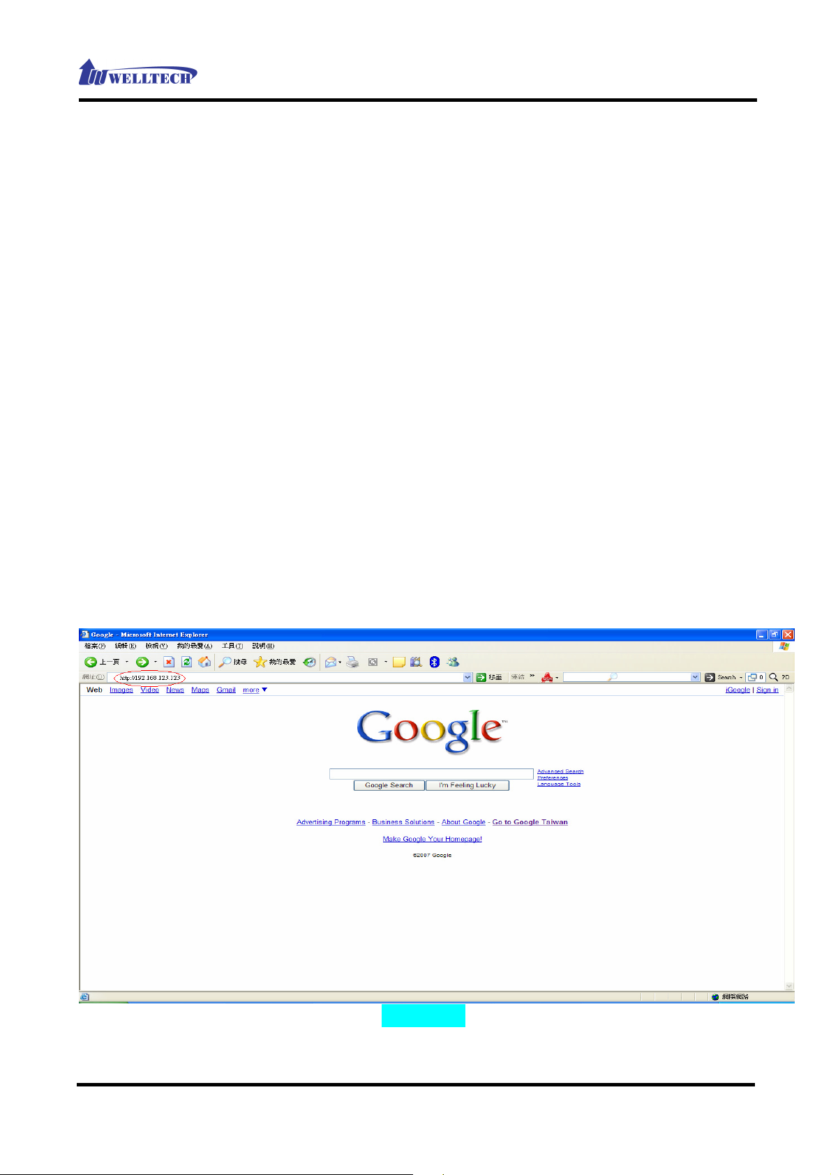
2. Open your WEB browser and key in the IP address of the gateway
(http://192.168.123.123) in the Address box (see figure 1).
(Figure 1)
Copyright © 2007 Welltech Computer Co., Ltd. All right reserved.
6
Page 8

WellGate 2626 User Manual EN-V1.00
3. You will see a pop-up window requesting username and password before you
can login to the web configuration menu. Username is “root” while password is
blank “ “ (see figure 2).
(Figure 2)
3. You will enter the main page of the web configuration interface after you
keyed in the username and password correctly (see figure 3).
(Figure 3)
Copyright © 2007 Welltech Computer Co., Ltd. All right reserved.
7
Page 9

WellGate 2626 User Manual EN-V1.00
Device
The following instructions will explain the configurations for setting up the WAN
port of the WG2626. There are in total three methods of connections: Static IP,
DHCP and PPPoE. (see figure 4)
Device_WAN Setting
(Figure 4)
The table shown below describes the configuration items for 3 connection types
of network (Static IP, DHCP and PPPoE).
Copyright © 2007 Welltech Computer Co., Ltd. All right reserved.
8
Page 10

WellGate 2626 User Manual EN-V1.00
Device_WAN Setting
Item Description Static IP DHCP PPPoE
Connected mode Select the connection method
for the WAN port of the
WG2626, you can choose the
following:
V V V
Static IP
DHCP
PPPoE
Current IP Address Show current IP address V V V
DNS server mode Select the DNS behavior, you
can choose the following:
Auto
Manual
“DNS auto” will retrieve the
V V V
DNS information sent from
the DHCP server.
“Manual” will look at the
specified Primary and
Secondary DNS address.
Primary DNS address Specify the address of the
Primary DNS.
Secondary DNS
address
Specify the address of the
Secondary DNS.
WAN Link Speed Select the connection speed
for the WAN port of the
WG2626, you can choose the
following:
Auto
100M
10M
HTTP port for WEB
management
Specify the port number for
WEB management, the
allowable range is
V V V
V V V
V V V
V V V
80,1024~65535.
IP address Specify the IP address. V
Subnet mask Specify the subnet mask. V
Copyright © 2007 Welltech Computer Co., Ltd. All right reserved.
9
Page 11

WellGate 2626 User Manual EN-V1.00
Device_WAN Setting
Item Description Static IP DHCP PPPoE
Default gateway Specify the IP address of the
default gateway.
Remote access
restriction
Restricts/Blocks users
connecting to the WAN port’s
IP remotely, you can
Enable/Disable this option.
PPPoE userID Specify the username of the
PPPoE account
PPPoE password Specify the password
associated to the PPPoE
account above.
Reboot after remote
host disconnection
When the remote host
(PPPoE) fails, the gateway
will retry 3 times to
reconnect, if there is no reply
from the remote host within 3
V
V V V
V
V
V
tries, then the gateway will
reboot. You can
Enable/Disable this option.
MTU It is used to specified the max
transmission unit when using
PPPoE. The default value is
1492 and it could be smaller
is you are encounter the
PPPoE connecting issues.
V
Copyright © 2007 Welltech Computer Co., Ltd. All right reserved.
10
Page 12

Device_WAN Setting --Static IP
WellGate 2626 User Manual EN-V1.00
(Figure 5)
1. When you select the “Static IP” mode, please Specify the marked item shown
as the figure 5.
2. Press the “Apply” button (at the bottom) after you finish to save changes.
(Figure 6)
3. Press the “Reboot” button to apply the changes.(see figure 6)
Copyright © 2007 Welltech Computer Co., Ltd. All right reserved.
11
Page 13

WellGate 2626 User Manual EN-V1.00
Device_WAN Setting --DHCP
(Figure 7)
1. If you select the “DHCP” mode, please Specify the marked item shown as the
figure 7.
2. Press the “Apply” button (at the bottom) after you finish to save changes.
3. Press the “Reboot” button to apply the changes.
Device_WAN Setting --PPPoE
(Figure 8)
1. When you select the “PPPoE” mode, please Specify the marked item shown as
Copyright © 2007 Welltech Computer Co., Ltd. All right reserved.
12
Page 14

WellGate 2626 User Manual EN-V1.00
the figure 8.
2. Press the “Apply” button (at the bottom) after you finish to save changes.
3. Press the “CANCEL” button (next to the Apply button) to clear the values in
the page.
4. Press the “Reboot” button to apply the changes.
Device_Login
(Figure 9)
1. You can change the login password of WG2626, as the figure 9 shown. If you
set the new password, please remember it and use the new password when
the device is rebooted.
2. Press the “Apply” button (at the bottom) after you finish to save changes.
3. Press the “Reboot” button to apply the changes.
Copyright © 2007 Welltech Computer Co., Ltd. All right reserved.
13
Page 15

WellGate 2626 User Manual EN-V1.00
Service
To initial the VoIP service, you will need a SIP account provided by the SIP Proxy
you are registered with. To configure the relevant SIP settings, please refer to
the instructions step by step.
Service_Preference
(Figure 10)
1. In the “Service_Preference” section (see figure 10), you can specify the
“Codec Policy” by your requirement of environment. The priority of codecs for
the three types are shown below:
Bandwidth : If your Internet Connection had very limited bandwidth,
please select bandwidth priority. The codec priority will be G.723, G.729
and G.711.
Regular : For most of case or unknown environment, please select
Regular. The codec priority will be G729, G.723 and G.711.
Quality : If your network is only running on the LAN environment or
have no any concerns of bandwidth, please select Quality. The codec
priority will be G.711, G.729 and G.723
The default setting is “Regular”.
2. Press the “Apply” button (at the bottom) after you finish to save changes.
3. Press the “Reboot” button to apply the changes.
Copyright © 2007 Welltech Computer Co., Ltd. All right reserved.
14
Page 16

Service_Extension Line
(Figure 11)
WellGate 2626 User Manual EN-V1.00
In the “Service_Extension Line Setting” section (see figure 11), you can set the
operator priority of the extensions for incoming call. The detail instruction
explained below:
Caller ID Enable or Disable the Caller ID
Sending to Telephone Set. You have to
use Caller ID phone in order to display
the caller information. If unsure,
please set to Disable.
Caller ID Type Specify the caller ID Type of your
phone set : DTMF, FSK(Bellcore),
ETSI(Before Ring) or ETSI(Between
Ring)
Operator Ring Mode Specify the Operator Ring Mode:
1. “Priority Ring” : The operator will be
hunted based on the priority
defined in extension. If the higher
priority’s extension is busy, the call
will automatically hunt to second
one and so on.
2. Simultaneous Ring: Parallel Ring all
priority of operators’ extension,
exclude those extension’s operator
set to ”NA”.
Copyright © 2007 Welltech Computer Co., Ltd. All right reserved.
15
Page 17

WellGate 2626 User Manual EN-V1.00
Ring Time Specify ring time : 5~60 sec. It is used
for priority hunting which define how
long the system will think the ringing
operator is not able to take the call and
hunt to next. The default value is 20 to
40 seconds.
Operator Short Code Specify the short code of Operator (eg.
9 or 0). The default value is 9.
TEL 1 ~TEL6
Line Number Specify the extension number
Operator Specify the Operator priority of
incoming call; you can set the priority
from 1st to 6th or “NA” for extension.
TEL1 and TEL2 are the default
operators.
Forward Condition Specify the extensions forward
condition, you can choose the
following:
Disable
UNCONDITIONAL
BUSY
NO ANSWER
BUSY + NO ANSWER
Forward TEL Specify the forward extension number
1. Press the “Apply” button (at the bottom) after you finish to save changes.
2. Press the “Reboot” button to apply the changes.
Copyright © 2007 Welltech Computer Co., Ltd. All right reserved.
16
Page 18

Service_PSTN Line
WellGate 2626 User Manual EN-V1.00
(Figure 12)
In the “Service_PSTN Line ” section (see figure 12), you can define the routing
rule of incoming/outgoing PSTN call, the detail information please refer to the
table below.
PSTN Line Setting
PSTN incoming Route Specify the PSTN incoming call routing
rule, via IVR or direct to operator.
PSTN Call Notice If you Select “Yes”, system will send a
PSTN call notice tone before dialing
when the SIP trunk (Ethernet) is fail.
Select “No”, this feature will be
disabled.
Disconnect Tone
Country Template Specify the location of WG2626, Click
the “Use” icon when you select the
correct country. System will use the
selected country’s PSTN tone to
become the active value. You can
modify it if necessary.
Route Setting Those prefix defined here, will be route
to PSTN no matter VOIP is active or
not.
Copyright © 2007 Welltech Computer Co., Ltd. All right reserved.
17
Page 19

WellGate 2626 User Manual EN-V1.00
1. Press the “Apply” button (at the bottom) after you finish to save changes.
2. Press the “Reboot” button to apply the changes.
Service_SIP Trunk
(Figure 13)
In the “Service_SIP Trunk ” section (see figure 13), you have to set the SIP
account for VOIP service.
SIP Trunk Setting
SIP incoming Route Specify the SIP incoming call routing
rule, via IVR or direct to operator.
Route to Operator if IVR busy If you select IVR mode for SIP
incoming call, system will route the call
to operator automatically when IVR is
busy.
Set “Yes” to enable.
Set “No” to disable.
Secondary SIP Proxy Server Enable/Disable Secondary SIP Proxy
Server
SIP Account Setting
Line Number Specify the SIP line number
(This item is essential for VOIP
service)
User ID Specify SIP account
Copyright © 2007 Welltech Computer Co., Ltd. All right reserved.
18
Page 20

WellGate 2626 User Manual EN-V1.00
(This item is essential for VOIP
service)
Password Set password of SIP account
(This item is essential for VOIP
service)
Primary SIP Proxy Server Specify the IP address
(This item is essential for VOIP
service)
Primary SIP Proxy Port Specify the port number, the default
port number is 5060
(This item is essential for VOIP
service)
Primary SIP Domain Specify the Domain name
Primary Outbound Proxy Server Specify the IP address
Primary Outbound Proxy Port Specify the port number, the default
port number is 5060
Secondary SIP Proxy Server If you “Enable” the Secondary SIP
Proxy Server, please set the IP address
Secondary SIP Proxy Port Specify the port number, the default
port number is 5060
Secondary SIP Domain Specify the secondary SIP Domain
name
Secondary Outbound Proxy Server Specify the IP address of Secondary
Outbound Proxy Server
Secondary Outbound Proxy Port Specify the port number, the default
port number is 5060
1. Press the “Apply” button (at the bottom) after you finish to save changes.
2. Press the “Reboot” button to apply the changes.
Copyright © 2007 Welltech Computer Co., Ltd. All right reserved.
19
Page 21

IVR Greeting
(Figure 14)
WellGate 2626 User Manual EN-V1.00
(Figure 15)
In the “Service_IVR Greeting ” section (see figure 14,15), you can customize the
IVR greeting prompts by uploading those files into Wellgate 2626.
Greeting Type The default contents of greeting are
shown below:
1. Welcome : Thank you for calling
2. Menu: Please dial extension
number or 9 for operator
3. Busy: The extension you dialed is
busy
4. No Answer: The extension you
Copyright © 2007 Welltech Computer Co., Ltd. All right reserved.
20
Page 22

WellGate 2626 User Manual EN-V1.00
dialed is no answer
5. Error: Sorry, this extension number
does not exist
6. Transferring: Please wait
7. Bye: Please try later, thank you
8. Hold:(Play Music)
If you want to change the contents,
please be sure the voice format is
711u,8k,8bits,raw file.
Upload file If you want to upload the greeting file,
please select the greeting type, specify
the file path and file name, and then
click the “Upload” icon.
1. Press the “Reboot” button to apply the changes.
Service_Status
(Figure 16)
In the “Service_Status” section (see figure 16), Display the status of Network,
S/W version and line.
Network Status
Copyright © 2007 Welltech Computer Co., Ltd. All right reserved.
21
Page 23

WellGate 2626 User Manual EN-V1.00
Connection mode Displays the current connection mode.
Current IP address Displays the current IP address of the
WAN port.
Subnet mask Displays the current subnet mask’s IP.
Default gateway Displays the current default gateway’s
IP.
Primary DNS address Displays the current primary DNS
address.
Second DNS address Displays the current secondary DNS
address.
WAN MAC Displays the MAC address of the WAN
port.
Version Information
Boot version Displays the current boot version
loaded on the WG2626.
Post version Displays the current post version
loaded on the WG2626.
Application version Displays the current application
version loaded on the WG2626.
Line Status
Item Displays the corresponding port
number.
Type Displays the port type (FXS,FXO)of the
corresponding port number.
Line Number Displays the line number
Status Displays the status of the port.
Register Displays the registration status of the
corresponding port number.
Copyright © 2007 Welltech Computer Co., Ltd. All right reserved.
22
Page 24

WellGate 2626 User Manual EN-V1.00
Management
Management_Backup-Restore Setting
(Figure 17)
Export File Click the “Export” button to export
“user.cfg” data
Import File Specify the file path and file name to
Import the configuration data.
1. After import data, press the “Reboot” button to apply the changes.
Management_Upgrade Firmware
(Figure 18)
Download mode Select the connection method to
update the WG2626’s firmware, you
can choose the following:
Copyright © 2007 Welltech Computer Co., Ltd. All right reserved.
23
Page 25

WellGate 2626 User Manual EN-V1.00
TFTP
FTP
TFTP/FTP server IP address Specify the TFTP/FTP server’s IP
address.
FTP login If you select FTP download mode,
please specify the login user
name/password for the FTP server.
Target file name Specify the target file name for the
firmware.
Http Upload Specify the location of the firmware for
uploading through Http.
Updating the firmware by FTP
(Figure 19)
1. Under Management => Upgrade firmware (see figure 19) Select FTP mode in
the drop down list.
2. Key in the IP address, login name, password of your FTP server and specify
the correct filename of the firmware.
3. Press the Start button (next to the Target file name text box) to execute the
upgrade process.
4. Please wait while the device updates itself with the firmware.
5. After the update process is finish, you will be taken to a web page indicating
that it was successful.
6. Press the “Reboot” button to apply the changes.
Copyright © 2007 Welltech Computer Co., Ltd. All right reserved.
24
Page 26

WellGate 2626 User Manual EN-V1.00
Updating the firmware by TFTP
(Figure 20)
1. First, download the TFTP program from our website
http://www.welltech.com/support/utility.htm. Unzip the TFTP to a directory
that you desire in your hard drive and execute the TFTP program. Make sure
that the TFTP program points to the directory of where your firmware is
stored. Now, leave the TFTP program running and switch back to the
WG2626 web configuration interface.
2. Under Management => Upgrade firmware (see figure 20) select TFTP mode in
the drop down list.
3. Key in the IP address of the TFTP server and specify the correct filename of
the firmware.
4. Press the Start button (next to the Target file name text box) to execute the
upgrade process.
5. Please wait while the device updates itself with the firmware.
6. After the update process is finish, you will be taken to a web page indicating
that it was successful (see figure below).
7. Press the “Reboot” button to apply the changes.
Copyright © 2007 Welltech Computer Co., Ltd. All right reserved.
25
Page 27

WellGate 2626 User Manual EN-V1.00
Updating the firmware by HTTP
(Figure 21)
1. Under Management => Upgrade firmware web menu (see figure 21), specify
the location of the firmware by clicking the Browse button next to the Http
Upload text box.
2. You will be prompted with a window requesting the location of the firmware.
3. Locate the firmware that is stored in your hard drive.
4. Once located, click the Open button.
5. Back in the web configuration menu, press the Start button (next to the Http
Upload’s browse button) to execute the upgrade process.
6. Please wait while the device updates itself with the firmware.
7. After the update process is finish, you will be taken to a web page indicating
that it was successful.
Note: For consistency, it is recommended to reload default setting every time
you update the firmware on the WG2626. However, you will lose all the settings
configured on the WG2626 except Network configuration. For more details on
reload default setting, please refer to the next page below.
Copyright © 2007 Welltech Computer Co., Ltd. All right reserved.
26
Page 28

WellGate 2626 User Manual EN-V1.00
Management_Reset to Default
(Figure 22)
Users can restore back to factory default settings using this feature (see figure
22). The password of the account and the network configurations are the things
that will not be changed when this feature is executed.
Rebooting the system
(Figure 23)
Executing this function will reboot the whole system, when configuration changes
are made to the device, it needs to be rebooted for the changes to take effect
(see figure 23).
Copyright © 2007 Welltech Computer Co., Ltd. All right reserved.
27
 Loading...