


 Loading...
Patient Monitor
Service Manual
French Version
German Version
Spanish Version
Italian Version
SYSTOLIC
SpO2 |
|
(mmHg) |
|
PULSE |
(BPM) |
|
|
%
TEMPERATURE |
Pulse |
|
Volume |
||
|
Tone |
|
Charging |
Select |
|
Alarm |
||
Low |
||
Battery |
|
|
CYCLE |
|
|
|
Set |
|
Review |
|
|
Auto |
|
|
|
Silence |
Operator’s Manual
C A U T I O N
United States Federal Law restricts this device to
sale by or on the order of a licensed health care practitioner.
|
TABLE OF CONTENTS |
|
Section I - Introduction |
|
|
1. |
About the Operator Manual .............................................................................................. |
1 |
2. |
Product Overview ................................................................................................................ |
1 |
3. |
Indications/Contraindications For Use ............................................................................ |
2 |
4. |
Special Features .................................................................................................................... |
2 |
5. |
Supplies and Accessories ................................................................................................ |
3-5 |
Section II - Functions & Specifications |
|
|
1. |
Blood Pressure Operating Modes .................................................................................. |
7-8 |
|
a. Max/Min Blood Pressure and Pulse Ranges ...................................................... |
7 |
|
b. Blood Pressure Manual Mode ................................................................................ |
8 |
|
c. Blood Pressure Automatic Mode .......................................................................... |
8 |
2. |
Temperature Operating Modes .................................................................................... |
9-10 |
|
a. Max/Min Temperature Ranges.............................................................................. |
9 |
|
b. Temperature Normal Mode.................................................................................... |
9 |
|
c. Temperature Monitor Mode.................................................................................. |
10 |
3. |
SpO2 Operating Mode.................................................................................................. |
10-11 |
|
a. Max/Min SpO2 Ranges ........................................................................................ |
11 |
|
b. SpO2 Monitor Mode .............................................................................................. |
11 |
4. |
Pulse Rate Feature .............................................................................................................. |
12 |
|
a. Max/Min Pulse Rate Ranges................................................................................ |
12 |
5. |
Performance Specifications.......................................................................................... |
13-14 |
6. |
Technical Specifications................................................................................................ |
14-15 |
|
a. Mechanical Specifications .................................................................................... |
14 |
|
b. Electrical Specifications ........................................................................................ |
15 |
|
c. Environmental Specifications .............................................................................. |
15 |
|
d. Transportation/Storage Conditions.................................................................... |
15 |
Section III - System Installation |
|
|
1. |
Unpacking Checklist .................................................................................................... |
16-17 |
2. |
Controls, Indicators and Connections........................................................................ |
18-22 |
|
a. Front Panel ........................................................................................................ |
18-20 |
|
b. Side & Rear Panel Connections ...................................................................... |
21-22 |
3. |
Set Up Procedure .......................................................................................................... |
22-29 |
|
a. Blood Pressure Hose & Cuff Connections .................................................... |
22-23 |
|
b. Temperature Probe Connection .......................................................................... |
24 |
|
c. SpO2 Sensor Connection ...................................................................................... |
25 |
|
d. AC Power Connection .......................................................................................... |
26 |
|
e. Charging the Battery.............................................................................................. |
26 |
|
f. Setting Up the Printer ...................................................................................... |
27-28 |
|
g. Changing the Date and Time Setting .................................................................. |
29 |
4. |
Safety Warnings and Cautions.................................................................................... |
30-32 |

WELCH ALLYN VITAL SIGNS MONITOR |
OPERATOR MANUAL |
||
Section IV - Operating Procedures |
|
|
|
1. |
Power On/System Check Procedure ............................................................................ |
|
34 |
2. |
Choosing Operating Modes.............................................................................................. |
|
34 |
3. |
Setting the Programmable Alarms ............................................................................ |
|
35-38 |
|
a. Blood Pressure - High Systolic Limit .................................................................. |
|
35 |
|
b. Blood Pressure - Low Systolic Limit .................................................................. |
|
36 |
|
c. Blood Pressure - High Diastolic Limit ................................................................ |
|
36 |
|
d. Blood Pressure - Low Diastolic Limit ................................................................ |
|
37 |
|
e. Pulse Rate - High Limit ........................................................................................ |
|
37 |
|
f. Pulse Rate - Low Limit .......................................................................................... |
|
38 |
|
g. SpO2 - Low Limit .................................................................................................. |
|
38 |
4. |
Temperature Measurement Range Indicators .............................................................. |
|
39 |
5. |
Alarm Indications and Interpretation ............................................................................ |
|
40 |
6. |
Setting the Default Inflation Pressure Preset Level...................................................... |
|
41 |
7. |
Blood Pressure Cuff Selection Criteria .......................................................................... |
|
42 |
8. |
Positioning the Blood Pressure Cuff .............................................................................. |
|
43 |
9. |
Manual Mode Blood Pressure ........................................................................................ |
|
43 |
10. Automatic Mode Blood Pressure .............................................................................. |
|
44-45 |
|
11. Reviewing Information from Prior Cycles .................................................................... |
|
46 |
|
|
a. “Erase Data” Function .......................................................................................... |
|
46 |
12. Selecting the Temperature Scale...................................................................................... |
|
47 |
|
13. Selecting Temperature Operation Mode ........................................................................ |
|
48 |
|
14. Taking Oral Temperature ............................................................................................ |
|
49-50 |
|
15. Taking Axillary Temperature...................................................................................... |
|
51-52 |
|
16. Taking Rectal Temperature ........................................................................................ |
|
52-53 |
|
17. SpO2 Operation Mode ................................................................................................ |
|
53-56 |
|
|
a. Using the Finger Clip Sensor................................................................................ |
|
54 |
|
b. Other Sensors.......................................................................................................... |
|
55 |
|
c. Taking an SpO2 Measurement.............................................................................. |
|
55 |
|
d. Using the SpO2 Pulse Tone .................................................................................. |
|
56 |
18. Printer Operation/Symbols ............................................................................................ |
|
57 |
|
|
a. Printing Options: Batch Print or Streaming Print Mode .................................. |
|
58 |
19. Using the RS232 Computer Interface ............................................................................ |
|
58 |
|
|
a. “Nurse Call” Interface .......................................................................................... |
|
58 |
20. Mean Arterial Pressure (MAP)/Data Send Mode/Data Stream Mode |
....................59 |
||
Section V - Troubleshooting/Maintenance/Calibration |
|
|
|
1. |
Troubleshooting: Error Indications and Interpretation.......................................... |
|
60-62 |
2. |
Troubleshooting: General Guide to Problems and Corrective Actions ................ |
62-64 |
|
3. |
Maintenance .................................................................................................................. |
|
65-66 |
|
a. Cleaning .................................................................................................................. |
|
65 |
|
b. Storage .................................................................................................................... |
|
65 |
|
c. Battery Removal and Replacement...................................................................... |
|
66 |

WELCH ALLYN VITAL SIGNS MONITOR |
OPERATOR MANUAL |
|
4. |
Calibration...................................................................................................................... |
67-68 |
|
a. Blood Pressure Calibration Check.................................................................. |
67-68 |
|
b. Temperature Calibration Check .......................................................................... |
68 |
|
c. SpO2 Calibration Check ........................................................................................ |
68 |
Section VI - Warranty and Service Information |
|
|
1. |
Warranty Information ........................................................................................................ |
70 |
2. |
Service Information ...................................................................................................... |
70-72 |
|
a. Service Policy .......................................................................................................... |
70 |
|
b. Technical Assistance/Service Centers............................................................ |
71-72 |
|
c. Service Manual/Spare Parts ................................................................................ |
72 |
|
d. Service Loaners ...................................................................................................... |
72 |
Appendix A: Nonin® Brand SpO2 Sensors
Appendix B: Nellcor Puritan BennettTM Brand SpO2 Sensors Appendix C: Mounting Accessories & Assembly Instructions Appendix D: Nurse Call Interface Wiring Diagram

WELCH ALLYN VITAL SIGNS MONITOR |
OPERATOR MANUAL |
|
|
SECTION I
INTRODUCTION
1.About the Operator Manual
2.Product Overview
3.Indications/Contraindications For Use
4.Special Features
5.Supplies and Accessories

WELCH ALLYN VITAL SIGNS MONITOR |
OPERATOR MANUAL |
|
|
I. 1 ABOUT THE OPERATOR MANUAL
The operator manual is designed to help you understand the capabilities and operation of your Welch Allyn Vital Signs Monitor. The manual has six tabbed sections and the first page of each section outlines the contents so you can readily find the information you need.
The information included in this manual is inclusive of all options available with the Welch Allyn Vital Signs Monitor (ie. SpO2, Temperature and Printer). The applicability of some sections of this operator manual will depend on the configuration of your particular unit.
The first two sections, INTRODUCTION and FUNCTIONS & SPECIFICATIONS introduce you to the product, its applications and its capabilities. The next two sections, SYSTEM INSTALLATION and OPERATING PROCEDURES takes you step by step through the installation and functional operation of the monitor in a logical sequence. The final two sections, TROUBLESHOOTING/MAINTENANCE/CALIBRATION and WARRANTY AND SERVICE INFORMATION are resources to offer troubleshooting or other special help as needed.
This information is intended as a comprehensive guide to the operation of the Welch Allyn Vital Signs Monitor. To achieve satisfactory results, the operator should read this manual thoroughly before attempting to use the monitor. A quick reference operator's guide is provided on the side of the monitor as a convenient reference for experienced operators.
I. 2 PRODUCT OVERVIEW
The Welch Allyn Vital Signs Monitor is designed to non-invasively and automatically measure systolic and diastolic blood pressure, pulse rate, temperature and oxygen saturation (SpO2) for adult and pediatric patients. THE WELCH ALLYN VITAL SIGNS MONITOR IS NOT INTENDED TO BE USED ON NEONATAL PATIENTS. All blood pressure, pulse, temperature and SpO2 values are displayed on large, easy-to-read displays, and may be printed via an integrated thermal printer, as desired.
The rechargeable battery and wide variety of mounting accessories make the Welch Allyn Vital Signs Monitor convenient for many locations. The operator may choose any combination of simultaneous measurement modalities. This flexibility, combined with features such as programmable alarms and automatic blood pressure cycles, makes the Welch Allyn Vital Signs Monitor ideal for a wide variety of patient monitoring needs.
The Welch Allyn Vital Signs Monitor is intended for use in a wide variety of health care settings. This includes hospital departments, as well as patient transport within the hospital environment. The Welch Allyn Vital Signs Monitor is also intended for use in alternate care settings, such as physician offices, freestanding ambulatory care and surgery centers, health clinics and nursing homes. The Welch Allyn Vital Signs Monitor may also be used during patient transport within any of these alternate care environments.
The Welch Allyn Vital Signs Monitor is not intended for the monitoring of patients during transport external to the health care environment (eg. ambulance, helicopter transport). The Welch Allyn Vital Signs Monitor is not intended for use in environments which are not supervised by a health care practitioner.
1

WELCH ALLYN VITAL SIGNS MONITOR |
OPERATOR MANUAL |
|
|
I. 3 INDICATIONS/CONTRAINDICATIONS FOR USE
The Welch Allyn Vital Signs Monitor is intended for monitoring of blood pressure, pulse rate, temperature and oxygen saturation (SpO2) of adult and pediatric patients. The device is not designed, sold or intended for use except as indicated.
THE WELCH ALLYN VITAL SIGNS MONITOR IS NOT INTENDED TO BE USED ON NEONATAL PATIENTS.* To ensure pediatric blood pressure accuracy and safety, note that the Welch Allyn small cuff (5200-03) is the SMALLEST CUFF approved for use with young children and infants. The circumference of the child’s arm must fit within the range markings on the cuff.
* Welch Allyn defines neonates as children 28 days or less of age if born at term (37 weeks gestation or more); otherwise, up to 44 gestational weeks. This definition comes from the AAMI SP10 1992 standard.
The monitor should not be used on patients who are linked to heart/lung machines.
I. 4 SPECIAL FEATURES
The following special features enhance the use of the Welch Allyn Vital Signs Monitor:
Choice of Measurement Modalities
Non-invasive blood pressure, temperature, and SpO2 measurements may be made independently or simultaneously.
Operator Selectable BP Measurement Intervals
Automatically takes BP measurements at intervals from 1 to 90 minutes. Special "STAT" mode allows continuous blood pressure measurements for up to 15 minutes.
Programmable Alarms
Both visual and audible alarms indicate readings outside of operator programmable high/low limits, and also indicate system hardware/software problems.
Non-Invasive, Oscillometric BP
Eliminates the risks associated with invasive monitoring, with no need for microphones or external transducers.
Prior Data Recall
Measurement data from up to 99 previous determinations is available at the touch of a button.
Operator-Friendly Results
Large, easy-to-read LED displays are complemented by an integrated thermal printer.
AC or Self-Contained Battery Power
The Welch Allyn Vital Signs Monitor is conveniently available in many locations, for a variety of monitoring needs, including interdepartmental transport within the facility.
2

WELCH ALLYN VITAL SIGNS MONITOR |
OPERATOR MANUAL |
|
|
I. 5 SUPPLIES AND ACCESSORIES
BLOOD PRESSURE ACCESSORIES AND SUPPLIES - LATEX FREE
5200-01 |
Cuff Assembly: |
Adult (cuff, bladder and connector) |
||
5200-02 |
Cuff Assembly: |
Large Adult (cuff, bladder and connector) |
||
5200-03 |
Cuff Assembly: |
Small (cuff, bladder and connector) |
||
5200-10 |
Cuff Assembly: |
Extra-Large Adult (cuff, bladder and connector) |
||
5082-59 |
Cuff: |
Adult |
|
|
5082-61 |
Cuff: |
Large Adult |
|
|
5082-63 |
Cuff: |
Small |
|
|
5082-64 |
Cuff: |
Extra-Large Adult |
||
5200-04 |
Bladder: |
Adult (includes connector) |
||
5200-05 |
Bladder: |
Large Adult (includes connector) |
||
5200-06 |
Bladder: |
Small (includes connector) |
||
5200-11 |
Bladder: |
Extra-Large Adult (includes connector) |
||
5200-07 |
Coiled Pressure Hose (8ft.) (2.4M) Note: One additional hose may be |
|||
|
connected to provide extended length. All appropriate connectors are included. |
|||
5200-12 |
Straight Pressure Hose (8ft.) (2.4M) |
|||
5200-08 |
Calibration T-Connector |
|||
TEMPERATURE ACCESSORIES AND SUPPLIES
5200-20 Oral Probe: (9ft.) (2.7M)
5200-22 Rectal Probe: (9ft) (2.7M)
05031-101 Disposable Probe Covers (1000 covers, packaged 25/box)
06137-000 Temperature Calibration Key
01800-210 Model 9600 Temperature Calibration Kit, 110v
NONIN® PULSE OXIMETRY ACCESSORIES AND SUPPLIES
5200-40 |
Finger Clip Sensor with 9ft. (2.7M) cable |
|
5200-54 |
Finger Clip Sensor with 3ft. (0.9M) cable |
|
5200-41 |
Ear Clip Sensor |
|
5200-42 |
Flex Sensor |
|
5200-44 |
Reflectance Sensor |
|
5200-45 |
Reflectance Sensor Holder (10) |
|
5200-46 |
SpO2 Adult Finger Flexiform Sensors (10) |
|
5200-47 |
SpO2 Pediatric Finger Flexiform Sensors (10) |
|
5200-50 |
SpO2 Sensor Attachment Tape |
|
5200-51 |
SpO2 |
Hydrogel Tape Strips |
5200-52 |
SpO2 |
Extension Cable (3ft) (0.9m) |
5200-53 |
SpO2 |
Finger Phantom Calibration Kit |
5200-55 |
SpO2 |
Extension Cable (9ft) (2.7m) |
3

WELCH ALLYN VITAL SIGNS MONITOR |
OPERATOR MANUAL |
|
|
NELLCOR PURITAN BENNETTTM PULSE OXIMETRY ACCESSORIES
AND SUPPLIES
DS-lOOA |
DURASENSOR® Adult Oxygen Transducer |
EC-8 |
Extension Cable (8 ft.) |
D-YS |
DURA-Y® Oxygen Transducer (1 sensor, 40 wraps) |
D-YSE |
Ear Clip, (use with Dura-Y sensor) |
D-YSPD |
PediCheckTM Pediatric Spot-Check (use with Dura-Y sensor) |
D-25 |
OXISENSOR® II Adult Digit Oxygen Transducer (case of 24) |
D-25L |
OXISENSOR® II Adult Digit Oxygen Transducer, long cable (case of 24) |
D-20 |
OXISENSOR® II Pediatric Oxygen Transducer (case of 24) |
I-20 |
OXISENSOR® II Infant Digit Oxygen Transducer (case of 24) |
R-15 |
OXISENSOR® Adult Nasal Oxygen Transducer (case of 24) |
OXICLIQ® A Adult Oxygen Transducer, use with OC-3 cable (case of 24) |
|
OXICLIQ® P Pediatric Oxygen Transducer, use with OC-3 cable (case of 24) |
|
OC-3 |
OXICLIQ® Sensor Cable |
OXI-A/N |
OXIBAND® Adult/Neonatal Oxygen Transducer (1 sensor, 50 wraps) |
OXI-P/I |
OXIBAND® Pediatric/Infant Oxygen Transducer (1 sensor, 50 wraps) |
RS-10 |
Reflectance Oxygen Transducer (6 sensors, 6 headbands) |
SRC-2 |
Portable Oximetry Tester |
MOUNTING ACCESSORIES AND SUPPLIES
5200-60 COMPLETE MOBILE STAND UNIT includes: Accessory Pack
Large Basket
Pole and Base Assembly
Transformer Mounting Kit
Recommended for Models: 52STP, 52STO, 52OTP, 52OTO, 52NTP, 52NTO
5200-61 MODIFIED MOBILE STAND UNIT includes: Large Basket
Pole and Base Assembly
Transformer Mounting Kit
Recommended for Models: 52OOO, 52OOP, 52SOO, 52SOP, 52NOO, 52NOP
5200-62 COMPLETE WALL MOUNT UNIT includes Accessory Pack
Large Basket
Wall Mount Bracket Transformer Mounting Kit
Recommended for Models: 52STP, 52STO, 52OTP, 52OTO, 52NTP, 52NTO
5200-63 MODIFIED WALL MOUNT UNIT includes: Large Basket
Wall Mount Bracket Transformer Mounting Kit
Recommended for Models: 52OOO, 52OOP, 52SOO, 52SOP, 52NOO, 52NOP
4
WELCH ALLYN VITAL SIGNS MONITOR |
OPERATOR MANUAL |
|
|
|
|
5200-64 |
COMPLETE IV POLE MOUNT UNIT includes: |
|
|
Accessory Pack |
|
|
Large Basket |
|
|
IV Pole Mount Bracket |
|
|
Transformer Mounting Kit |
|
|
Recommended for Models: 52STP, 52STO, 52OTP, 52OTO, 52NTP, 52NTO |
|
5200-65 |
MODIFIED IV POLE MOUNT UNIT includes: |
|
|
Large Basket |
|
|
IV Pole Mount Bracket |
|
|
Transformer Mounting Kit |
|
|
Recommended for Models: 52OOO, 52OOP, 52SOO, 52SOP, 52NOO, 52NOP |
|
5200-66 |
COMPLETE BED-RAIL MOUNTING UNIT includes: |
|
|
Accessory Pack |
|
|
(2) Bed-Rail Brackets |
|
|
Recommended for Models: 52STP, 52STO, 52OTP, 52OTO, 52NTP, 52NTO |
|
5200-67 |
MODIFIED BED-RAIL MOUNTING UNIT includes: |
|
|
(2) Bed-Rail Brackets |
|
|
Recommended for Models: 52OOO, 52OOP, 52SOO, 52SOP, 52NOO, 52NOP |
|
5200-68 |
Cuff Clip |
|
5200-69 |
Accessory Pack |
|
5200-70 |
Anti-Theft Kit for Mounting Devices |
|
MISCELLANEOUS SUPPLIES
7052-25 Printer Paper (6 rolls/box)
5200-84 Lead-acid Battery
5200-85E Operator Manual
5200-145E Service Manual
5200-88 Plastic Monitor Covers (pack of 5)
5200-100 Welch Allyn Vital Signs Monitor Carrying Case
5200-101 AC Power Transformer (desktop transformer, line cord not included) - North AmericanVersion
5200-102 AC Power Transformer (desktop transformer, line cord not included) - European Version
5200-103 AC Power Transformer (desktop transformer, line cord not included) - United Kingdom Version
5200-106 Transformer Mounting Kit (for use with the desktop transformer) 5200-110 Line Cord (United States/Canada/Japan version)
5200-111 Line Cord (European version)
5200-112 Line Cord (United Kingdom version)
5200-113 Line Cord (Australian version)
5200-114 Line Cord (Swiss version)
5200-115 Line Cord (South American version)
5

WELCH ALLYN VITAL SIGNS MONITOR |
OPERATOR MANUAL |
|
|
SECTION II
FUNCTIONS AND SPECIFICATIONS
1.Blood Pressure Operating Modes
a.Max/Min Blood Pressure and Pulse Ranges
b.Blood Pressure Manual Mode
c.Blood Pressure Auto Mode
2.Temperature Operating Modes
a.Max/Min Temperature Ranges
b.Temperature Normal Mode
c.Temperature Monitor Mode
3.SpO2 Operating Mode
a.Max/Min SpO2 Ranges
b.SpO2 Monitor Mode
4.Pulse Rate Feature
a.Max/Min Pulse Rate Ranges
5.Performance Specifications
6.Technical Specifications
a.Mechanical Specifications
b.Electrical Specifications
c.Environmental Specifications
d.Transportation/Storage Conditions
6

WELCH ALLYN VITAL SIGNS MONITOR |
OPERATOR MANUAL |
|
|
II. 1. BLOOD PRESSURE OPERATING MODES
When a blood pressure measurement cycle is initiated, the cuff will automatically inflate to the default pressure level.
The cuff will immediately begin to deflate in a stepped fashion and will determine systolic pressure and diastolic pressure from the pulses sensed by the cuff at various pressure levels. This is the oscillometric method of non-invasive blood pressure monitoring.
Blood pressure measurements may be initiated manually, or automatically at time intervals determined by the user.
At the completion of a measurement cycle the systolic and diastolic pressures are displayed. If the Monitor is in Automatic Mode, the measured values are kept on display until the next BP measurement is initiated. When not in Automatic Mode, the measured values are displayed for two minutes, after which time the display screen is blanked. The most recent BP measurement may be recalled by pressing the REVIEW button.
When in Automatic Mode, if the unit is unable to determine the systolic or diastolic value, the measurement will be automatically repeated once.
II. 1. A. MAX/MIN BLOOD PRESSURE RANGES
The maximum and minimum ranges of blood pressure are detailed below:
Measurement |
Maximum |
Minimum |
Systolic Pressure |
250 mmHg |
60 mmHg |
Diastolic Pressure |
160 mmHg |
30 mmHg |
7

WELCH ALLYN VITAL SIGNS MONITOR |
OPERATOR MANUAL |
|
|
II. 1. B. BLOOD PRESSURE MANUAL MODE
In the Manual Mode, a single blood pressure determination is made only when the START button is pushed. The manual mode is the default mode of operation for blood pressure determinations.
A measurement cycle may be cancelled at any time by pressing the CANCEL button. This action immediately initiates a rapid cuff deflation.
The blood pressure measurement data will appear on the display immediately following the measurement. The display will blank after two minutes. If the display is blanked, pressing the REVIEW button on the front panel will recall the measurement. Up to 99 prior measurements are available for review or printing.
In Blood Pressure Manual Mode, the following alarm limits may be activated; SYSTOLIC HIGH LIMIT, SYSTOLIC LOW LIMIT, DIASTOLIC HIGH LIMIT, DIASTOLIC LOW LIMIT, PULSE RATE HIGH LIMIT and PULSE RATE LOW LIMIT. Blood pressure determinations which activate alarms are indicated by flashing displays and a repetitive audible tone. If an alarm limit is violated, subsequent blood presssure determinations may be made only after the alarm condition is reset by pressing any button on the Monitor's display.
II. 1. C. BLOOD PRESSURE AUTOMATIC MODE
The Automatic Blood Pressure Mode is entered by pressing the AUTO button. Pressing the AUTO button displays a choice of 11 cycle interval times as follows: "St" (STAT mode), 1 minute, 3 minutes, 4 minutes, 5 minutes, 10 minutes, 15 minutes, 30 minutes, 45 minutes, 60 minutes and 90 minutes. These choices represent the time interval from the beginning of one cycle to the beginning of the next automatic cycle. STAT mode allows the monitor to take continuous blood pressure measurements for 15 minutes. In addition, the operator may choose to disable the Auto Mode by choosing "--" (two dashes).
Note: In the 1-minute automatic cycle mode, the Welch Allyn Vital Signs Monitor will automatically take blood pressure measurements in 1-minute intervals for up to 15 minutes.
A measurement cycle may be cancelled at any time by pressing the CANCEL button. This action immediately initiates a rapid cuff deflation.
The blood pressure measurement data will appear on the display immediately following the measurement and will remain displayed until the next measurement cycle is initiated.
In Blood Pressure Auto Mode, the following alarm limits may be activated; SYSTOLIC HIGH LIMIT, SYSTOLIC LOW LIMIT, DIASTOLIC HIGH LIMIT, DIASTOLIC LOW LIMIT, PULSE RATE HIGH LIMIT and PULSE RATE LOW LIMIT. Blood pressure determinations which activate alarms are indicated by flashing displays and a repetitive audible tone. Any alarm limit violation must be reset to continue automatically timed blood pressure determinations. The alarm may be reset by pressing any button on the Monitor's display.
8

WELCH ALLYN VITAL SIGNS MONITOR |
OPERATOR MANUAL |
|
|
II. 2. TEMPERATURE OPERATING MODES
Thermometry measurements are made with the integrated Welch Allyn SureTemp® thermometer. Oral and rectal probes utilize single-use disposable probe covers which limit cross-contamination. Oral, axillary or rectal temperatures are taken using 'Normal' or 'Monitor' operating modes. Axillary temperatures are taken using the oral probe.
In Normal mode the thermometer's microprocessor "predicts" body temperature in about 4 seconds for oral temperatures, about 10 seconds for axillary temperatures and in about 15 seconds for rectal temperatures. The Monitor mode displays the patient's actual temperature after 3 minutes for oral/rectal mode and 5 minutes for axillary mode, and will continue to display an updated temperature as long as the probe remains in place.
Note: Normal mode axillary temperatures (10 seconds) are accurate only for children under the age of four.
Note: THE WELCH ALLYN VITAL SIGNS MONITOR IS NOT INTENDED TO BE USED ON NEONATAL PATIENTS.
Temperature readings may be displayed in Fahrenheit or Celsius scales.
II. 2. A. MAX/MIN TEMPERATURE RANGES
Measurement |
Maximum |
Minimum |
Temperature, °F |
108.0°F |
84.0°F |
Temperature, °C |
42.2°C |
28.9°C |
II. 2. B. TEMPERATURE NORMAL MODE
In Normal mode, the device will measure temperature at discrete intervals and then calculate the rate of change according to a proven algorithm. This allows the thermometer to predict the end point that the thermistor would reach if it were left in the mouth until it reached mouth temperature. This predictive feature allows the thermometer to arrive at an accurate oral temperature reading in approximately 4 seconds.
Normal mode is the default operating mode for temperature determinations.
Operator selectable patient alarm limits are not available in temperature Normal mode. However, temperatures which are outside of the operating range of the device will be noted on the temperature display.
9

WELCH ALLYN VITAL SIGNS MONITOR |
OPERATOR MANUAL |
|
|
II. 2. C. TEMPERATURE MONITOR MODE
Continuous Monitor mode operation is normally used for longer term monitoring and when difficult situations prevent accurate temperatures from being taken in the Normal mode. The probe must be in contact with tissue for at least three (3) minutes for accurate oral/rectal temperature measurement and five (5) minutes for accurate axillary temperature measurement. Monitor mode temperatures may not be identical to predicted 'Normal' temperatures because of ambient temperature influence and other factors. The trend in temperature is the important standard to be observed when in the Monitor mode.
Operator selectable patient alarm limits are not available in temperature Monitor mode. However, temperatures which are outside of the normal operating range of the device will be noted on the temperature display.
II. 3. SpO2 OPERATING MODE
The Welch Allyn Vital Signs Monitor incorporates either the Nonin® or Nellcor Puritan BennettTM pulse oximetry module which determines arterial oxyhemoglobin saturation (SpO2%) by measuring the absorption of red and infrared light passed through the tissues. Changes in absorption caused by pulsation of blood in the vascular bed are used to determine arterial saturation and pulse rate.
Oxygen saturation percent is calculated with each pulse detected, and thus the monitor display is continually updated. The pulse signal bar graph is an indicator of the strength and quality of the detected pulses.
When SpO2 is measured, the patient's pulse rate is also measured and displayed. A pulse rate measurement from the SpO2 determination overrides a pulse rate measurement derived from a blood pressure measurement.
When measuring SpO2 the user may enable the SpO2 Pulse Tone feature. A short audible tone is emitted with every patient heartbeat. The frequency of the tone is based on the patient’s SpO2 level. The lower the frequency of the tone, the lower the patients SpO2 level.
In SpO2 monitoring mode, operator selectable alarm limits for low SpO2 % may be activated. A condition which violates the SpO2 low limit alarm is indicated by a flashing display and repetitive audible tone. Should a patient alarm condition for SpO2 or pulse rate occur, the Monitor will indicate an alarm condition (flashing & beeping) while continuing to monitor and display the patient's current SpO2%. The alarm will automatically reset when the patient's condition returns to within the preset alarm parameters.
Should a patient alarm condition for SpO2 or pulse rate occur, the operator may invoke "Silence Mode" by pressing the SILENCE button. This will silence the audible tone (display will continue to flash), while the practitioner attends to the patient and the monitor. Silence mode resets automatically after 30 seconds, or when the patient's condition returns to within the preset alarm parameters.
10

WELCH ALLYN VITAL SIGNS MONITOR |
OPERATOR MANUAL |
|
|
Removal of the SpO2 sensor from the patient will initiate an alarm, unless the SpO2 and pulse rate alarms are turned off. To reset the sensor alarm, press any button on the Monitor's display.
SpO2 is generally measured via pulses detected using a finger sensor. However, for certain situations SpO2 may be measured at alternate sites including the earlobe, forehead and toes. Special sensors must be employed in these situations.
II. 3. A. MAX/MIN SpO2 RANGES
The SpO2 sensor is designed to detect oxygen saturation as follows.
Maximum Minimum
SpO2 |
99% |
40% |
II. 3. B. SpO2 MONITOR MODE
The SpO2 monitor performs most accurately with the fingerclip sensor, which may be used on all fingers except the thumb. The finger clip sensor is recommended for spot checks or short term continuous monitoring.
The device determines arterial oxyhemoglobin saturation (SpO2 %) by measuring the absorption of red and infrared light passed through the tissue. Oxygen saturation and pulse rate are displayed on the LED digital display. On each detected pulse, the pulse signal bar graph flashes. The intensity of this signal is a simple visual indicator of waveform signal strength, and can identify situations where the pulsatile nature of the tissue may not be adequate for an accurate SpO2 reading. The update interval of the bar graph should correspond to the patient's pulse rate. This is an indication of the quality of the SpO2 signal.
All Welch Allyn Vital Signs Monitors with pulse oximetry capability are equipped with a pulse tone. This audible tone beeps in synchronization with each beat of the patient’s heart. In addition, the frequency of the tone will vary based on the patient’s oxygen saturation value. The higher the tone’s frequency, the higher the patient’s oxygen saturation value. The user may change the pulse tone volume, or turn this feature off as necessary.
11

WELCH ALLYN VITAL SIGNS MONITOR |
OPERATOR MANUAL |
|
|
II. 4. PULSE RATE FEATURE
The Welch Allyn Vital Signs Monitor is capable of determining pulse rate as an adjunct to the blood pressure measurement and the SpO2 measurement.
The pulse rate, in beats per minute, will be determined primarily from the SpO2 measurement methodology. In the case where SpO2 is not available, or is disabled, the pulse rate display will be driven by data from the blood pressure measurement method.
There are two operator selectable alarm limits for the pulse rate. They are PULSE RATE HIGH LIMIT and PULSE RATE LOW LIMIT. Pulse rates which activate alarm limits are indicated by a flashing display and a repetitive audible tone.
Should a pulse rate alarm occur when the pulse rate measurement is derived from the blood pressure measurement, no subsequent blood pressure or pulse rate measurements may be made until the alarm is reset. The alarm may be reset by pressing any button on the Monitor's display.
Should a pulse rate alarm occur when the pulse rate measurement is derived from the SpO2 measurement, the monitor will indicate an alarm condition (flashing & beeping) while continuing to monitor and display the patient's current SpO2% and pulse rate. The alarm will automatically reset when the patient's condition returns to within the preset alarm parameters.
Should a patient alarm condition for pulse rate occur during SpO2 monitoring, the operator may invoke "Silence Mode" by pressing the SILENCE button. This will silence the audible tone (display will continue to flash), while the practitioner attends to the patient and Monitor. Silence mode resets automatically after 30 seconds, or when the patient's condition returns to within the preset alarm parameters. If an alarm limit is violated, subsequent determinations of any type may only be made after the alarm condition is reset.
II. 4. A. MAX/MIN PULSE RATE RANGES
The maximum and minimum pulse rate ranges are as follows:
|
Maximum |
Minimum |
Pulse Rate |
200 bpm |
40 bpm |
12

WELCH ALLYN VITAL SIGNS MONITOR |
OPERATOR MANUAL |
|
|
II. 5. PERFORMANCE SPECIFICATIONS
The performance specifications of the Welch Allyn Vital Signs Monitor are as follows:
PATIENT POPULATION
The Welch Allyn Vital Signs Monitor is designed for use with adult and pediatric patients. THE MONITOR IS NOT INTENDED FOR USE WITH NEONATES. Welch Allyn defines neonates as children 28 days or less of age if born at term (37 weeks gestation or more); otherwise, up to 44 gestational weeks. This definition comes from the AAMI SP10 1992 standard.
CUFF PRESSURE RANGE
0 mmHg - 300mmHg
INITIAL CUFF INFLATION
Default cuff inflation pressure is 160 mmHg. Operator may change this default in configuration mode. Options are 120, 140, 160, 180, 200, 240 and 280 mmHg.
SYSTOLIC DETERMINATION
Maximum: 250 mmHg
Minimum: 60 mmHg
DIASTOLIC DETERMINATION
Maximum: 160 mmHg
Minimum: 30 mmHg
BLOOD PRESSURE ACCURACY
Blood pressure accuracy meets or exceeds SP10-1992 AAMI standards for non-invasive blood pressure accuracy (AAMI standard: ± 5 mmHg mean error; 8 mmHg standard deviation). Blood pressure accuracy is validated for pressure measurement using the upper arm only, with the patient in a seated position. Blood pressure is validated against manual auscultatory readings for adults and children above the age of 3. For children under age 3 blood pressure is validated against intraarterial readings. The monitor is not validated for use with neonates.
BLOOD PRESSURE DETERMINATION TIME
20 seconds to 45 seconds typical, 165 seconds maximum.
PULSE RATE DETERMINATION
Maximum: 200 bpm
Minimum: 40 bpm
PULSE RATE ACCURACY |
|
|
|
SpO2 |
Module Heart Rate (Nonin®) |
|
±3.0% |
SpO2 |
Module Heart Rate (Nellcor Puritan BennettTM) |
±3 bpm |
|
Blood Pressure Algorithm Heart Rate |
|
±5.0% |
|
OVERPRESSURE CUTOFF |
|
|
|
295 mmHg to 330 mmHg |
|
|
|
TEMPERATURE DETERMINATION |
|
|
|
Normal and Monitor Modes: Maximum |
108.0°F (42.2°C) |
||
|
Minimum |
84.0°F (28.9°C) |
|
TEMPERATURE ACCURACY
Temperature accuracy meets ASTM E112-86: "Standard Specification for Electronic Thermometer for Intermittent Determination of Patient Temperature."
13

WELCH ALLYN VITAL SIGNS MONITOR |
OPERATOR MANUAL |
|
|
TEMPERATURE DETERMINATION TIME
Normal Mode: ORAL: 4 seconds typical, AXILLARY: 10 seconds typical, RECTAL: 15 seconds typical
Monitor Mode: ORAL/RECTAL: 3 minutes, AXILLARY: 5 Minutes
OXYGEN SATURATION RANGE (SpO2%)
40-99% oxygen saturation
SpO2 ACCURACY
Nonin® Pulse Oximeter Module
Saturation (%SpO2 ± 1 Standard Deviation*)
70-99% ± 2 digits
< 70% unspecified
Nellcor Puritan BennettTM Pulse Oximeter Module Saturation (%SpO2 ± 1 Standard Deviation*)
70-99% ± 3 digits
<70% unspecified
*Standard Deviation is a statistical measure: up to 32% of the readings may fall outside these limits.
BATTERY CHARGING
To at least 90% capacity in 12 hours. Unit will operate and charge battery simultaneously when connected to power source.
A fully charged battery will support 200 "typical" blood pressure determinations taken at 3 minute intervals. Battery is 90-100% charged after 12 hours of charging. The battery automatically charges when the monitor is powered through the AC power transformer. The battery will charge faster when the instrument is not in operation.
II. 6. A. TECHNICAL SPECIFICATIONS:
MECHANICAL SPECIFICATIONS
DIMENSIONS |
|
|
Height |
6.5 inches |
(16.5cm) |
Length |
8.6 inches |
(21.8cm) |
Depth |
5.0 inches |
(12.7cm) |
WEIGHT
Approximately 6 pounds (2.8Kg)
COLOR
Oral/Axillary Temperature Probe - Blue
Rectal Temperature Probe - Red
14
WELCH ALLYN VITAL SIGNS MONITOR |
OPERATOR MANUAL |
|
|
MOUNTING
Self-Supporting on rubber feet
IV Pole Mountable
Custom Mobile Stand
Wall Mountable
Attaches to Bed Rail
PORTABILITY
-May be hand carried when held by the recessed handle.
-When attached to an IV pole, or mounted on its custom mobile stand, the monitor and accessories can be wheeled from patient to patient.
-When attached to the bed rail may be transported with the patient within the hospital environment.
OPERATOR INSTRUCTIONS/ALARM INTERPRETATION
Comprehensive Operator Manual available. Quick reference operator instruction card available.
II. 6. B. ELECTRICAL SPECIFICATIONS
POWER REQUIREMENTS
Patient-Rated isolation transformer is connected to AC mains power source:
North American Version: 120VAC, 60 Hz., 0.20A Input Source; 8Vdc, 0.75A Output Source International Versions: 230VAC or 240VAC, 50Hz., 0.20A Input Source; 8Vdc, 0.75A Output Source
BATTERY
Lead acid, with external recharge capability.
II. 6. C. ENVIRONMENTAL SPECIFICATIONS
OPERATING TEMPERATURE
+10°C to +40°C +50°F to +104°F
*Exception: Thermometry module will not maintain its performance characteristics below 60°F (16°C).
OPERATING ALTITUDE
-170m to +4877m -557ft. to +16,000ft.
II. 6. D. TRANSPORTATION/STORAGE CONDITIONS
STORAGE TEMPERATURE
-20°C to +50°C -4°F to +122°F
RELATIVE HUMIDITY
15 to 90% (non-condensing)
15

WELCH ALLYN VITAL SIGNS MONITOR |
OPERATOR MANUAL |
|
|
SECTION III
SYSTEM INSTALLATION
1.Unpacking Checklist
2.Controls, Indicators and Connections
3.Set Up Procedure
a.Blood Pressure Hose & Cuff Connections
b.Temperature Probe Connection
c.SpO2 Sensor Connection
d.AC Power Connection
e.Charging the Battery
f.Setting Up the Printer
g.Changing the Time and Date Setting
4.Safety Warnings and Cautions
III.1. UNPACKING CHECKLIST
After you have unpacked the Welch Allyn Vital Signs Monitor and the components, identify each item with the checklist that follows and inspect for missing items. Retain the shipping materials in the event of shipping damage or for return, if necessary, to Welch Allyn/Tycos for repair or warranty service.
All Welch Allyn Vital Signs Monitors include the following components (A-G):
A.Welch Allyn Vital Signs Monitor
This device is a portable, light weight device designed to automatically measure and display blood pressure and pulse rate. Options available include pulse oximetry, temperature and integrated printer.
B.Operator Manual (This manual)
To achieve satisfactory results, the operator should read this manual thoroughly before attempting to use the monitor. Save this manual for helpful product reference.
C.Instrument Warranty Card
Fill this out today and return to Welch Allyn. This card validates your warranty.
16

WELCH ALLYN VITAL SIGNS MONITOR |
OPERATOR MANUAL |
|
|
D.Large Adult Size Cuff Assembly
Includes cuff, bladder and pneumatic tubing with connector.
Note: A full range of cuff sizes are available (as accessory items) however, the Large Adult cuff will fit the majority of adults and give the most accurate blood pressure measurement.
E.Coiled Pressure Hose
With connector, connects a variety of blood pressure cuffs to the monitor.
F.Power Transformer and Cord Assembly
Operates the monitor and charges the internal battery.
G.Cuff Clip
Attaches to the rear of the monitor to hold the blood pressure cuff. Not used if mobile stand, pole mount or wall mount accessories are purchased.
Certain Welch Allyn Vital Signs Monitors will include the following items, based on the options purchased:
PRINTER OPTION
H.Box of Printer Paper
Six (6) rolls of thermal printer paper. One additional roll will be pre-loaded into the printer.
PULSE OXIMETRY (SpO2) OPTION
I.Finger Clip SpO2 Sensor and Cord
Other sensors are available separately.
TEMPERATURE OPTION
J.Oral Temperature Probe
The blue oral probe is used for both oral and axillary temperature determinations. A red rectal probe is available separately.
K.Temperature Probe Covers
One box of 25 single use, disposable probe covers for both oral and rectal temperature determinations.
Note: Report any signs of shipping damage to the carrier. If an item is missing or damaged, contact the Welch Allyn Service Center near you. See section VI of this manual for more information
17

WELCH ALLYN VITAL SIGNS MONITOR |
OPERATOR MANUAL |
|
|
III. B. CONTROLS, INDICATORS AND CONNECTIONS
Note: In this section, all drawing and text are representative of the Welch Allyn Vital Signs Monitor with all available options (i.e. Blood Pressure plus Pulse Oximetry (SpO2), Temperature and Printer). Your Monitor may not include all functions, depending on the options purchased.
|
M |
N |
|
P |
R |
S |
I |
|
|
|
|
|
|
|
|
||
K |
|
|
|
|
|
Pulse |
Volume |
J |
|
|
|
|
|
Tone |
|
||
|
|
|
|
|
|
|
||
|
SYSTOLIC (mmHg) |
|
SpO2 % |
|
TEMPERATURE |
|
|
|
|
|
|
|
|
|
|
||
|
|
|
|
|
|
|
Select |
G |
|
|
|
|
|
|
|
Alarm |
|
L |
|
|
|
|
Charging |
|
|
|
DIASTOLIC (mmHg) |
PULSE (BPM) |
|
Low Battery |
|
|
|
||
|
|
|
|
|
CYCLE |
|
Set |
H |
|
|
|
|
|
|
|
||
|
|
|
|
|
|
|
|
Q |
|
|
|
|
|
|
|
|
T |
|
O |
Power |
Start |
Cancel |
Review |
Auto |
Silence |
|
|
A |
B |
C |
|
D |
E |
F |
|
FRONT PANEL
FRONT PANEL FUNCTIONS:
A.POWER Button & Indicator Light
This on/off button controls the power to the Monitor. The indicator light will glow when the unit is on. Battery power will be used unless the Monitor is powered through the AC power transformer.
B.START Button
Pressing this button initiates an on-demand blood pressure cycle.
C.CANCEL Button
If a blood pressure cycle is in progress, pressing this button aborts the cycle and immediately releases the cuff pressure. In "STAT" automatic blood pressure mode, pressing the cancel button aborts the cycle in process, and cancels the "STAT" mode as well.
When pressed for 3 seconds, the cancel button erases all stored data in the Welch Allyn Vital Signs Monitor.
18

WELCH ALLYN VITAL SIGNS MONITOR |
OPERATOR MANUAL |
|
|
D.REVIEW Button
Pressing this button will display the most current set of stored data including BP &
pulse rate and/or SpO2 and/or temperature. Subsequent presses will display the next most recent data sets.
E.AUTO Button & Indicator
Pressing this button allows the operator to scroll through the automatic blood pressure interval options. Time intervals are displayed in minutes on the CYCLE display (see "Q" below). Choosing any time interval except "--" will cause the Auto indicator light to glow, and blood pressure determinations to be made according to the displayed time interval.
F.SILENCE Button & Indicator
During SpO2 monitoring, should an SpO2 or Pulse Rate alarm condition occur, pressing the Silence button invokes 'Silence Mode'. This will silence the audible tone (display will continue to flash), while the practitioner attends to the patient and Monitor. Silence mode resets automatically after 30 seconds, or when the patient's condition returns to within the preset alarm parameters. In Silence Mode, the silence indicator light will glow.
G.SELECT ALARM Button
Pressing this button allows the operator to select a specific parameter for which an alarm threshold will be set. The HIGH ("HI") or LOW ("LO") indicator will show in the CYCLE display, and the current value will appear in the respective display.
H.SET Buttons (Arrow Up or Arrow Down)
These buttons increment or decrement the currently displayed alarm threshold. The SET-Arrow Up button has additional functionality. See section IV.19.
I.PULSE TONE Indicator
This indicator will be lit when the pulse tone function is enabled.
J.PULSE TONE Button
Pressing this button allows the operator to control the volume of the SpO2 pulse tone.
K.SYSTOLIC Display
This red LED display shows the systolic blood pressure.
Additionally, this display can show systolic alarm limits (see G, and H above).
L.DIASTOLIC Display
This red LED display shows the diastolic blood pressure
Additionally, this display can show diastolic alarm limits (see G, and H above).
M.SpO2 Display
This red LED display shows the percent saturation of arterial hemoglobin (SpO2%).
Additionally, this display can show SpO2 low saturation alarm limits (see G, and H above).
19

WELCH ALLYN VITAL SIGNS MONITOR |
OPERATOR MANUAL |
|
|
N.PULSE SIGNAL BAR GRAPH
This bar graph gives a visual indication of the strength and quality of the pulses
detected by the SpO2 sensor. Additionally, this bar graph can indicate the volume level of the SpO2 pulse tone. (see I and J above).
O.PULSE Display
This yellow LED display shows the pulse rate.
Additionally, this display can show pulse rate alarm limits (see G and H above).
P.TEMPERATURE Display and Indicator
The red LED display shows the temperature in degrees Fahrenheit or Celsius. The temperature scale (°F or °C) will be shown by a green indicator. Also, temperature monitor mode is indicated by a green indicator.
Q.CYCLE Display
This red LED display shows the time (in minutes) between automatically initiated blood pressure measurements, or "St" for STAT mode (continuous blood pressure measurements for up to 15 minutes).
Additionally, this display identifies the high and low alarm limits for the various parameters, during alarm select mode, and the cycle number during review mode.
R.CHARGING Indicator
This flashing yellow indicator will signify that the internal battery is being charged when the Monitor is powered through the AC power transformer. When the Monitor is fully charged, the flashing will be replaced with a solid yellow indicator light.
S.LOW BATTERY Indicator
This yellow indicator light will remain on continuously as a visual indicator when the battery charge is weak. The indicator will flash as a visual indicator that the battery charge is critically low.
T.MEMORY Indicator
This green indicator will flash when the unit has reached its maximum capacity of 99 data sets in storage. Also, it will remain on continuously when the operator is reviewing stored data sets.
20
WELCH ALLYN VITAL SIGNS MONITOR |
OPERATOR MANUAL |
|
|
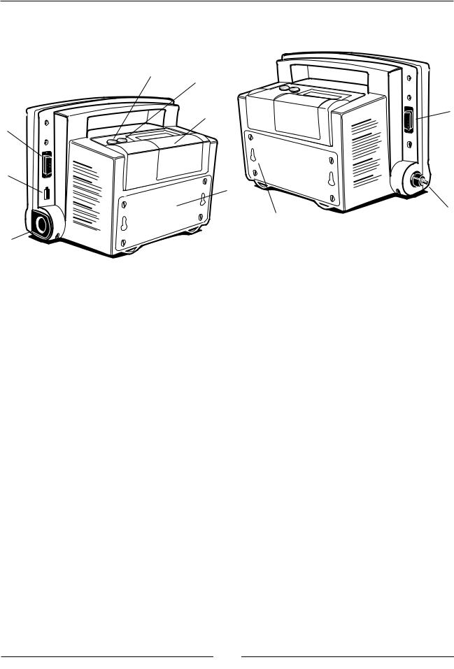
B. SIDE & REAR PANEL CONNECTIONS
8
9

 4 7
4 7 

1
 5
5
2
11
 6 10
6 10
3
1.SpO2 Sensor Connection
Nine pin connector for the SpO2 sensor.
2.Temperature Probe Connector
Connector for either oral/axillary (blue) or rectal (red) probe.
3.Temperature Probe Holder
Active temperature probe is inserted here when not in use. Removing and replacing the probe turns the temperature on and off, respectively.
4.RS232 Data Interface Connector
Port for the connection of a cable to an external computer, network, or nurse call system.
5.Transformer Power Connector
AC power transformer connector.
6.Pressure Hose Connector
Connector for black, coiled pressure hose.
7.Printer
Compartment and paper feed area for integrated thermal printer.
8.Print Button
Pressing this button initiates a print operation.
9.Printer Feed Button
Pressing this button advances the paper in the printer.
21
WELCH ALLYN VITAL SIGNS MONITOR |
OPERATOR MANUAL |
|
|
10.Mounting Keyholes
Mounting accessories are attached via these keyholes.
11.Battery Compartment
Contains the internal battery. Removal of 4 screws allows changing battery without affecting other internal parts.
III. 3. A. SET-UP PROCEDURE:
BLOOD PRESSURE HOSE & CUFF CONNECTIONS
Identify and have available each of the following items: -The Welch Allyn Vital Signs Monitor
-Cuff and bladder assembly -Black coiled pressure hose
Using the illustrations below for reference, perform the following set-up procedures:
1.Inspect the black coiled pressure hose and note that one end has a connector fitting and the other end does not. Attach the end without the connector to the pressure hose connector on the monitor by fitting the pressure hose on to the connector as shown. Be sure that the pressure hose is completely inserted over the connector and into the recess, and that the fit is snug.
Attaching pressure hose to connector on monitor
22

WELCH ALLYN VITAL SIGNS MONITOR |
OPERATOR MANUAL |
|
|
2.Join the other end of the black coiled pressure hose to the pneumatic tubing which is attached to the cuff. Twist the black connectors together until finger-tight. DO NOT OVER TIGHTEN.
23
WELCH ALLYN VITAL SIGNS MONITOR |
OPERATOR MANUAL |
|
|
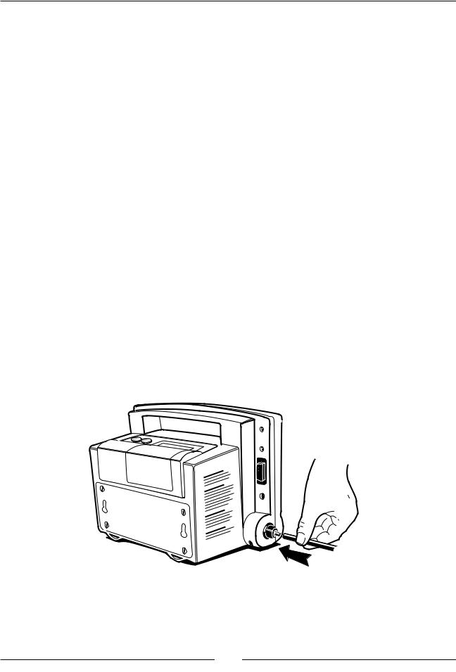
III. 3. B. SET-UP PROCEDURE:
TEMPERATURE PROBE CONNECTION
The Welch Allyn Vital Signs Monitor is available with two probes; one for oral/axillary temperatures (blue), and one for rectal temperatures (red). The rectal probe is an accessory item and must be ordered separately.
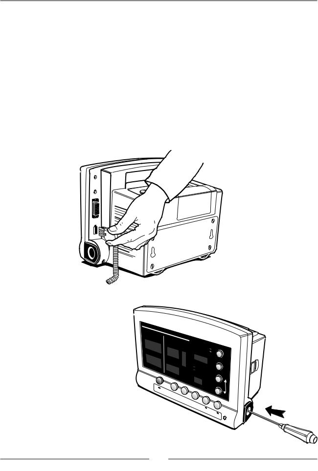
To install the temperature probe, press down on the tab on top of the connector and insert the connector into the temperature probe connector port on the side of the Monitor until the connector clicks into place. The temperature connector port on the Monitor is clearly labeled "TEMP." The probe connector can only be inserted one way, with the tab on top. The temperature probe should be inserted into the probe holder on the side of the Monitor.
Inserting the probe connector into the Monitor port
Should removal of the temperature probe be necessary, press down on the connector tab and slide the connector out.
SYSTOLIC
SpO2 |
|
(mmHg) |
|
PULSE |
(BPM) |
%
TEMPERATURE |
Pulse |
|
olume |
||
|
Tone |
|
|
V |
|
Charging |
Select |
|
Alarm |
||
Low |
||
Battery |
|
|
CYCLE |
|
|
|
Set |
|
Review |
|
|
Auto |
|
|
|
Silence |
Placing the probe into the probe holder
24
Loading...