

Page 1

Publication PB 0188
Issue 2
Watson-Marlow high flow, high pressure pump
Installation and operating instructions
Pumphead/s: 919 Issue 1
925 Issue 1
940 Issue 1
945 Issue 1
900 series
Page 2
Contents
Declarations .................................................... Page 2
Safety .................................................... Page 3
Information for returning pumps .................................................... Page 3
Two year warranty .................................................... Page 3
Recommended operating procedures ............................................. Page 4
Part 1: Installation
Siting .................................................... Page 5
Pump connections .................................................... Page 5
Electrical connection .................................................... Page 6
Powered tube removal .................................................... Page 7
Powered tube fitting .................................................... Page 8
Manual tube removal .................................................... Page 9
Manual tube fitting .................................................. Page 10
Shoe adjustment .................................................. Page 13
Part 2: Operation
Flow rates .................................................. Page 14
Part 3: Appendices
Spares .................................................. Page 16
Materials of construction .................................................. Page 18
Specification .................................................. Page 18
Outline drawing .................................................. Page 19
Declaration of
conformity
Declaration of
incorporation
Decontamination certificate .................................................. Page 20
Declarations
When a 900 series drive unit, fitted with the 900 series pumphead is used as
a stand alone pump it complies with:
Machinery Directive 89/392/EEC EN60204-1
Low Voltage Directive 73/23/EEC EN61010-1
EMC Directive 89/336/EEC EN50081-1/50082-1
Responsible person: A S Balding, Managing Director, Watson-Marlow Limited,
Falmouth, Cornwall TR11 4RU, England.
Telephone 01326 370370 Fax 01326 376009
When the 900 series pumphead is to be installed into machines or assembled
with other machines for installations, it must not be put into service until the
relevant machinery has been declared in conformity with the provisions of the
machinery directive 89/392/EEC and EN60204-1.
Responsible person: A S Balding, Managing Director, Watson-Marlow Limited,
Falmouth, Cornwall TR11 4RU, England.
Telephone 01326 370370 Fax 01326 376009
Page 2
Page 3

Safety
In the interests of safety, this pump and the tubing selected should only be
used by competent, suitably trained personnel after they have read and
understood this manual, and considered any hazard involved.
Any person who is involved in the installation or maintenance of this
equipment should be fully competent to carry out the work. In the UK this
person should also be familiar with the Health and Safety at Work Act 1974.
Do not remove or open pumphead door whilst operating pump.
Do not place fingers inside pumphead.
Ensure the drive is inoperative before opening the pumphead door.
There are dangerous voltages (at mains potential) inside the motor. If access
is required, isolate the motor from the mains before removing the terminal box
cover.
Information for returning pumps
Any equipment which has been contaminated with, or exposed to, body fluids,
toxic chemicals or any other substance hazardous to health must be
decontaminated before it is returned to Watson-Marlow or its distributor.
A certificate (a suitable blank form is included at the rear of these operating
instructions), or signed statement, must be attached to the outside of the
shipping carton.
This certificate is required even if the pump is unused. If the pump has been
used, the fluids that have been in contact with the pump and the cleaning
procedure must be specified along with a statement that the equipment has
been decontaminated.
Two year warranty
Watson-Marlow Limited warrants, subject to the conditions below, through
either Watson-Marlow Limited, its subsidiaries, or its authorised distributors, to
repair or replace free of charge, including labour, any part of this product
which fails within two years of delivery of the product to the end user. Such
failure must have occurred because of defect in material or workmanship and
not as a result of operation of the product other than in accordance with the
instructions given in this manual.
Conditions of and specific exceptions to the above warranty are:
•
Consumable items such as tubing and glands are excluded.
•
Products must be returned by pre-arrangement carriage paid to Watson-
Marlow Limited, its subsidiaries, or its authorised distributor.
•
All repairs or modifications must have been made by Watson-Marlow
Limited, its subsidiaries, or its authorised distributors or with the express
permission of Watson-Marlow Limited, its subsidiaries, or its authorised
distributors.
•
Products which have been abused, misused, or subjected to malicious or
accidental damage or electrical surge are excluded.
Warranties purporting to be on behalf of Watson-Marlow Limited made by any
person, including representatives of Watson-Marlow Limited, its subsidiaries,
or its distributors, which do not accord with the terms of this warranty shall not
be binding upon Watson-Marlow Limited unless expressly approved in writing
by a Director or Manager of Watson-Marlow Limited.
Page 3
Page 4

Recommended operating procedures
DO
keep delivery and suction lines as short as possible.
DO use the minimum number of bends in rigid pipe runs. If there must be a
bend, use a swept bend and not a tight elbow.
DO
use suction and delivery pipelines with a bore equal to or larger than the
bore of the tube fitted in the pumphead. When pumping
losses caused by increased friction can be overcome by using pipe runs with
a cross sectional area several times greater than the pumping element.
DO
run at a slow speed when pumping viscous fluids.
DO
keep the track and sliding shoe clean.
DO ensure that the correct type and volume of coolant/lubricant is used.
viscous
fluids, the
DO NOT
peristaltic pumps are self priming and will hold their prime up to several
metres, so there may be no need for non-return or foot valves, nor for the
loading valves required on many other kinds of pumps.
Any valves fitted must cause no restriction. If electrically actuated valves are
fitted, they should be interlocked so that the pump will only run when the
valves are open. Fit an automatic by-pass if manual valves are installed.
Explosion proof motors should not be used in an environment where an
explosive gas-air mixture is continuously present or present for long periods.
DO NOT
proof motor.
The temperature of any part or surface of an explosion proof motor must
always remain below the ignition temperature of the gas-air mixture it is
operating in.
The connector elbow located at the top of the pump head, enables the pump
head to be drained of lubricant or any other substance in the case of tube
failure.
If the motor/gearbox used with this 900 series pumphead is not
supplied directly by Watson-Marlow, it is important to refer to the
maintenance manual supplied with the specific motor/gearbox.
fit valves in the suction or delivery line without considering that
connect door switches or any other switch gear with an explosion
Page 4
Page 5
Part 1: Installation
Siting
If the pump is to be lifted ensure that all standard rigging practices are
adhered to. This procedure should only be carried out by qualified
personnel only who are familiar with the Health and Safety at Work Act
1974.
The pump should be situated on a flat horizontal surface where there is free
air to circulate around it. Where the tubing is entering and leaving the
pumphead there should be least 1m of tube without a bend, a removable drop
out section to aid tube replacement, and if practical, this should be of a larger
diameter than the pump tubing.
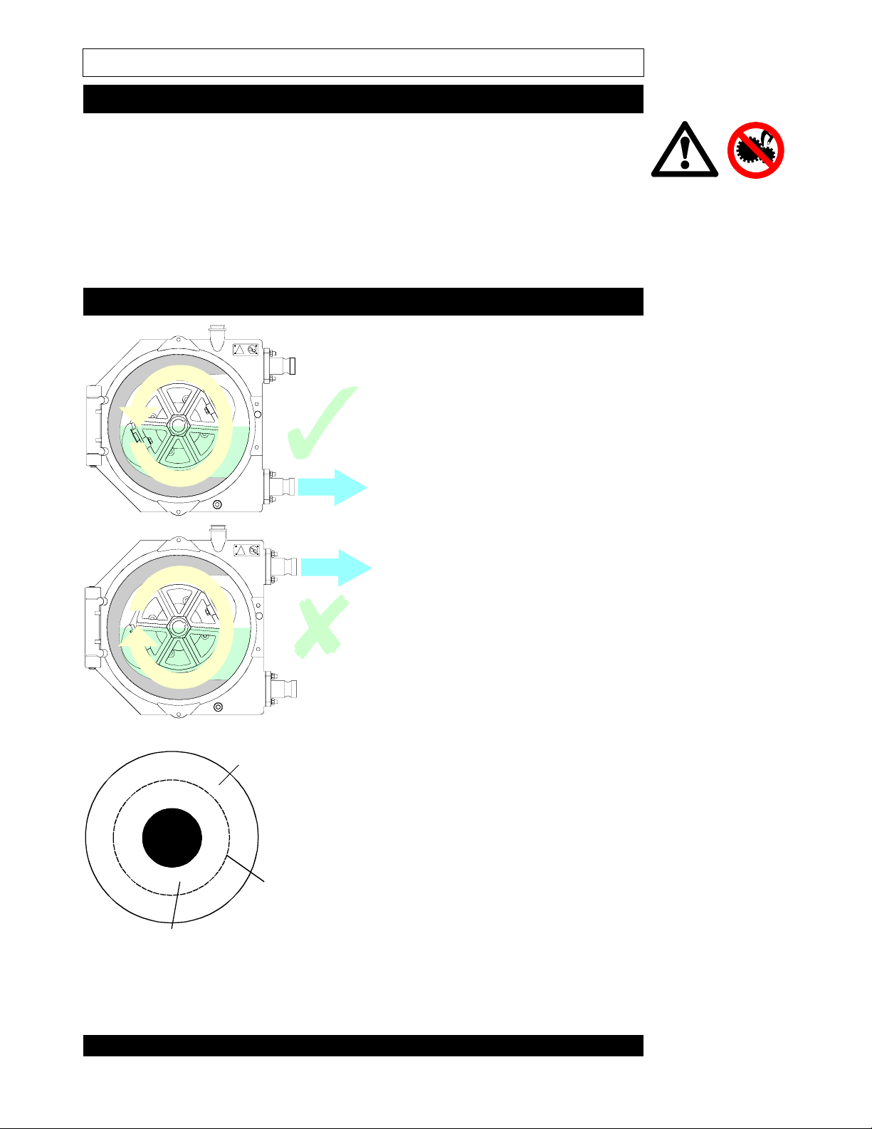
Pump connections
It is recommended that for
maximum tube life, the pump
should always be set up with the
delivery end of the tubing
connected to the lower casing
port of the pumphead and
immersed in cooling lubricant.
This may require the pump head
to be re-fitted to the correct
orientation for operation.
Natural rubber
Nylon
Reinforcing
Natural rubber
Food grade natural rubber
Food grade nitrile rubber
Neoprene rubber
EPDM
Page 5
If the main pipe run to the pump
is rigid pipe work, there should
be a drop out section or flexible
pipe work to allow the pump
tubing to be inserted and
withdrawn.
For working pressures over 7 bar,
always fit an outlet pulsation
damper. Watson-Marlow, or its
representative, can supply
pulsation dampers and will assist
with determining the type
required for your application.
900 Series tubing is available in
the combinations seen left for a
range of process requirements.
Page 6
Electrical connection
In order to effectively protect the motor from overloads, appropriate motor
protection devices must be used. Motors fitted to the Watson-Marlow series of
pumps are manufactured with a motor temperature cut-out, but a current
overload relay should also be fitted to a contact breaker.
The motor should be connected by a qualified engineer who is
conversant with the appropriate regulations and they should ensure that
the voltage and frequency of the electrical supply corresponds with the
data on the motor plate.
Connect the motor in accordance with the wiring diagram which will be found
in the motor terminal box.
When a motor thermal protection switch is fitted in the motor, the leads will be
found in the motor terminal box. They should be connected to stop the pump if
the switch operates. The switch will open circuit at an over temperature
condition.
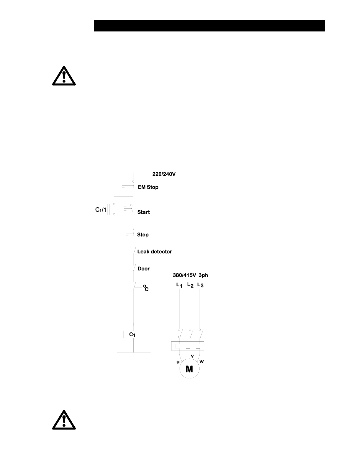
The diagram below shows the connection of the drive motor showing possible
ancillary switches and protections. It depends on the installation whether a
reversing switch and interlock with other equipment is included.
Care must be taken to ensure that
the motor terminal links are in the
correct position and that all
connections including the earth
connection are positioned
correctly and securely.
Ingress protection standard will be
compromised if the connection
box cover is not properly replaced
or if the cable gland is not
correctly fitted. Exd motors must
be connected with approved fitting
and practice.
All pumps, excluding those
intended for use in hazardous
atmospheres, may be fitted with a
door indicator switch. This switch
is rated 240V 0.5A AC Max. Power
load 50W Max. This switch is NOT
intended as a primary safety
device. Under normal operation the
pump door is kept closed and this
meets all statutory requirements
as a tool lockable fixed guard.
The switch may be used directly to
indicate that the door is open
during maintenance, or it may be
wired, following accepted fail safe
practices, into a customers start
up/shut down control system to
provide a back up to the Fixed Guard, whilst maintenance is being
carried out. However, all normal maintenance safety practices should
also be observed.
There are dangerous voltages (at mains potential) inside the motor. If
access is required, isolate the pump from the mains before removing the
cover.
Page 6
Page 7

Powered tube removal
Place a container under the
pumphead, then remove the
lubricant drainage plug and the
lubricant filler plug. Allow the
lubricant to drain from the
pumphead.
Loosen and remove the four
securing nuts on the lower casing
port connector using a 13mm
spanner.
If the pump is a variable speed
unit, run at a slow speed. Run the
pump anticlockwise until the
support ring, compression gland
and the compression ring are
outside of the pump.
Stop the pump and with two
levers, lever the connector out of
the tube, then slide off the support
and compression rings and the
compression gland. Remove the
four securing nuts on the upper
casing port connector using a
13mm spanner.
Reverse the direction of rotation of
the rotor to allow the tube to be
driven out of the pumphead.
Remove the four door locking
screws using the Allen key
supplied.
Page 7
Page 8

Powered tube fitting
Isolate the motor from the
mains supply before opening
the pumphead door.
Swing the pumphead door open.
Remove the tube from the
pumphead.
Check that there is no debris
inside the casing and that it is
clean. Check that the front casing
lubricant seal is not damaged,
then secure the door with the four
door locking screws and the Allen
key supplied ensuring the seal is
seated correctly.
Isolate the motor from the
mains supply before opening
the pumphead door.
Close and lock the pumphead
door with the four door locking
screws and Allen key supplied.
Take a new piece of tubing and
smear Silicone grease or tube
lubricating oil on the outside of the
tube. Connect motor to the mains
supply. Start the pump and with
care, feed the tube into the
pumphead following the
anticlockwise rotation of the rotor.
Continue feeding until the other
end of the tube is level with the
pump face. Stop the motor.
Slide the support ring (the shortest
ring), compression gland and the
compression ring (which has a
step to allow ease of location into
the tube port) onto the tube. Push
the connector into the pipe.
Repeat for the other end of the
tube.
➀
Connector ➁ Compression ring
➂ Support ring ➃ Tube
➄
Page 8
Compression gland
Page 9

Locate the upper port connector
with the securing nuts and the
Allen key supplied.
Rotate the rotor anticlockwise and
drive the other end of the tube out
of the lower casing port. Locate
the support ring, compression
gland and compression ring.
Locate the lower port connector
using the securing nuts and Allen
key supplied.
Replace the lubricant drainage
plug then fill the pumphead with
lubricant to the specified volume.
The window in the pumphead door
is a motion window and provides a
visual indication of the rotation of
the rotor within the pumphead.
This window should not be used
as lubricant level indicator.
Locate and secure the lubricant
filler plug.
Manual tube removal
Isolate the motor from the
mains supply before opening
the pumphead door.
Place a container under the
pumphead, then remove the
lubricant drainage plug and the
lubricant filler plug. Allow the
lubricant to drain from the
pumphead.
Remove the four door locking
screws with the Allen key
supplied. Swing the pumphead
door open.
Page 9
Page 10

Loosen the upper casing port
connector securing nuts using a
13mm spanner. Locate a spanner
on the cast hexagonal nut of the
rotor. Rotate the rotor clockwise
until one pump head shoe has left
contact with the tube completely
and the tubing has been forced
out of the upper casing port.
Lever the connector out of the
tube. Slide off the compression
ring and sealing gland.
Pull the end of the tube out of the
upper casing port and remove the
support ring. Whilst still holding
the tube, rotate the rotor
anticlockwise to enable the tube to
be withdrawn from the pumphead.
When the second shoe is clear of
the tube, remove the lower casing
port connector, compression ring
and sealing gland. Remove the
tube completely from the
pumphead along with the lower
support ring.
Manual tube fitting
Isolate the motor from the
mains supply before opening
the pumphead door.
Clean the inside and faces of both
casing ports, the compression and
support rings and sealing gland.
Clean the door sealing face
ensuring that the lubricant seal is
intact.
Page 10
Page 11

Take a new piece of tubing and
smear Silicone grease or tube
lubricating oil on the outside of the
tube. Insert the tube into the lower
casing port until it makes contact
with the rotor shoe.
Rotate the rotor whilst inserting the
tube to draw the remainder of the
tube into the pumphead. Continue
until approximately 100mm of tube
remains protruding through the
lower casing port.
Slide a support ring (the shortest
ring), a compression gland, and a
compression ring onto the tube.
Push the connector into the tube.
(See next illustration for detail).
➀
Connector ➁ Compression ring
➂
Support ring ➃ Tube
➄
Compression gland
Page 11
Page 12

Continue to rotate the rotor until the
lower tube connector is flush with
the port outer face. Tighten the
connector securing nuts to avoid
pulling the tube back through the
lower port.
Repeat connector fitting procedure
for the other end of the tube in the
upper casing port. Rotate the rotor
to ensure that the tube is seated in
the pumphead correctly.
Swing the pumphead door closed
and lock shut using the door
locking screws and the Allen key
supplied. Locate and secure the
lubricant drainage plug.
Replace the lubricant drainage plug
then fill the pumphead with lubricant
to the specified volume.
The window in the pumphead door
is a motion window and provides a
visual indication of the rotation of
the rotor within the pumphead. This
window should not be used as
lubricant level indicator.
Locate and secure the lubricant filler
plug.
Page 12
Page 13

Shoe adjustment
Normally when a pump is set up for an application there will be no need to readjust the shim setting.
The occlusion of the tube is
adjusted by varying the number of
shims that are between the shoe
and the rotor.
To add or remove shims loosen
the hexagon screw (13mm A/F)
several turns.
Check that the number of shims fitted under the sliding shoe is suitable for the
operating conditions of the pump.
25mm and 19mm
0-25 rpm
25-50 rpm
50-75 rpm
75-100 rpm 3310
40mm and 45mm 10-15 bar 5-10 bar 2-5 bar 0-2 bar
0-25 rpm 4321
25-50 rpm 4321
50-75 rpm
75-100 rpm
Increasing the number of shims under the sliding shoes will increase
tube occlusion for higher pressure operation.
This will reduce the overall tube life when compared to using fewer
shims for lower pressure operation. For temperatures above 60C - use
one shim less.
10-15 bar 5-10 bar 2-5 bar 0-2 bar
5431
4321
4321
3211
3211
Page 13
Page 14

Part 2: Operation
Flow rates
The following motor power/ tube life graphs apply to fixed speed units
only. For variable speed units the motors should be de-rated by 20%.
Page 14
Page 15

Page 15
Page 16

919/925
Part 3: Appendices
Spares
Spares
SW 0156 Door indicator switch 1
HF 1302C Door 1 11
HF 1005S Window 1 10
HF 1009S Shim 8 6
HF 1003C 919 rotor 1 7
* HF 1303C 925 rotor 1 7
FN 2806 Blanking plug 1 8
HF 1004C Shoe 2 9
HF 1305C Frame support B/RA 1 15
* HF 1304C Frame support FB/R 1 15
TT 0001 6mm A/F Allen key 1
099.0002.000 Lubricant 2 litres
OS0030 Seal 1 5
CN 0146 Coupling half 2 2
CN 0147 Coupling spider 2 1
HFA1305A Bareshaft adaptor 1 13
HF 1310T Bareshaft 1 14
BB 0045 Front bareshaft bearing 1 4
HF 1015T 919 8mm ring connector 1 12
HF 1012T 919 16mm ring connector 1 12
HF 1017M 919 compression gland 1 12
HF 1315T 925 8mm ring connector 1 12
HF 1312T 925 16mm ring connector 1 12
HF 1317M 925 compression gland 1 12
BB 0039 Rear bareshaft bearing 1 3
Description
Quantity Item
Page 16
Page 17

940/945
Spares
Description
Quantity Item
SW 0156 Door indicator switch 1
HF 1102S Door 1 6
HF 1005S Window 1 11
HF 1109S Shim 8 9
HF 1103C Rotor 1 10
FN 2806 Blanking plug 1 8
HF 1104T Shoe 2 7
HF 1123C Frame support B/RA 1 15
* HF 1105C Frame support FB/R 1 15
TT 0007 8mm A/F Allen key 1
OS 0030 Seal 1 5
099.0005.000 Lubricant 5 litres
CN 0144 Coupling half 2 1
HF 1120T Bareshaft 14
CN 0145 Coupling spider 1 2
HFA1105A Bareshaft adaptor 1 13
BB0046 Front bareshaft bearing 1 4
BB0042 Rear bareshaft bearing 1 3
HF 1115T
HF 1116T
HF 1117M
HF 1161T
HF 1162T
HF 1163M
940 8mm ring connector
940 16mm ring connector
940 compression gland
945 8mm ring connector
945 16mm ring connector
945 compression gland
112
112
112
112
112
112
Page 17
Page 18

Materials of construction
Description Material Comment
Pumphead Body
Pumphead Door
Pumphead Rotor Grey iron Epoxy polyester powder coat
Rotor Shoes Aluminium
Frame Mild steel Epoxy polyester powder coat
Flanges Mild steel, stainless
Studs for
connectors
Door fixings High tensile steel
Motor fixings High tensile steel
Frame fixings Stainless steel
Tube sealing
glands
Tube lubricant Glycerine Green in colour
Cast iron A high quality and strength cast
iron, with an epoxy polyester
powder coat finish
See separate section on flanges
steel, aluminium or
polypropylene
Stainless steel
Neoprene See section on tube connection
Specification
Control range See pump specification label
Voltage/frequency See motor specification label
Power consumption See motor specification label
Operating temperature range 5C to 40C
Storage temperature range -40C to 70C
Noise <70dBA at 1m
Standards IEC 335-1, EN60529 (IP55)
Machinery Directive:
89/392/EEC EN60204-1
Low Voltage Directive:
73/23/EEC EN61010-1
EMC Directive: 89/336/EEC
EN50081-1/50082-1
Page 18
Page 19

Outline drawing
410 (430)
620 (730)
NORMAL DIMENSIONS REPRESENT 919
DIMENSIONS IN BRACKETS REPRESENT 925
919/25
)
0
3
4
(
0
8
3
940/45
650
0
1
6
840
Page 19
Page 20

Decontamination certificate
g
g
g
Watson-Marlow Limited Health and Safety Declaration
1.0
This procedure is a legal requirement in the UK
and
be used when returning pumps and to Watson-Marlow (or its distributor) to
must
equipment for service at Watson-Marlow (or its that we have the information
3.0
Either fax this form or send by first class post
receipt of the
before
ensure
distributor). equipment.
2.0
Pumps returned for service must be cleaned.
You are responsible for their decontamination. outside
A further copy must be attached to the
of the shipping case.
Failure to complete the form or comply with the procedure will cause delays in servicing the equipment.
4.0
Company .......................................................................................................................................................
Address .......................................................................................................................................................
......................................................... Post Code........................................................
Telephone ......................................................... Fax number.....................................................
5.0
Please complete
the following sections
all
5.4
If substances are not hazardous nor toxic,
please complete section 5.4.1.
If substances are hazardous or toxic,
5.1
Pump Type....................................................... please complete section 5.4.2.
5.2
Serial number...................................................
5.4.1
I hereby confirm that the equipment specified
has not pumped nor come into contact with
any toxic or hazardous substances.
5.3
Details of substances pumped
Si
ned.............................................................
5.3.1
Chemical names: Name...............................................................
(a) ................................................................... Position...........................................................
(b) ................................................................... Date.................................................................
(c) ...................................................................
(d) ...................................................................
5.4.2
I hereby confirm that the only toxic or
hazardous substance(s) that the equipment
5.3.2
Precautions to be taken in handling these specified has pumped or come into contact
substances: with are those named, and that the
(a) ................................................................... information given is correct and the carrier
(b) ................................................................... has been informed if the consignment is of
(c) ................................................................... a hazardous nature.
(d) ...................................................................
Si
ned.............................................................
5.3.3
Action to be taken in the event of human Name..............................................................
contact: Position...........................................................
(a) ................................................................... Date................................................................
(b) ...................................................................
(c) ...................................................................
5.5
Carrier to be used
(d) ................................................................... ........................................................................
Delivery date
5.3.4
Cleaning fluid to be used if residue of ........................................................................
chemicals is found during servicing:
(a) ...................................................................
5.6
Fault description or any other information
(b) ................................................................... ........................................................................
(c) ................................................................... ........................................................................
(d) ................................................................... ........................................................................
........................................................................
........................................................................
IMPORTANT
Before returning any product for service, this form
be completed and sent to
must
Watson-Marlow, or its subsidiary, or its official distributor undertaking the service
Watson-Marlow Limited, Falmouth, Cornwall TR11 4RU, En
land. Tel 01326 370370, Fax 01326 376009
Page 20
 Loading...