

Page 1

Watson-Marlow 825 and 840 User Manual 1
WATSON-MARLOW BREDEL MANUALS
Watson-Marlow
825 / 840 pumps
m-825-840-gb-03
1 Declaration of conformity 2
2 Declaration of incorporation 2
3 Two-year warranty 2
4 Information for returning pumps 3
5 Safety 3
6 Dimensions 4
7 Recommended operating
procedures 5
8 Installation 5
9 Tube fitting 6
10 Tube removal 7
11 Roller adjustment 8
12 CIP 8
13 SIP 9
14 High pressure operation 9
15 Tubing 9
16 Materials of construction 9
17 Specification 10
18 Spares 10
19 Flow rates 11
20 Occlusion setting 12
21 Product codes 12
22 Warning not to use pumps in
patient-connected applications 12
23 Publication history 12
24 Decontamination certificate 13
Contents
Page 2

Watson-Marlow 825 and 840 User Manual 2
1 Declaration of conformity
This declaration was issued for Watson-Marlow 825 and 840 pumps on
August 1, 2006. When this pump unit is used as a stand-alone pump it
complies with: Machinery Directive 2006/42/EC, Low Voltage Directive
2004/108/EC. See 8 Pump specifications.
2 Declaration of incorporation
When this pump unit is to be installed into a machine or is to be assembled with
other machines for installations, it must not be put into service until the relevant
machinery has been declared in conformity with the Machinery Directive 2006/42/EC
BS EN 60204-1.
Responsible person: David Cole, Managing Director, Watson-Marlow Limited,
Falmouth, Cornwall TR11 4RU, England. Telephone +44 (0) 1326 370370 Fax +44
(0) 1326 376009.
The information in this user guide is believed to be correct at the time of publication. However, Watson-Marlow Limited accepts no liability for errors or omissions.
Watson-Marlow Bredel has a policy of continuous product improvement, and
reserves the right to alter specifications without notice. This manual is intended for
use only with the pump it was issued with. Earlier or later models may differ. The
most up-to-date manuals appear on the Watson-Marlow website: http://www.watson-marlow.com
3 Two-year warranty
Watson-Marlow Limited warrants, subject to the conditions below, through either
Watson-Marlow Limited, its subsidiaries, or its authorised distributors, to repair or
replace free of charge, any part of this product which fails within two years of delivery of the product to the end user. Such failure must have occurred because of
defect in material or workmanship and not as a result of operation of the product
other than in accordance with the instructions given in this manual.
Conditions of and specific exceptions to the above warranty are:
Consumable items such as rollers and tubing are excluded.
Products must be returned by pre-arrangement, carriage paid, to Watson-
Marlow Limited, its subsidiaries, or its authorised distributor.
All repairs or modifications must have been made by Watson-Marlow Limited,
its subsidiaries or its authorised distributors or with the express permission of
Watson-Marlow Limited, its subsidiaries, or its authorised distributors.
Products which have been abused, misused, or subjected to malicious or acci-
dental damage or electrical surge are excluded.
Warranties purporting to be on behalf of Watson-Marlow Limited made by any
person, including representatives of Watson-Marlow Limited, its subsidiaries, or its
distributors, which do not accord with the terms of this warranty shall not be
binding upon Watson-Marlow Limited unless expressly approved in writing by a
Director or Manager of Watson-Marlow Limited.
Page 3

Watson-Marlow 825 and 840 User Manual 3
4 Information for returning pumps
Equipment which has been contaminated with, or exposed to, body fluids, toxoc
chemicals or any other substance hazardous to health must be decontaminated
before it is returned to Watson-Marlow or its distributors.
A certificate included at the rear of these operating instructions, or a signed statement, must be attached to the outside of the shipping carton.
This certificate is required even if the pump is unused. If the pump has been used,
the fluids that have been in contact with the pump and the cleaning procedure must
be specified, along with a statement that the equipment has been decontaminated.
5 Safety
In the interests of safety, these pumpheads and the products selected should only
be used by competent, suitably trained personnel after they have read and understood this manual, and considered any hazard involved. In the UK this person should
be familiar with the Health and Safety at Work Act 1974.
Any person who is involved in the installation or maintenance of the equipment
should be fully competent to carry out the work.
There are dangerous voltages (at mains potential)
inside the terminal box. If access is required, isolate
the pump from the mains before removing the terminal
box cover. Do not olace any part of the body inside the pumphead while the pump is running.
Page 4
Watson-Marlow 825 and 840 User Manual 4
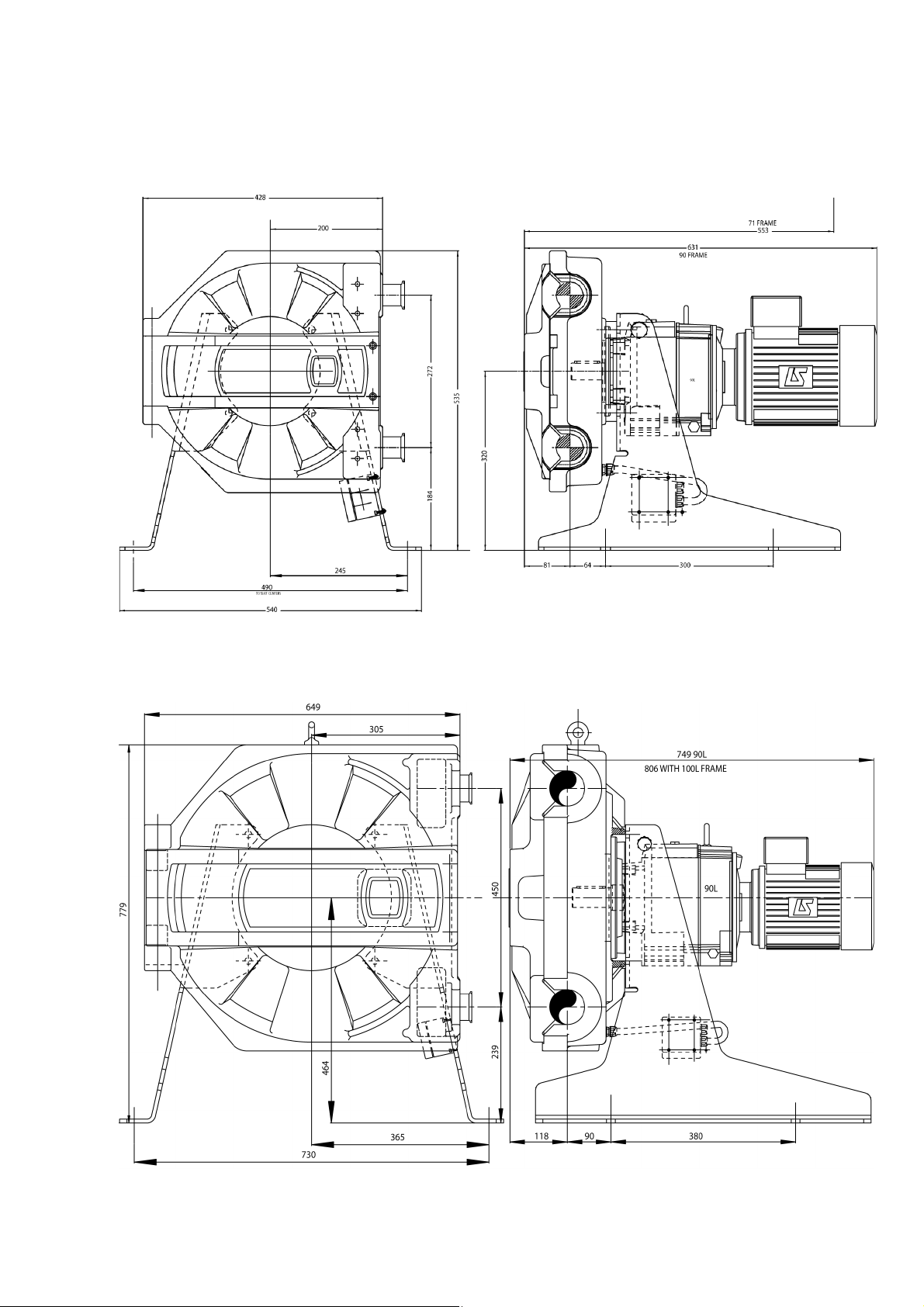
6 Dimensions in mm
825
840
Page 5

Watson-Marlow 825 and 840 User Manual 5
7 Recommended operating
procedures
Do keep delivery and suction tubes as short and direct as possible using a minimum
of swept bends
Do use suction and delivery pipes equal to or larger than the bore of the tube in the
pumphead. When pumping viscous fluids, the losses caused by increased friction can
be overcome by using pipe runs with a cross sectional area several times greater
than the pumping element.
Do keep the pumphead track and all moving parts clean and free from contamination and debris.
The self-priming nature of peristaltic pumps means valves are not required. Any
valves fitted must cause no restriction to flow in the pumping circuit.
If the rotor is run in an anticlockwise direction with both rocker mechanisms
unlocked no tube occlusion will occur. In this case the rocker mechanisms will snap
back from their disengaged position when losing contact with the tubing. No damage to the pumphead action will be caused by this, however it is not advisable to
allow this action to continue for a prolonged procedure.
8 Installation
Site the pump on a flat horizontal surface allowing a free flow of air around the
pump. Ensure there is 1m of straight tubing before the pumphead inlet and discharge ports.
When requested, motors fitted to Watson-Marlow pumps incorporate a thermal protection switch which may be used to provide indication of an over-temperature condition. Aside from this, a current overload relay should also be fitted to a contact
breaker. Connect the motor in accordance with the wiring diagram which will be
found in the motor terrminal box.
When a thermal protection switch is fitted in the motor, the leads will be found in
the motor terminal box. They should be connected to stop the pump if the switch
operates. The switch will open circuit at an over temperature condition. See picture
for the simplest connection.
All pumps may be fitted with a door indicator switch. This switch is rated 240V 0.5A
AC maximum power load 50W. This switch is not intended as a primary safety
device. Under normal operation the pumphead door is kept closed and this meets all
statutory requirements as a tool lockable fixed guard.
Do not connect the door switch a back up or any other switch gear with the terminal box of an explosion proof motor unless the switch has a suitable Exd rating for
the zone area in which it is to be mounted.
Page 6

Watson-Marlow 825 and 840 User Manual 6
9 Tube fitting
Insert tube couplings
Unlock one rocker assembly (top left)
Position rotor in pumphead (top right)
Locate one tube end in lower clamp and secure. Feed the tubing into pumphead
clockwise while folding in the unlocked rocker assembly.
Locate the other tube end into
upper clamp and secure (above
left)
Close door. Turn on power supply
to motor
Rotate rotor clockwise until
unlocked rocker assembly snaps
into engaged position (above
right)
Isolate the motor from the power
supply
Open pumphead door. Lock rock-
er assembly (top left)
Tighten door locking screws
(right)
Page 7

Watson-Marlow 825 and 840 User Manual 7
10 Tube removal
Isolate the motor from the power
supply
Undo the door locking screws (above
left)
Unlock the rocker assembly not in
contact with the tube using the locking knob (above right)
Close the pumphead door. Switch on
the power. Rotate rotor anticlockwise until unlocked rocker rests
against the tube (right)
Isolate the motor from the power
supply. Open pumphead door
Undo the tube clamps (right)
Clean pumphead door and face
Remove coupling from tubing (below
right)
Page 8

Watson-Marlow 825 and 840 User Manual 8
11 Roller adjustment
Loosen the roller locking nut (1) and undo rock-
er locking nuts (2)
Undo the roller spindle locking nuts
Rotate roller for occlusion adjustment (below).
Setting 2 represents the factory default setting.
12 CIP
When using a clockwise pumping direction and unlocked rockers no adjustment is
required. If rockers are locked for bi-directional pumping unlock one rocker mechanism. Rotate rotor anticlockwise until no tube occlusion occurs. The free flow of
cleaning agents through the tubing is now possible.
Ensure that no part of the body inside the pumphead
while the pump is running.
Page 9

Watson-Marlow 825 and 840 User Manual 9
13 SIP
Observe a 1m safety area to avoid possible scalding if a tube burst occurs. Monitor
the process continuously .
If a tube burst occurs shut down the process, do not touch the pumphead until a 10
minute cooling period has been observed. Ensure a 15 minute acclimatisation period is observed before running the pump following SIP.
Maximum permissible SIP process temperature is 135 C.
14 High pressure operation
Ensure rocker mechanisms are locked to avoid premature wear.
Observe a 1m safety area to avoid contact with high pressure jets in the case of
a tube burst.
Please note that only tubing elements and not continuous lengths of tubing can be
used for higher pressure operation.
No quick connectors are to be used with element tubing during high pressure
operation.
15 Tubing
No length of tubing which has previously been used as a pumping element should
be used in the transfer section due to the fact that it may be in a weakened condition.
16 Materials of construction
Description Material Finish
Pumphead body Aluminium Epoxy polyester powder coated white finish
Pumphead door Aluminium Epoxy polyester powder coated white finish
Pumphead rotor Aluminium Epoxy polyester powder coated
Rollers Stainless steel 316
Frame Stainless steel 304
Connectors Stainless steel 316
Door fixings High tensile steel
Motor fixings High tensile steel
Frame fixings Stainless steel
Rocker locking
knob, 840
Polypropylene
Rocker locking
knob, 825
Stainless steel
Ensure that the pumphead door is closed and tool-
locked before SIP cleaning
Page 10

Watson-Marlow 825 and 840 User Manual 10
17 Specification
Control range See pump specification label
Voltage/frequency See pump specification label
Power consumption See pump specification label
Operating temperature range 5C to 40C
Storage temperature range -40C to 70C
Noise 70dB(A) at 1m
Standards IEC 335-1, EN60529 (IP55)
Machinery Directive 2006/42/EC
Low Voltage Directive 2004/108/EC
Number 825 spare 840 spare Description
1 HFA1201A HFA1401A Tube clamp
2 HFA1205A HFA1405A Rocker assembly
3 HFA1206A HFA1406A Rotor assembly
4 HF1202C HF1402C Door
5 HF1005S HF1005S Window
6
(not shown)
HF1271S
HF1272S
HF1467S
HF1468S
Frame support RH
Frame support LH
7 HF1201C HF1401C Track
8 HFA1204A HFA1404A Roller assembly
9 HFA1202A HFA1202A Terminal box
18 Spares
Page 11

Watson-Marlow 825 and 840 User Manual 11
19 Flow rates
825
840
Page 12

Watson-Marlow 825 and 840 User Manual 12
20 Occlusion setting
825 840
Occlusion
setting
Roller to track
clearance
% tube over-
occlusion
Roller to track
clearance
% tube over-
occlusion
Bottom 17.0 6% 24.0 8%
Left 16.2 10% 23.1 11%
Right 15.7 13% 22.5 14%
Top 15.0 16% 21.7 17%
21 Product codes
825 Bioprene
Maximum working
presssure
Tube bore Product code
770mm long ± 3mm 2 bar 25mm 088.T250.E0P
770mm long ± 3mm 3.5 bar 25mm 088.T250.E0G
2310mm long 2 bar 25mm 088.T250.00P
2310mm long 3.5 bar 25mm 088.T250.00G
840 Bioprene
Maximum working
presssure
Tube bore Product code
1250mm long ± 4mm 2 bar 40mm 088.T400.E0P
1250mm long ± 4mm 3.5 bar 40mm 088.T400.E0G
22 Warning not to use pumps in
patient-connected applications
Warning: These products are not designed for use in, and should not be used for
patient-connected applications.
23 Publication history
m-825-840-gb-03.qxp: Watson-Marlow 825, 840
First published 07 06. This edition published 11 14.
Page 13

Watson-Marlow 825 and 840 User Manual 13
Your name
Company
Address
Postcode/zip Country
Telephone Fax
Product type Serial number
To speed the
repair, please
describe all
known faults
The product has ...
II Been used II Not been used
If the product has been used, please complete all the following sections.
If the product has not been used, please just sign this form.
Names of
chemicals handled
with product(s)
Precautions to be
taken in handling
these chemicals
Action to be taken
in the event of
human contact
I understand that the personal data collected will be kept confidentially
in accordance with the UK Data Protection Act 1998.
RGA number
Signature Your position
Date
Please print out, sign and fax to Watson-Marlow Pumps at +44 1326 376009.
24 Decontamination certificate
In compliance with the UK Health and Safety at Work Act and the Control of
Substances Hazardous to Health Regulations, you are required to declare the substances which have been in contact with product(s) you return to Watson-Marlow or
its subsidiaries or distributors. Failure to do so will cause delays. Please ensure that
you fax us this form and receive an RGA (Returned Goods Authorisation) before you
despatch the product(s). A copy of this form must be attached to the outside of the
packaging containing the product(s). Please complete a separate decontamination
certificate for each product. You are responsible for cleaning and decontaminating
the product(s) before return.
 Loading...