

Page 1

Watson-Marlow Bredel E-Manuals
Search manual for ...
Go
WATSON-MARLOW BREDEL E-MANUALS
m-624di-gb-01
Watson-Marlow 624Di pumps
Clickable index
1. Declaration of conformity
2. Declaration of incorporation
3. Warranty
4. Information for returning pumps
5. Safety
6. Recommended operating
procedures
7. Installation
8. Rear panel recess
9. Troubleshooting
10. User interfacing
11. Dosing procedure
12. Calibration procedure
13. Manual operation
14. Auto operation
15. Setup
16. Remote control
17. Care and maintenance
18. Guard safety warnings
19. Specification
20. Drive spares
21. 620RE, 620RE4 and 620R Key
safety information
22. 620RE, 620RE4 and 620R Safeguarding
23. 620RE, 620RE4 and 620R
Pumping conditions
24. 620RE, 620RE4 and 620R Pump
installation
25. 620RE, 620RE4 and 620R
General operation
26. 620RE and 620RE4 tube element loading
27. 620RE, 620RE4 and 620R Continuous tube
loading
28. 620RE, 620RE4 and 620R Tube element or
continuous tube removal
29. 620RE, 620RE4 and 620R Maintenance
30. 620RE, 620RE4 and 620R CIP and SIP
31. 620RE, 620RE4 and 620R Pumphead spares
32. 625L Pumphead
33. 625L Installation
34. 625L Tube loading
35. 625L Care and maintenance
36. 625L Track adjustment
37. 625L Pumphead spares
38. 625L Operation
39. 625L Error Messages
40. 620RE, 620RE4 and 620R Technical data
41. Flow rates
42. Dimensions in mm
43. 620R product codes
44. 620RE and 620RE4 LoadSure product codes
45. 620R dosing guidelines
46. 625L dosing guidelines
47. 625L product codes
48. 625L (4mm) product codes
49. 625L Y-piece product codes
50. Trademarks and disclaimer
51. Patient-connected use: warning
52. Publication history
53. Decontamination certificate
Double clicking anywhere in the manual will take you back to this index.
Declaration of conformity
When this pump unit is used as a stand-alone pump it complies with: Machinery
Directive 98/37/EC EN60204-1, Low Voltage Directive 73/23/EEC EN61010-1, EMC
Directive 89/336/EEC, EN50081-1/EN50082-1.
Declaration of incorporation
When this pump unit is to be installed into a machine or is to be assembled with other
machines for installations, it must not be put into service until the relevant machinery has
been declared in conformity with the Machinery Directive 98/37/EC EN60204-1.
Responsible person: Christopher Gadsden, Managing Director, Watson-Marlow Limited,
Falmouth, Cornwall TR11 4RU, England. Telephone +44 (0) 1326 370370 Fax +44 (0)
1326 376009.
http://www.watson-marlow.it/pdfs-global/m-624Di-gb-01.htm[10/07/2012 13:59:15]
Page 2

Watson-Marlow Bredel E-Manuals
Two year warranty
Watson-Marlow Limited warrants, subject to the conditions below, through either WatsonMarlow Limited, its subsidiaries, or its authorised distributors, to repair or replace free of
charge, including labour, any part of this product which fails within two years of delivery of
the product to the end user. Such failure must have occurred because of defect in material
or workmanship and not as a result of operation of the product other than in accordance
with the instructions given in this manual.
Conditions of and specific exceptions to the above warranty are
Consumable items such as tubing and rollers are excluded.
Products must be returned by pre-arrangement carriage paid to Watson-Marlow Limited,
its subsidiaries, or its authorised distributor.
All repairs or modifications must have been made by Watson-Marlow Limited, its
subsidiaries, or its authorised distributors or with the express permission of WatsonMarlow Limited, its subsidiaries, or its authorised distributors.
Products which have been abused, misused, or subjected to malicious or accidental
damage or electrical surge are excluded.
Warranties purporting to be on behalf of Watson-Marlow Limited made by any person,
including representatives of Watson-Marlow Limited, its subsidiaries, or its distributors,
which do not accord with the terms of this warranty shall not be binding upon WatsonMarlow Limited unless expressly approved in writing by a Director or Manager of WatsonMarlow Limited.
Information for returning pumps
Equipment which has been contaminated with, or exposed to, body fluids, toxic chemicals
or any other substance hazardous to health must be decontaminated before it is returned
to Watson-Marlow or its distributor. A certificate included at the rear of these operating
instructions, or signed statement, must be attached to the outside of the shipping carton.
This certificate is required even if the pump is unused. If the pump has been used, the
fluids that have been in contact with the pump and the cleaning procedure must be
specified along with a statement that the equipment has been decontaminated.
Safety
In the interests of safety, this pump and the tubing selected should only be used by
competent, suitably trained personnel after they have read and understood this manual,
and considered any hazard involved.
Any person who is involved in the installation or maintenance of this equipment should be
fully competent to carry out the work. In the UK this person should also be familiar with
the Health and Safety at Work Act 1974.
This symbol, used on the pump and in this manual, means: Caution, risk
of electric shock.
This symbol, used on the pump and in this manual, means: Caution, refer
to accompanying documents.
This symbol, used on the pump and in this manual, means: Do not allow
fingers to contact moving parts.
There are dangerous voltages (at mains potential) inside the
pump. If access is required, isolate the pump from the mains
before removing the cover.
Recommended operating procedures
DO keep delivery and suction lines as short as possible using a minimum number of swept
bends.
DO use suction and delivery pipelines with a bore equal to or larger than the bore of the
http://www.watson-marlow.it/pdfs-global/m-624Di-gb-01.htm[10/07/2012 13:59:15]
Page 3
Watson-Marlow Bredel E-Manuals
tube fitted in the pumphead. When pumping viscous fluids, the losses caused by increased
friction can be overcome by using pipe runs with a cross sectional area several times
greater than the pumping element.
DO fit an extra length of pump tube in the system to enable tube transfer. This will extend
tube life and minimise the downtime of the pumping circuit.
DO keep the track and rollers clean.
The self-priming nature of peristaltic pumps means valves are not required. Any valves
fitted must cause no restriction to flow in the pumping circuit.
When using Marprene tubing, after the first 30 minutes of running, re-tension the tube in
the pumphead. Open the guard, hold the tubing at one port whilst pulling the tube tight
through the second port. This is to counteract the normal stretching that occurs with
Marprene which can go unnoticed and result in poor tube life.
Tube selection The chemical compatibility list published in the Watson-Marlow catalogue
is only a guide. If in doubt about the compatibility of a tube material and the duty fluid,
request a tube sample card for immersion trials.
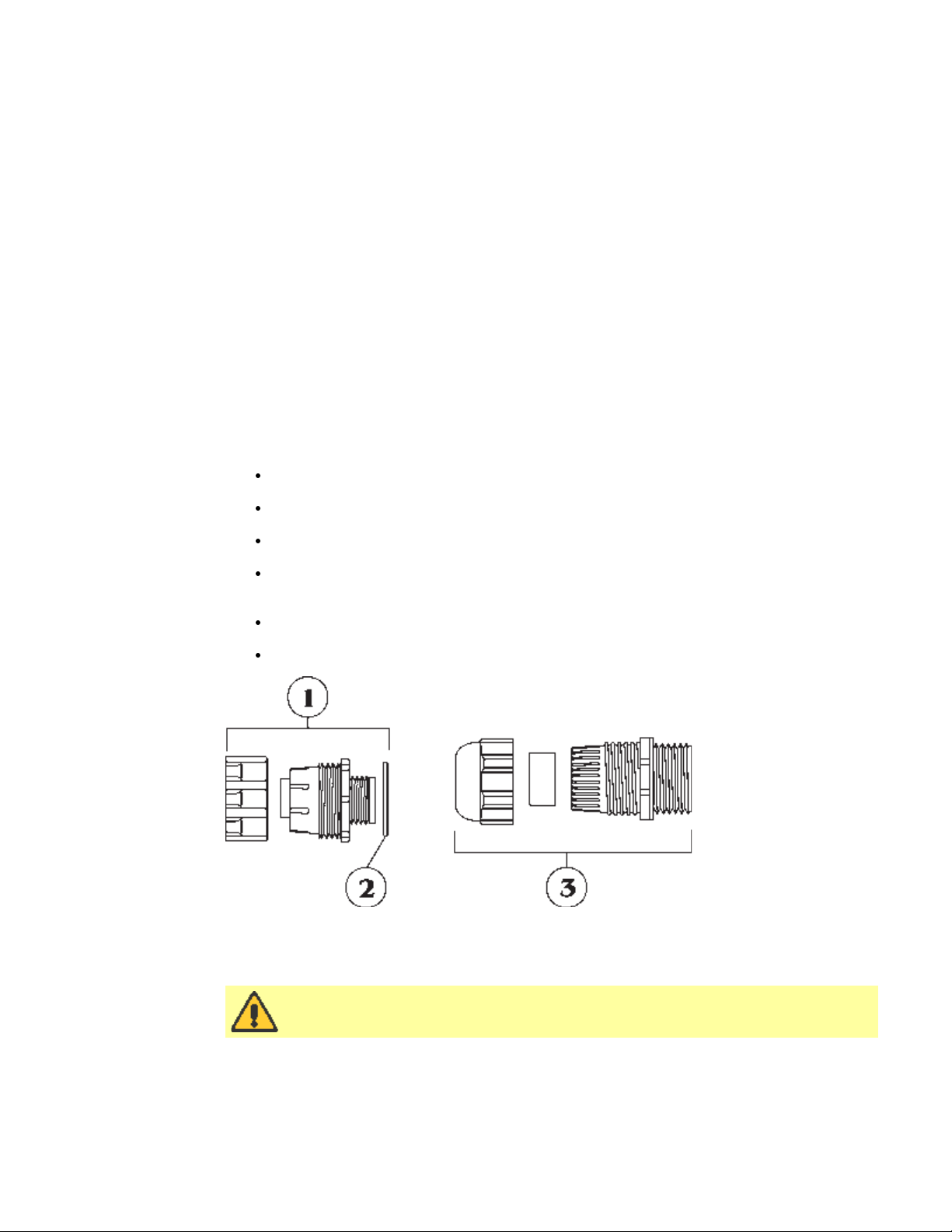
Installation
The 624Di is suitable for single-phase mains electricity supplies only.
To ensure correct lubrication of the gearbox the pump should be run only while its feet are
standing on a horizontal surface. The pump should be positioned to allow a free flow of air
around it.
Remove the small transparent plate on the rear panel to gain access to the voltage
selector and terminal block.
Set the voltage selector to either 120V for 100-120V 50/60Hz single-phase AC
supplies or 240V for 220-240V 50/60Hz single-phase AC supplies.
Route the mains supply cable through the entry point to the right of the recess, and
couple the cable to the terminal block as shown on the rear panel.
There are two alternative connectors. One accepts 20mm rigid or flexible conduit,
and the other accepts three core 0.75 square millimetre PVC sheathed mains cable
(via the screwed adapter supplied) so that a mains lead can be used.
Ensure that the mains lead is securely retained in the strain relief gland so that IP55
ingress protection is maintained.
Securely replace the transparent plate and the gasket over the recess.
1. Armoured cable strain relief gland GR 0018
2. Washer GR 0019
3. Strain relief gland SL0020
Ingress protection standard will be compromised if the transparent plate
is not replaced.
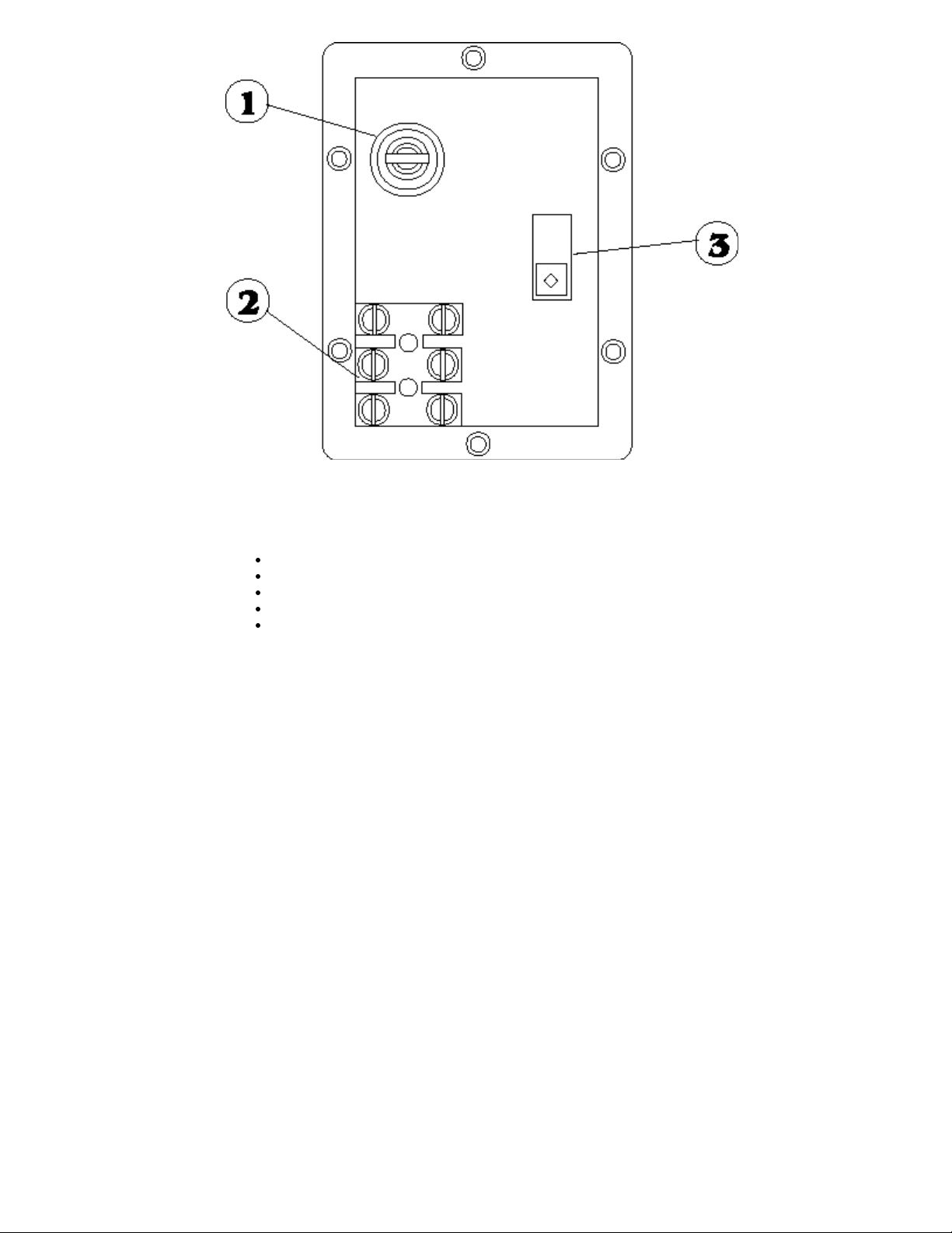
Rear panel recess
The pump rear panel recess houses the following:
1. Fuse holder
2. Terminal block
3. Voltage selection switch
http://www.watson-marlow.it/pdfs-global/m-624Di-gb-01.htm[10/07/2012 13:59:15]
Page 4
Watson-Marlow Bredel E-Manuals
to ensure the highest accuracy possible.
Troubleshooting
Should the pump fail to operate, make the following checks to determine whether or not
servicing is required.
Check that the power switch is on.
Check the mains supply is available at the pump.
Check the voltage selector switch is in the correct position.
Check the fuse in the mains socket.
Check that the pump is not stalled by incorrect fitting of tubing.
User interfacing
When powering-up the pump the user will be taken into the main menu.
Use the Step key to move between menu options. Use the Enter key to confirm settings.
Use the number keys to enter in settings. Use the Up or Down key to increase or decrease
set values in the pump software i.e. ramp settings, date, rpm etc.
Dose permits the set-up of dose programs for dispensing. A dose can be initiated by using
the Start button or external switching. The pump will allow up to 26 dosing programs to be
stored and recalled at any time. A printer can be connected to the pump for recording of
dispense runs. Batch and operator codes must be entered when using a printer.
Cal allows the pump to be calibrated for accurate dosing.
Manual allows continuous transfer/fluid metering via keypad control.
Auto enables analogue or RS232 control.
Setup displays and controls the user and factory settings for the correct operation of the
pump.
The speed/volume flow rate of the drive is governed by the pumphead and tubing selected.
Dosing procedure
The Dosing program is outlined in the technical data section of the operating instruction in
a flow chart format. Each step in the procedure is described to provide full understanding of
the procedure.
Within the technical data section are mean values for dose time guidelines and accuracy
figures recorded using Silicone tubing at zero suction and pressure. For the highest
accuracy use small-bore tubing and maximum roller passes. Always use a calibration dose
http://www.watson-marlow.it/pdfs-global/m-624Di-gb-01.htm[10/07/2012 13:59:15]
Page 5

Watson-Marlow Bredel E-Manuals
Print audit routines
If a printer is connected, the completion of a dose run will automatically call the print
routine. The first request will be to enter the operator ID.
Up to 16 characters can be entered. Digits and the decimal point are entered directly from
the keypad. Alpha characters are entered by pressing Up or Down which call A to Z and Z
to A respectively in circular rotation.
An alpha character is embedded by pressing Step. A numeric character is entered by
pressing Step, any other numeric character, the decimal point or Up or Down.
On pressing Enter, the pump will request the input of a batch number.
Again, up to 16 characters can be entered as for the operator ID. When Enter is again
pressed, the following information is printed out: date, time, dose size, specific gravity,
dose interval, number of doses, initial ml/rev, recalibration data, operator ID, batch
number and number of doses delivered.
Following the print-out a repeat dose option will be given.
Single dose command
Single doses can be dispensed on demand, with a count of the number of doses being
kept.
Set the interval time to 0 SECONDS and the number of doses to 1.
To start single dosing, press Start or use an external start dose switch. The display will
indicate the total number of completed doses up to a maximum of 99,999, after which the
counter will restart at 0: dose 100,001 would be shown as 1.
Calibration procedure
Calibration of the 624Di is based on informing the pump under Cal of the pumphead and
tubing which are to be used. Alternatively a calibration dose can be used. The calibration
dose will run for a maximum of 4 minutes, but can be stopped at any time up to 4
minutes. The longer the calibration dose, the more accurate the calibration. Entering into
the pump the physical volume or mass to complete the procedure will allow the pump to
take into account ambient conditions and also the viscosity of the fluid.
Manual operation
Switch power on.
Change the set speed by pressing the Up or Down key. The minimum speed of the
624Di is 4 rpm.
Change direction by pressing the CW/CCW key. Indication of direction of rotation is
provided via the LCD display.
Select the maximum speed: press the Up key and the Max key together. Select the
minimum speed: press the Down key and the Max key together.
Press Start to start the pump. Press Stop to stop the pump.
Auto operation
The pump will accept external control signals through the 25-pin cage clamp connector on
the back panel. Remove the cover plate, ensuring that the gasket is not damaged. Feed
the control wires through the cable glands and connect via the sprung cage clamps.
Analogue
This function enables the pump speed to be controlled via an external analogue process
signal. Pressing Enter at analogue will call a confirmation of the analogue control signal
settings. These can be reset under Setup (see section covering pump setup).
RS232
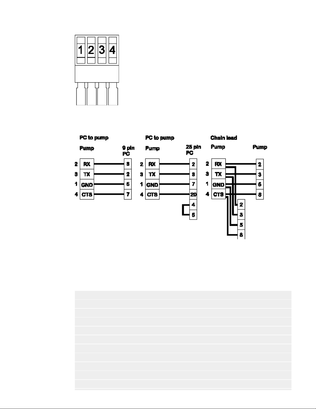
This facility gives full pump functionality under RS232 closed loop control via the 4-pin
cage clamp. Up to 16 pumps can be linked while retaining individual pump control by using
lead PR0036. A network kit is available from Watson-Marlow which includes Pumpnet 2, a
DOS-compatible control program, and leads.
http://www.watson-marlow.it/pdfs-global/m-624Di-gb-01.htm[10/07/2012 13:59:15]
Page 6
Watson-Marlow Bredel E-Manuals
Step to Network in the Main menu and press Enter. The pump will now be under RS232
control. The keypad Stop key will act as an emergency stop and disable RS232 settings if
pressed.
Above: Connections for RS232 signals: 1 = GND, 2= RX, 3 = TX, 4 = CTS
Below: RS232 cabling shown for CTR handshake. Use only twin shielded RS232
cables.
RS232 settings
Baud = 9600; Stop bits = 2; Data bits = 8; Parity = None; Handshake = CTR or
None; Auto echo = On.
The following codes will operate the 624Di under RS232 control. They must be directed to
the pump from a computer serial port (or equivalent). Always terminate each command
with a RETURN (ASCII CHR13).
nSPxxx Load speed setting xxx to pump number n
nSI Increment speed by 1rpm for pump n
nSD Decrement speed by 1rpm for pump n
nGO Start pump number n
nST Stop pump number n
nRC Change rotation direction for pump n
nRR Set clockwise direction for pump n
nRL Set counter-clockwise direction for pump n
nDOxxxxx,yyy Set dose for pump number n in tachometer pulses (note 3)
nRS Show status for pump number n (note 4)
nZY Show status if pump n STARTed 1 or STOPped 0
http://www.watson-marlow.it/pdfs-global/m-624Di-gb-01.htm[10/07/2012 13:59:15]
Page 7

Watson-Marlow Bredel E-Manuals
nTC Clear tachometer counter
nRT Read tachometer counter
nCA Clear existing display; followed by:
nCH "Home" cursor; followed by:
nW{text line 1}~{text line 2}@ (@ = terminator)
Notes on control codes
1 n = pump number set in SETUP. For the command to operate on all networked pumps
2 There are 1046 tacho pulses per revolution at the maximum drive speed of 200rpm.
3 nDOxxxxxxxx where xxxxxxxx is any integer and is the target dose in tacho pulses.
This can be extended to nDOxxxxxxxx,yyy where yyy is a "kick back" in tacho pulses
4 A show status command will prompt the 624Di to return a text string of the following
[pump type] [ml/rev] [pumphead] [tube size] [speed] [cw/ccw] [P/N] [pump number]
5 All networked pumps with the same n will respond to the same command.
6 There should be at least 10mS between consecutive commands.
7 When using the # to address all pumps, ensure that it will not generate a reply, eg
For writing to pump number n display
simultaneously, use # before the command.
with a limit of 255 (about 1 revolution on a 200rpm drive).
layout:
[tacho count as a single integer] [stopped/running, 0 /1] [! = delimiter]
eg 625Di 0.7 625L 4.8mm 100 CW P/N 1 157810 1 !
nSS; the result will be unpredictable.
This is a typical short program for pump number 2:
OPEN "COM1:9600,N,8,2,CDO,CSO,DSO,OP10000" FOR RANDOM AS #1
PRINT #1, "2SP220" + CHR$(13)
DELAY (command depends on language being used)
PRINT #1, "2GO" + CHR$(13)
DELAY 5000
PRINT #1, "2ST" + CHR$(13)
CLOSE #1.
Setup
ROM - provides user with software identification.
Date/Time - Set during manufacture but can be reset to user requirements.
Beep - Audible signal on/off.
Ramp - Rate of acceleration/deceleration of the pump to/from maximum set speed at the
beginning/end of a dose. 0 setting signifies no acceleration delay to maximum speed, 5
signifies the longest acceleration delay to maximum speed.
Drip - Brief reversal of the motor on dose completion ensures no extra drips of fluid are
dispensed. 0 means no reverse and 5 means maximum reverse.
Baud - Speed of signal transmission. Default setting 9600, range of setting include 1200,
2400, 4800, 9600.
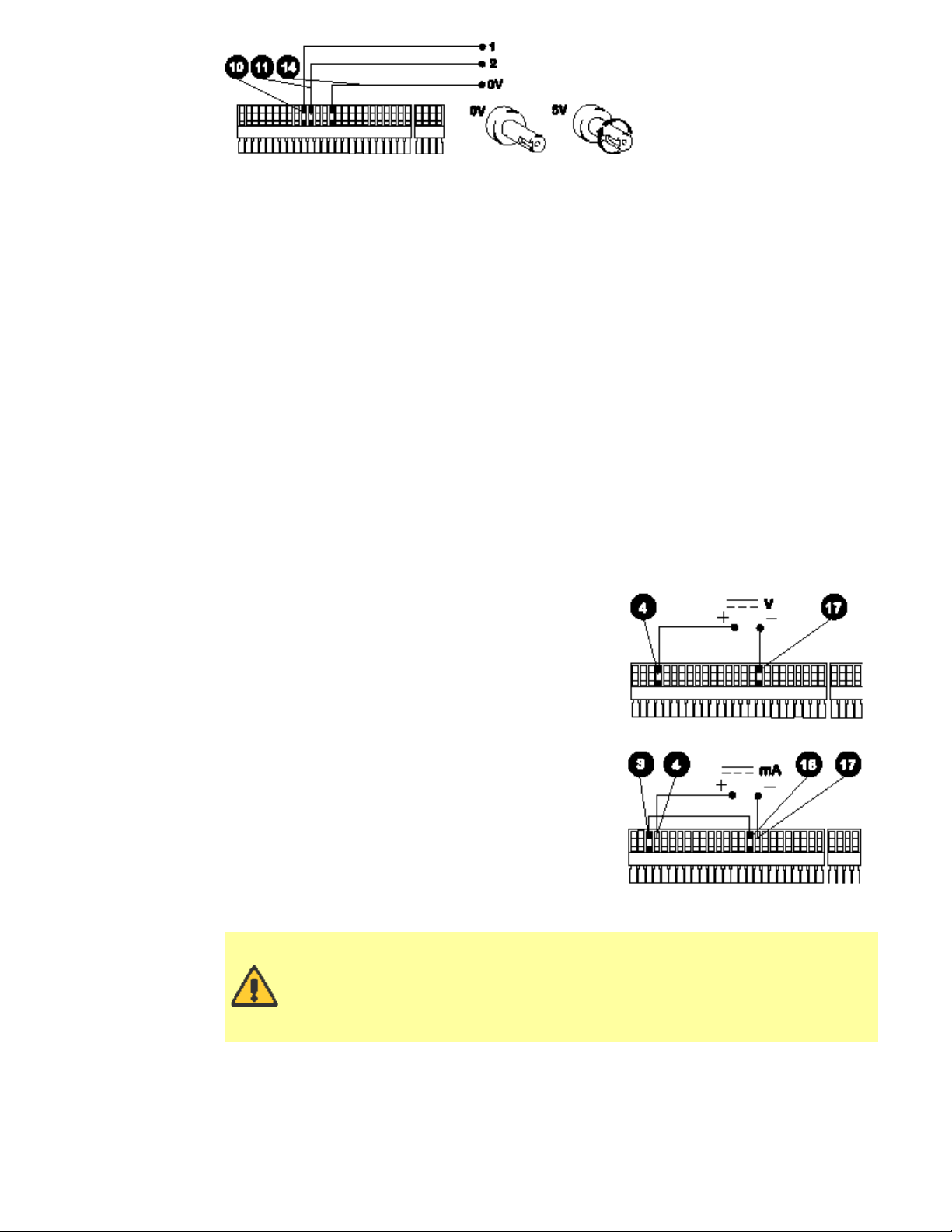
Auxiliary - Monitor the pump dosing or motor state/direction of rotation using 2 high (5V)
/low (0V) auxiliary signals outputted via the pumps 25 pin cage clamp connector. Auxiliary
signals can be used, for example, to command a turntable or conveyor to move when a
dose has been completed.
http://www.watson-marlow.it/pdfs-global/m-624Di-gb-01.htm[10/07/2012 13:59:15]
Page 8
Watson-Marlow Bredel E-Manuals
Line 1 can be set to change state every time the motor runs, or only when the motor runs
to dispense a dose. The signal can be set high or low when the motor runs. Line 2 changes
state when the pump direction is changed. The screens allow the signal to be set high or
low when the output shaft rotates clockwise.
Pump - When under RS232 control each individual pump must be identified. Select a
number from 1-16.
Max - Sets when the pump can be primed at maximum speed. Standard setting means
Max is enabled during Manual and Setup. Always enabled means the unit can be primed at
any time.
Default - Press Enter at "Yes" to restore factory defaults.
Autostart - If set to On when in Manual mode only, Autostart will allow the pump to
restart pumping automatically after power-up following a mains supply interruption. If set
to Off the pump will restart and return to the Main Menu.
Signal - Step to the desired process signal for analogue control and press Enter. Options
available are 4-20mA, 0-10mA, 0-20mA, 0-5V, 0-10V These signal ranges correspond to
0-200rpm speed control. A confirmation screen will verify settings chosen. If the signal
type required is not shown then use the "program" option to enter in the required signal
levels. The pump is controllable by an analogue process signal of up to 30V or 32mA. The
pump will provide an increasing flow rate for a rising control signal (non-inverted response)
or an increasing flow rate for a falling control signal (inverted response).
For voltage modes a stable, variable DC voltage
source can be used in conjunction with a DC
voltmeter, (max 30V DC). (Refer to the 25 pin cage
clamp connector wiring detail as an example of
control circuitry) Circuit impedance 100kW. Polarity
set for non-inverted response. Reverse polarity for
inverted response.
For current modes the same DC source can be used
in conjunction with a DC milliampere meter,
(maximum 32mA). (See 25 pin cage clamp connector
detail). Circuit impedance 250W. Polarity set for noninverted response. Reverse polarity for inverted
response.
Trim - This function will match the pump's signal
conditioner to the analogue process control signal if
they do not fully coincide. The user will be asked to
apply zero, 20% and the maximum voltage or
current that is required to be the control signal. Press
Enter after adjusting the process signal to each input level.
Never apply mains voltage across pins on the 25-pin cage clamp
connector. Up to 5V TTL may be applied to pins 7 and 5, but do not apply
voltage across any other pins. Failure to heed this warning could cause
permanent damage not covered by warranty. Do not use the mains
power switch to control the pump for a high repetition of stop starts.
The auto-control facility should be used.
Remote control
Pause dose This function will pause a dose for as long as a remote switch remains closed
then allows the dose to continue when the switch is opened. Under Manual mode it will
also act as a remote stop/start. Connect remote switch as in the Stop/Start diagram. Open
to run pump, close to pause or stop pump.
http://www.watson-marlow.it/pdfs-global/m-624Di-gb-01.htm[10/07/2012 13:59:15]
Page 9
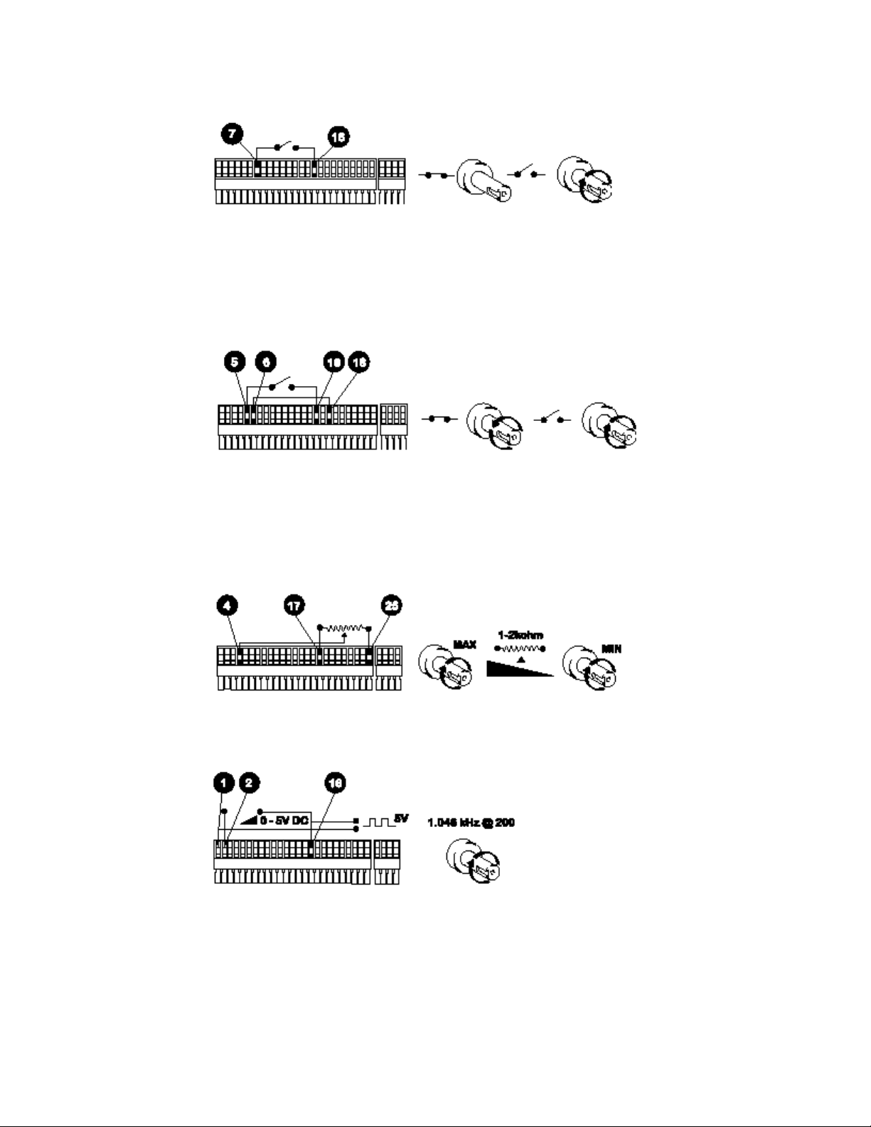
Watson-Marlow Bredel E-Manuals
Stop/Start Connect remote switch between pins 7 and 16 of the 25-pin cage clamp
connector. A TTL compatible logic input (Low 0V, High 5V) may be applied to pin 7. Low
input stops the pump, high input runs the pump. With no connection, the pump will default
to running.
Direction Connect remote switch between pins 5 and 16 and disable the front panel
reversing control by linking pins 6 and 18 of the 25 pin cage clamp connector. Open switch
for clockwise rotation, close for counter-clockwise. Alternatively a TTL compatible logic
input (Low 0V, High 5V) may be applied to pin 5. Low input will run the pump in a counterclockwise direction, High input in a clockwise rotation. No connection; the pump will default
to clockwise rotation.
Speed A remote potentiometer nominally 1kW and 2kW minimum 0.25W should be wired
as shown. When using a remote potentiometer, do not apply a voltage/current control
input signal at the same time. The pump must be calibrated for 0-12V analogue signal
control under the "PROGRAM" option of Signal in Setup. Alternatively, the potentiometer
may be used for the calibration procedure, instead of using the minimum and maximum
analogue process signal settings, if it is set to its minimum and maximum positions.
Tachometer output This facility can be used to indicate motor speed or total the number
of motor revolutions.
Footswitch A footswitch or handswitch will initiate the dose. The 624Di includes software
protection against spurious signals caused by bouncing of the switch contacts. This feature
is permanently activated (software setting fixed on "other") and only switches without
hardware debouncing should be used.
http://www.watson-marlow.it/pdfs-global/m-624Di-gb-01.htm[10/07/2012 13:59:15]
Page 10

Watson-Marlow Bredel E-Manuals
Care and maintenance
The only scheduled maintenance required for the 624Di is inspection of the motor brushes
and their replacement before their length is less than 6mm. The life of the brushes will
depend on the duty of the pump, but is expected to be a minimum of 3,000 hours at
maximum speed.
If the pump requires cleaning, use a mild solution of detergent in water after removing the
pumphead. Do not use strong solvents.
For gearbox rebuilds, use Lubriplate GR-132 (Bodine reference LG-23) only. This is a
lithium combination type thickener, NL GI No.1 grade, non-corrosive extreme pressure
lubricant. This product is water-resistant and resistant to a large degree to most other
contaminants.
Guard safety warnings
The 624Di will be remotely stopped and display a warning if the guard is opened during
operation. This safety feature is enabled under Manual, Dose, Analogue and RS232
operation.
Specification
Maximum rotor speed 200 rpm
Power supply 100-120/220-240V /1/ 50/60Hz
Control range 50:1
Power consumption 300 VA
Fuse rating Type T (anti-surge) 5A
Operating temperature range 5C to 40C
Storage temperature range -40C to 70C
Weight 605Di/R 24.75kg (55lbs)
Weight 605Di/L 30.75kg (68lbs)
Noise <72dBA at 1m
Standards EN60529 (IP55)
Machinery directive 98/37/EC EN60204-1
Low voltage directive 73/23/EEC EN61010-1
EMC directive 89/336/EEC EN50081-1/EN50082-1
Specific drive performance details such as loaded drive speed variation against mains
supply voltage fluctuation and drive stability from a cold start to normal operating
temperature are available on request. For further information please contact WatsonMarlow Technical Support Department.
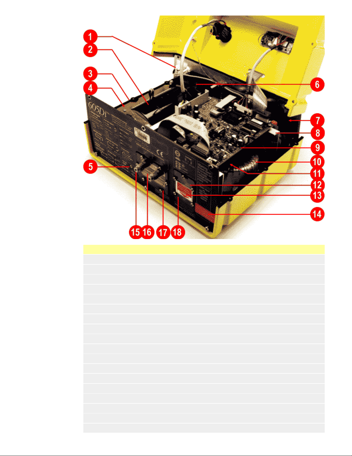
Drive spares
http://www.watson-marlow.it/pdfs-global/m-624Di-gb-01.htm[10/07/2012 13:59:15]
Page 11
Watson-Marlow Bredel E-Manuals
Number Spare Description
1 TM0020 Terminal block 10A 12-way
2 BM0015 Motor brush
3 MR0691S Gasket
4 MN0787M Tacho disc
5 FN0271 M4 screw
6 MG0605 Motor/gearbox
7 MRA0194A Pcb H bridge
8 MR0289S Chassis
9 MRA0269A Pcb cardinal
10 MRA0198A Transformer
11 FA0002 Filter
12 MR0669S Window cover
13 FS0043 Fuse 5A T type
14 CP0005 Blanking plug OD 20mm
15 CP0020 Blanking plug
16 MN1086S Window cover
17 MN1087S Window gasket
18 MR0771S Window gasket
http://www.watson-marlow.it/pdfs-global/m-624Di-gb-01.htm[10/07/2012 13:59:15]
Page 12

Watson-Marlow Bredel E-Manuals
620RE, 620RE4 and 620R Key safety information
Before opening the pumphead guard please ensure that the
following safety directions are followed.
For close-coupled drives, ensure that the pump is isolated from mains voltage.
Ensure that there is no pressure in the pipeline.
If a tube failure has occurred, ensure that any product in the pumphead has been
allowed to drain through the controlled waste to a suitable drain.
Ensure that protective clothing and eye protection are worn if hazardous products
are being pumped.
620RE, 620RE4 and 620R Safe-guarding
Primary safety on 620 series pumps is provided by the tool-lockable pumphead
guard. On electrically-powered cased 600 series pumps, secondary (backup)
protection is provided in the form of an electrical interlock which stops the pump if
the pumphead guard is opened (and only for so long as the guard is opened). The
electrical interlock on cased pumps should never be used as primary protection.
Always disconnect the mains power supply to the pump before opening the
pumphead guard.
Only primary protection through the tool-lockable guard is provided on pneumatically
powered 620 series cased pumps. Only primary protection through the tool lockable
pumphead guard is provided on 620 series pumps fitted with industrial AC motors,
but an interface kit to allow mains power to be switched by the pumphead guard
interlock is available as an extra-cost option.
620RE, 620RE4 and 620R Pumping conditions
Pressure and viscosity
All pressure values in this operating instruction, from which performance and life
figures have been calculated relate to peak pipeline pressures.
Although rated to 4 bar working pressure, this pump will generate in excess of 4 bar
working pressure if pipeline restrictions are in place. In instances where it is critical
that a working pressure of 4 bar is not exceeded, pressure relief valves should be
installed in the pipeline.
For pumping duties of 2-4 bar pressure, only close coupled pumps should be used,
fitted with 73 Shore hardness Marprene/Bioprene or standard STA-PURE tube
elements. "M" in the tube element’s product order code denotes suitability for high
pressure use.
When pumping duties of 0-2 bar pressure, use close coupled or cased pumps fitted
with 64 Shore hardness elements or the standard range of continuous peristaltic
pump tubing.
Viscosity handling is maximised by using 73 Shore hardness Marprene/Bioprene or
STA-PURE tube elements in the pumphead.
Ensure that there is always a minimum of one metre of smooth bore flexible tubing
connected to the discharge port of the pumphead. This will help minimise any
impulse losses and pulsation in the pipeline. This is especially important with viscous
fluids and rigid pipework.
620RE, 620RE4 and 620R Pump installation
A correctly engineered installation will promote the best possible tube life, so please ensure
that the following guidelines are followed:
Avoid tight pipeline bends, pipe reducers and excessive lengths of smaller bore
tubing than that in the pumphead, particularly in pipelines on the suction side.
Ensure that connecting pipe work and fittings are suitably rated to handle the
predicted pipeline pressure.
If rigid pipe work comes in close proximity to the pumphead, a drop out section of
pipe work will simplify tube replacement.
Ensure that the controlled waste blanking plug is in position if the controlled waste
port is not in use. See below.
http://www.watson-marlow.it/pdfs-global/m-624Di-gb-01.htm[10/07/2012 13:59:15]
Page 13

Watson-Marlow Bredel E-Manuals
It is advisable to use controlled waste pipe work if pumping hazardous, aggressive
or abrasive fluids or products which will harden in contact with air.
When connecting waste pipe work to the controlled waste port using the coupling
adaptor supplied, ensure that there is adequate clearance underneath the
pumphead. Waste pipe work should run to a suitable container or drain.
The leak detector installation procedure is included in the leak detector kit.
If unsure of an installation please contact your local Watson-Marlow Technical
Support Office for further assistance.
620RE, 620RE4 and 620R General operation
Opening the pumphead guard
Unlock the guard with a 5mm Allen key or a screw driver.
Open the guard to its full extent. This creates the maximum clearance between the
tube ports and guard to remove the tubing.
Engaging/disengaging the rollers
The extent of travel of the roller release levers is indicated below. Do not try and
force the levers beyond their normal extent of travel as this will damage the rotor.
To engage the rollers snap the roller release levers counter clockwise making sure
that the rollers locked out against the tubing. To disengage the rollers, snap the
release levers clockwise to their disengaged position. For high pressure tubing
elements or four roller pumpheads, the 5mm Allen key can be used to aid leverage
when engaging/disengaging the rollers with the release levers.
Make sure that fingers are clear of the front face of the rotor hub
when using the roller release levers.
Pre-load checks
Before loading tubing, ensure that all rollers rotate freely, that the tube ports and
location grooves are clean and that if in use, the controlled waste pipe work is free
of any obstructions.
Closing the pumphead guard and start-up
Ensure that the guard seal is clean, replacing it if necessary.
Ensure that the rollers are engaged and locked out against the tubing
Close the guard and push it against the track until the latch engages.
Connect suitable pipe work to the pumphead using the appropriate connectors for
the tube element.
Continuous tubing clamp location in 620R pumpheads
Select the appropriate tube clamp set for the tubing size to be used.
Locate the two "U"-shaped track clamp halves into the pumphead ports (The "U"shape ensures correct loading)
http://www.watson-marlow.it/pdfs-global/m-624Di-gb-01.htm[10/07/2012 13:59:15]
Page 14

Watson-Marlow Bredel E-Manuals
Locate the corresponding guard clamp halves which have raised "T" locating
sections, into the slots on the inner guard face above and below the guard hinge.
Push and slide into their locked position.
Closing the guard will align the two halves of the clamp around the tubing.
620RE and 620RE4 tube element loading
620RE element pumpheads are factory set to accept Watson-Marlow LoadSure tube
elements. Pumping performance will be adversely affected if LoadSure elements are
not used.
Disengage rollers
Locate one of the "D"-shaped flanges into the lower port. (The "D" flange ensures
that the element can only be loaded correctly).
Wrap the tube element around the disengaged rollers of the rotor.
Locate the second "D"-shaped flange into the upper port.
Ensure the flat face of each "D" flange sits flush to the flange sealing face of the
track.
Engage rollers
Close the guard and push it against the track until the latch engages.
Tube element loading
620RE, 620RE4 and 620R Continuous tube loading
620R continuous tubing pumpheads are factory set to accept Watson-Marlow 600
series 3.2mm wall tubing. Pumping performance will be adversely affected if
Watson-Marlow tubing is not used.
Select the tube clamp set which is correct for the tubing size to be used.
Disengage rollers
Locate one end of the tubing into the lower port "U" clamp and hold firmly in
position.
Wrap the tubing tightly around the retracted rollers, making sure that there is no
twisting through its length.
Locate the other end of the tubing into the upper port "U" clamp.
Hold both ends of the tubing in one hand maintaining tension around the retracted
rollers.
Engage rollers
Close the guard and push it against the track until the latch engages
Ensure that continuous tubing is not loosely clamped at the pumphead ports.
Ensure that when the pump is re-started all of the rollers have re-engaged. A roller
which has not re-engaged will "click" continuously. No damage will occur if this
happens but the roller should be re-engaged manually using the 5mm Allen key.
Please refer to the Troubleshooting section.
Continuous tube loading
http://www.watson-marlow.it/pdfs-global/m-624Di-gb-01.htm[10/07/2012 13:59:15]
Page 15

Watson-Marlow Bredel E-Manuals
620RE, 620RE4 and 620R Tube element or continuous tube removal
Unlock the guard and disengage the rollers.
Disconnect the tubing from the external pipeline.
Remove the tubing from the pumphead.
620RE, 620RE4 and 620R Maintenance
Scheduled maintenance
The stainless steel pumping rollers run on sealed bearings and do not require
lubrication.
Remove the rotor and lubricate the follower rollers and roller engaging mechanisms
with a lithium-based grease. This should be carried out every six months for
intermittent duties and every three months for 24 hour duties.
If fluid is spilled inside the pumphead, flush the pumphead out with water and mild
detergent as soon as possible. If specific cleaning agents are required to clean the
spillage, please consult Watson-Marlow Technical Support Office before proceeding,
in order to confirm chemical compatibility.
If the rotor needs to be removed, refer to the guidelines below.
Roller adjustment
620 pumpheads have provision for adjustment to reset the roller/track gap to compensate
for wear after extended service in arduous applications.
Roller/track gaps can only be accurately judged without tubing in the pumphead. The gap
http://www.watson-marlow.it/pdfs-global/m-624Di-gb-01.htm[10/07/2012 13:59:15]
Page 16

Watson-Marlow Bredel E-Manuals
should be 4.6mm for 3.2mm wall tubing and 5.5mm for LoadSure elements.
If the gap is more than 0.2mm greater than these dimensions, the following may be
carried out:
Note the number on the roller arm to which the engraved line on the hexagonheaded main roller pin corresponds.
Remove the circlip (snap-ring) and roller pin.
Relocate the main roller pin, resetting the engraved line to one number lower. For
example, if the engraved line was at "-1", reset it to "-2" to reduce the roller track
gap.
Ensure the roller pin is correctly seated into the roller arm thrust washer. Replace
the circlip.
Rotor removal and re-location
Remove the rotor cover and central locating bolt using a 5mm Allen key. Pull the
rotor off the keyed shaft, remove the key and clean thoroughly. Do not use tools to
lever the rear face of the rotor away from the inner face of the track, it should come
off by hand.
To replace the rotor, locate the key into the keyway and apply a thin layer of grease
over the shaft and key. Align the keyway of the rotor to the shaft key and slide the
rotor into position, ensuring that a positive "stop" is achieved and ensure that the
full length of the drive shaft is fitted into the rotor.
Do not force the rotor into position. The rotor will slide into place easily if correctly
aligned.
Tighten the hexagonal locating bolt to a nominal torque of 10Nm using a 5mm Allen
key.
The rotor bolt, which is impregnated with "Loctite 218" thread lock, should be
subjected to a maximum of three removals/relocations before renewal. To avoid
rotor bolt renewal after three removals, apply "Loctite 222" thread lock to the rotor
thread before relocation. This is critical to ensure prolonged, secure location of the
rotor hub to the drive shaft. Failure to complete this action will invalidate the
terms and conditions of the pumphead warranty.
Replace the rotor cover.
When closing the guard, check it does not make contact with the rotor. If it does, then the
rotor has been fitted incorrectly. Re-open the guard, remove and refit the rotor, and close
the guard.
http://www.watson-marlow.it/pdfs-global/m-624Di-gb-01.htm[10/07/2012 13:59:15]
Page 17

Watson-Marlow Bredel E-Manuals
Track removal (cased drives)
Remove the rotor.
Disconnect the controlled waste pipework if attached.
Loosen the two track-retaining screws using a screwdriver.
Withdraw the track slightly from the front plate to expose the guard interlock
connection.
Disconnect the guard interlock by manually removing the cable plug from the track.
Withdraw the track fully from the cased drive.
Track re-location (cased drives)
Ensure that the track is clean and that the spacer washer and gearbox boss
alignment rings are still in position.
Offer the track up to the front panel of the cased drive and re-connect the guard
interlock cable plug.
Fit the track over the gearbox boss.
Align the track horizontally so that the location holes are aligned with the front plate
threaded holes.
Tighten the two retaining screws using a screwdriver.
Re-connect the guard interlock controlled waste pipework if required.
620RE, 620RE4 and 620R CIP and SIP
General
Unlock the guard and disengage the rollers within the tube zone.
Close the guard and squeeze against the track until the latch clicks.
Observe a 1m safety area.
CIP
LoadSure tube elements and continuous tubing can be cleaned using CIP processes.
Ensure that the tubuing material is chemically compatible with the cleaning agent
that is to be used.
If cleaning agents are spilled over the pumphead, wash down immediately.
Ensure that controlled waste pipework is fitted to allow a safe release of cleaning
agent in the event of a tube failure.
SIP
Only STA-PURE tube elements can be used in a steam in place sterilisation
processes.
STA-PURE tubing elements can be sterilised to 3A Class two and FDA minimum
recommended standard which is 121C (250F) at 1bar (14.5 psi) saturated steam for
20 minutes.
Monitor the process continuously .
If a tube failure occurs, shut down the process. Do not touch the pumphead until a
20 minute cooling period has been observed.
http://www.watson-marlow.it/pdfs-global/m-624Di-gb-01.htm[10/07/2012 13:59:15]
Page 18

Watson-Marlow Bredel E-Manuals
Ensure a 20 minute acclimatisation period is observed before running the pump
following SIP.
Ensure that controlled waste pipework is fitted to allow a safe release of steam in
the event of a tube failure..
Ensure a 1m safety zone is maintained around the pumphead during SIP cycles.
Ensure that the pumphead door is closed and locked before SIP
cleaning commences.
620RE, 620RE4 and 620R Pumphead spares
Number Spare Description
1 Tube clamp pack: p/n 069.4101.000
2 MR2052C Oddie fastener
2 MR2053B Clip: Oddie retainer
2 MR2054T Oddie washer
2 SG0021 Oddie spring
2 CX0150 Oddie circlip (snap ring)
3 MRA0251A Track assembly (continuous pumphead) - includes guard
3 MRA0297A Track assembly (element pumphead) - includes guard
http://www.watson-marlow.it/pdfs-global/m-624Di-gb-01.htm[10/07/2012 13:59:15]
Page 19

Watson-Marlow Bredel E-Manuals
3 MR2000C Track
4 MRA0249A Roller assembly element pumphead
<4> MRA0250A Roller assembly continuous pumphead
5 MR2027T Controlled waste threaded fitting 620R
6 MR2028M Controlled waste port blanking plug
7 MR2018T Hinge pin
8 MR2055M Rotor cover
9 MR2021B Seal - guard
10 MR2002M Guard without latch and seal
11 MR2015T Follower roller spindle
12 CX0148 Roller assembly circlip (snap-ring) E type 6 dia
12 MR2014T Stainless steel roller spindle
12 MR2010T Thrust washer
13 MR2096T Controlled waste threaded fitting locking nut
14 MRA0320A Rotor assembly 2-roller element
14 MRA0321A Rotor assembly 4-roller element
14 MRA0322A Rotor assembly 2-roller continuous
15 MR2058B Grommet - door switch
16 XX0220 Key - metal
17 MR2029T Cased drive MG605 shaft/rotor hub spacer
18 MR2059T Adaptor - Bodine (white polypropylene ring)
19 FN0488 Cased drive track locating screw M6x10 locating bolt
20 FN0523 Close-coupled track locating screw M6x20 locating bolt
21 FN0581 Rotor locating washer M6
22 FN0520 Rotor locating bolt M6 x 25
23 TT0006 5mm Allen key
24 MA0017 Guard magnet
CN0187 Plug blanking 10.72M
MRA0268A Cased drive door switch assembly
MRA0279A Close-coupled door switch assembly
625L Pumphead
The twin offset track design of the 625L utilises 4.0mm wall double-Y tube elements to
overcome pulsation for accurate dosing and dispensing. The 625L accepts Silicone and
Marprene tubing up to 16.0mm bore. Use 4.0mm wall tube for transfer for the highest
performance and improved viscous fluid handling.
Alternatively the 625L will run with two separate tubes although some channel to channel
variance and minimal pulsation may be experienced. For separate tube fitting or twin tube
inlet to single tube outlet fitting tube clamping blocks must be used.
625L Installation
Remove the mounting plate cover and track from the 625L. Locate 625L to pump. Tighten
top and bottom mounting plate screws. To remove the pumphead lift off the mounting
plate cover and track, loosen the top and bottom mounting plate securing screws and ease
pumphead away from the pump.
http://www.watson-marlow.it/pdfs-global/m-624Di-gb-01.htm[10/07/2012 13:59:15]
Page 20

Watson-Marlow Bredel E-Manuals
625L Tube loading
Double-Y element
Lift the track locating levers and remove the track. Locate one end of double-Y element
over one of the 625L clamping pegs. Stretch the element over the rotor and locate the
other end of the element over the second 625L clamping peg. Replace the track and push
down the track locating levers. (See pumphead installation).
Twin inlet tubes
Lift the track locating levers and remove the track. Twist and remove the 625L inlet
clamping peg. Connect the twin inlet tubes and outlet tube using the appropriate Y-piece
connector and clamps. Fit the inlet tubes into the correct size clamping block. Locate the
clamping block onto the 625L (push down and twist locking fastener to secure). Stretch the
tubes over the rotor and locate the Y-piece end of the element over the second 625L
clamping peg. Replace the track and push down the track locating levers.
Two independent tubes
Lift the track locating levers and remove the track. Twist and remove the 625L clamping
pegs. Fit the two tubes into the correct size clamping blocks. Distance between blocks =
230mm for up to 8.0mm bore; 240mm for 12.0mm and 16.0mm bore. Fit the inlet tube
clamping block to the 625L. Stretch the tubes over the rotor and fit second tube clamping
block to the 625L. Replace the track and push down the track locating levers. When using
Marprene it is important to check the distance between the clamping blocks after 30
minutes running time.
http://www.watson-marlow.it/pdfs-global/m-624Di-gb-01.htm[10/07/2012 13:59:15]
Page 21

Watson-Marlow Bredel E-Manuals
625L Care and maintenance
Check all moving parts for freedom of movement occasionally. If aggressive fluids are spilt
onto the pumphead, clean using a mild detergent only.
625L Track adjustment
The track is set for 4.0mm wall tubing up to 16.0mm bore. Alteration of this setting using
the pan head screws may be necessary to optimise performance if non-standard tubing is
used. The factory setting is 20.3mm vertically from the rotor side of the sprung track to
the top of the track cover.
625L Pumphead spares
Number Spare Description
1 MRA0141A Track assembly
2 MR0851S Cover plate
3 SW0050 Proximity switch
4 MRA0143A Adaptor
5 BB0018 Shaft bearing
http://www.watson-marlow.it/pdfs-global/m-624Di-gb-01.htm[10/07/2012 13:59:15]
Page 22

Watson-Marlow Bredel E-Manuals
6 MRA0150A Rotor assembly
7 MR0850S Front plate
8 MRA0144A Tuibe locating peg
069.4001.000 Tube clamp set
625L Operation
User
decision
Instruction
reference
Quick start
A. Switch on power to drive.
B. User decision to calibrate.
C. Indication of head and tubing to which pump is currently calibrated.
D. If set-up not correct change existing set-up.
E. Select head and tubing.
F. Choose the pumphead required.
G. Choose the tube size. Selection confirmed.
H. Select Dose from Main menu.
I. Set a new dose program.
J. Set the volume or weight to be dosed.
K. Set the time interval between doses.
L. Set the number of doses to be dispensed.
M. Set the pump speed or volume flow rate.
N. Proceed to dose with using set parameters.
O. Verification of interval between doses and pump speed.
P. Verification of volume and number of doses, press Start.
Pump screen
display
Terminal Operation Flow
connector
Keypad functions
Manual
input
Quick start
http://www.watson-marlow.it/pdfs-global/m-624Di-gb-01.htm[10/07/2012 13:59:15]
Page 23

Watson-Marlow Bredel E-Manuals
Recall program
Q. Recall previously set program from memory.
R. Select required program.
S. Verification of selected dose program.
T. Verification of interval between dose shots and pump speed.
U. User decision to accept chosen program. Repeated verification of dose parameters.
Recall program
http://www.watson-marlow.it/pdfs-global/m-624Di-gb-01.htm[10/07/2012 13:59:15]
Page 24

Watson-Marlow Bredel E-Manuals
Record program
V. Pump starts.
W. User decision to record a set of dose program settings.
X. Select the memory location.
Y. Small case letters indicate an empty memory location.
Z. Verification of saved dose program.
A1. Verification of time interval between dose shots and pump speed.
B1. Verification of volume and number of doses, press Start
C1. Pump starts dosing.
Record program
http://www.watson-marlow.it/pdfs-global/m-624Di-gb-01.htm[10/07/2012 13:59:15]
Page 25

Watson-Marlow Bredel E-Manuals
Calibration
D1. Indication of previous calibration (if completed).
E1. Decision to calibrate pump to new pumphead and tubing size.
F1. Select the pumphead and tubing which is fitted to pump.
G1. Confirmation of user selections. Maximum pump speed is governed by pumphead
fitted.
H1. Decision to calibrate pump using a calibration dose.
I1. Enter calibration speed and direction.
J1. Pump starts to calibrate. Press stop when ready.
K1. After 15 seconds pump will prompt user to stop calibrating.
L1. Measure and then enter the actual volume that has been dosed during calibration.
M1. Indication of pumphead, ml/rev and maximum rpm which is governed by the
pumphead.
Calibration
http://www.watson-marlow.it/pdfs-global/m-624Di-gb-01.htm[10/07/2012 13:59:15]
Page 26

Watson-Marlow Bredel E-Manuals
Dose (1)
N1. Switch on pump and Main menu is called .
O1. User chooses dose option.
P1. Recal program option available only if program has previously been saved.
Q1. User recalls a preset program. Large case letters denote a stored program
R1. Decision to set a new dose program.
S1. Enter dose volume in ml (0.001L<Dose<9999L).
T1. Enter dose weight in grams (0.001kg<Dose<9999kg).
U1. Set the specififc gravity of the fluid (Maximum 5.0).
V1. Dose is too small for pump (Minimum dose set should require 5 rotor revolutions).
W1. Dose is too small for tubing.
X1. Dose is ok for setup.
Y1. Set time interval between doses (0.1s<Time<6550s).
Z1. Set total number of doses (up to 9999 doses).
Dose (1)
http://www.watson-marlow.it/pdfs-global/m-624Di-gb-01.htm[10/07/2012 13:59:15]
Page 27

Watson-Marlow Bredel E-Manuals
Dose (2)
A2. Set drive speed.
B2. Set volume flow rate.
C2. Set direction of rotation of drive.
D2. Proceed to dose or save program.
E2. Proceed to dose.
F2. Record program.
G2. Set the memory location for the dose parameters.
H2. Choosing a capital letter will call the existing program settings within that memory
location.
http://www.watson-marlow.it/pdfs-global/m-624Di-gb-01.htm[10/07/2012 13:59:15]
Page 28

Watson-Marlow Bredel E-Manuals
I2. Choosing a small case letter will call the dose settings to be saved.
J2. Indication of dosing interval and pump speed.
K2. Overwrite existing program or save to different memory location.
L2. Decision to choose new memory location.
M2. Decision to overwrite existing program.
Dose (2)
Dose (3)
N2. Dose program called for use.
O2. Indication of dosing time interval and pump speed.
P2. Volume/weight set and number of dose shots. Press start.
Q2. Pump starts dosing run.
R2. Option to restart dosing, re-calibrate pump or exit from dosing.
S2. Restart dosing.
http://www.watson-marlow.it/pdfs-global/m-624Di-gb-01.htm[10/07/2012 13:59:15]
Page 29

Watson-Marlow Bredel E-Manuals
T2. Decision to re-calibrate pump.
Dose (4)
U2. Prompt to enter volume which pump is physically dosing during each shot.
V2. Measure and then enter manually the actual volume/weight which has been dosed.
W2. Default tolerance limit of +/-25% of pre-set dose volume on actual dosing volume
entered.
X2. Decision to exit from dose program.
Y2. The dosing batch is paused. Option to restart or stop.
Z2. Decision to re-start dosing.
A3. Decision to stop dosing.
B3. Indication of volume/weight dosed and number of doses completed.
C3. Option to restart dosing or return to Main menu.
D3. Return to Main menu.
E3. Start dosing.
F3. Unsaved dose settings will be called.
G3. Saved dose setting will be called.
H3. Indication of dose program which has been called.
I3. Dosing time interval and start prompt.
Dose (3)
http://www.watson-marlow.it/pdfs-global/m-624Di-gb-01.htm[10/07/2012 13:59:15]
Page 30
Watson-Marlow Bredel E-Manuals
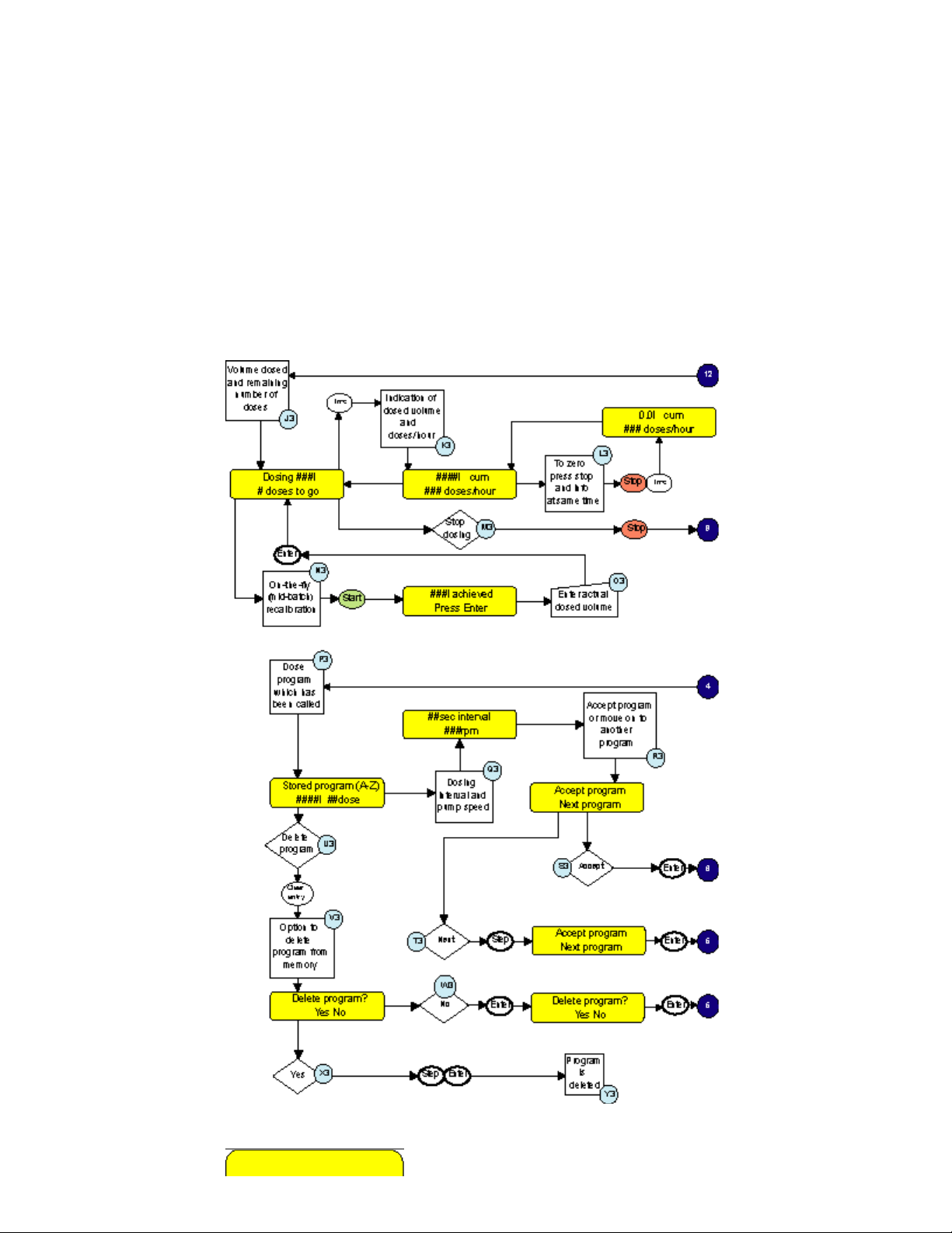
Programs and setup lost
J3. Indication of volume/weight dosed and number of doses remaining.
K3. Indication of volume/weight dosed and number of doses/hour.
L3. Option to zero the cumulative volume register.
M3. Decision to stop dosing.
N3. On-the-fly (mid batch) re-calibration facility.
O3. Enter actual volume dosed and pump will re-calibrate itself over 5 dose shots.
P3. Indication of dose volume/weight and number of doses in program called.
Q3. Verification of time interval between dose shots and pump speed.
R3. Accept called program for dose or choose another program from memory.
S3. Decision to accept program.
T3. Move to next program in memory.
U3. Decision to delete program from memory.
V3. Option to delete program from memory.
W3. Decision to not delete program.
X3. Decision to delete program.
Y3. Program is deleted.
Dose (4)
625L Error Messages
http://www.watson-marlow.it/pdfs-global/m-624Di-gb-01.htm[10/07/2012 13:59:15]
Page 31

Watson-Marlow Bredel E-Manuals
press enter
This screen indicates corruption of the RAM or that the EPROM has been changed. In either
case pressing Enter will re-initialise the RAM and clear the error.
check drive and
setup now
This screen indicates that the motor has stalled or that a loss of tachometer pulses has
been selected. Clear the cause of stalling and power the pump off and on. If the error
persists seek qualified assistance.
Rs232 parameter
error
Signifies an illegal command string when under RS232 control.
data corrupted!
recalibrate
A corruption of data has been detected. Switch unit off and on. Re-calibrate using Head
and Tubing first followed by a calibration dose if necessary.
620RE, 620RE4 and 620R Technical data
Performance envelope of the 620R, 620RE and 620RE4 mark II rotor
Flow rates
Flow rates for the 624Di/R and 624Di/L were obtained pumping water at 20C with
negligible suction and delivery pressures (unless otherwise stated). Where an application is
critical, the flow rate should be determined under operating conditions. The important
factors are suction and delivery pressures, temperature and fluid viscosity.
620RE, 620RE4 and 620R Flow rates
Tube bore Tube number - # rpm Pressure (+) Suction (-)
Note: Flow rates quoted have been rounded for simplicity, but are accurate to within 5% well within the normal tubing tolerance variation of flow rate. They should therefore be
http://www.watson-marlow.it/pdfs-global/m-624Di-gb-01.htm[10/07/2012 13:59:15]
Page 32

Watson-Marlow Bredel E-Manuals
taken as a guide. Real flow rates in any application must be determined empirically.
620R
Flow rates: Marprene, Bioprene
mm 6.4 9.6 12.7 15.9
inch 1/4 3/8 1/2 5/8
# 26 73 82 184
4-200 (l/min) 0.05 - 2.6 0.10 - 5.0 0.16 - 8.0 0.21 - 10
4-200 (USGPM) 0.01 - 0.7 0.03 - 1.3 0.04 - 2.1 0.06 - 2.6
Flow rates: Silicone
mm 6.4 9.6 12.7 15.9
inch 1/4 3/8 1/2 5/8
# 26 73 82 184
4-200 (l/min) 0.05 - 2.4 0.11 - 5.4 0.17 - 8.4 0.22 - 14
4-200 (USGPM) 0.01 - 0.6 0.03 - 1.4 0.04 - 2.2 0.06 - 3.6
Flow rates: Neoprene, STA-PURE
mm 6.4 9.6 12.7 15.9
inch 1/4 3/8 1/2 5/8
# 26 73 82 184
4-200 (l/min) 0.05 - 2.4 0.10 - 5.0 0.16 - 8.0 0.24 - 12
4-200 (USGPM) 0.01 - 0.6 0.03 - 1.3 0.04 - 2.1 0.06 - 3.2
620RE
Flow rates: Marprene TM, Bioprene TM
mm 12 17
4-200 (l/min) 0.15 - 7.4 0.24 - 12
4-200 (USGPM) 0.04 - 2.0 0.06 - 3.1
Flow rates: Marprene TL, Bioprene TL
mm 12 17
LoadSure LoadSure
LoadSure LoadSure
4-200 (l/min) 0.15 - 7.4 0.27 - 13
4-200 (USGPM) 0.04 - 2.0 0.07 - 3.6
Flow rates: Silicone
mm 12 17
4-200 (l/min) 0.15 - 7.7 0.24 - 12
4-200 (USGPM) 0.04 - 2.0 0.06 - 3.2
Flow rates: Neoprene, STA-PURE
http://www.watson-marlow.it/pdfs-global/m-624Di-gb-01.htm[10/07/2012 13:59:15]
LoadSure LoadSure
Page 33

Watson-Marlow Bredel E-Manuals
mm 12 17
LoadSure LoadSure
4-200 (l/min) 0.16 - 8.0 0.29 - 14
4-200 (USGPM) 0.04 - 2.1 0.08 - 3.8
620RE4
Flow rates: Marprene TM, Bioprene TM
mm 12 17
LoadSure LoadSure
4-200 (l/min) 0.13 - 6.3 0.16 - 8.2
4-200 (USGPM) 0.03 - 1.7 0.04 - 2.2
Flow rates: Marprene TL, Bioprene TL
mm 12 17
LoadSure LoadSure
4-200 (l/min) 0.13 - 6.3 0.19 - 9.4
4-200 (USGPM) 0.03 - 1.7 0.05 - 2.5
Flow rates: Silicone
mm 12 17
4-200 (l/min) 0.13 - 6.6 0.17 - 8.5
4-200 (USGPM) 0.03 - 1.7 0.05 - 2.3
Flow rates: Neoprene, STA-PURE
mm 12 17
4-200 (l/min) 0.14 - 6.8 0.20 - 10
4-200 (USGPM) 0.04 - 1.8 0.05 - 2.7
Dimensions in mm
624Di/R
LoadSure LoadSure
LoadSure LoadSure
http://www.watson-marlow.it/pdfs-global/m-624Di-gb-01.htm[10/07/2012 13:59:15]
Page 34

Watson-Marlow Bredel E-Manuals
624Di/L
620R product codes
mm inch # Marprene Bioprene
6.4 1/4 26 902.0064.032 903.0064.032 910.0064.032 913.0064.032
9.6 3/8 73 902.0096.032 903.0096.032 910.0096.032 913.0096.032
12.7 1/2 82 902.0127.032 903.0127.032 910.0127.032 913.0127.032
15.9 5/8 184 902.0159.032 903.0159.032 910.0159.032 913.0159.032
mm inch # STA-PURE Neoprene Butyl Tygon
6.4 1/4 26 960.0064.032 920.0064.032 930.0064.032 950.0064.032
9.6 3/8 73 960.0096.032 920.0096.032 930.0096.032 950.0096.032
12.7 1/2 82 960.0127.032 920.0127.032 930.0127.032 950.0127.032
15.9 5/8 184 960.0159.032 920.0159.032 930.0159.032 950.0159.032
Gore
Peroxide
silicone
Platinum
silicone
http://www.watson-marlow.it/pdfs-global/m-624Di-gb-01.htm[10/07/2012 13:59:15]
Page 35

Watson-Marlow Bredel E-Manuals
mm inch # Fluorel fluoroelastomer
/PTFE
6.4 1/4 26 970.0064.032 965.0064.032
9.6 3/8 73 970.0096.032 965.0096.032
12.7 1/2 82 970.0127.032 965.0127.032
15.9 5/8 184 970.0159.032 965.0159.032
620RE and 620RE4 LoadSure product codes
12mm
DIN 15
STA-PURE 960.0120.PFD 960.0120.PFT 960.0170.PFD 960.0170.PFT
Gore
fluoroelastomer
/PTFE
Bioprene TM 903.M120.PFD 903.M120.PFT 903.M170.PFD 903.M170.PFT
Bioprene 903.0120.PFD 903.0120.PFT 903.0170.PFD 903.0170.PFT
Platinum
silicone
Marprene TM 902.M120.PPC 902.M170.PPC
Marprene 902.0120.PPC 902.0170.PPC
Peroxide
silicone
Neoprene 920.0120.PPC 920.0170.PPC
620R dosing guidelines
965.0120.PFD 965.0120.PFT 965.0170.PFD 965.0170.PFT
913.0120.PFD 913.0120.PFT 913.0170.PFD 913.0170.PFT
12mm
Cam and Groove
3/4in
910.0120.PPC 910.0170.PPC
12mm
Tri-clamp 3/4in
17mm
Cam and Groove
3/4in
17mm
DIN 15
17mm
Tri-clamp
3/4in
L ? s ?
ml (± 1%) 50 100 250 500 1000 2500
mm
~ s (sec) 1.5 1.6 2.2 2.8 5.2 12.5
ml (± 2%) 50 100 250 500 1000 2500
mm
~ s (sec) 1.0 1.1 1.6 2.8 5.2 12.5
625L dosing guidelines
L ? s ?
ml (± 0.5%) 200 500 1000 2000 5000
mm
~ s (sec) 1.8 3.5 7.1 14.1 35.3
ml (± 1%) 200 500 1000 2000 5000
mm
~ s (sec) 1.4 3.5 7.1 14.1 35.3
ml (± 2%) 200 500 1000 2000 5000
6.4 9.6 12.7 15.9 15.9 15.9
9.6 12.7 15.9 15.9 15.9 15.9
12.0 16.0 16.0 16.0 16.0
16.0 16.0 16.0 16.0 16.0
http://www.watson-marlow.it/pdfs-global/m-624Di-gb-01.htm[10/07/2012 13:59:15]
Page 36

Watson-Marlow Bredel E-Manuals
mm
~ s (sec) 1.4 3.5 7.1 14.1 35.3
625L product codes
< tr>
mm
8.0 960.E080.K40 965.E080.K40 913.AE80.K40 902.E080.K40
12.0 960.E120.K40 965.E120.K40 913.A12E.K40 902.E120.K40
16.0 960.E160.040 965.E160.040 913.A16E.040 902.E160.040
625L (4mm) product codes
< tr>
mm
8.0 903.0080.040 913.A080.040 902.0080.040
12.0 903.0120.040 913.A120.040 902.0120.040
STA-PURE
Bioprene
16.0 16.0 16.0 16.0 16.0
Gore
fluoroelastomer
Platinum
silicone
Platinum
silicone
Marprene
Marprene
16.0 903.0160.040 913.A160.040 902.0160.040
625L Y-piece product codes
mm
8.0 999.3096.K00
12.0 999.3120.K00
16.0 CN0125
Trademarks and disclaimer
Watson-Marlow, Loadsure, Bioprene and Marprene are trademarks of Watson-Marlow
Limited.
TYGON is a trademark of the Saint Gobain Performance Plastics Company.
STA-PURE is a trademark of W L Gore & Associates.
The information contained in this document is believed to be correct but Watson-Marlow
Limited accepts no liability for any errors it contains, and reserves the right to alter
specifications without notice.
Patient-connected use: warning
Warning, These products are not designed for use in, and should not be used for patient
connected applications.
Publication history
m-624di-gb-01.htm: Watson-Marlow 624Di
First electronically published 12 02.
Decontamination certificate
In compliance with the UK Health and Safety at Work Act and the Control of Substances
Hazardous to Health Regulations, you are required to declare the substances which have
been in contact with product(s) you return to Watson-Marlow or its subsidiaries or
distributors. Failure to do so will cause delays. Please ensure that you fax us this form and
receive an RGA (Returned Goods Authorisation) before you despatch the product(s). A
copy of this form must be attached to the outside of the packaging containing the
http://www.watson-marlow.it/pdfs-global/m-624Di-gb-01.htm[10/07/2012 13:59:15]
Page 37

Watson-Marlow Bredel E-Manuals
product(s). Please complete a separate decontamination certificate for each product.
Your name Company
Address
Postcode/zip Country
Telephone Fax
Product type Serial number
To speed the repair, please
describe all known faults
You are responsible for cleaning and decontaminating the product(s) before return.
The product has ...
Names of chemicals
handled with product(s)
Precautions to be taken in
handling these chemicals
Action to be taken in the
event of human contact
Signature
Been used Not been used
If the product has been used, please complete all the following sections. If the product has
not been used, please just sign this form.
I understand that the personal data collected will be kept confidentially in accordance with
the UK Data Protection Act 1998.
RGA number
Your position
Date
Please print out, sign and fax to Watson-Marlow Pumps at +44 1326 376009.
http://www.watson-marlow.it/pdfs-global/m-624Di-gb-01.htm[10/07/2012 13:59:15]
 Loading...