

Page 1

621 Trio
621tr-gb-02.pdf
Page 2
Declarations
Declaration of
conformity
Declaration of
Incorporation
Responsible person: Dr R Woods, Managing Director, Watson-Marlow Limited, Falmouth, Cornwall TR11 4RU, England.
Telephone +44 (0) 1326 370370 Fax +44 (0) 1326 376009.
When this pump unit is used as a stand alone pump it complies with: Machinery Directive
98/37/EC EN60204-1, Low Voltage Directive 73/23/EEC EN61010-1, EMC Directive 89/336/EEC
EN50081-1/EN50082-1.
When this pump unit is to be installed into a machine or is to be assembled with other
machines for installations, it must not be put into service until the relevant machinery has been
declared in conformity with the Machinery Directive 98/37/EC EN60204-1.
T wo year warranty
Watson-Marlow Limited warrants, subject to the conditions below, through either Watson-Marlow Limited, its subsidiaries, or its
authorised distributors, to repair or replace free of charge, including labour, any part of this product which fails within two years of
delivery of the product to the end user. Such failure must have occurred because of defect in material or workmanship and not as
a result of operation of the product other than in accordance with the instructions given in this manual.
Conditions of and specific exceptions to the above warranty are:
• Consumable items such as tubing and rollers are excluded.
• Products must be returned by pre-arrangement carriage paid to Watson-Marlow Limited, its subsidiaries, or its authorised
distributor.
• All repairs or modifications must have been made by Watson-Marlow Limited, its subsidiaries, or its authorised distributors or
with the express permission of Watson-Marlow Limited, its subsidiaries, or its authorised distributors.
• Products which have been abused, misused, or subjected to malicious or accidental damage or electrical surge are excluded.
Warranties purporting to be on behalf of Watson-Marlow Limited made by any person, including representatives of Watson-Marlow
Limited, its subsidiaries, or its distributors, which do not accord with the terms of this warranty shall not be binding upon WatsonMarlow Limited unless expressly approved in writing by a Director or Manager of Watson-Marlow Limited.
Information for returning pumps
Equipment which has been contaminated with, or exposed to, body fluids, toxic chemicals or any other substance hazardous to
health must be decontaminated before it is returned to Watson-Marlow or its distributor.
A certificate included at the rear of these operating instructions, or signed statement, must be attached to the outside of the shipping
carton.
This certificate is required even if the pump is unused. If the pump has been used, the fluids that have been in contact with the pump
and the cleaning procedure must be specified along with a statement that the equipment has been decontaminated.
Safety
In the interests of safety, this pump and the tubing selected should only be used by competent, suitably trained personnel after they
have read and understood this manual, and considered any hazard involved.
Any person who is involved in the installation or maintenance of this equipment should be fully competent to carry out the work. In
the UK this person should also be familiar with the Health and Safety at Work Act 1974.
Fundamental work with regard to lifting, transportation, installation, starting-up, maintenance
and repair should be performed by qualified personnel only. Make absolutely sure that no voltage
is applied at all whilst work is being carried out on the geared motor. The motor must be secured
against accidental start up.
2
Page 3
500 and 600 series close coupled pumps
Details on the use, operation, maintenance and spare parts for the 500 and 600 series close coupled pumps can be found in the
accompanying manual PB 0279.
T rio cose coupled pump operating instructions
Trio close coupled pumps combine a pumphead, motor/ gearbox and integral inverter into a robust IP55 pump.
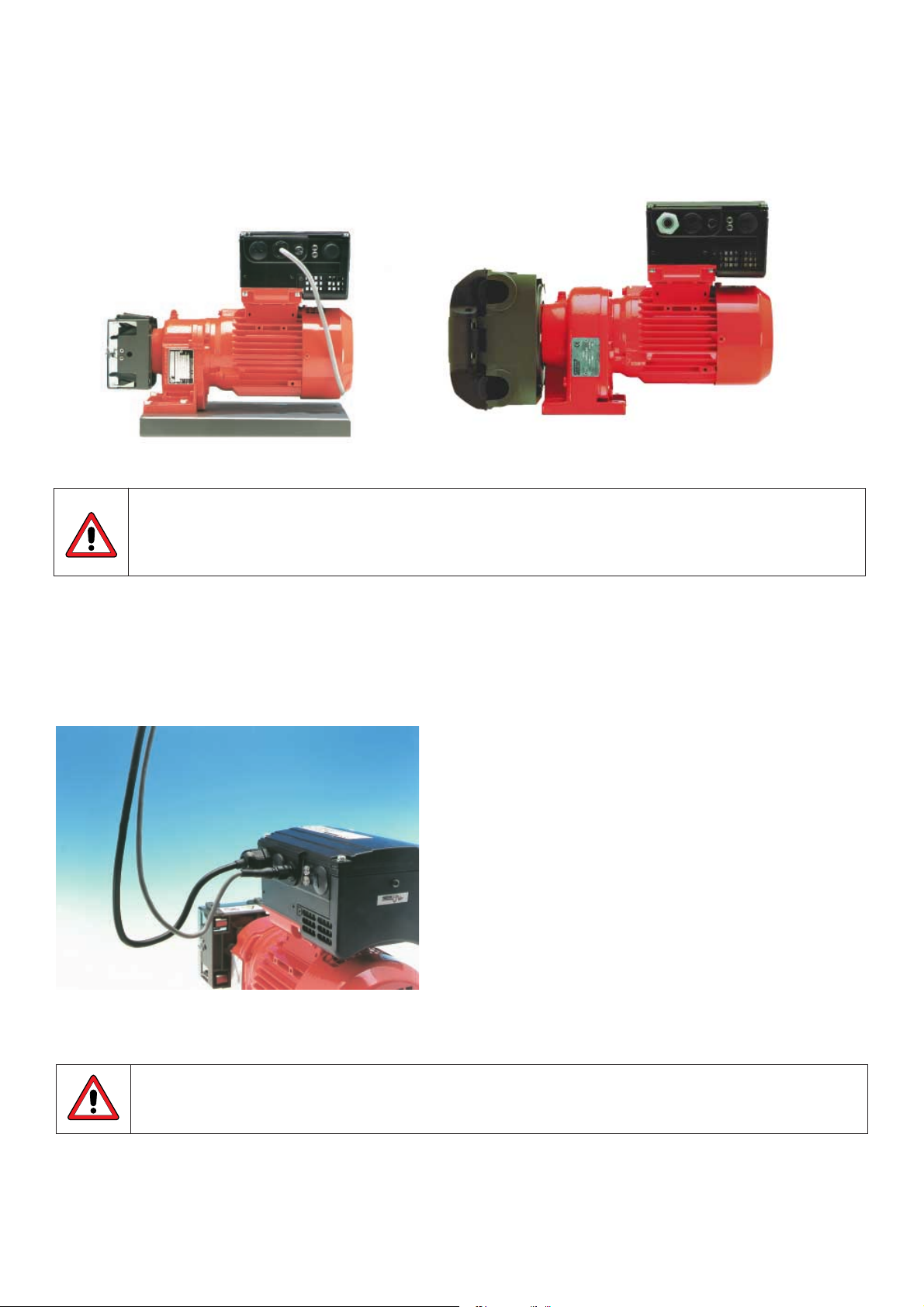
500 and 600 series Trio close coupled pumps
This equipment contains hazardous voltages (at mains potential) inside the pump. If access is required, turn
the power off and wait one minute so that the dc-link capacitors can discharge. Some parameter settings
can start the motor automatically after a mains failure. The Trio inverter is not to be used as an emergency
stop mechanism, a circuit breaker must be used.
Wiring connection details
Remove the four M4 cross head screws on the Trio’s cover to access the electrical terminals (see Fig. 2).
Note: A ‘drip loop’ is recommended when connecting the mains and control cables (see Fig. 1).
Fig. 1 Connecting mains cables and control cable with a drip loop.
The printed circuit board is particularly sensitive to static electricity. For this reason, avoid touching the
boards or components with your hands or metal objects.
3
Page 4
Mains cable connections
Ensure that the power source supplies the correct voltage and is designed for the rated current. Use a circuit-breaker with a 10A
current rating between the power supply and Trio. Use Class 1 60/75°C copper wire only with a cross sectional area of 1mm. If
crimp terminals are used they must be insulated. If crimps are not used, the strip length must not exceed 5mm. Feed the power
cable into the inverter via the gland hole nearest to the motor shaft using a PG16 gland. Connect the power leads to terminals L1,
L2 and the separate earth. Use a 4-5mm cross head screwdriver to tighten the terminal screws.
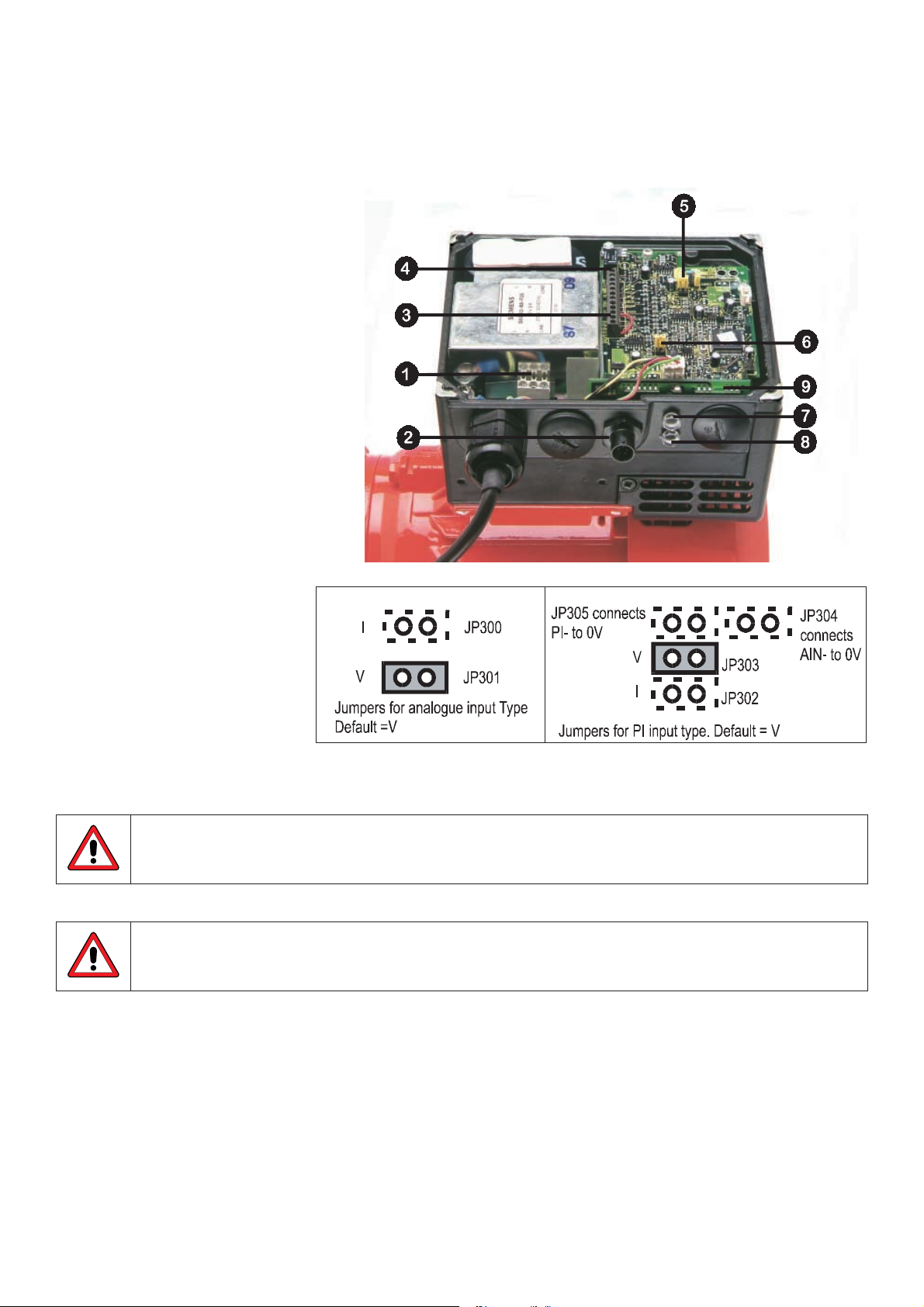
1 Mains connector
2 OPM2 Hand Held controller connector
3 Control terminal 1
4 Control terminal 12
5 JP305 - JP302
6 JP300 - JP301
7 LED (green)
8 LED (yellow)
9 Internal Potentiometer R314
Fig 2. Electrical connection drawing
Ensure that the following tightening torques are used: Access cover retaining screws:
2.5Nm, Gland hole covers: 1.0Nm, Mains connector screws: 1.0Nm, Control connector PL700: 0.4Nm.
Check the supply voltage is correct for the inverter used by referring to the rating label.
Control cable connections
The control and power supply cables (max 1mm diameter) must be laid separately. They must not be fed
through the same cable conduit/ trunking.
Use screened cable for the control lead.
Feed the control cable into the inverter via the appropriate gland hole (see Fig. 2). Connect the control wires in accordance with the
information in Fig. 3 and 4 (also see Fig. 1).
IMPORTANT: A wire link will have been factory fitted between control terminals 5 (DIN1) and 1 (P10+) to enable the Trio to
operate when control potentiometer R314 is used. The wire link must be removed when operation via a run/
stop switch is required.
Note that the optional potentiometer fitted as an analogue set point shown in Fig. 3 assumes that jumper JP304 is connecting 0V
(pin 2) to AIN- (pin 4). Also, P15+ can be used as an alternative to P10+ for the digital inputs.
4
Page 5

Relay
(24 V dc 1.0 A max)
JP305 JP304
DIN3
P15+
DIN2 DIN1 AIN-
AIN+PI+ PI-
0V P10+
12 11
(0-10Vor0-20mA)
10 9 8
PI Power
Supply (+15V
max 50 mA)
PI +ve Input
7
Digital
Inputs
(7.5 - 33V,
max 5 mA)
65
3
4
Analogue
Input
0/2-10Vor
0/4 - 20mA)
Fig. 3: Control Terminal Connections
21
Power for
Digital &
Analogue Inputs
(+10 V max 10mA)
Fig. 4: Control wire connections
Refit the cover and tighten the four securing screws.
Operating Information
The equipment must not be switched on until after its cover has been fitted and the cover screws have been
tightened to the correct torque. (see fig 2.) When using the external analogue control the jumpers (Fig 2) must
be correctly set and the analogue signal type selected (PO23) before enabling the analogue input with P006.
If this is not done, the motor may start without warning.
The inverter does not have a mains power switch and is therefore live when the mains supply is connected.
When supplied, the inverter has a frequency setpoint range of between 5Hz and 50Hz.
Basic Operation
1. Using the internal potentiometer
(a) The Trio is pre-set for forward rotation. For reverse rotation move the link from DIN1 (pin 5) and P10+ (pin 1) to DIN2 (pin
6) and P10+ (pin 1) on the control cable connector (see Figs. 2 and 3).
(b) Apply mains power. The green and yellow LEDs will illuminate to show that power is applied. Turn potentiometer R314
(accessed by removing the right hand gland hole cover (see Fig. 2) fully counter-clockwise, otherwise the Trio cannot be
started.
(c) Turn the potentiometer clockwise until the yellow LED extinguishes. This indicates that power is now applied to the motor.
Continue turning clockwise to increase the speed of the motor.
(d) Turn the potentiometer counter-clockwise to reduce the speed of the motor. Turning the potentiometer fully counter-
clockwise will slow the motor to a complete stop and both LEDs will be illuminated (STANDBY mode).
5
Page 6

2. Using the Watson-Marlow external potentiometer (when fitted):
(1) Apply mains power.
(2) Start the motor using the I/0 switch and adjust the potentiometer to obtain the desired speed.
(3) Reverse the direction of rotation using the
switch.
3. Using the OPm2 hand held controller to select a set running speed
(a) Plug the OPm2 hand held controller into the Trio (see Fig. 1)
(b) Select the required language using the up key I and down key J and then press P (this screen only appears the first time
the OPm2 is plugged in).
(c) To select the required running frequency: Press P and then s to parameter P005, Press P, then I or J to alter the default
setpoint (default value = 50Hz), Press P to store.
(d) Press I to parameter P006. Change to 0 to specify digital input.
(e) Press I to parameter P007. Change to 1 to enable the OPm2.
(f) Press the Menu button and then select OPERATE using the P button.
(g) Press the ON (I) button on the OPm2. The inverter will now run at the frequency set by P005. Adjust the frequency using the
I and J keys.
(h) Adjust other parameters as required to suit operating conditions (see parameter summary list at rear of manual).
3
4
5
1 Motor current
2 Parameter number
3 Current status
4 Motor direction
2
5 F=current, S=setpoint frequency
6 Motor rpm
1
6
7 Motor voltage
8 Motor torque (% max)
Other OPm2 functions
8
The parameter settings required can be entered using the three buttons (P I and J) on the front panel.
The parameter numbers and values are indicated on the LED display.
Pressing the Jog button while the inverter is stopped causes it to start and run at the preset jog frequency factory preset 5Hz. The
inverter stops as soon as the button is released. Pressing this button while the inverter is running has no effect. Disabled if P123
= 0.
• Press I to start the inverter. Disabled if P121 = 0
• Press 0 to stop the inverter.
• Press
to change the direction of rotation of the motor. REVERSE is indicated by a minus sign (values <100) or a
flashing decimal point (values > 100). Disabled if P122 = 0.
• Press I to INCREASE frequency. Used to change parameter numbers or values to higher settings during the
parameterisation procedure. Disabled if P124 = 0.
• Press J to DECREASE frequency. Used to change parameter numbers or values to lower settings during the
parameterisation procedure. Disabled if P124 = 0.
• P Press the access parameters. Disabled if P051 - P053 = 14 when using digital inputs.
Note: If the motor does not run after parameters have been changed accidentally, reset the inverter to the factory default
parameter values by setting parameter P944 to 001 and then pressing P.
7
6
Page 7

4. Using external analogue control
(a) Remove the four M5 cross-head screws on the inverter’s cover to access the electrical terminals (see Fig.2).
(b) Connect a 4.7 kW potentiometer to the control terminals as shown in Fig. 3 or apply a 0 - 10 V signal between pin 2 (0V) and
pin 3 (AIN+). In both cases, position jumper JP304 to connect 0V to AIN-.
(c) Ensure that a link is fitted between pin 5 (DIN1) and pin 1 (P10+).
(d) Check that voltage input is selected by ensuring that the jumper is fitted to JP301 (Fig 2).
(e) Refit the cover, tighten the cover screws to the correct torque and then apply mains power to the inverter.
(f) Turn the external potentiometer (or adjust the analogue control voltage) until the desired frequency is achieved. The unit
will not switch on until a minimum of 2 V has been applied.
(g) Turning the potentiometer counter-clockwise or adjusting the analogue control voltage below 2 V will slow the motor to a
stop.
Note: The frequency set by the external voltage is added to the frequency set by the internal potentiometer. A run/stop switch can
be used to start and stop the motor, or the direction of rotation can be changed by connecting the link to DIN2 instead of
DIN1.
5. Remote control using pre-set frequencies
For basic startup configuration, proceed as follows:
(a) Remove the four M5 cross head screws on the inverter’s cover to access the electrical terminals (see Fig. 2 and 3).
(b) Remove the link between pin 5 (DIN1) and pin 1 (P10+).
(c) Connect pin 5 (DIN1) pin 1 (P10+) via a simple on/off switch. This sets up the inverter for clockwise rotation (default). If
counter-clockwise operation is required, connect a switch between control terminals 6 and 1.
(d) Connect the OPm2 and set parameter P005 to the desired frequency setpoint.
(e) Set parameter P006 to 000 to specify digital setpoint.
(f) Set the external on/off switch to on. The inverter will now run at the frequency set by P005.
6. Remote control using RS485
Up to 31 Trios can be controlled via a 2-wire bi-directional RS485 serial link connected to the control terminals (see Fig 2 and
3), or the OPm2 socket on the side of the Trio. Baud rate 1200 to 19200 (set by parameter P092), serial line time-out 0-240
seconds (parameter P093).
Safety
Minimum speed running
The minimum safe speed to run the TRIO is 5Hz.
Fault finding
If the motor does not start up check the LEDs on the side of the inverter:
LED State TRIO Status
Green Yellow
ON ON Mains power on, inverter not running (STANDBY)
ON OFF Inverter running, as control commands (ON)
Flashing Flashing Current limit warning
Flashing ON Inverter over temperature
ON Flashing Motor over temperature
OFF ON Other fault (e.g. tripped)
OFF Flashing Mains under voltage
OFF OFF Mains supply fault (e.g. faulty external switch)
If a fault occurs: switch off, disconnect and then reconnect the power, and then switch on again. Switch off if the fault condition
persists. Trips can be reset by connecting a switch to DIN3 (Fig. 2 and 3).
If a warning occurs: switch off, disconnect and reconnect the power and then switch on again. If the fault/warning persists, further
investigation requires an OPm2 or a serial link connection.
If the OPm2 display shows a fault code, refer to Fault Codes.
7
Page 8

Fault Codes
In the event of a failure, the inverter switches off and a fault code can be viewed on the OPm2 display. The last fault that occurred is
stored in parameter P930. e.g. ‘0003’ indicates that the last error was F003.
Fault Code Cause Corrective Action
F001 Over voltage Check whether supply voltage is within the limits indicated on the rating plate.
Increase the ramp down time (P003).
Check whether the required braking power is within the specified limits.
F002 Over current Check whether the motor power corresponds to the inverter power.
Check the motor for short-circuits and earth faults.
Check whether the motor parameters (P081 - P085) correspond with the motor
being used.
Check the stator resistance (P089).
Increase the ramp-up time (P002).
Reduce the boost set in P078 and P079.
Check whether the motor is obstructed or overloaded.
F003 Overload Check whether the motor is overloaded.
F005 Inverter over temperature Check that the ambient temperature is not too high.
(internal PTC) Check that the air inlet and outlet are not obstructed.
F008 USS protocol timeout Check the serial interface.
Check the settings of the bus master and P091 - P093.
Check whether the timeout interval is too short (P093).
F010 Initialisation fault/ Check the entire parameter set. Set P009 to ‘0000’ before power down.
Parameter loss*
F011 Internal interface fault* Switch off power and switch on again.
F012 External trip (PTC) Check if motor is overloaded.
F013 Programme fault* Switch off power and switch on again.
F018 Auto-restart after fault Automatic re-start after fault (P018) is pending.
WARNING: The inverter may start at any time.
F030 PROFIBUS link failure Check the integrity of the link.
F031 Option module to link failure Check the integrity of the link.
F033 PROFIBUS configuration error Check the PROFIBUS configuration.
F036 PROFIBUS module watchdog
trip Replace PROFIBUS module.
F074 Motor over temperature Check that the motor current does not exceed the value set in P083.
by I2t calculation
F106 Parameter fault P006 Parameterise fixed frequency(ies) and/or motor potentiometer on the digital
inputs.
F112 Parameter fault P012/P013 Set parameter P012 < P013.
F151-F153 Digital input parameter fault Check the settings of digital inputs P051 to P053.
F188 Automatic calibration failure Motor not connected to inverter - connect motor.
If the fault persists, set P088 = 0 and then enter the stator resistance of the
motor into P089 manually.
F201 P006 = 1 while P201 = 2 Change parameter P006 and/or P201.
F212 Parameter fault P211/P212 Set parameter P211 < P212.
* Ensure that the wiring guidelines to minimise the effects of EMI have been complied with.
When the fault has been corrected the inverter can be reset. To do this press button P twice (once to display P000 and the second
time to reset the fault), or erase the fault via a binary input (see parameters P051 - P053) or via the serial interface.
8
Page 9

Warning Codes
In the event of a warning, the inverter display will flash. The last warning to occur is stored in parameter P931.
Warning Cause Corrective action
002 Current limit active Check whether the motor power corresponds to the inverter power.
Check that the cable length limits have not been exceeded.
Check motor cable and motor for short-circuits and earth faults.
Check whether the motor parameters (P080-P085) correspond with the motor
being used.
Check the stator resistance (P089).
Increase the ramp start up time (P002).
Reduce the boost set in P078 and P079.
Check whether the motor is obstructed or overloaded.
003 Voltage slip active
004 Slip limit exceeded.
005 Inverter overtemperature Check that the ambient temperature is not too high.
(heatsink) Check that the air inlet and outlet are not obstructed.
Check that the inters integral fan is working.
006 Motor over-temperature Check if motor is overloaded.
Check that P087 has not been set to 1 without a PTC being connected.
010 Use power supply- current limit
018 Auto re-start after fault (P018)
is pending WARNING: The inverter may start at any time.
075 Braking resistor-hot
System Parameters
Note: In the following parameter table:
l Indicates parameters that can be changed during operation.
¶¶¶ Indicates that the value of this factory setting depends on the rating of the inverter.
If parameters are changed accidentally, all parameters can be reset to their default values by setting parameter P944 to 1 and
then pressing P .
Parameter Function Default Your setting
P001 Operating dis[lay P001 l Dis[lay mode 0
P002 l Ramp up time (seconds) 10.00
P003 l Ramp down time (seconds) 25.00
P004 l Smoothing (seconds) 0 .0
P005 l Digital frequency setpoint (Hz) 50.00
P006 Frequency setpoint source selection 1
P007 Keypad control 0
P009 l Parameter protection setting 0
P01 1 Frequency setpoint memory 0
P012 l Minimum motor frequency (Hz) 0.00
P013 l Maximum motor frequency (Hz) 50.00
P014 l Skip frequency 1 (Hz) 0.00
P015 l Automatic restart after mains failure 0
P016 l Start on the fly 0
P017 l Smoothing type 1
P018 l Automatic restart after fault 0
P019 l Skip frequency bandwidth (Hz) 2.00
P020 Flying start ramp time (seconds) 25.0
P021 l Minimum analogue frequency (Hz) 0.00
P022 l Maximum analogue frequency (Hz) 50.00
P051 Selection control function (DIN1 - terminal 5) fixed 1
frequency 3 or binary fixed frequency bit 0
P052 Selection control function (DIN2 - terminal 6) fixed 2
frequency 2 or binary fixed frequency bit 1
9
Page 10

Parameter Function Default Your setting
P053 Selection control function (DIN3 - terminal 7) fixed 1
frequency 1 or binary fixed frequency bit 2
P071 l Slip compensation (%) 0
P072 l Slip limit (%) 50 0
P073 l DC injection braking (%) 0
P074 l 12t motor derating 1
P076 l Pulse frequency 0
P077 Control mode 0
P078 l Continuous boost (%) 50
P079 l Starting boost (%) 0
P081 Nominal frequency for motor (Hz) ¶¶¶
P082 Nominal speed for motor (RPM) ¶¶¶
P083 Nominal current for motor (A) ¶¶¶
P084 Nominal voltage for motor (V) ¶¶¶
P085 Nominal power for motor (kW/hp) ¶¶¶
P086 l Motor current limit (%) 150
P087 Motor PTC enable 0
P088 Automatic calibration 0-1
P089 l Stator resistance (W) ¶¶¶
P091 l Serial link slave address 0
P092 l Serial link baud rate 6
P093 l Serial link timeout (seconds) 0
P094 l Serial link nominal system setpoint (Hz) 50.00
P095 l USS compatibility 0
P140 Most recent fault code P141 Most recent fault code -1 P142 Most recent fault code -2 P143 Most recent fault code -3 P151 l Green LED function 4
P152 l Yellow LED function 5
P201 PI closed loop mode 0
P211 l 0% setpoint 0.00
P212 l 100% setpoint 100.00
P220 PI frequency cut-off 0
P930 Most recent fault code P931 Most recent warning type P944 Reset to factory default settings 0
10
Page 11

Product use and decontamination declaration
In compliance with the UK Health & Safety at Work Act and the Control of Substances Hazardous to Health
Regulations you, the user are required to declare the substances which have been in contact with the product(s)
you are returning to Watson-Marlow or any of its subsidiaries or distributors. Failure to do so will cause delays in
servicing the product. Therefore, please complete this form to ensure that we have the information before receipt
of the product(s) being returned. A FURTHER COPY MUST BE A TTACHED TO THE OUTSIDE OF THE PACKAG-
ING CONT AINING THE PRODUCT(S). You, the user, are responsible for cleaning and decontaminating the
product(s) before returning them.
Please complete a separate Decontamination Certificate for each pump returned.
RGA No: .......................
1 Company
Address ........................................ Postcode ........................................
Telephone ........................................ Fax Number ....................................
3.4 Cleaning fluid to be used if residue of chemical is found during
2 Product servicing;
2.1 Serial Number ................................
(a)
2.2 Has the Product been used? (b) ……………………………………………
YES NO
If yes, please complete all the following
Sections
If no, please complete Section
5 only
3 Details of substances pumped 4 I hereby confirm that the only substances(s) that the equipment
specified has pumped or come into contact with are those named, that the
information given is correct, and the carrier has been informed if the
3.1 Chemical names: consignment is of a hazardous nature.
(a) ....................................................... 5 Signed ……………………………………………….. ...........
(b) ....................................................... Name …………………………………………………
(c) ....................................................... Position ……………………………………………….
(d) ....................................................... Date …………………………………………………..
3.2 Precautions to be taken in
handling these substances:
(a) ........................................................
(b) .......................................................................................................
(c) ........................................................
(d) ........................................................
(c) ……………………………………………
(d) ……………………………………………
Note: To assist us in our servicing
please describe any fault condition you
have witnessed.
3.3 Action to be taken in the event of human contact:
(a) ………………………………………………………………….
(b) ………………………………………………………………….
(c) ………….………………………………………………………
(d) ………….………………………………………………………
Watson-Marlow Limited Falmouth Cornwall TR1 1 4RU England Tel: 01326 370370 Fax: 01326 376009
11
 Loading...