

Page 1
Watson-Marlow Bredel E-Manuals
Search manual for ...
Go
WATSON-MARLOW BREDEL E-MANUALS
m-620r-gb-01
Watson-Marlow 620R, 620RE and
620RE4 pumpheads
Clickable index
1. Declaration of incorporation
2. One-year warranty
3. Information for returning pumps
4. Safety
5. Recommended operating
procedures
6. 620RE, 620RE4 and 620R Key
safety information
7. 620RE, 620RE4 and 620R Safeguarding
8. 620RE, 620RE4 and 620R
Pumping conditions
9. 620RE, 620RE4 and 620R Pump
installation
10. 620RE, 620RE4 and 620R
General operation
Double clicking anywhere in the manual will take you back to this index.
Declaration of incorporation
When this pump unit is to be installed into a machine or is to be assembled with other
machines for installations, it must not be put into service until the relevant machinery has
been declared in conformity with the Machinery Directive 2006/42/EC.
11. 620RE and 620RE4 tube element loading
12. 620RE, 620RE4 and 620R Continuous tube
loading
13. 620RE, 620RE4 and 620R Tube element or
continuous tube removal
14. 620RE, 620RE4 and 620R Maintenance
15. 620RE, 620RE4 and 620R CIP and SIP
16. Pumphead spares
17. Technical data: performance envelope and
flow rates
18. 620R product codes
19. 620RE and 620RE4 LoadSure product codes
20. Trademarks and disclaimer
21. Warning not to use pumps in patientconnected applications
22. Publication history
23. Decontamination certificate
Responsible person: Christopher Gadsden, Managing Director, Watson-Marlow Limited,
Falmouth, Cornwall TR11 4RU, England. Telephone +44 (0) 1326 370370 Fax +44 (0)
1326 376009.
One-year warranty
Watson-Marlow Limited warrants, subject to the conditions below, through either WatsonMarlow Limited, its subsidiaries, or its authorised distributors, to repair or replace free of
charge, including labour, any part of this product which fails within one year of delivery of
the product to the end user. Such failure must have occurred because of defect in material
or workmanship and not as a result of operation of the product other than in accordance
with the instructions given in this manual.
Conditions of and specific exceptions to the above warranty are
Consumable items such as tubing and rollers are excluded.
Products must be returned by pre-arrangement carriage paid to Watson-Marlow Limited,
its subsidiaries, or its authorised distributor.
All repairs or modifications must have been made by Watson-Marlow Limited, its
subsidiaries, or its authorised distributors or with the express permission of WatsonMarlow Limited, its subsidiaries, or its authorised distributors.
Products which have been abused, misused, or subjected to malicious or accidental
damage or electrical surge are excluded.
http://www.watson-marlow.co.uk/pdfs-global/m-620r-gb-01.htm[02/02/2012 14:33:33]
Page 2

Watson-Marlow Bredel E-Manuals
Warranties purporting to be on behalf of Watson-Marlow Limited made by any person,
including representatives of Watson-Marlow Limited, its subsidiaries, or its distributors,
which do not accord with the terms of this warranty shall not be binding upon WatsonMarlow Limited unless expressly approved in writing by a Director or Manager of WatsonMarlow Limited.
Information for returning pumps
Equipment which has been contaminated with, or exposed to, body fluids, toxic chemicals
or any other substance hazardous to health must be decontaminated before it is returned
to Watson-Marlow or its distributor. A certificate included at the rear of these operating
instructions, or signed statement, must be attached to the outside of the shipping carton.
This certificate is required even if the pump is unused. If the pump has been used, the
fluids that have been in contact with the pump and the cleaning procedure must be
specified along with a statement that the equipment has been decontaminated.
Safety
In the interests of safety, this pump and the tubing selected should only be used by
competent, suitably trained personnel after they have read and understood this manual,
and considered any hazard involved.
Any person who is involved in the installation or maintenance of this equipment should be
fully competent to carry out the work. In the UK this person should also be familiar with
the Health and Safety at Work Act 1974.
Recommended operating procedures
DO keep delivery and suction lines as short as possible using a minimum number of swept
bends.
DO use suction and delivery pipelines with a bore equal to or larger than the bore of the
tube fitted in the pumphead. When pumping viscous fluids, the losses caused by increased
friction can be overcome by using pipe runs with a cross sectional area several times
greater than the pumping element.
DO fit an extra length of pump tube in the system to enable tube transfer. This will extend
tube life and minimise the downtime of the pumping circuit.
DO keep the track and rollers clean.
The self-priming nature of peristaltic pumps means valves are not required. Any valves
fitted must cause no restriction to flow in the pumping circuit.
When using Marprene tubing, after the first 30 minutes of running, re-tension the tube in
the pumphead. Open the guard, hold the tubing at one port whilst pulling the tube tight
through the second port. This is to counteract the normal stretching that occurs with
Marprene which can go unnoticed and result in poor tube life.
Tube selection The chemical compatibility list published in the Watson-Marlow catalogue
is only a guide. If in doubt about the compatibility of a tube material and the duty fluid,
request a tube sample card for immersion trials.
620RE, 620RE4 and 620R Key safety information
Before opening the pumphead guard please ensure that the
following safety directions are followed.
For close-coupled drives, ensure that the pump is isolated from mains voltage.
Ensure that there is no pressure in the pipeline.
If a tube failure has occurred, ensure that any product in the pumphead has been
allowed to drain through the controlled waste to a suitable drain.
Ensure that protective clothing and eye protection are worn if hazardous products
are being pumped.
620RE, 620RE4 and 620R Safe-guarding
Primary safety on 620 series pumps is provided by the tool-lockable pumphead
guard. On electrically-powered cased 600 series pumps, secondary (backup)
protection is provided in the form of an electrical interlock which stops the pump if
the pumphead guard is opened (and only for so long as the guard is opened). The
electrical interlock on cased pumps should never be used as primary protection.
http://www.watson-marlow.co.uk/pdfs-global/m-620r-gb-01.htm[02/02/2012 14:33:33]
Page 3

Watson-Marlow Bredel E-Manuals
Always disconnect the mains power supply to the pump before opening the
pumphead guard.
Only primary protection through the tool-lockable guard is provided on pneumatically
powered 620 series cased pumps. Only primary protection through the tool lockable
pumphead guard is provided on 620 series pumps fitted with industrial AC motors,
but an interface kit to allow mains power to be switched by the pumphead guard
interlock is available as an extra-cost option.
620RE, 620RE4 and 620R Pumping conditions
Pressure and viscosity
All pressure values in this operating instruction, from which performance and life
figures have been calculated relate to peak pipeline pressures.
Although rated to 4 bar working pressure, this pump will generate in excess of 4 bar
working pressure if pipeline restrictions are in place. In instances where it is critical
that a working pressure of 4 bar is not exceeded, pressure relief valves should be
installed in the pipeline.
For pumping duties of 2-4 bar pressure, only close coupled pumps should be used,
fitted with 73 Shore hardness Marprene/Bioprene or standard STA-PURE tube
elements. "M" in the tube element’s product order code denotes suitability for high
pressure use.
When pumping duties of 0-2 bar pressure, use close coupled or cased pumps fitted
with 64 Shore hardness elements or the standard range of continuous peristaltic
pump tubing.
Viscosity handling is maximised by using 73 Shore hardness Marprene/Bioprene or
STA-PURE tube elements in the pumphead.
Ensure that there is always a minimum of one metre of smooth bore flexible tubing
connected to the discharge port of the pumphead. This will help minimise any
impulse losses and pulsation in the pipeline. This is especially important with viscous
fluids and rigid pipework.
620RE, 620RE4 and 620R Pump installation
A correctly engineered installation will promote the best possible tube life, so please ensure
that the following guidelines are followed:
Avoid tight pipeline bends, pipe reducers and excessive lengths of smaller bore
tubing than that in the pumphead, particularly in pipelines on the suction side.
Ensure that connecting pipe work and fittings are suitably rated to handle the
predicted pipeline pressure.
If rigid pipe work comes in close proximity to the pumphead, a drop out section of
pipe work will simplify tube replacement.
Ensure that the controlled waste blanking plug is in position if the controlled waste
port is not in use. See below.
It is advisable to use controlled waste pipe work if pumping hazardous, aggressive
or abrasive fluids or products which will harden in contact with air.
When connecting waste pipe work to the controlled waste port using the coupling
adaptor supplied, ensure that there is adequate clearance underneath the
pumphead. Waste pipe work should run to a suitable container or drain.
The leak detector installation procedure is included in the leak detector kit.
If unsure of an installation please contact your local Watson-Marlow Technical
Support Office for further assistance.
620RE, 620RE4 and 620R General operation
Opening the pumphead guard
Unlock the guard with a 5mm Allen key or a screw driver.
http://www.watson-marlow.co.uk/pdfs-global/m-620r-gb-01.htm[02/02/2012 14:33:33]
Page 4
Watson-Marlow Bredel E-Manuals
Open the guard to its full extent. This creates the maximum clearance between the
tube ports and guard to remove the tubing.
Engaging/disengaging the rollers
The extent of travel of the roller release levers is indicated below. Do not try and
force the levers beyond their normal extent of travel as this will damage the rotor.
To engage the rollers snap the roller release levers counter clockwise making sure
that the rollers locked out against the tubing. To disengage the rollers, snap the
release levers clockwise to their disengaged position. For high pressure tubing
elements or four roller pumpheads, the 5mm Allen key can be used to aid leverage
when engaging/disengaging the rollers with the release levers.
Make sure that fingers are clear of the front face of the rotor hub
when using the roller release levers.
Pre-load checks
Before loading tubing, ensure that all rollers rotate freely, that the tube ports and
location grooves are clean and that if in use, the controlled waste pipe work is free
of any obstructions.
Closing the pumphead guard and start-up
Ensure that the guard seal is clean, replacing it if necessary.
Ensure that the rollers are engaged and locked out against the tubing
Close the guard and push it against the track until the latch engages.
Connect suitable pipe work to the pumphead using the appropriate connectors for
the tube element.
Continuous tubing clamp location in 620R pumpheads
Select the appropriate tube clamp set for the tubing size to be used.
Locate the two "U"-shaped track clamp halves into the pumphead ports (The "U"shape ensures correct loading)
Locate the corresponding guard clamp halves which have raised "T" locating
sections, into the slots on the inner guard face above and below the guard hinge.
Push and slide into their locked position.
Closing the guard will align the two halves of the clamp around the tubing.
620RE and 620RE4 tube element loading
620RE element pumpheads are factory set to accept Watson-Marlow LoadSure tube
elements. Pumping performance will be adversely affected if LoadSure elements are
not used.
Disengage rollers
Locate one of the "D"-shaped flanges into the lower port. (The "D" flange ensures
that the element can only be loaded correctly).
Wrap the tube element around the disengaged rollers of the rotor.
Locate the second "D"-shaped flange into the upper port.
Ensure the flat face of each "D" flange sits flush to the flange sealing face of the
track.
Engage rollers
Close the guard and push it against the track until the latch engages.
Tube element loading
http://www.watson-marlow.co.uk/pdfs-global/m-620r-gb-01.htm[02/02/2012 14:33:33]
Page 5

Watson-Marlow Bredel E-Manuals
620RE, 620RE4 and 620R Continuous tube loading
620R continuous tubing pumpheads are factory set to accept Watson-Marlow 600
series 3.2mm wall tubing. Pumping performance will be adversely affected if
Watson-Marlow tubing is not used.
Select the tube clamp set which is correct for the tubing size to be used.
Disengage rollers
Locate one end of the tubing into the lower port "U" clamp and hold firmly in
position.
Wrap the tubing tightly around the retracted rollers, making sure that there is no
twisting through its length.
Locate the other end of the tubing into the upper port "U" clamp.
Hold both ends of the tubing in one hand maintaining tension around the retracted
rollers.
Engage rollers
Close the guard and push it against the track until the latch engages
Ensure that continuous tubing is not loosely clamped at the pumphead ports.
Ensure that when the pump is re-started all of the rollers have re-engaged. A roller
which has not re-engaged will "click" continuously. No damage will occur if this
happens but the roller should be re-engaged manually using the 5mm Allen key.
Please refer to the Troubleshooting section.
Continuous tube loading
http://www.watson-marlow.co.uk/pdfs-global/m-620r-gb-01.htm[02/02/2012 14:33:33]
Page 6

Watson-Marlow Bredel E-Manuals
620RE, 620RE4 and 620R Tube element or continuous tube removal
Unlock the guard and disengage the rollers.
Disconnect the tubing from the external pipeline.
Remove the tubing from the pumphead.
620RE, 620RE4 and 620R Maintenance
Scheduled maintenance
The stainless steel pumping rollers run on sealed bearings and do not require
lubrication.
Remove the rotor and lubricate the follower rollers and roller engaging mechanisms
with a lithium-based grease. This should be carried out every six months for
intermittent duties and every three months for 24 hour duties.
If fluid is spilled inside the pumphead, flush the pumphead out with water and mild
detergent as soon as possible. If specific cleaning agents are required to clean the
spillage, please consult Watson-Marlow Technical Support Office before proceeding,
in order to confirm chemical compatibility.
If the rotor needs to be removed, refer to the guidelines below.
Roller adjustment
620 pumpheads have provision for adjustment to reset the roller/track gap to compensate
for wear after extended service in arduous applications.
Roller/track gaps can only be accurately judged without tubing in the pumphead. The gap
should be 4.6mm for 3.2mm wall tubing and 5.5mm for LoadSure elements.
If the gap is more than 0.2mm greater than these dimensions, the following may be
carried out:
Note the number on the roller arm to which the engraved line on the hexagonheaded main roller pin corresponds.
Remove the circlip (snap-ring) and roller pin.
Relocate the main roller pin, resetting the engraved line to one number lower. For
example, if the engraved line was at "-1", reset it to "-2" to reduce the roller track
gap.
http://www.watson-marlow.co.uk/pdfs-global/m-620r-gb-01.htm[02/02/2012 14:33:33]
Page 7

Watson-Marlow Bredel E-Manuals
Ensure the roller pin is correctly seated into the roller arm thrust washer. Replace
the circlip.
Rotor removal and re-location
Remove the rotor cover and central locating bolt using a 5mm Allen key. Pull the
rotor off the keyed shaft, remove the key and clean thoroughly. Do not use tools to
lever the rear face of the rotor away from the inner face of the track, it should come
off by hand.
To replace the rotor, locate the key into the keyway and apply a thin layer of grease
over the shaft and key. Align the keyway of the rotor to the shaft key and slide the
rotor into position, ensuring that a positive "stop" is achieved and ensure that the
full length of the drive shaft is fitted into the rotor.
Do not force the rotor into position. The rotor will slide into place easily if correctly
aligned.
Tighten the hexagonal locating bolt to a nominal torque of 10Nm using a 5mm Allen
key.
The rotor bolt, which is impregnated with "Loctite 218" thread lock, should be
subjected to a maximum of three removals/relocations before renewal. To avoid
rotor bolt renewal after three removals, apply "Loctite 222" thread lock to the rotor
thread before relocation. This is critical to ensure prolonged, secure location of the
rotor hub to the drive shaft. Failure to complete this action will invalidate the
terms and conditions of the pumphead warranty.
Replace the rotor cover.
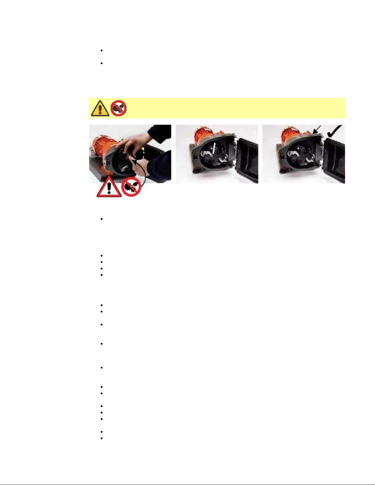
When closing the guard, check it does not make contact with the rotor. If it does, then the
rotor has been fitted incorrectly. Re-open the guard, remove and refit the rotor, and close
the guard.
Track removal (close coupled AC motor gearboxes)
Remove the rotor.
Disconnect the controlled waste pipework if attached.
Loosen the four track retaining screws using a Number 2 Pozi-Driv screwdriver.
Disconnect the mains interlock if connected to a mains contactor
Withdraw the track fully from the gearbox.
Track re-location (close coupled AC motor gearboxes)
Ensure that the track is clean.
http://www.watson-marlow.co.uk/pdfs-global/m-620r-gb-01.htm[02/02/2012 14:33:33]
Page 8

Watson-Marlow Bredel E-Manuals
Fit the track over the gearbox boss.
Align the track horizontally so that the location holes are aligned with the threaded
gearbox holes.
Tighten the four track retaining screws using a Number 2 Pozi-Driv screwdriver.
Re-connect the guard interlock controlled waste pipework if required.
620RE, 620RE4 and 620R CIP and SIP
General
Unlock the guard and disengage the rollers within the tube zone.
Close the guard and squeeze against the track until the latch clicks.
Observe a 1m safety area.
CIP
LoadSure tube elements and continuous tubing can be cleaned using CIP processes.
Ensure that the tubing material is chemically compatible with the cleaning agent that
is to be used.
If cleaning agents are spilled over the pumphead, wash down immediately.
Ensure that controlled waste pipework is fitted to allow a safe release of cleaning
agent in the event of a tube failure.
SIP
Only STA-PURE tube elements can be used in a steam in place sterilisation
processes.
STA-PURE tubing elements can be sterilised to 3A Class two and FDA minimum
recommended standard which is 121C (250F) at 1bar (14.5 psi) saturated steam for
20 minutes.
Monitor the process continuously .
If a tube failure occurs, shut down the process. Do not touch the pumphead until a
20 minute cooling period has been observed.
Ensure a 20 minute acclimatisation period is observed before running the pump
following SIP.
Ensure that controlled waste pipework is fitted to allow a safe release of steam in
the event of a tube failure.
Ensure a 1m safety zone is maintained around the pumphead during SIP cycles.
http://www.watson-marlow.co.uk/pdfs-global/m-620r-gb-01.htm[02/02/2012 14:33:33]
Page 9

Watson-Marlow Bredel E-Manuals
Ensure that the pumphead door is closed and locked before SIP
cleaning commences.
Pumphead spares
Number Spare Description
1 069.4101.000 620RTC: continuous tubing clamp set
2 MR2052C Oddie fastener
2 MR2053B Clip: Oddie retainer
2 MR2054T Oddie washer
2 SG0021 Oddie spring
2 CX0150 Oddie circlip (snap ring)
3 MRA0251A Track assembly (continuous pumphead)
3 MRA0297A Track assembly (element pumphead)
3 MR2000C Track
4 MRA0249A Roller assembly element pumphead
4 MRA0250A Roller assembly continuous pumphead
http://www.watson-marlow.co.uk/pdfs-global/m-620r-gb-01.htm[02/02/2012 14:33:33]
Page 10

Watson-Marlow Bredel E-Manuals
5 MR2027T Controlled waste threaded fitting 620R
6 MR2028M Controlled waste port blanking plug
7 MR2018T Hinge pin
8 MR2055M Rotor cover
9 MR2021B Seal - guard
10 MR2002M Guard without latch and seal
11 MR2015T Follower roller spindle
12 CX0148 Roller assembly circlip (snap-ring) E type 6 dia
12 MR2014T Stainless steel roller spindle
12 MR2010T Thrust washer
13 MR2096T Controlled waste threaded fitting locking nut
14 MRA0320A Rotor assembly 2-roller element
14 MRA0321A Rotor assembly 4-roller element
14 MRA0322A Rotor assembly 2-roller continuous
15 MR2058B Grommet - door switch
16 XX0220 Key - metal
17 MR2029T Cased drive MG605 shaft/rotor hub spacer
18 MR2059T Adaptor - Bodine (white polypropylene ring)
19 FN0488 Cased drive track locating screws M6x10
20 FN0523 Close-coupled track locating screws M6x20
21 FN0581 Rotor locating washer M6
22 FN0520 Rotor locating bolt M6 x 25
23 TT0006 5mm Allen key
24 MA0017 Magnet
MRA0268A Cased drive door switch assembly
MRA0279A Close-coupled door switch assembly
CN0187 Plug blanking 10.72M
Technical data
Performance envelope of the 620R, 620RE and 620RE4 mark II rotor
http://www.watson-marlow.co.uk/pdfs-global/m-620r-gb-01.htm[02/02/2012 14:33:33]
Page 11

Watson-Marlow Bredel E-Manuals
Flow rates
Tube bore Tube number - # rpm Pressure (+) Suction (-)
Note: Flow rates quoted have been rounded for simplicity, but are accurate to within 5% well within the normal tubing-tolerance variation of flow rate. They should therefore be
taken as a guide. Real flow rates in any application must be determined empirically.
620R
Flow rates: Marprene, Bioprene (l/min)
mm 6.4 9.6 12.7 15.9
inch 1/4 3/8 1/2 5/8
# 26 73 82 184
8-76 0.10-1.0 0.20-1.9 0.32-3.0 0.42-4.2
8-77 0.10-1.0 0.20-1.9 0.32-3.1 0.42-4.2
8-83 0.10-1.1 0.20-2.1 0.32-3.3 0.42-4.5
17-83 0.22-1.1 0.43-2.1 0.68-3.3 0.90-4.5
47-237 0.61-3.1 1.2-5.9 1.9-9.5 2.5-11
50-251 0.65-3.3 1.3-6.3 2.0-10 2.7-11
52-259 0.68-3.4 1.3-6.5 2.1-10 2.8-11
Flow rates: Marprene, Bioprene (USGPM)
mm 6.4 9.6 12.7 15.9
inch 1/4 3/8 1/2 5/8
# 26 73 82 184
8-76 0.03-0.3 0.05-0.5 0.08-0.8 0.11-1.1
8-77 0.03-0.3 0.05-0.5 0.08-0.8 0.11-1.1
8-83 0.03-0.3 0.05-0.5 0.08-0.9 0.11-1.2
17-83 0.06-0.3 0.11-0.5 0.18-0.9 0.24-1.2
47-237 0.16-0.8 0.31-1.6 0.50-2.5 0.67-2.9
50-251 0.17-0.9 0.33-1.7 0.53-2.7 0.72-3.0
52-259 0.18-0.9 0.34-1.7 0.55-2.7 0.75-3.0
Flow rates: Silicone (l/min)
mm 6.4 9.6 12.7 15.9
inch 1/4 3/8 1/2 5/8
# 26 73 82 184
8-76 0.10-0.9 0.22-2.1 0.34-3.2 0.44-4.7
8-77 0.10-0.9 0.22-2.1 0.34-3.2 0.44-4.7
8-83 0.10-1.0 0.22-2.2 0.34-3.5 0.44-5.1
17-83 0.20-1.0 0.46-2.2 0.71-3.5 0.95-5.1
47-237 0.56-2.8 1.3-6.4 2.0-10 2.8-14
50-251 0.60-3.0 1.4-6.8 2.1-11 3.0-14
http://www.watson-marlow.co.uk/pdfs-global/m-620r-gb-01.htm[02/02/2012 14:33:33]
Page 12

Watson-Marlow Bredel E-Manuals
52-259 0.62-3.1 1.4-7.0 2.2-11 3.1-15
8-77 0.30.2.8 0.47-4.5
Flow rates: Silicone (USGPM)
mm 6.4 9.6 12.7 15.9
inch 1/4 3/8 1/2 5/8
# 26 73 82 184
8-76 0.03-0.2 0.06-0.5 0.09-0.8 0.12-1.2
8-77 0.03-0.2 0.06-0.5 0.09-0.9 0.12-1.3
8-83 0.03-0.3 0.06-0.6 0.09-0.9 0.12-1.4
17-83 0.05-0.3 0.12-0.6 0.17-0.9 0.25-1.4
47-237 0.15-0.8 0.34-1.7 0.46-2.6 0.73-3.7
50-251 0.16-0.8 0.36-1.8 0.55-2.8 0.78-3.8
52-259 0.16-0.8 0.37-1.8 0.58-2.9 0.82-3.9
Flow rates: Neoprene, STA-PURE (l/min)
mm 6.4 9.6 12.7 15.9
inch 1/4 3/8 1/2 5/8
# 26 73 82 184
8-76 0.10-0.9 0.20-1.9 0.32-3.0 0.49-4.6
8-77 0.10-0.9 0.20-1.9 0.32-3.1 0.49-4.7
8-83 0.10-1.0 0.20-2.1 0.32-3.3 0.49-5.1
17-83 0.20-1.0 0.43-2.1 0.68-3.3 1.0-5.1
47-237 0.56-2.8 1.2-5.9 1.9-9.51 2.9-14
50-251 0.60-3.0 1.3-6.3 2.01-10 3.1-15
52-259 0.62-3.1 1.3-6.5 2.1-10 3.2-16
Flow rates: Neoprene, STA-PURE (USGPM)
mm 6.4 9.6 12.7 15.9
inch 1/4 3/8 1/2 5/8
# 26 73 82 184
8-76 0.03-0.2 0.05-0.5 0.08-0.8 0.13-1.2
8-77 0.03-0.2 0.05-0.5 0.08-0.8 0.13-1.2
8-83 0.03-0.3 0.05-0.5 0.08-0.9 0.13-1.3
17-83 0.05-0.3 0.11-0.5 0.18-0.9 0.27-1.3
47-237 0.15-0.8 0.31-1.6 0.50-2.5 0.76-3.8
50-251 0.16-0.8 0.33-1.7 0.53-2.7 0.81-4.0
52-259 0.16-0.8 0.34-1.7 0.55-2.7 0.84-4.2
620RE
Flow rates: Marprene TM, Bioprene TM (l/min)
mm 12 17
LoadSure LoadSure
8-76 0.30-2.8 0.47-4.5
http://www.watson-marlow.co.uk/pdfs-global/m-620r-gb-01.htm[02/02/2012 14:33:33]
Page 13

Watson-Marlow Bredel E-Manuals
8-83 0.30-3.1 0.47-4.9
17-83 0.63-3.1 1.0-4.9
47-237 1.7-8.8 2.8-14
50-251 1.9-9.3 2.9-15
52-259 1.9-9.6 3.1-15
Flow rates: Marprene TM, Bioprene TM (USGPM)
mm 12 17
LoadSure LoadSure
8-76 0.08-0.7 0.12-1.2
8-77 0.08-0.8 0.12-1.2
8-83 0.08-0.8 0.12-1.3
17-83 0.17-0.8 0.26-1.3
47-237 0.46-2.3 0.73-3.7
50-251 0.49-2.5 0.78-3.9
52-259 0.51-2.5 0.81-4.0
Flow rates: Marprene TL, Bioprene TL (l/min)
mm 12 17
LoadSure LoadSure
8-76 0.30-2.8 0.54-5.1
8-77 0.30-2.8 0.54-5.2
8-83 0.30-3.1 0.54-5.6
17-83 0.63-3.1 1.1-5.6
47-237 1.7-8.8 3.2-16
50-251 1.9-9.3 3.4-17
52-259 1.9-9.6 3.5-17
Flow rates: Marprene TL, Bioprene TL (USGPM)
mm 12 17
LoadSure LoadSure
8-76 0.08-0.7 0.14-1.4
8-77 0.08-0.8 0.14-1.4
8-83 0.08-0.8 0.14-1.5
17-83 0.17-0.8 0.30-1.5
47-237 0.46-2.3 0.84-4.2
50-251 0.49-2.5 0.89-4.5
52-259 0.51-2.5 0.92-4.6
Flow rates: Silicone (l/min)
mm 12 17
LoadSure LoadSure
http://www.watson-marlow.co.uk/pdfs-global/m-620r-gb-01.htm[02/02/2012 14:33:33]
Page 14

Watson-Marlow Bredel E-Manuals
8-76 0.31-2.9 0.49-4.6
8-77 0.31-3.0 0.49-4.7
8-83 0.31-3.2 0.49-5.16
17-83 0.66-3.2 1.0-5.1
47-237 1.8-9.2 2.9-14
50-251 1.9-9.7 3.0-15
52-259 2.0-10 3.2-16
Flow rates: Silicone (USGPM)
mm 12 17
8-76 0.08-0.8 0.13-1.2
8-77 0.08-0.8 0.13-1.2
8-83 0.08-0.8 0.13-1.3
17-83 0.17-0.8 0.27-1.3
47-237 0.48-2.4 0.76-3.8
LoadSure LoadSure
50-251 0.51-2.6 0.80-4.0
52-259 0.53-2.6 0.84-4.2
Flow rates: Neoprene, STA-PURE (l/min)
mm 12 17
LoadSure LoadSure
8-76 0.32-3.0 0.58-5.5
8-77 0.32-3.1 0.58-5.6
8-83 0.32-3.3 0.58-6.0
17-83 0.68-3.3 1.2-6.0
47-237 1.9-9.4 3.4-17
50-251 2.0-10 3.6-18
52-259 2.1-10 3.8-19
Flow rates: Neoprene, STA-PURE (USGPM)
mm 12 17
LoadSure LoadSure
8-76 0.08-0.8 0.15-1.4
8-77 0.08-0.8 0.15-1.5
8-83 0.08-0.9 0.15-1.6
17-83 0.18-0.9 0.32-1.6
47-237 0.49-2.5 0.90-4.5
50-251 0.53-2.6 0.95-4.8
52-259 0.55-2.7 0.99-4.9
620RE4
Flow rates: Marprene TM, Bioprene TM (l/min)
http://www.watson-marlow.co.uk/pdfs-global/m-620r-gb-01.htm[02/02/2012 14:33:33]
Page 15

Watson-Marlow Bredel E-Manuals
mm 12 17
LoadSure LoadSure
8-76 0.25-2.4 0.33-3.1
8-77 0.25-2.4 0.33-3.2
8-83 0.25-2.6 0.33-3.4
17-83 0.54-2.6 0.70-3.4
47-237 1.5-7.5 1.9-9.8
50-251 1.6-7.9 2.1-10
52-259 1.6-8.2 2.1-11
Flow rates: Marprene TM, Bioprene TM (USGPM)
mm 12 17
LoadSure LoadSure
8-76 0.07-0.6 0.09-0.8
8-77 0.07-0.6 0.09-0.8
8-83 0.07-0.7 0.09-0.9
17-83 0.14-0.7 0.19-0.9
47-237 0.39-2.0 0.51-2.6
50-251 0.42-2.1 0.54-2.7
52-259 0.43-2.2 0.57-2.8
Flow rates: Marprene TL, Bioprene TL (l/min)
mm 12 17
LoadSure LoadSure
8-76 0.25-2.4 0.38-3.6
8-77 0.25-2.4 0.38-3.6
8-83 0.25-2.6 0.38-3.9
17-83 0.54-2.6 0.80-3.9
47-237 1.5-7.5 2.2-11
50-251 1.6-7.9 2.4-12
52-259 1.6-8.2 2.4-12
Flow rates: Marprene TL, Bioprene TL (USGPM)
mm 12 17
LoadSure LoadSure
8-76 0.07-0.6 0.10-0.9
8-77 0.07-0.6 0.10-1.0
8-83 0.07-0.7 0.10-1.0
17-83 0.14-0.7 0.21-1.0
47-237 0.39-2.0 0.58-2.9
50-251 0.42-2.1 0.62-3.1
52-259 0.43-2.2 0.65-3.2
http://www.watson-marlow.co.uk/pdfs-global/m-620r-gb-01.htm[02/02/2012 14:33:33]
Page 16

Watson-Marlow Bredel E-Manuals
Flow rates: Silicone (l/min)
mm 12 17
LoadSure LoadSure
8-76 0.26-2.5 0.34-3.2
8-77 0.26-2.5 0.34-3.3
8-83 0.26-2.7 0.34-3.5
17-83 0.56-2.7 0.72-3.5
47-237 1.5-7.8 2.0-10
50-251 1.6-8.3 2.1-11
52-259 1.7-8.5 2.2-11
Flow rates: Silicone (USGPM)
mm 12 17
LoadSure LoadSure
8-76 0.07-0.7 0.09-0.9
8-77 0.07-0.7 0.09-0.9
8-83 0.07-0.7 0.09-0.9
17-83 0.15-0.7 0.19-0.9
47-237 0.41-2.1 0.53-2.7
50-251 0.43-2.2 0.56-2.8
52-259 0.45-2.3 0.59-2.9
Flow rates: Neoprene, STA-PURE (l/min)
mm 12 17
LoadSure LoadSure
8-76 0.27-2.6 0.40-3.8
8-77 0.27-2.6 0.40-3.9
8-83 0.27-2.8 0.40-4.2
17-83 0.57-2.8 0.86-4.2
47-237 1.6-8.0 2.4-12
50-251 1.7-8.5 2.5-13
52-259 1.8-8.8 2.6-13
Flow rates: Neoprene, STA-PURE (USGPM)
mm 12 17
LoadSure LoadSure
8-76 0.07-0.7 0.11-1.0
8-77 0.07-0.7 0.11-1.0
8-83 0.07-0.7 0.11-1.1
17-83 0.15-0.7 0.23-1.1
47-237 0.42-2.1 0.63-3.2
50-251 0.45-2.2 0.67-3.3
http://www.watson-marlow.co.uk/pdfs-global/m-620r-gb-01.htm[02/02/2012 14:33:33]
Page 17

Watson-Marlow Bredel E-Manuals
52-259 0.46-2.3 0.69-3.5
620R product codes
mm inch # Marprene Bioprene
6.4 1/4 26 902.0064.032 903.0064.032 910.0064.032 913.0064.032
9.6 3/8 73 902.0096.032 903.0096.032 910.0096.032 913.0096.032
12.7 1/2 82 902.0127.032 903.0127.032 910.0127.032 913.0127.032
15.9 5/8 184 902.0159.032 903.0159.032 910.0159.032 913.0159.032
mm inch # STA-PURE Neoprene Butyl Tygon
6.4 1/4 26 960.0064.032 920.0064.032 930.0064.032 950.0064.032
9.6 3/8 73 960.0096.032 920.0096.032 930.0096.032 950.0096.032
12.7 1/2 82 960.0127.032 920.0127.032 930.0127.032 950.0127.032
15.9 5/8 184 960.0159.032 920.0159.032 930.0159.032 950.0159.032
Gore
mm inch # Fluorel
6.4 1/4 26 970.0064.032 965.0064.032
9.6 3/8 73 970.0096.032 965.0096.032
fluoroelastomer
/PTFE
Peroxide
silicone
Platinum
silicone
12.7 1/2 82 970.0127.032 965.0127.032
15.9 5/8 184 970.0159.032 965.0159.032
620RE and 620RE4 LoadSure product codes
12mm
DIN 15
STA-PURE 960.0120.PFD 960.0120.PFT 960.0170.PFD 960.0170.PFT
Gore
fluoroelastomer
/PTFE
Bioprene TM 903.M120.PFD 903.M120.PFT 903.M170.PFD 903.M170.PFT
Bioprene 903.0120.PFD 903.0120.PFT 903.0170.PFD 903.0170.PFT
Platinum
silicone
Marprene TM 902.M120.PPC 902.M170.PPC
Marprene 902.0120.PPC 902.0170.PPC
965.0120.PFD 965.0120.PFT 965.0170.PFD 965.0170.PFT
913.0120.PFD 913.0120.PFT 913.0170.PFD 913.0170.PFT
12mm
Cam and Groove
3/4in
12mm
Tri-clamp 3/4in
17mm
Cam and Groove
3/4in
17mm
DIN 15
17mm
Tri-clamp
3/4in
Peroxide
silicone
Neoprene 920.0120.PPC 920.0170.PPC
Trademarks and disclaimer
Watson-Marlow, Loadsure, Bioprene and Marprene are trademarks of Watson-Marlow
http://www.watson-marlow.co.uk/pdfs-global/m-620r-gb-01.htm[02/02/2012 14:33:33]
910.0120.PPC 910.0170.PPC
Page 18

Watson-Marlow Bredel E-Manuals
Limited.
TYGON is a trademark of the Saint Gobain Performance Plastics Company.
STA-PURE is a trademark of W L Gore & Associates.
The information contained in this document is believed to be correct but Watson-Marlow
Limited accepts no liability for any errors it contains, and reserves the right to alter
specifications without notice.
Patient-connected use: warning
Warning: These products are not designed for use in, and should not be used for patient
connected applications.
Publication history
m-620r-gb-01.htm: Watson-Marlow 620R
First published 11 02.
Decontamination certificate
In compliance with the UK Health and Safety at Work Act and the Control of Substances
Hazardous to Health Regulations, you are required to declare the substances which have
been in contact with product(s) you return to Watson-Marlow or its subsidiaries or
distributors. Failure to do so will cause delays. Please ensure that you fax us this form and
receive an RGA (Returned Goods Authorisation) before you despatch the product(s). A
copy of this form must be attached to the outside of the packaging containing the
product(s). Please complete a separate decontamination certificate for each product.
Your name Company
Address
Postcode/zip Country
Telephone Fax
Product type Serial number
To speed the repair, please
describe all known faults
The product has ...
Names of chemicals
handled with product(s)
You are responsible for cleaning and decontaminating the product(s) before return.
Been used Not been used
If the product has been used, please complete all the following sections. If the product has
not been used, please just sign this form.
Precautions to be taken in
handling these chemicals
Action to be taken in the
event of human contact
I understand that the personal data collected will be kept confidentially in accordance with
the UK Data Protection Act 1998.
http://www.watson-marlow.co.uk/pdfs-global/m-620r-gb-01.htm[02/02/2012 14:33:33]
Page 19

Watson-Marlow Bredel E-Manuals
RGA number
Signature
Your position
Date
Please print out, sign and fax to Watson-Marlow Pumps at +44 1326 376009.
http://www.watson-marlow.co.uk/pdfs-global/m-620r-gb-01.htm[02/02/2012 14:33:33]
 Loading...