

Page 1
Service.
Self-Study Programme 270
The Phaeton
Page 2
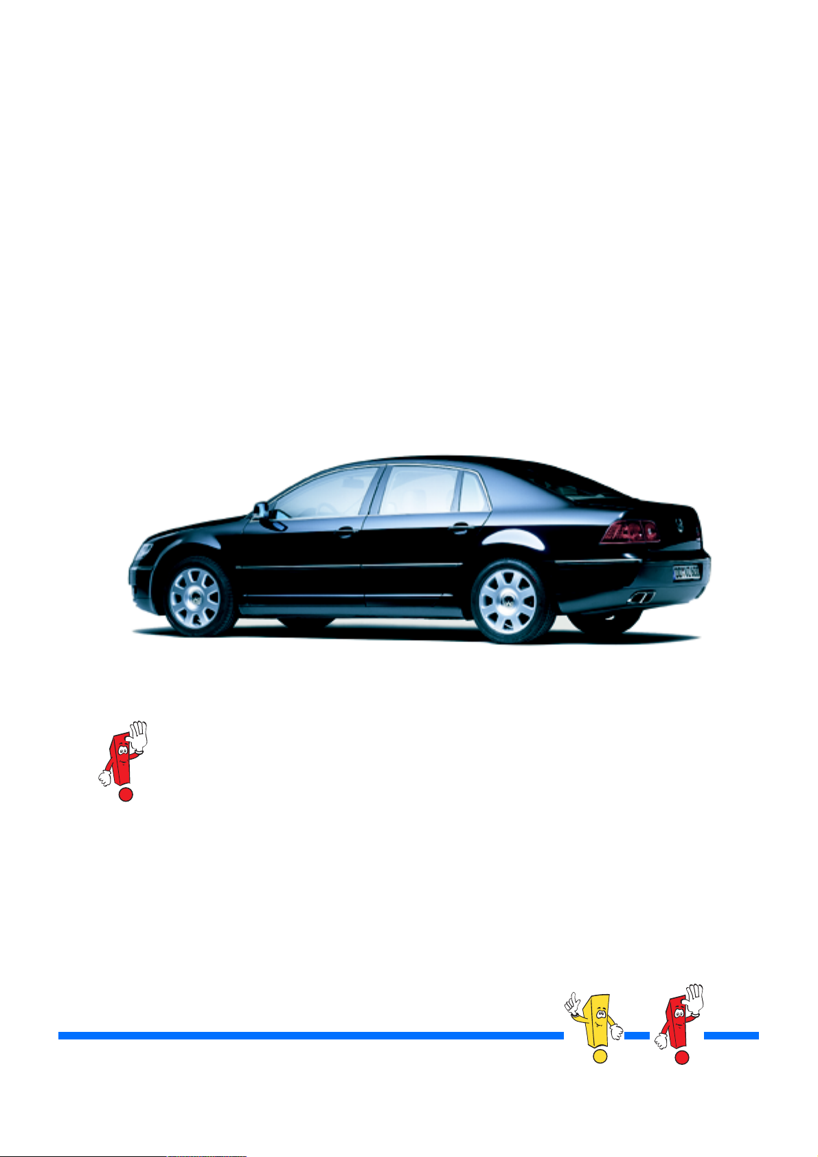
The Phaeton — Volkswagen's flagship — is
based on developments in the international market for luxury goods: a product's quality alone is
no longer sufficient to guarantee success in
highly-developed markets. The prestige and
value of the brand are decisive in influencing
purchase decision-making.
Customers' brand awareness is becoming
increasingly manifest, thereby necessitating
Volkswagen's entry into the higher-class segment.
The launch of the Phaeton witnesses the development of a product which meets customers' technical requirements as well as satisfying the value
and prestige demands made on the Volkswagen
brand.
There are separate self-study programmes on the following topics:
W-engines (SSP248/250),
Air-conditioning/Heating (SSP271),
On-board network (SSP272),
Convenience and safety electronics (SSP273),
Infotainment (SSP274),
Air suspension (SSP275),
Automatic distance control ADC (SSP276),
Chassis (SSP277).
The self-study programme illustrates the structure
and operation of new developments!
Contents will not be updated.
2
270_241
NEW Caution
Note
Please refer to the appropriate service material for current
test, setting and repair instructions.
Page 3

At a Glance
In a nutshell . . . . . . . . . . . . . . . . . . . . . . . . . . . . . . . . . . .4
Bodywork . . . . . . . . . . . . . . . . . . . . . . . . . . . . . . . . . . . 12
Passenger protection. . . . . . . . . . . . . . . . . . . . . . . . . . .26
Engines. . . . . . . . . . . . . . . . . . . . . . . . . . . . . . . . . . . . . .32
Gearbox . . . . . . . . . . . . . . . . . . . . . . . . . . . . . . . . . . . . .38
Chassis . . . . . . . . . . . . . . . . . . . . . . . . . . . . . . . . . . . . . .50
Convenience electronics . . . . . . . . . . . . . . . . . . . . . . . .52
Electrics . . . . . . . . . . . . . . . . . . . . . . . . . . . . . . . . . . . . .56
Heating/air-conditioning system . . . . . . . . . . . . . . . . .66
Infotainment . . . . . . . . . . . . . . . . . . . . . . . . . . . . . . . . .70
Service . . . . . . . . . . . . . . . . . . . . . . . . . . . . . . . . . . . . . . 74
3
Page 4
In a nutshell
The Phaeton name
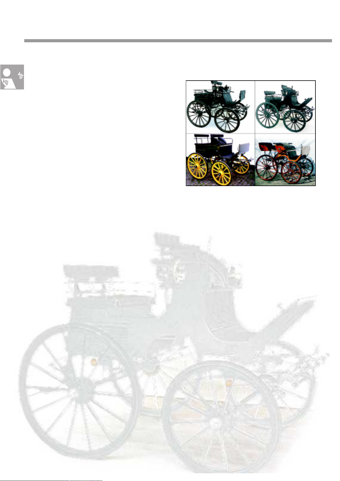
The Phaeton or Phaethon name is originally
derived from Greek mythology. Phaeton (the
'incandescent') was the son of the sun god
Helios, who was the owner of the sun chariot.
Derived from this, Phaetons also refer to the
four-wheeled walking coaches which have been
popular since the 18th century. This refers to open
owner-driver carriages, featuring a trestle seat
for 2 persons with or without a canopy top.
Behind the trestle seat there is a seat for one or
two passengers facing forwards.
Even nowadays, these Phaetons are driven at
special tournaments - original specimens having
become extremely coveted collector items.
At the onset of the 20th century, the term
Phaeton stood for touring carriages with a fabric
canopy and without side windows.
The name’s phonetics*
Phaeton - How’s it pronounced?
Phaeton is pronounced as follows:
Fay - ton.
270_150
The ending is spoken with an unvoiced 'N', comparable with the pronunciation of the word Futon, Fla-
con or Anton.
*Phonology
270_151
4
4
Page 5
Phaeton’s place in
automotive history
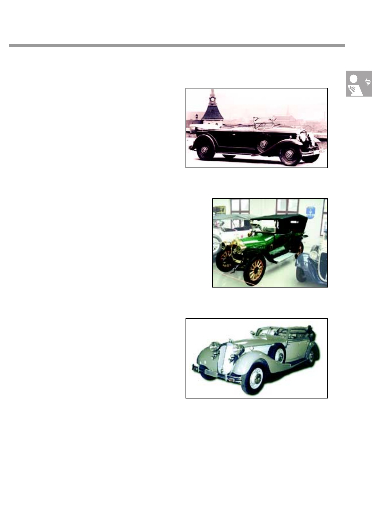
Since 1910, August Horch endowed some of
his models with the “Phaeton” suffix.
The Horch 18/90 bhp 450 Phaeton 1931, the
Horch 12/28 bhp Phaeton 1911 as well as the
Horch 853A Parade Phaeton with only three
specimens dating from 1937, the last remaining model of which is being traded at
US$ 334,000, are just a few examples.
The fact that Volkswagen has chosen the
name Phaeton for the group's flagship is an
indication of the continuation of a tradition of
making superior quality-control requirements
in the production phase, thus providing the
ultimate in exclusivity for each future owner of
a Phaeton.
270_169
Horch 18/90 bhp 450 Phaeton, 1931-32
Horch 12/28 bhp Phaeton, 1910-11
Horch 853A Parade Phaeton, 1937
270_170
270_168
5
Page 6
In a nutshell
The concept
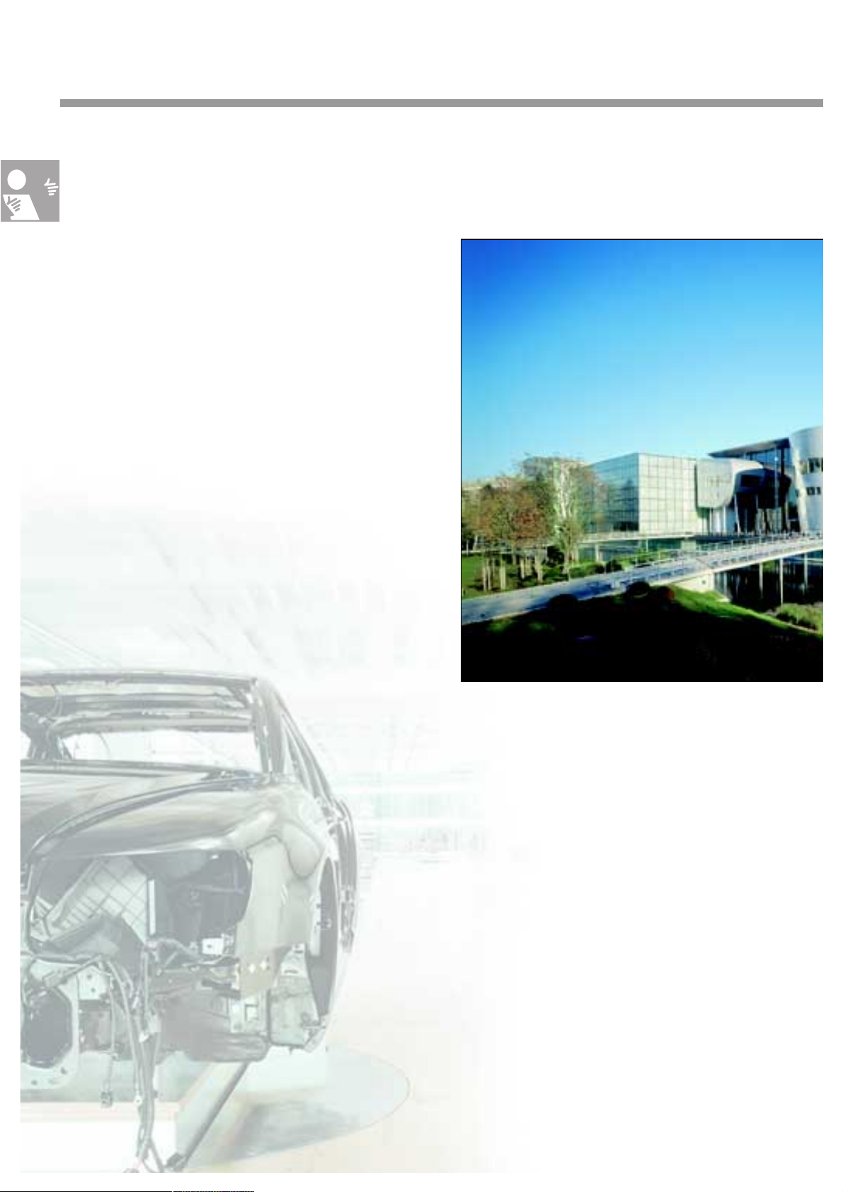
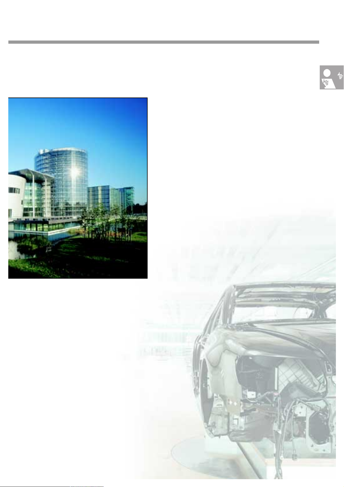
The transparent factory represents a further
significant milestone for Volkswagen's customer-oriented manufacturing and delivery.
Not only has the exclusive Phaeton led to the
building of an impressive production line in
Dresden, but it has also engendered the
inception of a polished and precisely-functioning logistics concept. In addition to these
outstanding technical production details, purchasers of this high-grade automobile can
expect a perfectly-arranged vehicle transfer
corresponding to an event of superlative
pomp.
The Transparent
270_128
The production
Contrary to the popular opinion that automobile
manufacture is irrevocably linked with dirt and oil,
the vision of manufacturing evident in Dresden
depicts production in an almost noble light. The core
element of the manufacturing process features overlapping conveyor belts with fine wood parquet
instead of metal lines. This high-grade optical characteristic in the production line is reminiscent of a
manufacturing atmosphere otherwise witnessed
only in elite luxury sports car forges.
6
6
Page 7
Factory
The logistics
An automated system steers the baskets containing the vehicles' individual components
through the factory. The basket 'accompanies'
the corresponding vehicle throughout the
assembly stage. This avoids unnecessary journeys. The chassis, including the engine, gearbox and exhaust system, as well as the body
are simultaneously mounted on different
floors, being transported to a different level in
a glass elevator, before being finally assembled into the complete vehicle. Once the manufacturing process has been completed, the
Phaeton is once again placed on the overlapping conveyor belt before receiving its finishing touches and its final check.
270_130
The event*
An exclusive automobile cries out for the
appropriate stage-management of its delivery. Customers are the centre of attention in
the transparent factory's emotionally and
technologically impressive discovery area.
Potential Phaeton owners are treated to a
birds-eye view of production via livecam during a Virtual Production Tour.
*happening, show
7
7
Page 8
In a nutshell
The Phaeton
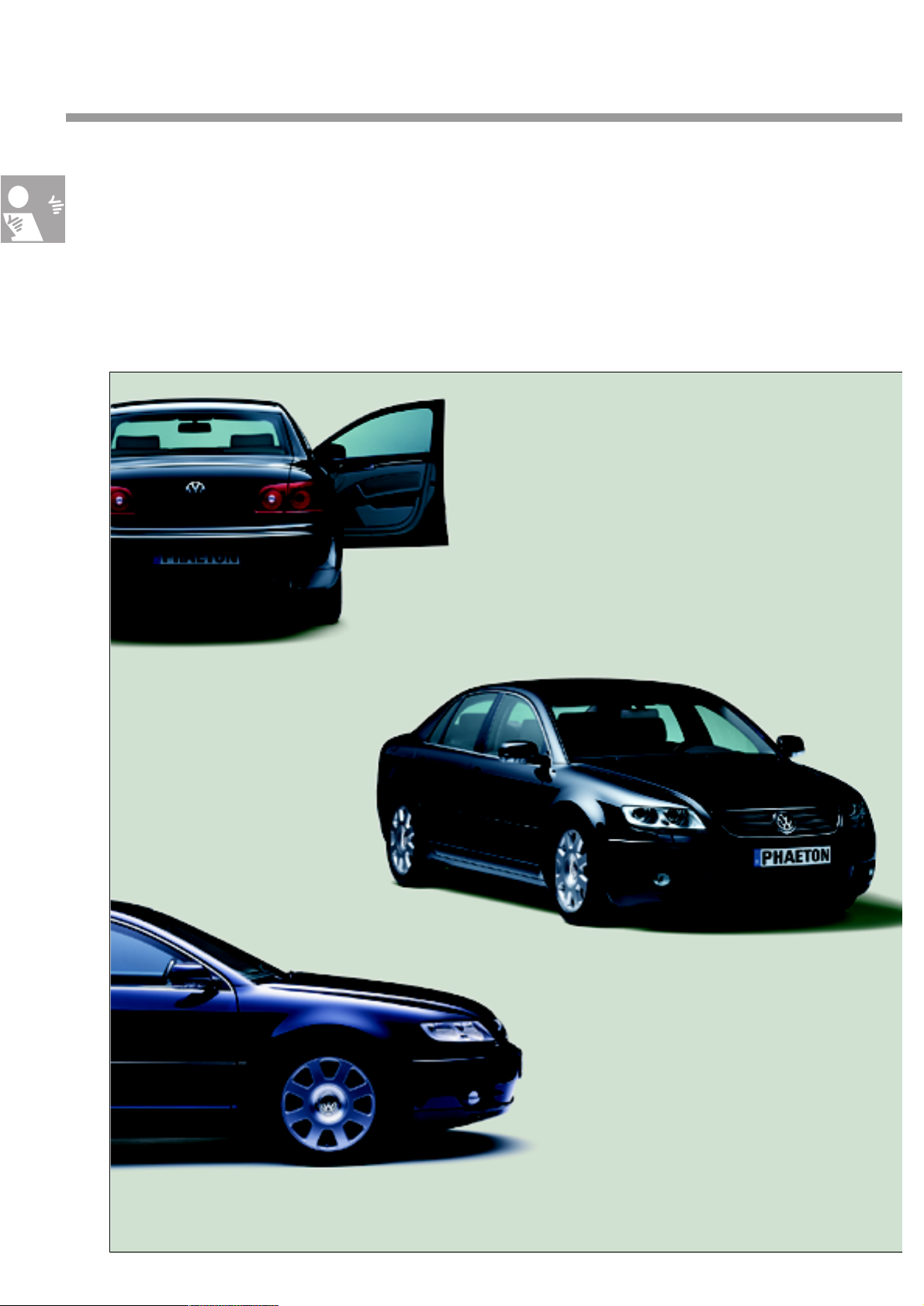
This two-page spread affords an overview of technical innovations. Detailed descriptions of the individual topics can be found in this and other Phaeton self-study programmes.
Phaeton innovations
● Rear window heated by practically invisible
tungsten threads
● Mudguards and spare tyre recess made of plastic
● Fully-galvanised body
● Tail lights with
2-colour LED technology
● Antennae invisibly
integrated in the rear window
● Extremely narrow body jointing, PVC-free
underbody protection
● Doors, engine bonnet and tailgate
made of aluminium
● Superior paintwork, anti-scratch,
exceptional brilliancy
● Air-conditioned 12- and
18-position seats, keyless access
function, automatic distance control,
multifunctional steering wheel
270_053
● Infotainment system with navigation, TV and radio/CD, CD changer in the glove
compartment, 4-zone air-conditioning, solar roof
8
Page 9
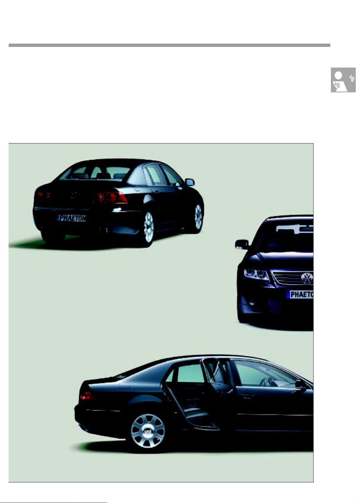
● Surrounding illumination via front, rear and forward lighting
simplifies orientation when getting out of the car in the dark
● 4-corner air suspension with automatic control
● Electro-mechanical high-pressure nozzles for cleaning headlights
● Xenon headlights with
automatic headlight range
control
● Heated, heat-insulating and infrared-reflecting windscreen
● Side and rear windows made of twin-pane laminated safety glass
270_054
9
Page 10
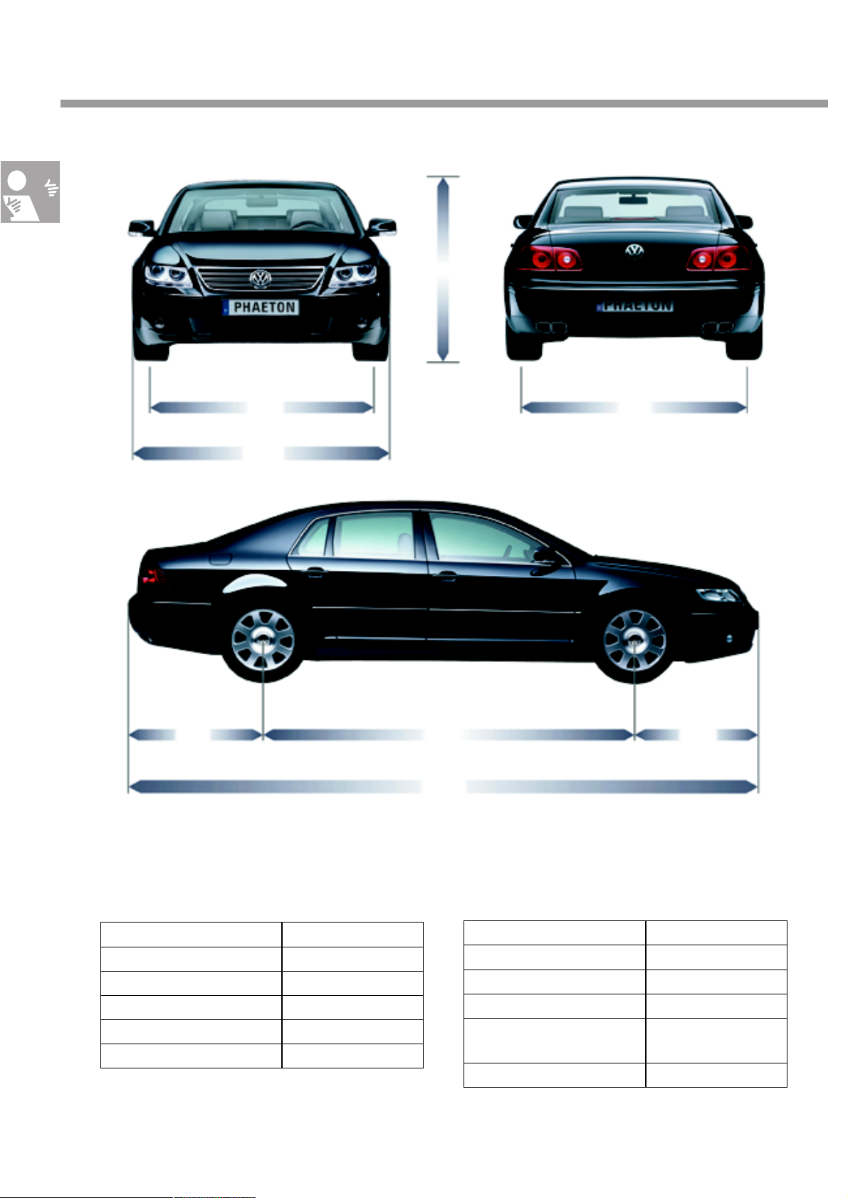
Technical data
1450
1628
1903
1612
2881 10511121
5055
270_118
10
Dimensions and weights
Length 5,055 mm
Width 1,903 mm
Height 1,450 mm
Wheelbase 2,881 mm
Turning circle 12 m
Ta nk vo lu me 9 0 l
Front track width 1,628 mm
Rear track width 1,612 mm
Total permitted weight 2,600 - 2,990 kg*
Empty weight 1,995 -2,413 kg*
Luggage compartment
space
Drag coefficient 0.32 c
500 l
w
*depending on the engine
Page 11
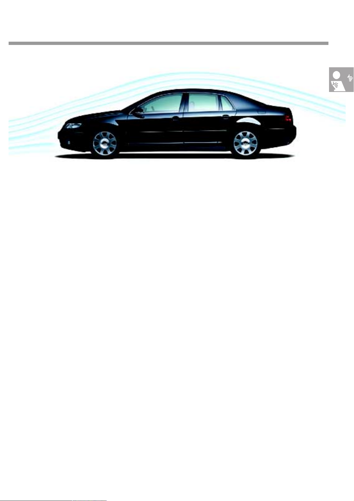
Aerodynamics
270_047
The aerodynamics
The Phaeton has a low drag coefficient of 0.32 cw — a level which was achieved by applying various
measures:
● The underbody has an extremely smooth design,
● The windscreen wipers are embedded,
● The body gap dimensions are very low,
● The front has an arrow-shaped design and
● The body is lowered at higher speeds.
Small features such as the retractable headlight cleaning nozzles, the antenna-free body and the smooth
body transitions are also responsible for this low drag coefficient.
11
Page 12
Bodywork
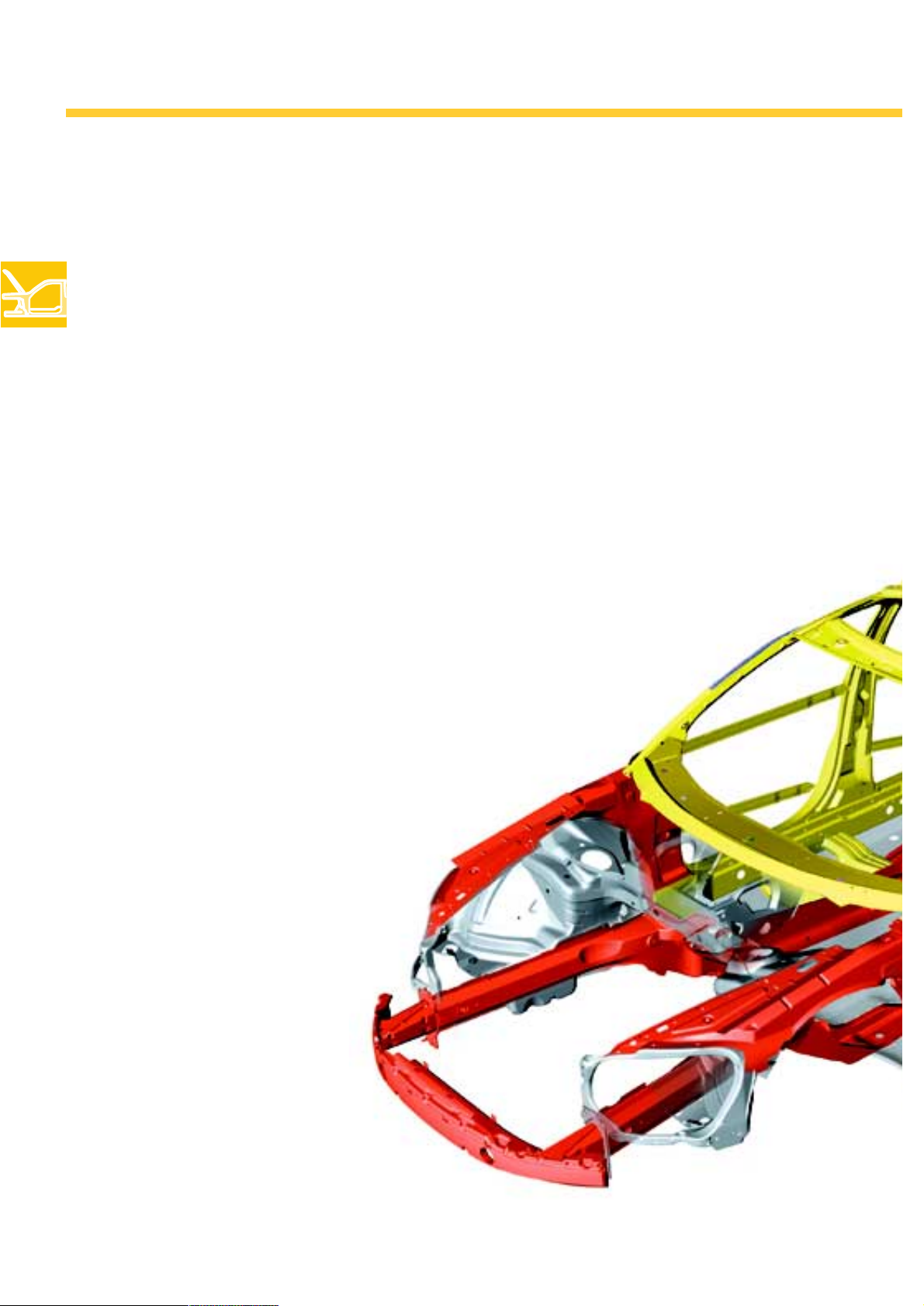
The raw bodywork of the Phaeton
The body structure
The Phaeton's bodywork is a complete innovation.
The core design focus involved a high level of
crash safety and body rigidity. The gap dimensions of the flaps and doors prove to be very low
due to the high body rigidity.
Static rigidity
The extremely high static rigidity is a
prerequisite for:
- optimal chassis design
due to almost complete lack of inherent
movement within the bodywork and
- excellent door and flap functioning
with the tightest of gap dimensions.
Doors and flaps are made of aluminium and the
front mudguards are made of plastic in order to
limit the weight while still observing the high
safety and comfort requirements.
Furthermore, the bodywork consists of highgrade and super high-strength steels and is completely galvanised.
12
270_154
Page 13
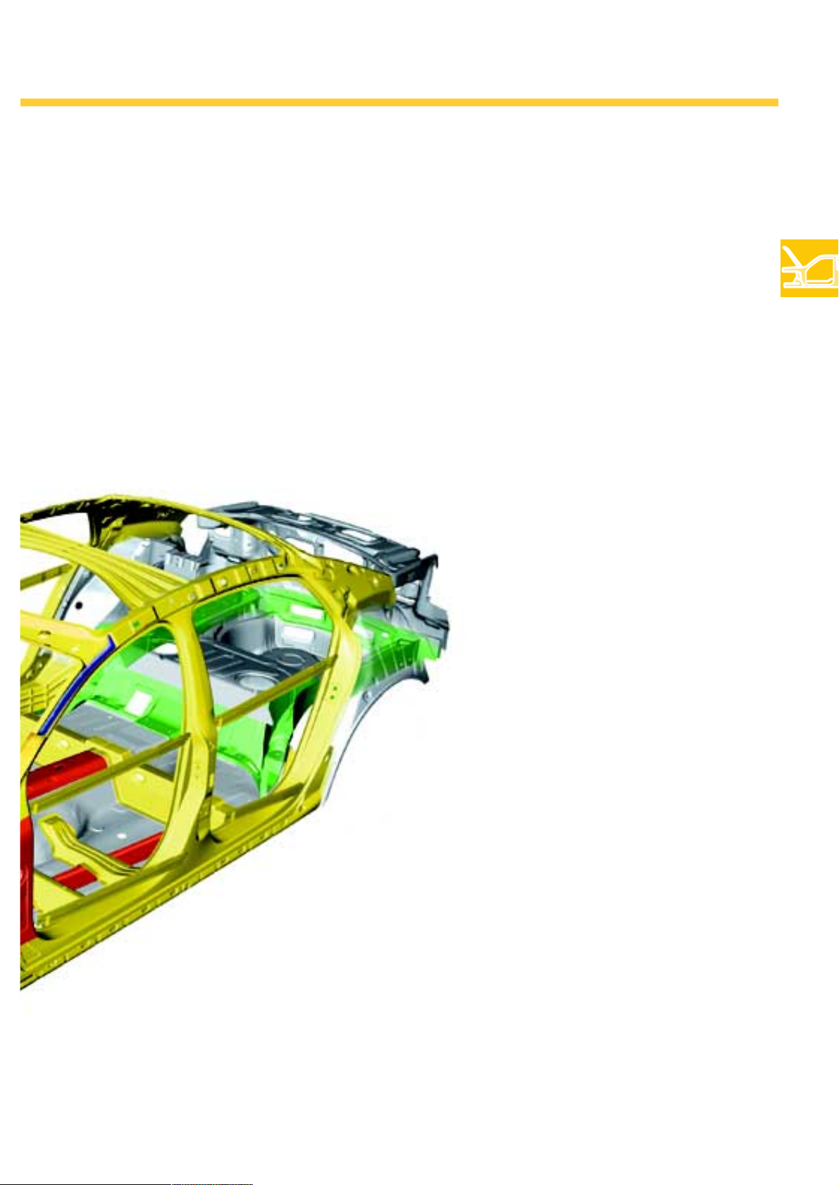
Safety features of the raw bodywork
● High energy absorption at the front and
rear of the vehicle
● Stable passenger compartment
● High protection in event of side impact
due to the:
- bonding of the B-pillar made of super
high-strength steel with the side member,
- high-strength aluminium profiles in
the doors
● Partner protection: Due to the relatively soft
external bodywork areas, the crash
performance is designed to afford maximum
protection to other parties involved in
an accident.
● Use of high-grade and super
high-strength steel
in important areas
Dynamic rigidity
The high dynamic rigidity is a
prerequisite for:
- advantageous vibration
characteristics and thus for a high
level of comfort and
- acoustic comfort
(no noises caused by movement of
270_155
the interior panelling).
Key:
red = main frontal crash area
yellow = passenger compartment
green = main rear crash area
dark blue = epoxy resin foam
light blue = plastic reinforcement
13
Page 14
Bodywork
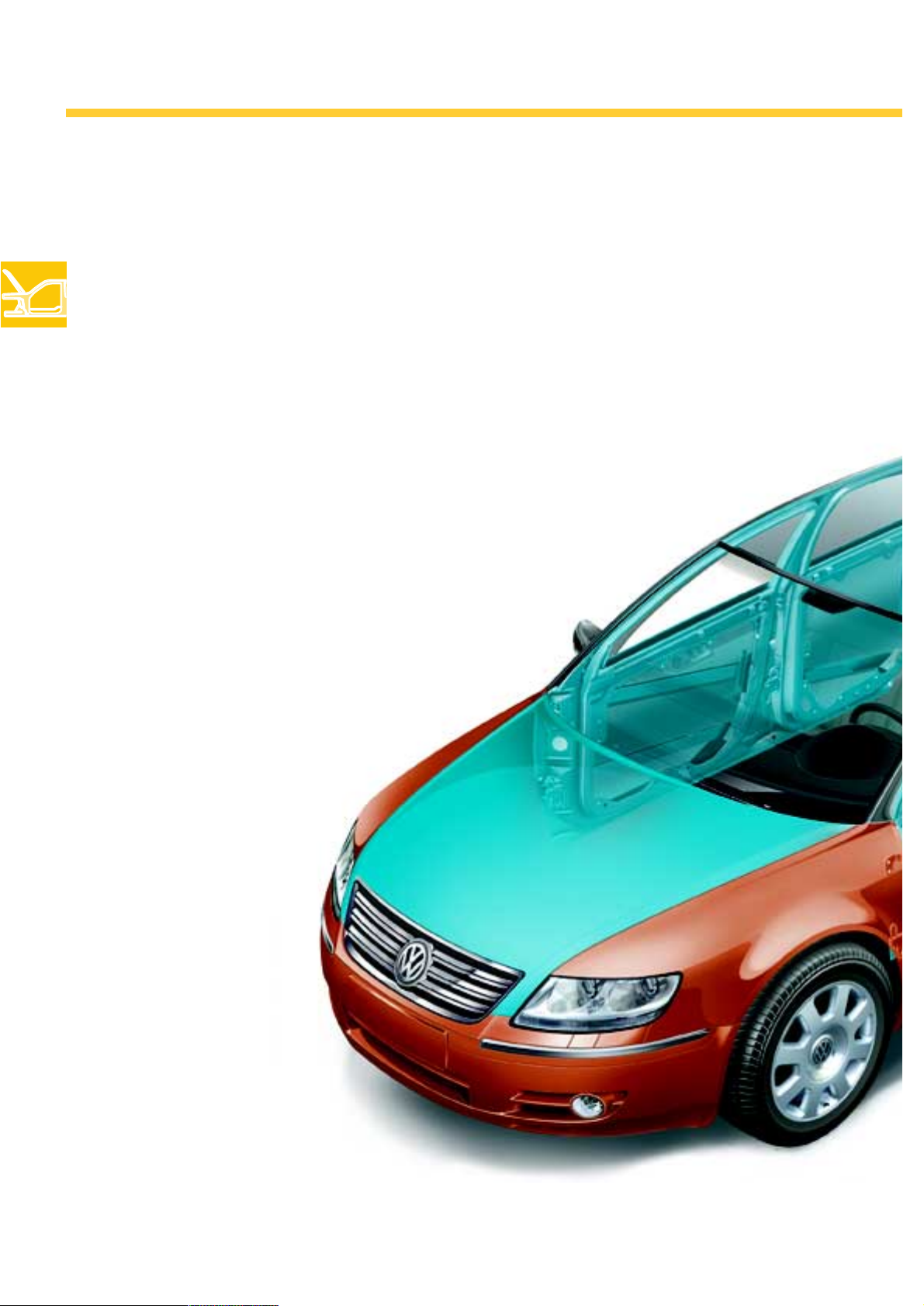
Bodywork attachments
Aluminium parts
● Engine bonnet
● Reinforced doors
● Ta il g at e
Plastic parts
● Front mudguard
● Fuel cap
● Spare tyre recess
● Front and rear bumpers
14
Key:
blue = aluminium parts
brown = plastic
270_114
Page 15
Glued-in-place plastic spare tyre recess
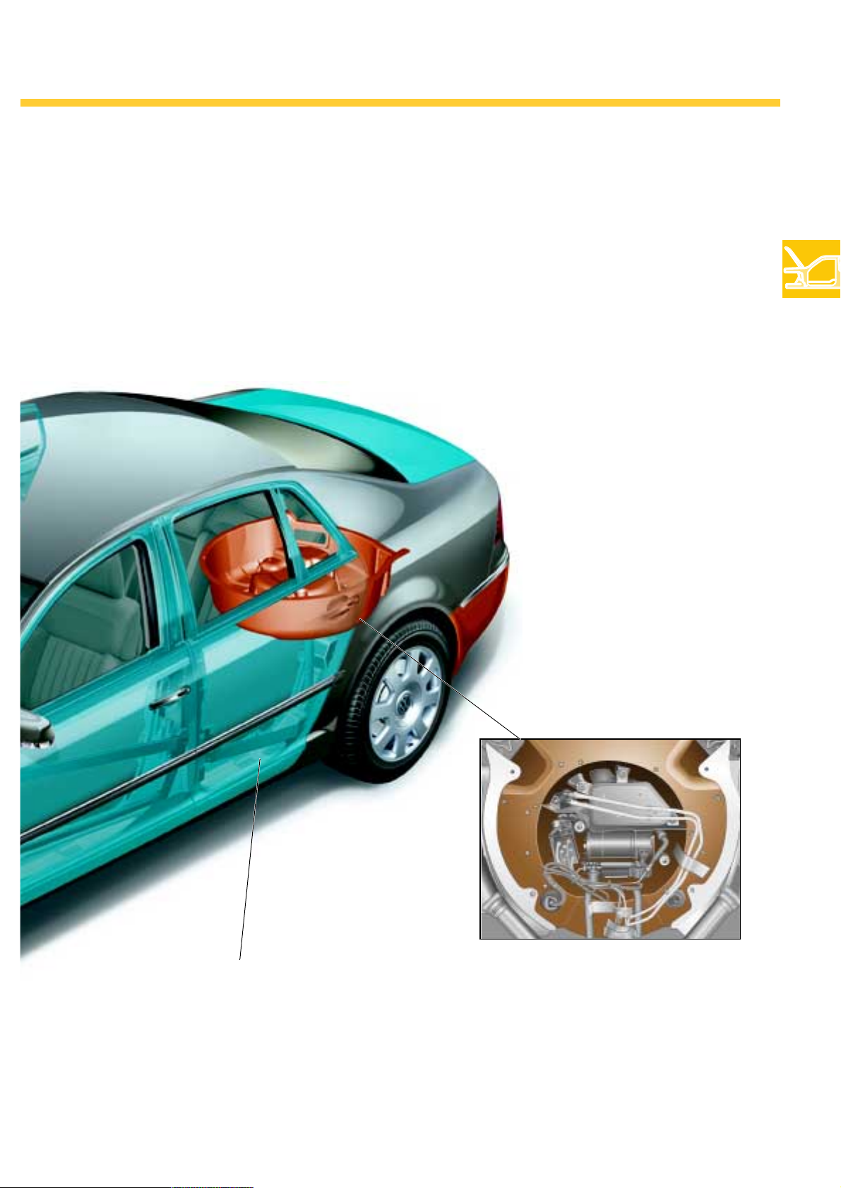
The following components are integrated in the spare tyre recess:
- Compressor for air suspension,
- Activated carbon filter and
- Spare wheel.
Doors with high-strength inner sections made
of die casting, laser-welded
270_115
270_004
Detailed view of spare tyre cavity, from below
15
Page 16
Bodywork
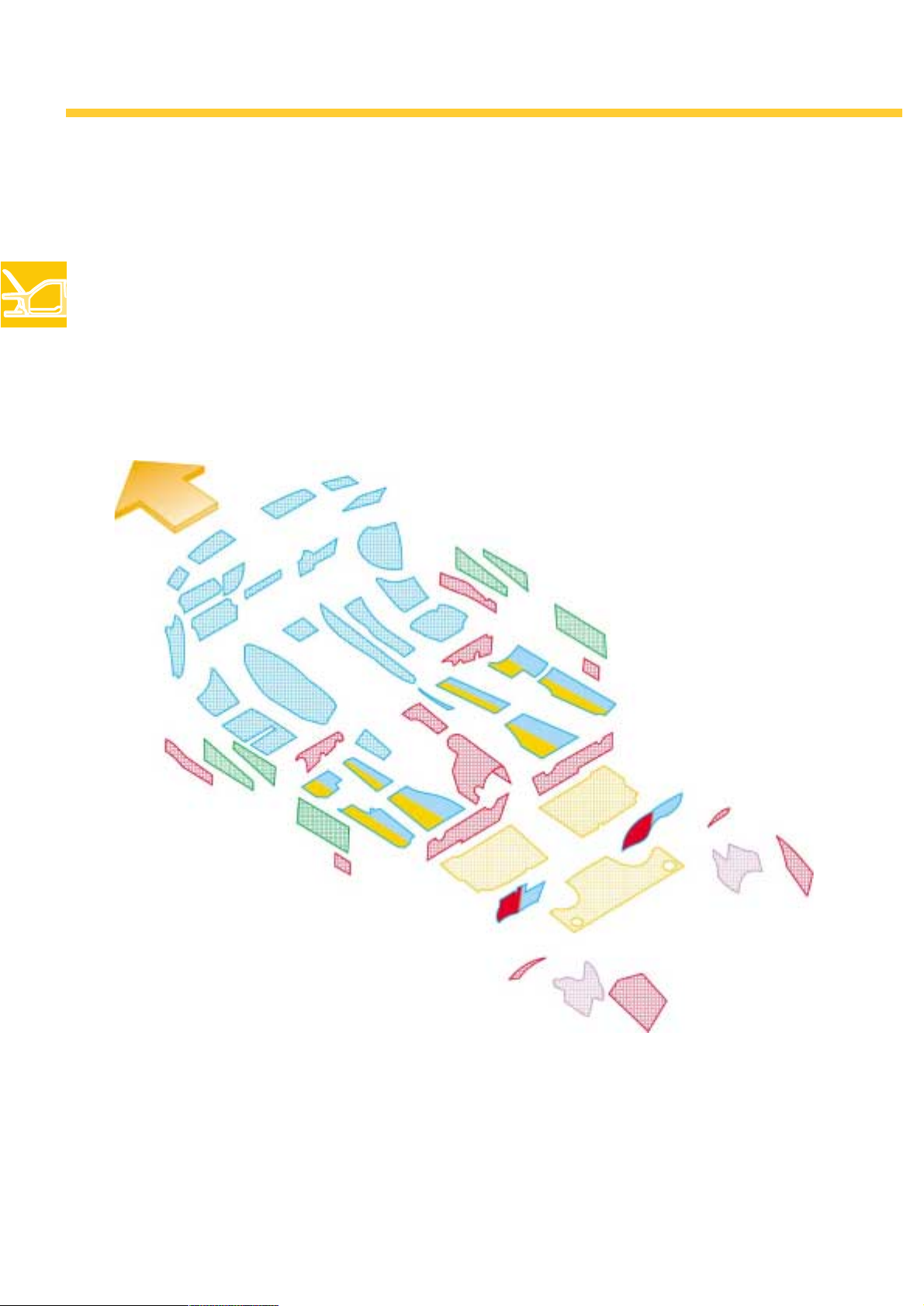
The silencers
Sound deadening was already a major issue when developing the body-in-white. The consistent deployment of absorption materials in the engine compartment, tunnel, luggage compartment and behind the
panelling has led to the attainment of an above-average reduction in noise.
Diesel and petrol engine
The two-tone insulating foils demonstrate the different insulation methods in the diesel and petrol engine.
16
270_182
Key:
blue = aluminium expansion foil, 4.5 mm sandwich
green = bitumen plastic-foil, pressure-sensitive bonding, 2 mm
red = bitumen plastic-foil, magnetised, thermoplastic bonding 2 mm
orange = bitumen plastic-foil, thermoplastic bonding 2 mm
pink = bitumen foil with aluminium foil, magnetised, 3 mm
blue/red = blue - diesel, red - petrol engine
blue/orange = blue - diesel, orange - petrol engine
Page 17
High-insulation glazing & laminated glass
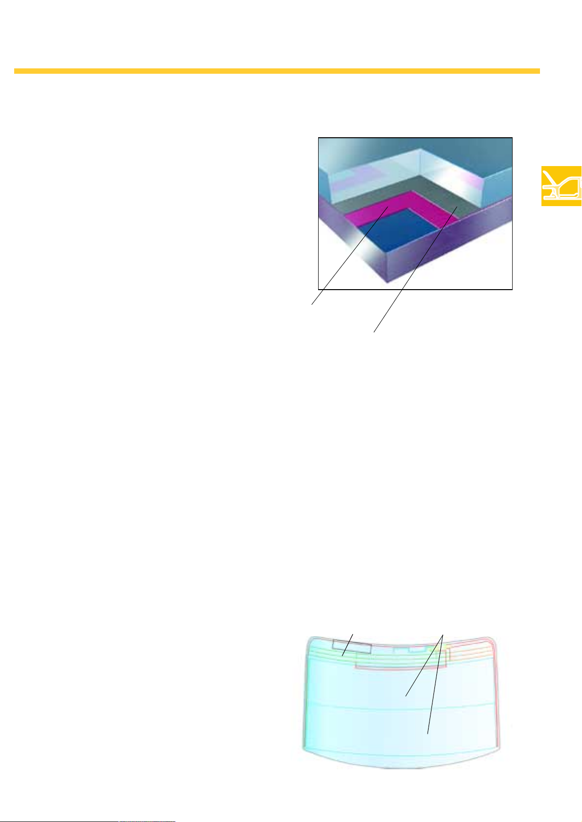
The high-insulation glazing made of laminated
glass distinguishes itself with its improved reduction of thermal exposure, however, without influencing permeability to light.
The glazing reduces ultraviolet radiation and
contributes to an improved noise insulation. This
is facilitated by two foils incorporated into the
glazing. The rear and side windows are also
manufactured with thermally-tempered laminated glass with an infrared reflective coating.
This improves safety as laminated glass panes
cannot shatter due to their incorporated safety
foils.
270_040
Ultraviolet protective foil
Infrared reflective coating
(heated windscreen)
Windscreen
● Two-layer, burglar-inhibiting,
heat-insulating, laminated safety glass
● Electric windscreen heating
(optional) with invisible filaments
through an electrically conductive
infrared reflective coating.
● The heated windscreen is switched on and off
using the 'Defrost' button at the
display and operating unit at the front
Rear window with tungsten threads
The rear window is heated by practically invisible
tungsten threads which are embedded between
the inner and outer pane. Furthermore, all antennae are integrated in the upper third of the rear
window. The external streamlined quality is therefore not impeded by bothersome antennae.
Heating duration depending on
outside temperature:
5 to 0 °C = 2 minutes
-20 °C = 4 minutes
-40 °C = 6 minutes
In order not to overload the on-board network,
the heating is switched off after a specific timeframe, depending on the outside temperature.
Antennae Heated sections
270_178
17
Page 18
Bodywork
The tailgate
Power-assisted closing of the tailgate
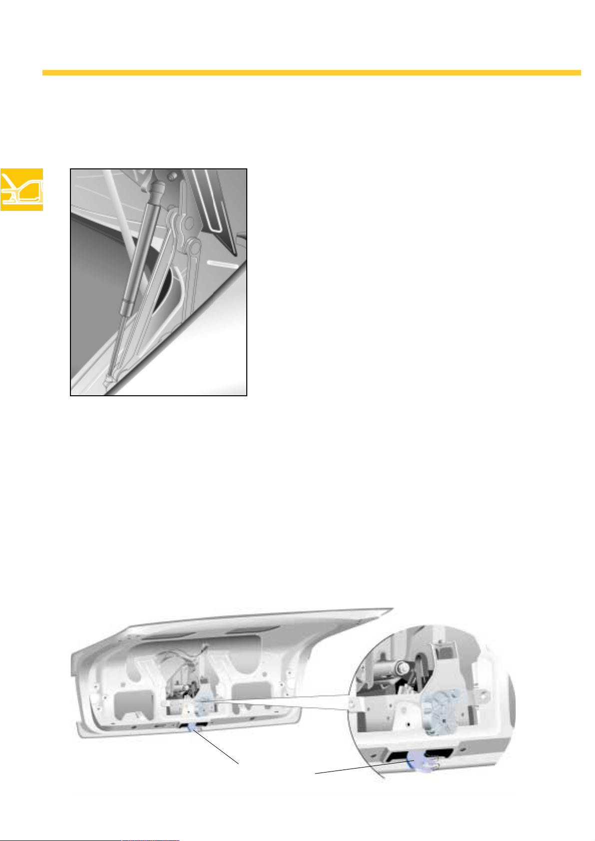
The Phaeton is also available with a system allowing the
driver to automatically open and close the tailgate.
This power-assisted closure is not only a comfort feature
but is also an enhancement of the entire locking mechanism.
270_001
Retractable rear lock with closing aid
The lock is retracted when opening the tailgate,
thereby eliminating the risk of injury. The retraction of the lock also prevents the possible soiling
of clothing by the oil or grease present in the
lock.
When closing the tailgate, the lock re-emerges
from the tailgate into locking position during the
final third of the closing procedure. Then it pulls
the tailgate the final centimetres into the lock and
locks it (closing aid).
18
Retractable rear lock
270_123
Page 19
Function of the power-assisted closing
Closing
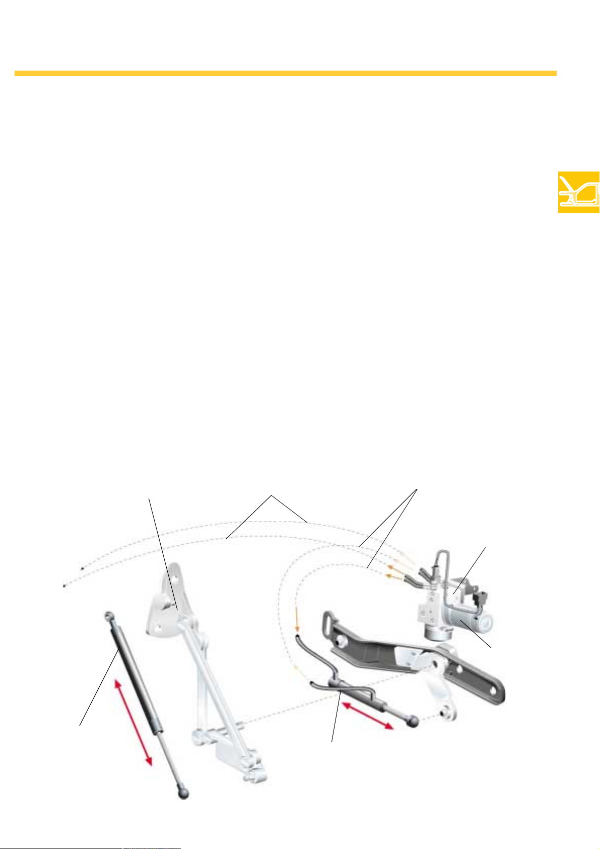
The power-assisted closing is based on an electro-hydraulic system. Oil is pumped into the
hydraulic line system by an electric pump. The
feeding of oil to the piston or piston-rod end of
the hydraulic cylinder facilitates the opening or
closing of the flap via a driving shaft at the door
hinge. The pump is incorporated at the right of
the tail section.
Opening
To open the tailgate, operate either the switch in
the door panelling, the microswitch in the VW
emblem on the tailgate or the radio-wave remote
control.
The switch in the tailgate serves the purpose of
closing the tailgate.
Safety equipment
The power-assisted closing has an anti-trap feature. If the electric motor in the hydraulic component perceives resistance which exceeds a
defined level, power-assisted closure is not
merely stopped but reversed* a little in order to
release the jammed object. The same procedure
is adopted when opening. If, for example, it hits
a low garage roof, the motor stops for a moment.
However, the tailgate then remains in this position without reversing. Renewed actuation is then
required.
*moves back
Door hinge
Gas-assisted shock
absorber
Oil supply, left
hydraulic element
Oil supply, right
hydraulic element
Hydraulic
component
Electric motor
Hydraulic cylinder
270_122
19
Page 20
Bodywork
The sliding roof
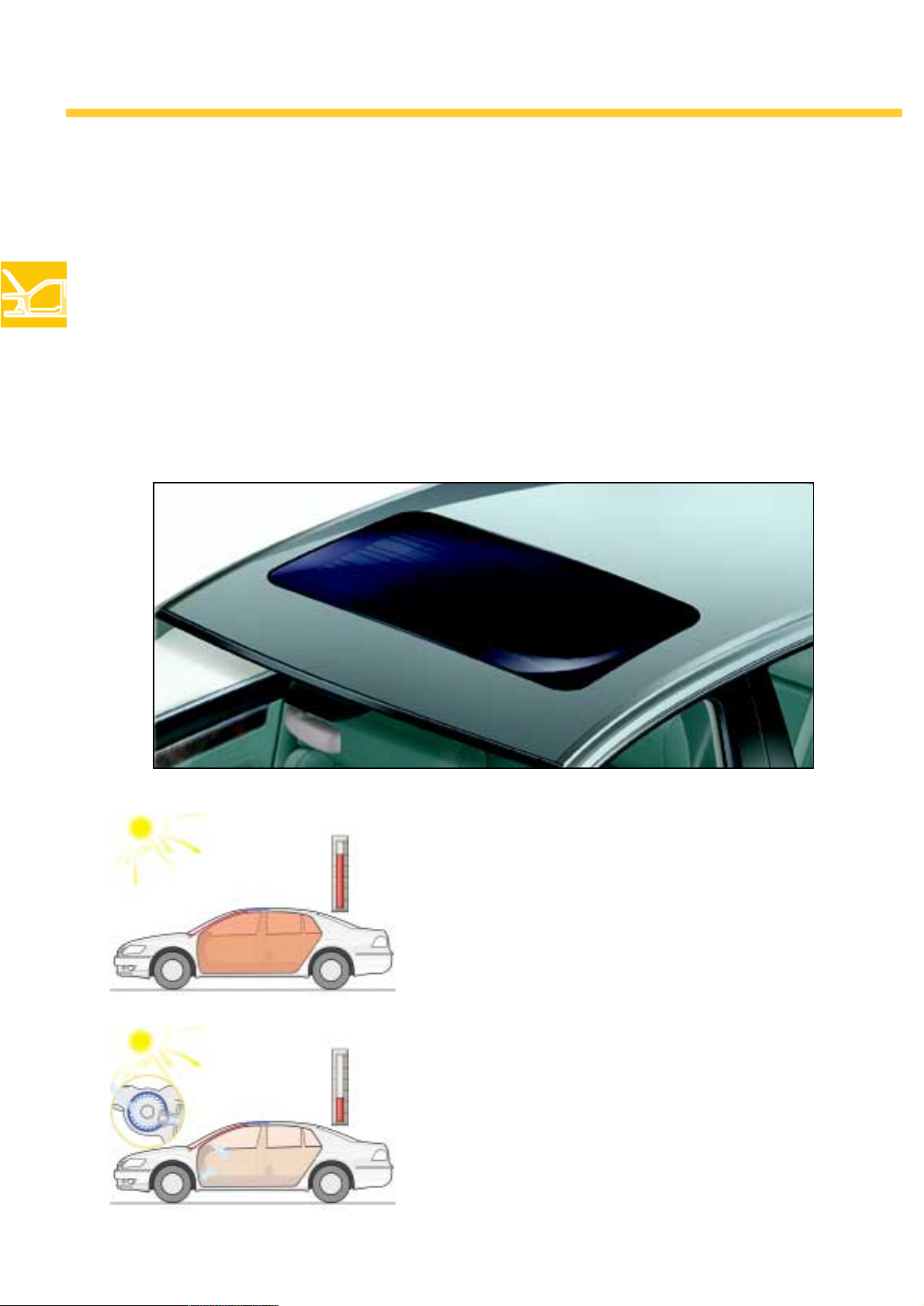
The Phaeton is available with a solar sliding roof with a fixed inside roof lining and a sliding roof / lifting
roof with a separate electrically-sliding inside roof lining.
Solar sliding roof
The solar roof's 28 monokristallin solar cells supply an electrical output of 37 watts. This energy is used to
operate the interior ventilator which is capable of reducing the temperature by up to 20 °C, when the
vehicle is parked, by feeding fresh air into the vehicle's interior.
270_124
270_125
270_177
If the interior ventilation has been activated via
the Infotainment system, the interior ventilator
starts operating when there is sufficient sunlight.
This cools down the interior at high temperatures.
The circulation of air prevents the windows from
misting in winter.
20
Page 21

Sliding roof / lifting roof with solar shading and an electrical wind deflector
A separate electric motor moves the inside roof
lining at the same time as the glass roof is
opened or closed. This can also be adjusted
regardless of the glass roof's position.
All closing procedures are electronically monitored and have an anti-trap feature.
270_166
Depending on the driving speed and the roof opening, the wind deflector is controlled electromechanically in order to prevent wind noise and draughts.
270_167
21
Page 22
Seats
The front seats
The Phaeton is also available with air-conditioned seats. Air-conditioning is provided
through the interaction between the seat heating
and ventilators.
The ventilators, which are integrated in the seat
frames, feed the air heated by the seat heating
to the occupants through fine perforations in the
seat leather. The massage function is imple-
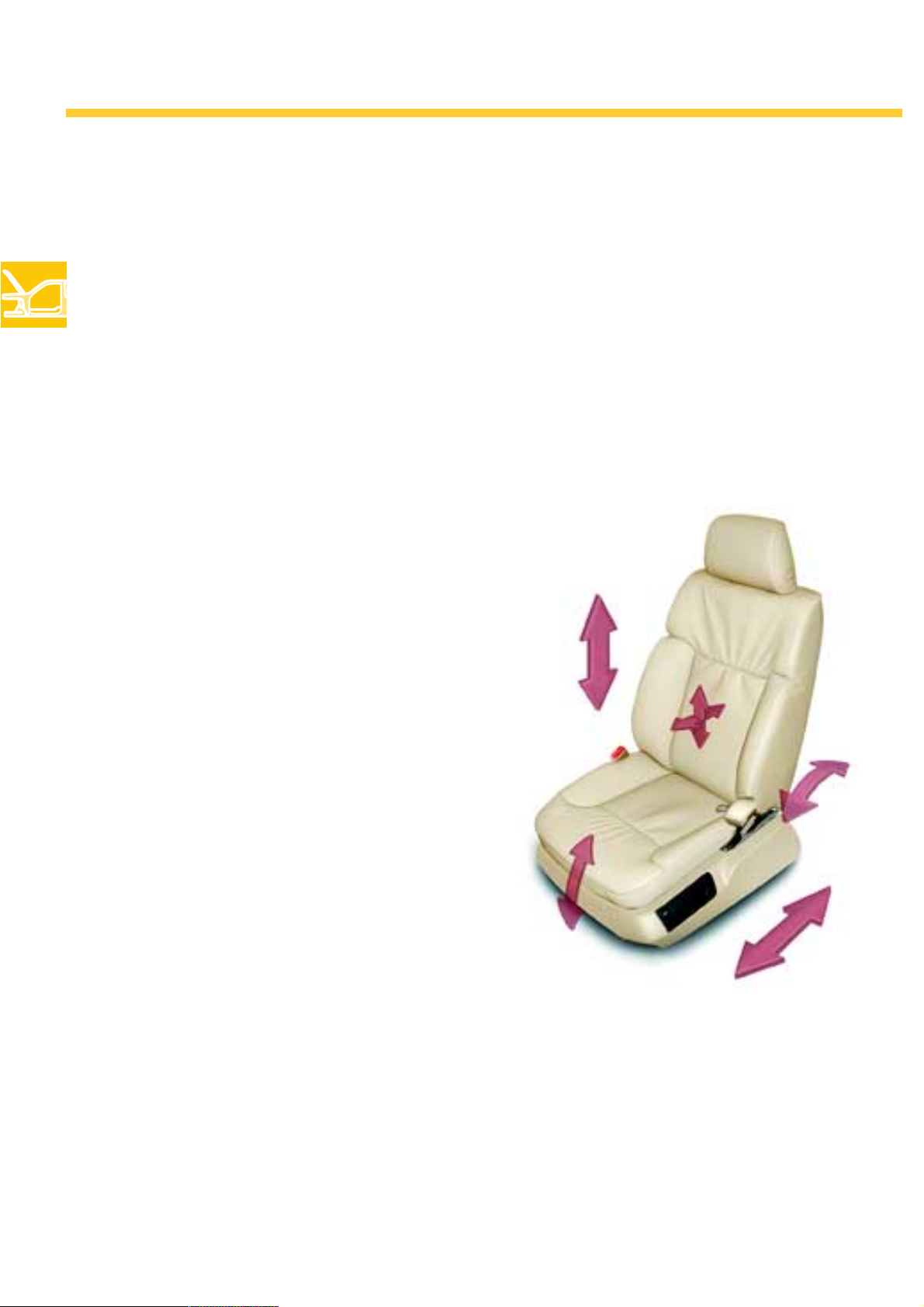
The 12-position seat
Adjustment function
As standard, the Phaeton comes with 12-position
seats. The following functions are electrically
adjustable: longitudinal direction, seat height
and inclination, as well as the backrest inclination. Furthermore, the movement direction of the
lumbar support is adjustable both backwards/
forwards and up/down.
mented by a slow adjustment of the lumbar support. The belt mechanism integrated in the seat
endows the Phaeton with an even greater level of
comfort. Furthermore, the optional second automatic belt in the 18-position seat gives increased
belt comfort and improved safety. The Phaeton
also has an active headrest system (AKS).
Memory functions
The memory package for the 12-position seats
includes a range of saveable functions. In addition to the seat settings, the memory function can
also save the positions of the steering column,
the mirror and the seat belts.
Easy-entry function
The easy-entry function facilitates the convenient
getting in and out of the vehicle by automatically
moving the steering column into its uppermost
and furthest-forward position.
Air-conditioning / massage function
Air-conditioning in the 12-position seats is provided by ventilators - which are integrated in the
seats - and which feed temperate air through the
fine perforations in the leather. The massage
function is implemented through the mechanical
270_147
4-position lumbar support.
The lumbar support is moved automatically up
and down, thus facilitating the relaxation of the
spine and back muscles.
22
Page 23
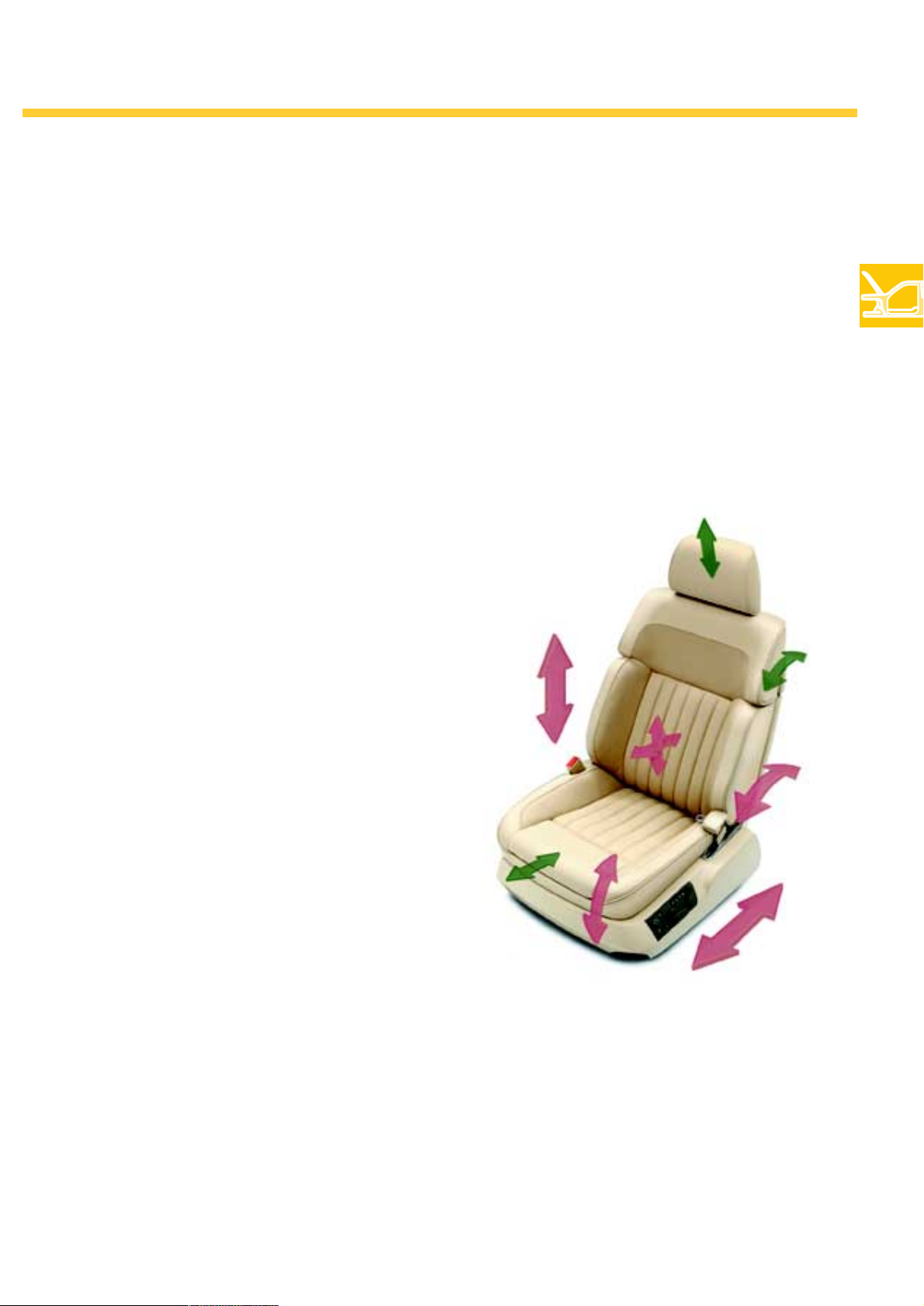
The 18-position seat
Adjustment function
As an optional extra, the Phaeton comes with
high-quality 18-position seats.
They also offer the option of adjusting the backrest head and the seat depth, as well as an electrical adjustment of the headrest.
The 18-position seat can be equipped with an
automatic lap belt on request.
Memory functions
In addition to the functions featured in the 12position seat, the memory package for the 18position seat also offers the option of saving the
positions of the headrest, the seat depth and the
backrest head.
Air-conditioning / massage function
The range of air-conditioning functions in the
18-position seats is equivalent to that of the
12-position seats.
270_146
23
Page 24
Seats
The rear seats
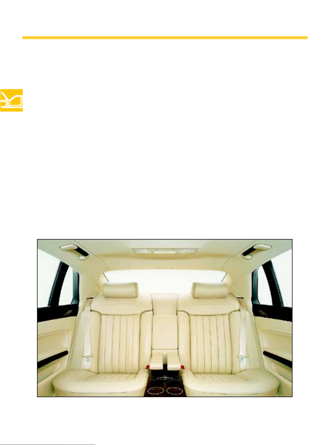
The Phaeton comes with three seating versions for rear-seat occupants:
individual seats, back seat and the 'Premium' back seat
The individual seats
The Phaeton version with the 18-position seat also
comes with the option of 10-position individual
rear seats.
The individual seats can be adjusted electrically
with regard to longitude and inclination. The
headrests and 4-position lumbar support are
also electrically adjustable. The individual seats
are air-conditioned with temperate air which is
fed through the perforations in the leather.
Moreover, the memory function in the version
with individual seats also offers the option of
saving several seat positions.
The control unit for the rear seats is incorporated
into the centre console at the rear.
This is also the location of the control dial for the
rear seat heating. Moreover, the passenger seat
can be moved forward with a separate button.
24
270_050
Page 25
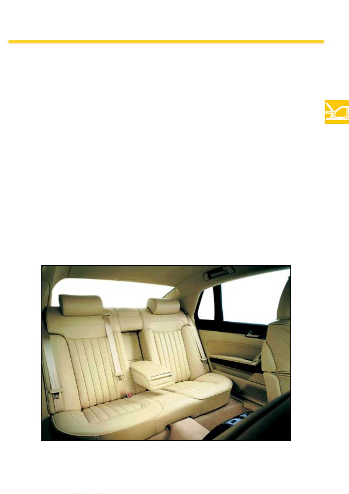
The back seat
The back seat in the standard version can comfortably accommodate three people. Side airbags and manual headrests (adjustable in height
and inclination) are also provided.
The following features have been added to the
comfort-orientated 'Premium' back seat system:
electrical lumbar support in the outside seats
including ventilation, massage and seat heating,
as well as headrests whose height can be electrically adjusted.
The controls for the rear seats are attached laterally to the seat cushion.
The control dials for the back seat heating are
located in the centre console at the rear.
Moreover, the passenger seat can be moved forward with a separate button.
270_143
25
Page 26
Passenger protection
General passenger protection
The Phaeton has sophisticated active and passive
safety equipment. Volkswagen has redefined
safety standards in luxury class cars by deploying lighter but high-strength materials, improved
deformation features, curved edges and shatterproof plastics, all-round safety glazing, improved
airbag sensory mechanism and optimised belt
tensioning systems. Phaeton not only places an
Airbag systems
The Phaeton is equipped with 4 different airbag
systems. All airbags are triggered by the airbag
control unit which registers the gravity of the
accident via the early-crash sensors, thus preventing the unnecessary triggering of the airbags
in the event of a minor accident. Details of the
type and gravity of a collision are fed to the control unit by sensors which are located at the front
headlight mounting.
emphasis on your own safety, but also on the
safety of other vehicles involved in the event of a
collision. The improved deformation behaviour
of the Phaeton's bodywork decreases the damage incurred by other vehicles involved in an
accident situation.
Furthermore, all airbags are 'depowered' in
order to prevent injury when the air sacks are
being opened.
'Depowered' means that the airbag opening
flaps and the folding of the airbags have been
optimised to an extent which reduces the agressive effect of the triggering of the airbags on the
occupants.
26
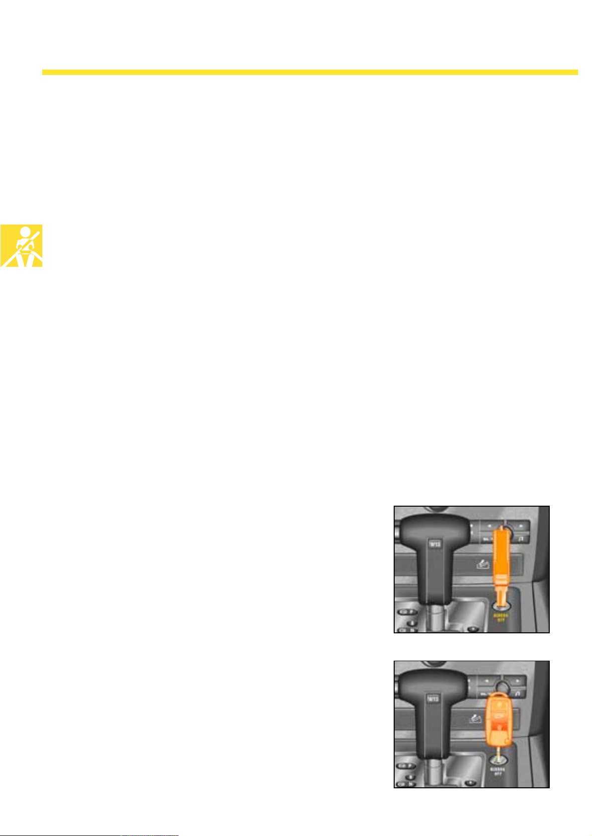
Airbag deactivation
The front and side airbag for the front passenger
can be deactivated with the ignition key. For this
purpose, a lock is located in the centre console
next to the selector for the automatic transmission. Here one can use the ignition key to select
one of two positions (Airbag on/Airbag off).
On the other hand, the side airbags at the rear
and the head airbag at the passenger side cannot be deactivated. However, they only receive a
trigger signal from the airbag control unit when
the lateral crash sensors register a corresponding
impact.
270_192
270_193
Page 27
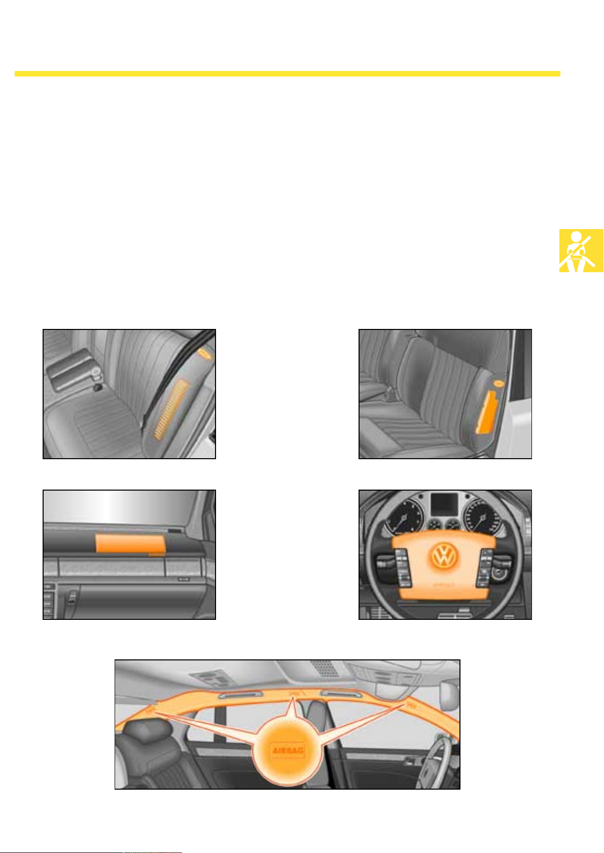
The Phaeton is available with the following airbag systems:
- Driver and front passenger
airbag (ca. 75l/120l),
- Side airbag at front and rear (ca. 12l),
- Head airbag (ca. 31l).
of a crash by an internal and two external longitudinal acceleration sensors. The side airbags
are triggered by the airbag control unit which
has one internal and four external traverse
acceleration sensors at its disposal. The head airThe driver and front passenger airbags are triggered by the airbag control unit. The control unit
bags are triggered electrically in conjunction
with the side airbags.
is fed information regarding the type and gravity
Rear side airbag Front side airbag
Front passenger airbag Driver airbag
270_023 270_025
Head airbag
270_026270_019
270_024
27
Page 28

Passenger protection
Belt system
All seats on the Phaeton possess three-point
retracting seat belts with belt tension limiters. Furthermore, all outside seats are fitted with pyrotechnical seat belt tensioners which are triggered
by the central control unit if the gravity of the
accident is deemed sufficient.
The 18-position seat version is also available with
an optional belt system which is fitted with an
The comfort mechanism
on the shoulder belt tensioner
A force greater than that used in conventional
belt buckles is required in order for the automatic
'Rollgurt' to retract the compound insertion
tongue into its starting position in the double
retractor system on the 18-position seat. However,
in order not to transmit this force to the vehicle
occupants, a mechanism in the automatic shoulder seatbelt is used which can vary the force
exerted on the belt.
additional automatic lap belt. This extra automatic belt is attached to the side of the seat. In
conjunction with the automatic shoulder seatbelt,
it facilitates the simultaneous tightening of the
belt in the occupants' shoulder and lap area. In
the event of a collision, this leads to an early and
extremely effective coupling of the occupants
and vehicle.
If a seat allocation is recognised by means of a
belt buckle check, the mechanism reduces the
force in the automatic shoulder seatbelt when it
is being used. This prevents the seatbelt from
exerting too much pressure on the occupant's
upper body. The full force is once again available when the seatbelt is released.
The mechanism is incorporated into the automatic shoulder seatbelt.
28
Comfort
mechanism
270_033
Page 29
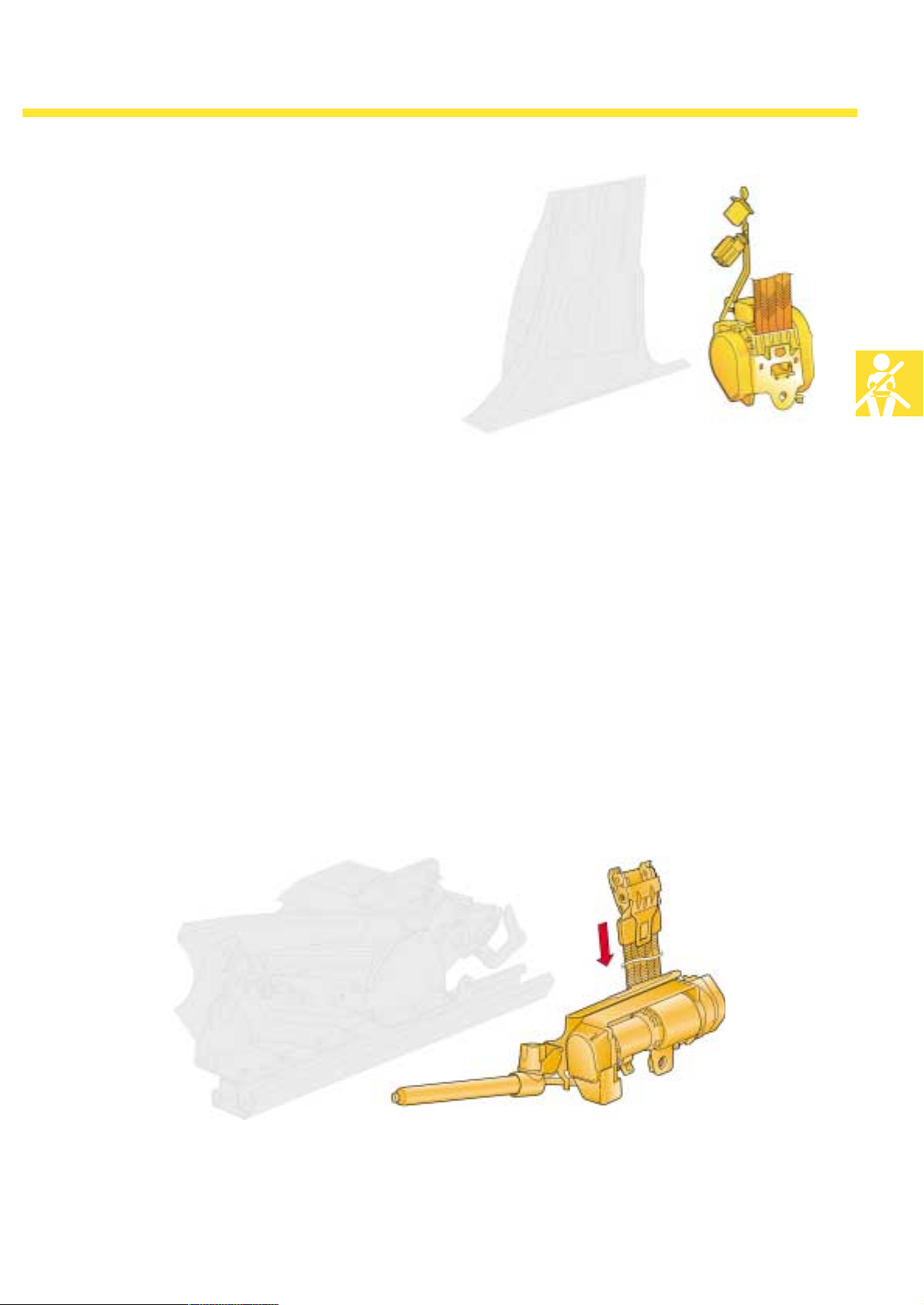
Front automatic shoulder seatbelt
In the standard version — the 12-position seat —
an automatic shoulder seatbelt ensures optimal
safety. This means that in the event of a collision,
the seatbelt is tightened around the occupant's
shoulders via the B-pillar.
The shoulder belt has a spherical tensioner.
Automatic lap belt (optional)
270_220
The second automatic belt, which is attached to
the side of the seat in the 18-position seat, affords
increased safety as it simultaneously applies
additional tension to the lap belt along with the
automatic shoulder seatbelt. The automatic lap
belt also results in an increase in comfort as it is
attached to the seat and is suitable for all seat
positions. The ensuing increase in freedom of
movement brought about by this gives one the
sensation of not being belted in.
270_034
29
Page 30
Passenger protection
Headrests
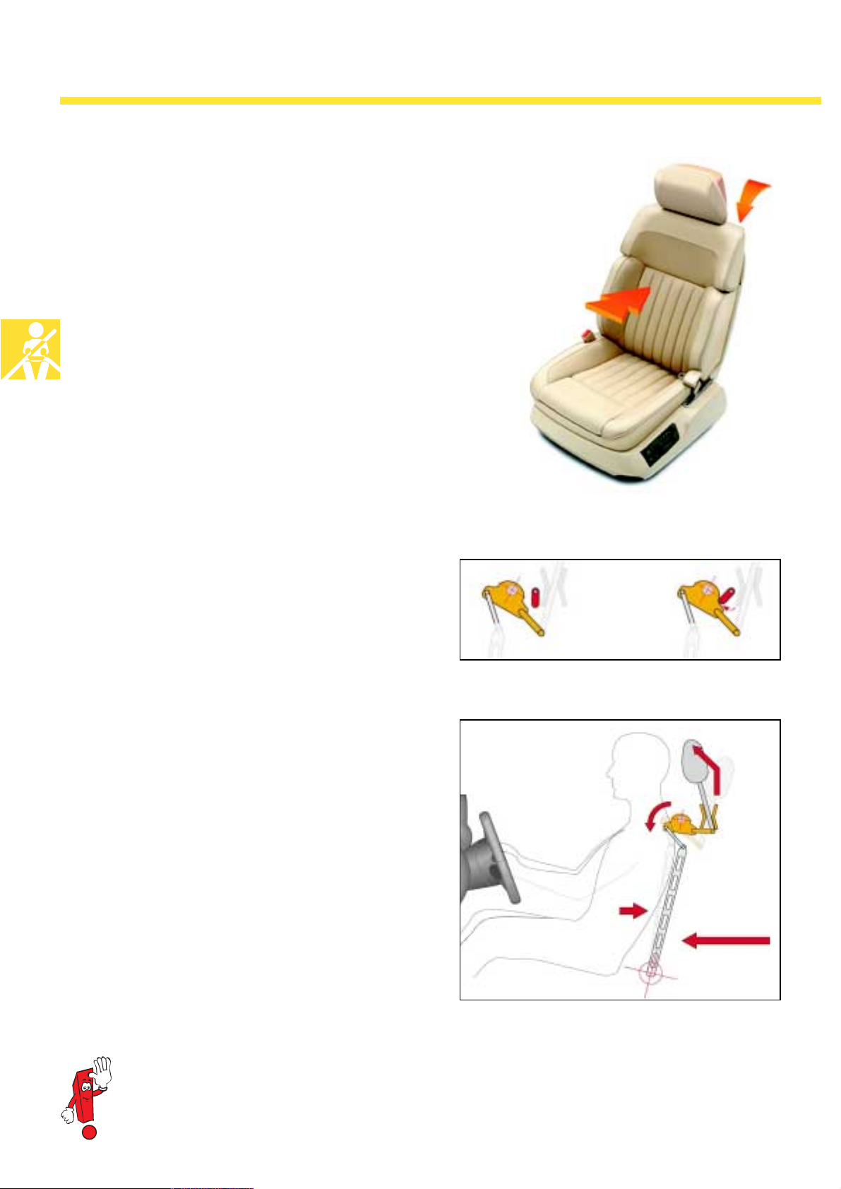
The front seats in the Phaeton are fitted with an
active headrest system (AKS). Through a forward
displacement of the headrests and the ensuing
avoidance of relative accelerations between the
shoulders and the head, this system lowers the
risk of cervical spine injury in the event of a
crash. The reversible system continues to be fully
operable after the triggering of the AKS.
270_018
The mode of operation
The AKS is triggered only by a collision at the
vehicle's rear. In the event of a frontal crash, its
triggering is prevented by a safety block.
If an accelerating force in the travelling direction
is applied to the rear of the vehicle, the movement of the occupants is delayed by inertia. The
body is therefore pushed into the seat. Due to this
increased pressure on the backrest, a bent lever
is turned in a way which causes the headrest to
move upwards and forwards. This direction is
determined by a rail guide in which the headrest
is located.
Impeding weight
270_102
30
270_101
The full range of functions as well as the correct protective function of the active headrest system
requires a body-specific seat setting for the respective occupants.
Page 31
Installation/removal
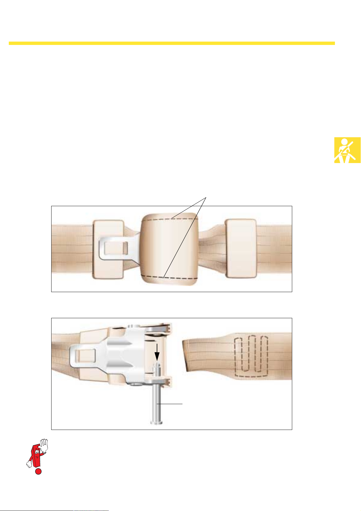
(Only applies to 18-position seats with the 'lap-belt tensioner' option.)
The seatbelt has to be separated from the seat in
order to remove the seats. This is done by
detaching the insertion tongue's plastic covering
and the subsequent removal of the metal pin
which is secured with a sheet metal lock. As seen
in the illustration, the insertion tongue's housing
Original closed state
is sawn open at the two joints with a little hack-
saw. The topside can then be removed.
Once the pin has been removed, the belt can be
separated from the insertion tongue and the seat
can be removed.
Saw the joints
270_160
Opened state with removed metal pin
Remove the pin
270_161
When carrying out assembly tasks on the lap-belt winders, please ensure that the underpart of
the housing is not damaged!
If damage should occur, the complete lap-belt winder is to be replaced!
31
Page 32
Engines
The Phaeton engines
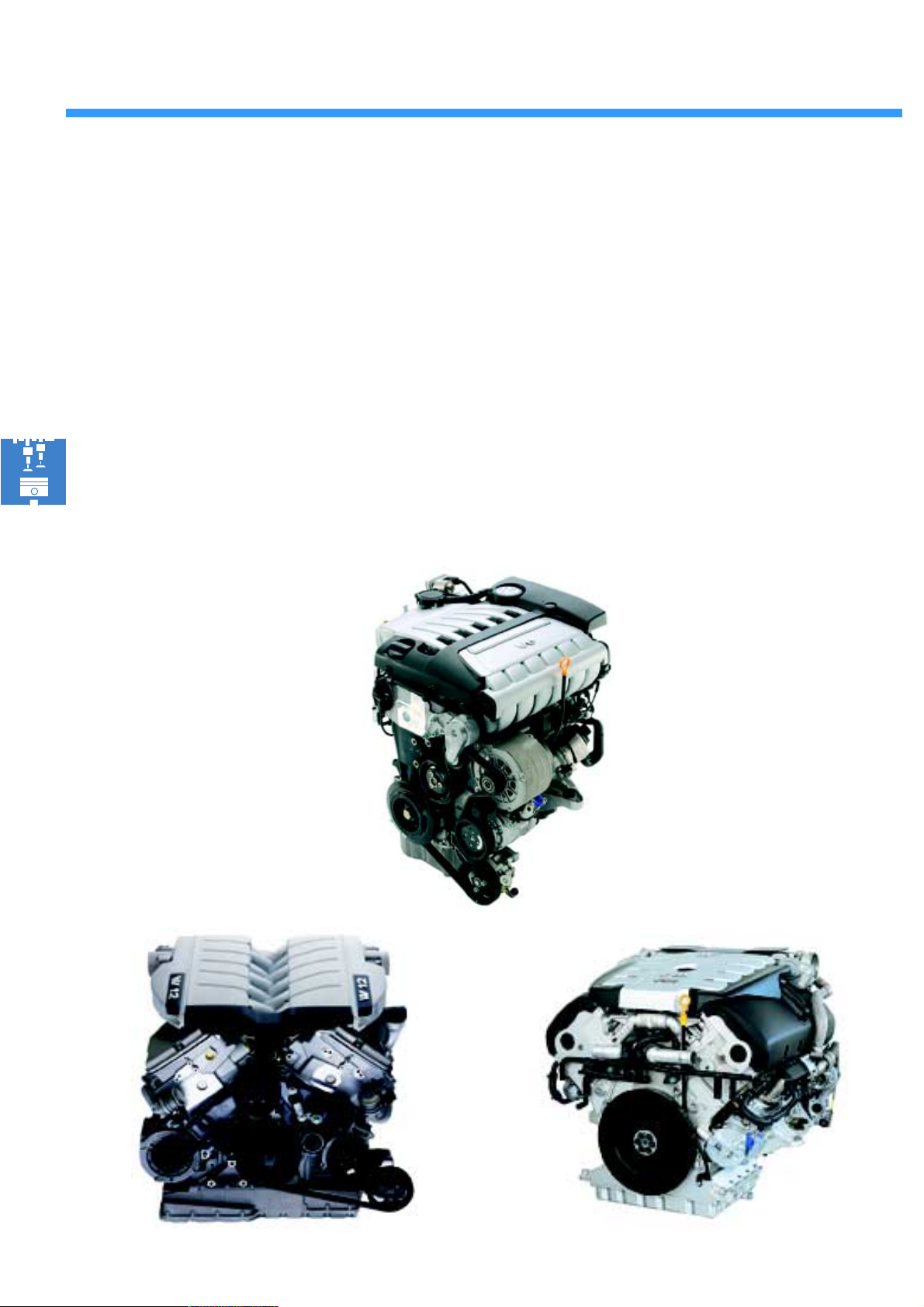
The Phaeton is available with a choice between
two petrol engines and one diesel engine.
The entry-level motor is a 3.2l V6 petrol engine.
This motor is an advancement of the 2.8l V6 petrol engine.
The launch of the Passat W8 witnessed the introduction of a new Volkswagen engine series:
W-engines. The absolute highlight of this engine
3.2l V6 petrol engine
series — a W12 petrol engine with a 6.0l displacement — is available in the Phaeton. All petrol engines work with 4-valve technology and
conform with the EU4 exhaust emission standard.
A 5l V10 TDI diesel engine with a pump-jet injection system is the top engine version available in
the Phaeton.
It is the most powerful series passenger-vehicle
diesel engine in the world.
32
6.0l W12 petrol engine 5l V10 TDI engine
270_142
270_058270_056
Page 33
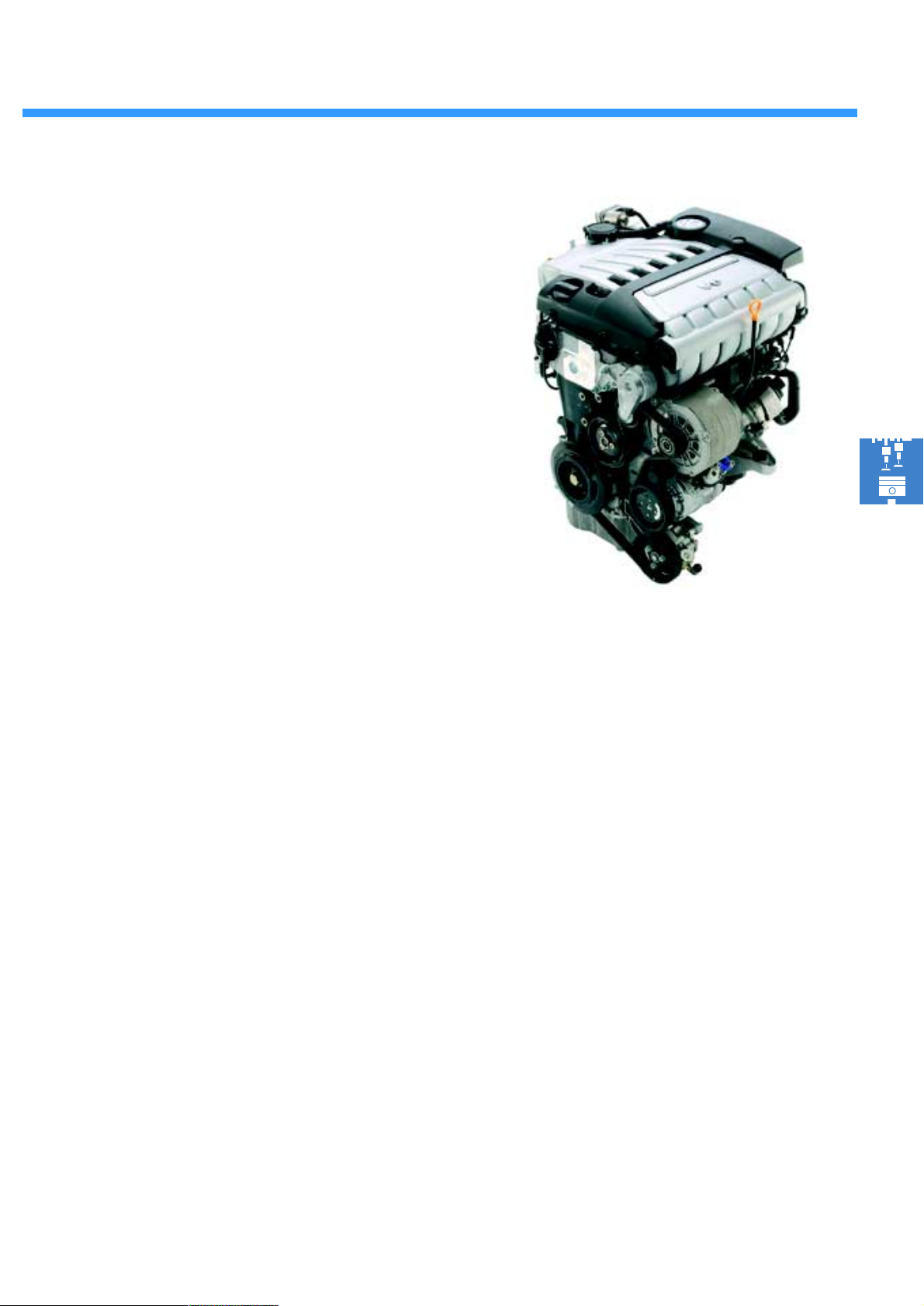
The 3.2l V6 petrol engine
is an advancement of the Volkswagen 2.8l V6
engine. The construction principle of applying a
narrow V-angle of 15°, and its associated advantages resulting in a low overall length and width,
has been adhered to. The displacement increase
to 3.2l, in conjunction with its first-ever longitudinal mounting in a vehicle, required a complete
overhaul of the engine. The engine's increased
displacement was rendered possible by extending the piston stroke while simultaneously augmenting the cylinder bores.
Innovations in engine mechanics with respect to the 2.8l V6 petrol engine
270_142
● Continuous intake and exhaust camshafts - adjusted by vane pump regulator
● Intake and escape channels with considerably increased flow capacity
● Inlet and escape valves with enlarged diameter
● Crankshaft with enlarged stroke
● Cylinder crankcase with larger bore
● Optimised variable intake manifold with pressure-regulated crankcase ventilation
● Water-cooled alternator
● Oil filter and cooler unit integrated in the engine bracket
Technical features of the “Bosch Motronic ME 7.1.1” engine management system
● Electrical throttle valve operation
● Constant Lambda regulation by 4 Lambda sensors with 2 pre-catalytic-converters and
2 post-catalytic-converters
● Control of the inner exhaust gas recirculation via the camshaft adjustment
● Secondary air injection
● European On Board Diagnostic System (EOBD) with exhaust gas indicator light
● Electronically-regulated fan control
33
Page 34
Engines
Technical data 3.2l V6 engine
Engine code AYT
Construction VR engine
Displacement 3189 cm
Bore 84 mm
Stroke 95.9 mm
Compression ratio 11.25:1
Valves per cylinder 4
Max. output 177 kW at 6200 1/min.
Max. torque 315 Nm at 2400 1/min.
Engine management Bosch Motronic ME 7.1.1
Fuel ROZ 98 (reduced performance with ROZ 95)
Exhaust treatment Three-way catalytic converters with constant Lambda regulation
3
Exhaust emission standard EU 4
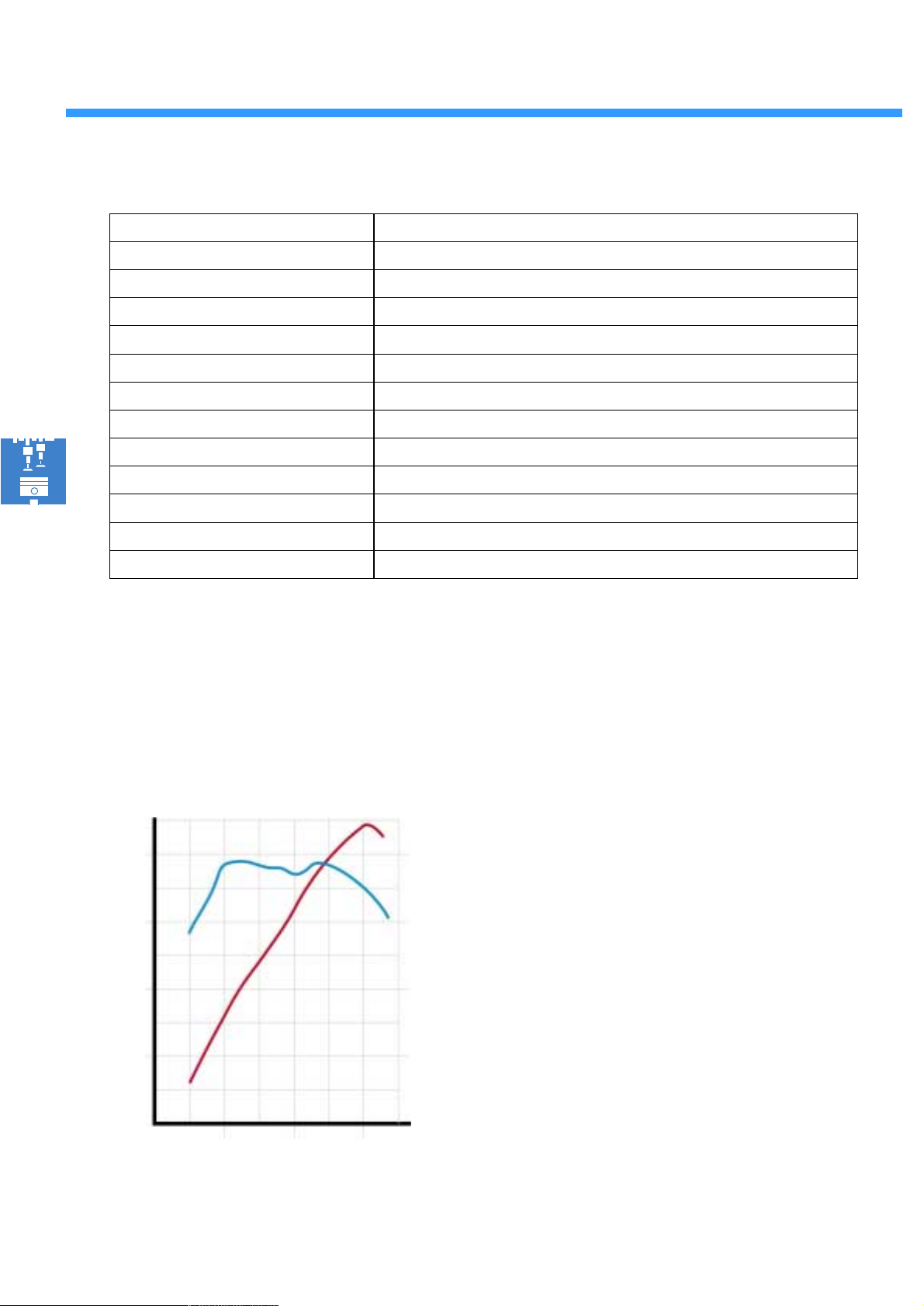
Torque and performance chart
Torq ue (Nm) Pe rforma nc e (kW)
360
320
280
240
200
160
120
160
120
100
180
140
80
60
The 3.2l V6 engine achieves its maximum
torque of 315 Nm at an engine speed of just
2400 1/min.
This facilitates changing up to the next gear at
low engine speeds, thus increasing fuel efficiency.
The nominal output of 177 kW/241 bhp is
achieved at 6200 1/min.
34
80
40
0
2000
4000 6000
40
20
1/min.
270_032
Page 35
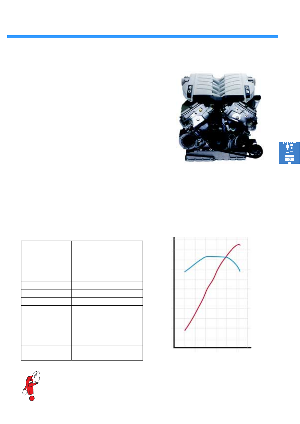
The 6.0l W12 petrol engine
With the W12 engine, Volkswagen is offering a
12-cylinder engine in its range for the first time
ever. It is the most powerful engine version available in the Phaeton.
Engine mechanics technical features
● Cylinder block made of aluminium
● Bottom crankshaft bearing in grey cast iron
bearing blocks
● Oil pump driven by a chain
● Very com p act en gin e
Engine management technical features
● Two motor controllers
● Secondary air injection
● Exhaust gas recirculation
Technical data
Engine code BAN
Construction W engine
Displacement 5998 cm
Bore 84.0 mm
Stroke 90.186 mm
Valves per cylinder 4
Compression ratio 10.75:1
Max. output 309 kW at 6000 1/min.
Max. torque 550 Nm at 3500 1/min.
Engine management Bosch Motronic M 7.1.1
Fuel ROZ 98
Exhaust treatment Three-way catalytic converter with
constant stereo Lambda regulation
Exhaust emission
standard
EU 4
3
270_056
Torque and performance chart
Torque (Nm) Performance (kW)
660
600
540
480
420
360
300
240
180
120
60
0
2000
4000 6000
330
300
270
240
210
180
150
120
1/min.
90
60
30
270_172
Please refer to the self-study programmes nos. 248 and 250 for detailed information on the
W engine concept.
35
Page 36
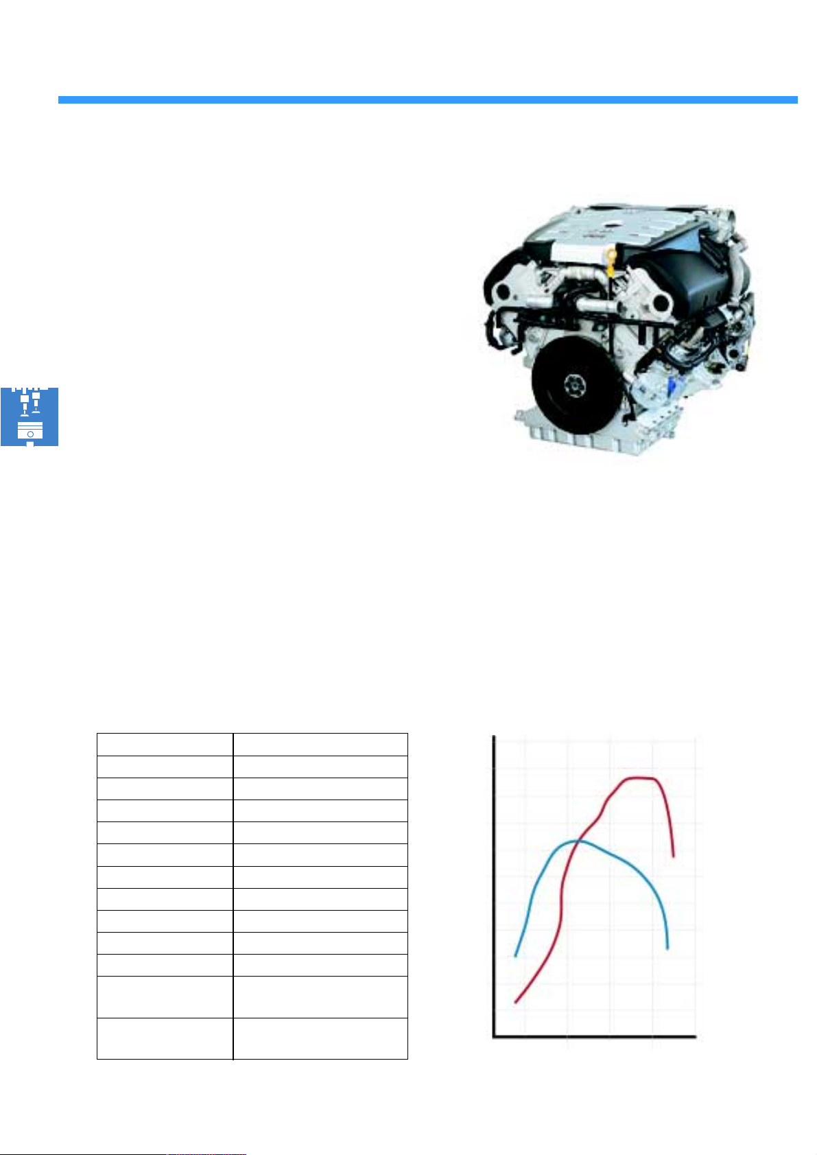
Engines
The 5l V10 TDI engine
The V10 TDI engine is a recently developed diesel engine. Combining an innovative lightweight
construction with enormous power, it is equipped
with the pump-jet injection system.
Engine mechanics technical features
● Cylinder block made of aluminium with a
grey cast iron bearing tunnel
● Joining of cylinder head and cylinder
block via tie-rod screw connection
● Balancer shaft for reducing vibrations
● Control and ancillary unit driven by
gearwheels
Engine management technical features
● Two motor controllers
● Charged by two adjustable turbochargers
Technical data
Engine code AYH
Construction V engine, 90° V-angle
Displacement 4921 cm
Bore 81 mm
Stroke 95.5 mm
Valves per cylinder 2
Compression ratio 18.5:1
Max. output 230 kW at 4000 1/min.
Max. torque 750 Nm at 2000 1/min.
Engine management Bosch EDC 16
Fuel Diesel 49 CZ min. or biodiesel
Exhaust treatment Exhaust gas recirculation and
oxidation catalytic converter
Exhaust emission
standard
EU 3
3
270_058
● Exhaust gas recirculation effected with
pneumatically-controlled exhaust gas
recirculation valves in conjunction with
Torque and performance chart
Torq ue (Nm) Pe rforma nc e (kW)
1000
800
600
400
200
0
2000
3000
4000
1/min.
250
200
150
100
50
0
36
270_173
Page 37
The fuel tank
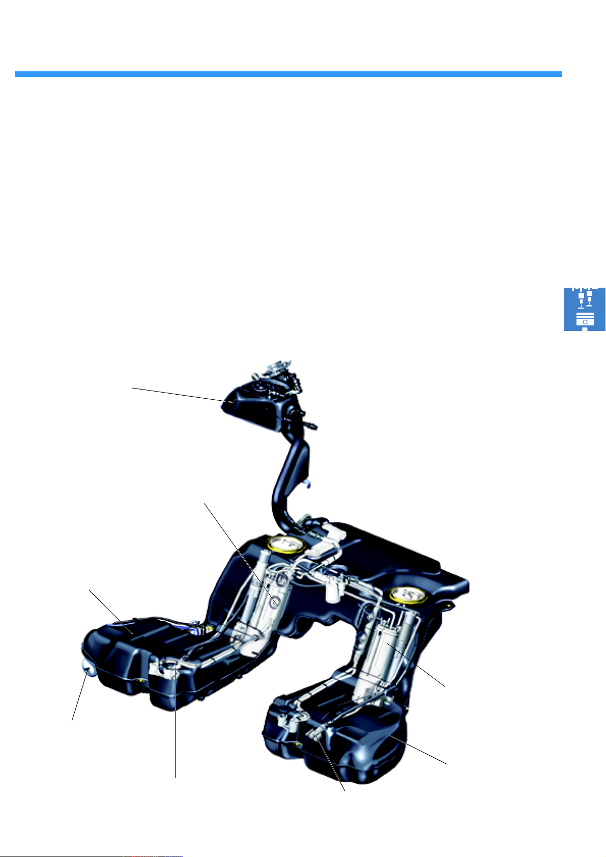
The fuel tank is mounted on the vehicle's underbody close to the rear axle. It has a filling volume
of 90 litres. Due to its external shape, it consists
of a main and secondary chamber.
Both fuel tank chambers have an electrical fuel
pump and a sucking-jet fuel pump.
Reserve tank
(only in vehicles with petrol engine)
Each electrical fuel pump is assigned two send-
ers for fuel supply, a fuel sender and a lever
sender.
The four senders for fuel supply directly transmit
their signals to the dash panel insert.
Main chamber
Fuel filter
270_112
Fuel pump 1
Sucking-jet pump 1
Fuel pump 2
Secondary
chamber
Sucking-jet pump 2
37
Page 38
Automatic transmission
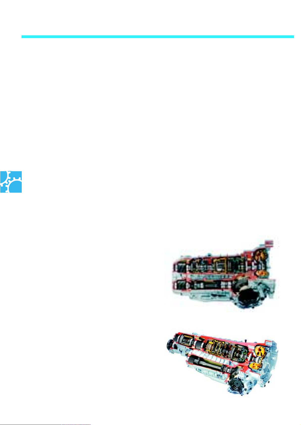
The automatic transmission
Depending on the engine, the Volkswagen Phaeton is fitted with one of two 5-speed automatic transmissions or a 6-speed automatic transmission.
The 5-speed automatic transmission
Both 5-speed automatic transmissions are currently already in use in other vehicles from the
Volkswagen Group. They have been modified
and adapted for installation in the Phaeton. An
electronic/hydraulic system is used for controlling the two automatic transmissions.
Furthermore, both 5-speed automatic transmissions have:
- a dynamic shift programme and also a sport programme,
- a regulated torque converter lockup clutch,
- and a Tiptronic shift programme with steering wheel switches.
The 5-speed automatic transmission 01V
Installed in the front-wheel drive Phaeton in conjunction with the
To this end, the automatic transmission's control
unit registers operating conditions, the driver's
wishes as well as external influences such as
travelling uphill or downhill. Shifting between the
5 gears is effected by the control unit with
regards to all incoming data.
- 3.2l V6 engine.
Maximum torque transmission: 310 Nm
The 5-speed automatic transmission 01L
Installed in the Phaeton 4-Motion with the
6.0l W12 engine.
A Torsen centre differential (PAT) is integrated in
the gearbox in order to distribute the torque to
all four wheels.
Maximum torque transmission: 560 Nm
270_104
270_105
38
Page 39
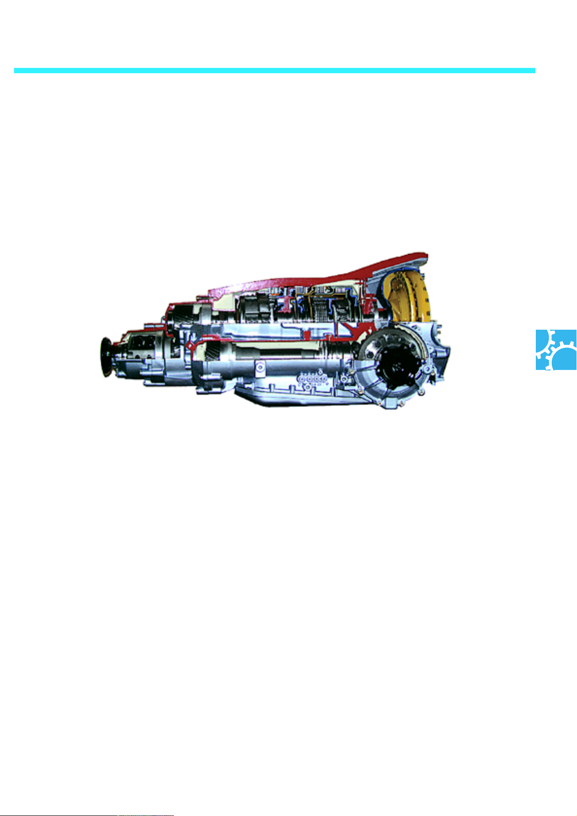
The 6-speed automatic transmission
The Phaeton is the first Volkswagen vehicle to be
fitted with a 6-speed automatic transmission.
The specially-developed automatic transmission
is installed in the Phaeton in conjunction with the
new 5l V10 TDI engine with 4-Motion.
Compared with the 5-speed automatic transmis-
Technical features
sions, it is especially characterised by:
Gearbox description: 09F
- an improved driving performance,
- a reduction in fuel consumption and
Max. input torque: 750 Nm
exhaust emissions,
- a weight reduction of approx. 14 kg,
- a reduction in the number of components by
approx. 30% and by a high shifting
spontaneity with excellent shifting quality.
Furthermore, the automatic transmission has:
- a dynamic shift programme and also a sport programme,
- a regulated torque converter lockup clutch and
- a Tiptronic shift programme with steering wheel switches.
270_135
39
Page 40
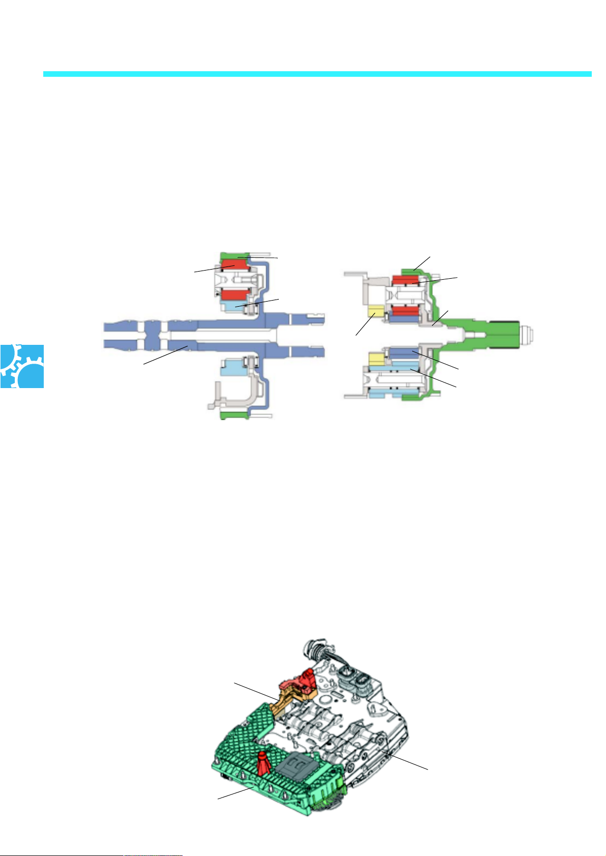
Automatic transmission
The six automatic transmission gears are shifted via a Ravigneaux planetary gear set with a series-connected simple planetary gear set.
This arrangement is known as the Lepelletier gear-set concept.
Lepelletier gear set
Simple planetary gear set Ravignaux planetary gear set
Internal gear 1
Planet gear
Sun gear 1
Turbine shaft
Control of the automatic transmission is effected
by a control unit known as mechatronics. This is a
combination of an electronic control unit and a
hydraulic switching device (control valve assembly).
Gear changes can be controlled more exactly
than before due to mechatronics. This provides
drivers with an optimised shifting quality and an
increased level of driving comfort. Using the
Internal gear 2
Planet gear, short
Planet carrier
Sun gear 2
Sun gear 3
Planet gear, long
270_221
incoming sensor signals, the control unit recognises the current state of the gearbox and the
driver's intention, reacting to these with adjusted
shift points.
Driver wishes ranging from an extremely sporty
to a very economical driving style are recognised
and taken into consideration. Mechatronics is
arranged within the gearbox, located directly at
the control valve assembly.
40
Multifunctional switch F125
Control unit for
automatic transmission J217
Hydraulic switching device
(control valve assembly)
270_240
Page 41
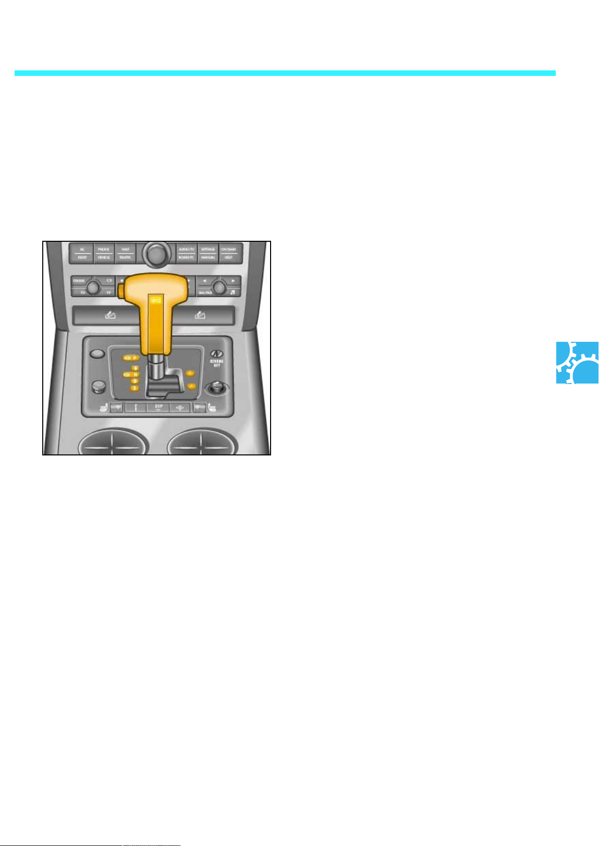
Selector lever positions
The selector lever and Tiptronic functions are the same in the 5-speed automatic transmission and the 6speed automatic transmission.
P - Parking
In order to move the selector lever from the 'P'
position, the ignition has to be turned on and
both the brake and the selector lever's locking
key have to be pressed.
R - Reverse
The brake and the selector lever's locking key
have to be pressed in order to apply the reverse
gear.
N - Neutral
The gearbox is idling in this position. No power is
being transmitted to the wheels.
D - Automatic gear changing
When the selector lever is positioned at 'D', gear
change from gear 1 to 5, or gear 1 to 6 in the 6-
speed automatic transmission, is effected auto-
matically.
S - Sport
In this selector lever position, the automatic trans-
mission shifts according to sporty characteristics.
The gears are extended further and the shift
points occur at higher engine speeds.
41
Page 42
Automatic transmission
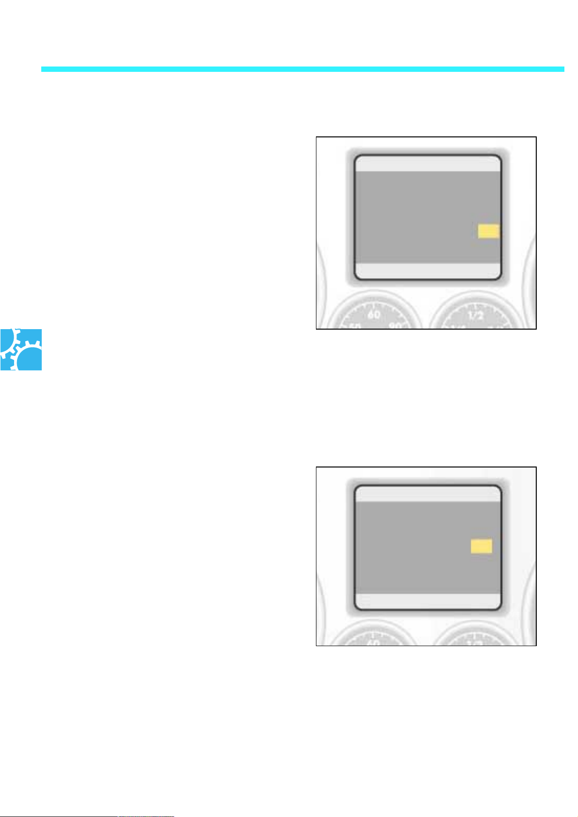
Shift programme and gear indicator in the
dash panel insert
In both the 'D' and 'S' automatic shift programme, the engaged selector lever position and
the gear being currently used are displayed in
the dash panel insert.
P
R
N
D3
S
123.4 km 12.3°C 123456 km
The respective gear being used is displayed in
the dash panel insert if the automatic transmission is in the Tiptronic shift programme.
270_109
P
R
3
D
S
123.4 km 12.3°C 123456 km
42
270_108
Page 43
Tiptronic
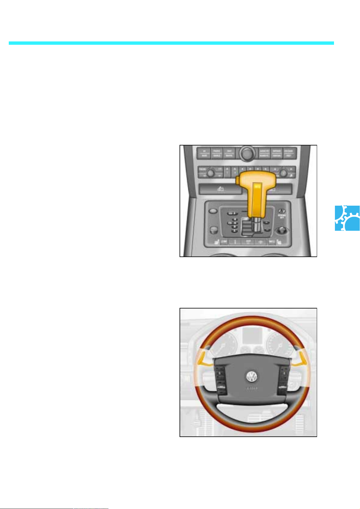
The Phaeton's Tiptronic is available as a selectorlever Tiptronic and also comes with switches on
the steering wheel for operating the Tiptronic.
Selector-lever Tiptronic
The automatic transmission is switched to Tiptronic mode by moving the selector lever from
the 'D' position into the Tiptronic aisle.
Gear change now has to be effected by moving
the selector lever.
Moving the gear-shift lever forward switches up
a gear, moving it back moves down a gear.
Steering wheel - Tiptronic switches
These steering wheel switches, which have been
tried and tested in the world of motor sport, offer
an optimally ergonomic actuation for gear selection. Here you use:
- the switch on the right to move up a gear and
- the switch on the left to move down a gear.
If the selector lever is in the 'D' or 'S' positions
when the steering wheel switches are pressed,
the automatic transmission control moves into
Tiptronic mode. Control automatically reverts to
the previously selected 'D' or 'S' programme if
the steering wheel switches are not pressed
again.
270_029
270_096
43
Page 44
Automatic transmission
The selector lever block
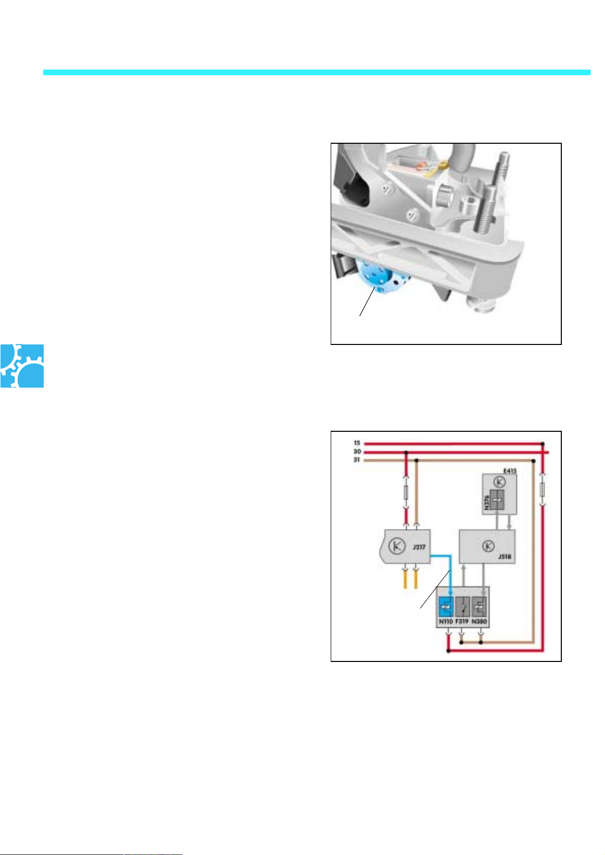
The magnet for selector lever block N 110
is located on the selector lever frame below the
selector lever. It prevents the actuation of the
selector lever from the positions 'P' and 'N' when
the brake is not being applied.
How it works
Once the ignition has been turned on, the magnet for the selector lever block is put under current by the control unit for automatic
transmission, thus blocking the selector lever. If
the control unit receives the signal 'brake
applied', it cuts off current to the magnet and the
selector lever can be moved.
Magnet for selector lever block
CAN-bus signal
'brake applied'
Control of
magnet N110
270_222
44
Effects of drop-out
If one of these two signals fails or if the magnet is
faulty, the selector lever can be moved out of 'P'
and 'N' without applying the brake — when the
ignition is turned on.
270_224
Page 45
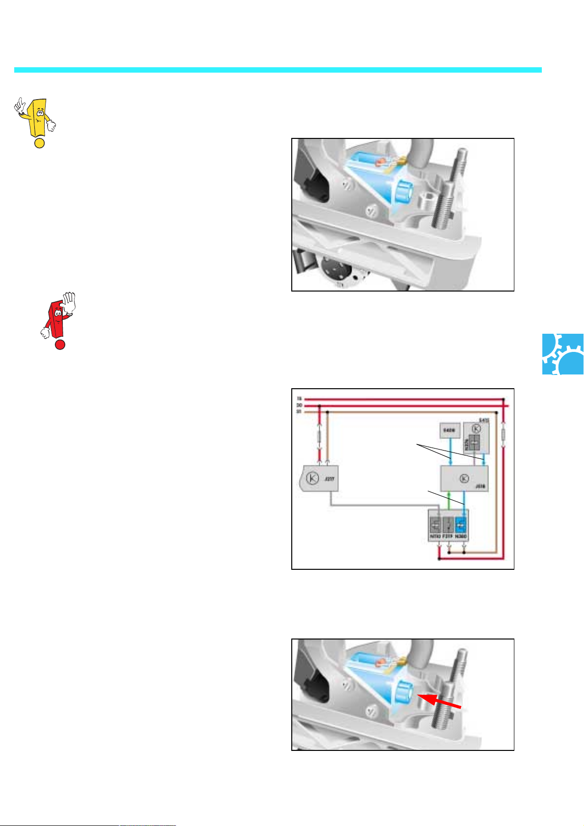
The magnet for selector
lever block 'P' N380
Also located at the selector lever. It prevents the
selector lever from moving out of the 'P' position
when the ignition is switched off. The brake
therefore has to be pressed and the ignition
switched on in order to move the selector lever
from the 'P' position.
It is possible to switch on the ignition via the switch for access and start authorisation and via
the button E408 for access and start authorisation.
How it works
The magnet for selector lever block 'P' is without current when the ignition is switched off, thus disabling
the selector lever in 'P' position. Once the ignition
has been switched on, a signal flows from the switch
for access and start authorisation E415 or from the
button for access and start authorisation E408 to the
access and start authorisation relay J 518. This then
sends current to the magnets for selector lever block
'P' and the disablement is removed. The switch F319
signals to the access and start authorisation relay
that the selector lever is in 'P' position.
270_157
Signal
'Ignition
switched on'
Signal to the
magnets for
selector lever block 'P'
Effect of drop-out
If one of the signals fails or the magnet for selector
lever block 'P' is defective, then the selector lever
cannot be moved out of the 'P' position. The disablement has to be manually unlocked for towing the
vehicle. For this purpose, the selector lever covering
is to be removed and the magnet actuated by hand.
The selector lever has to be simultaneously moved
out of the 'P' position.
270_225
270_157
45
Page 46
Automatic transmission
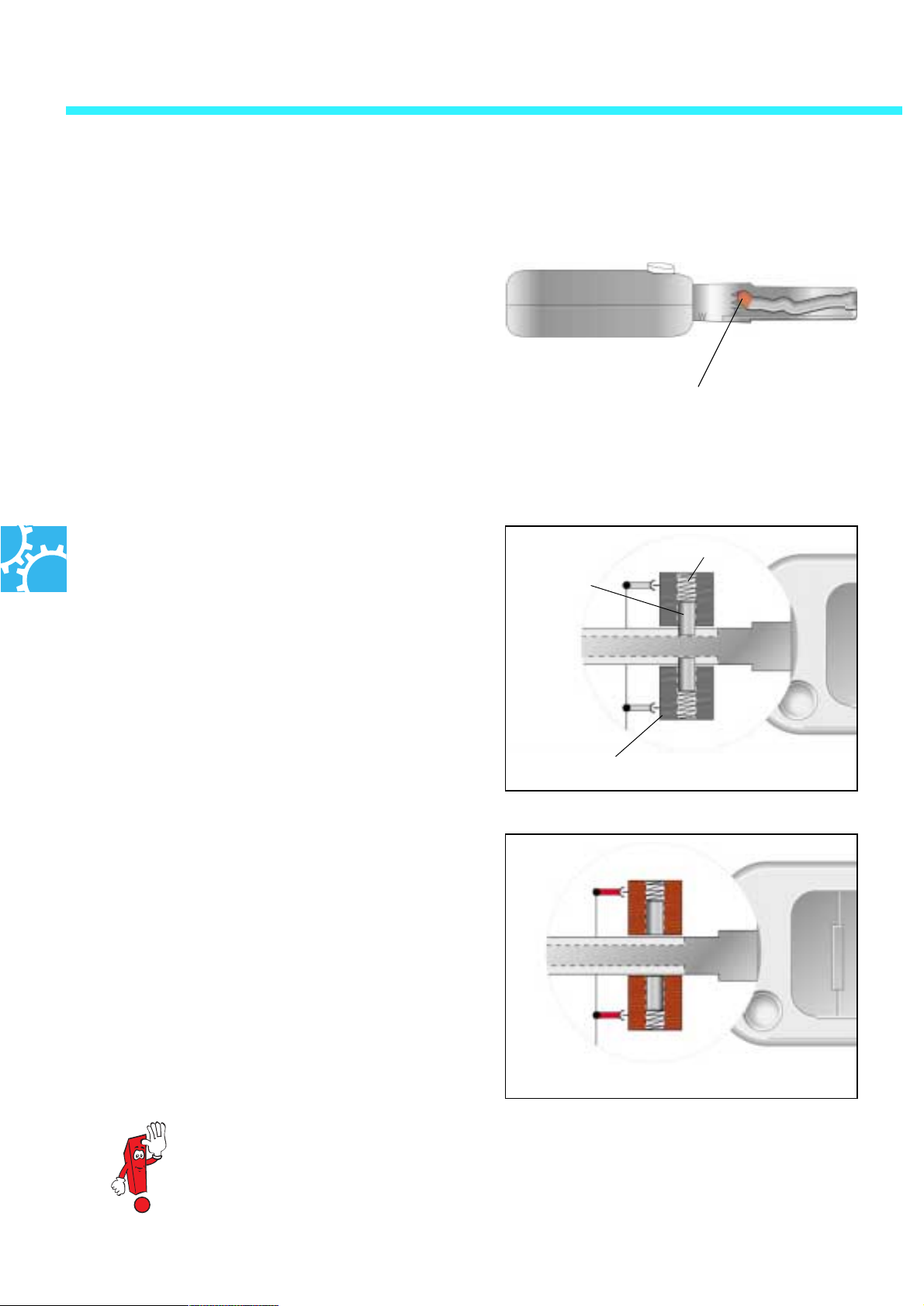
The magnet for ignition key pull-out lock N376
It is located within the switch for access and start
authorisation E415 and prevents the ignition key
from being removed when the selector lever is in
a driving position. Compared with the previous
mechanical systems (by cable control), the ignition key pull-out lock in the Phaeton operates on
an electromechanical basis.
270_111
Extended inside tract
How it works
The ignition lock contains two spring-loaded
locking pins which engage in the extended inside
tract of the inserted ignition key.
The locking pins engage in the extended inside
tract of the ignition key if the selector lever is not
in 'P' position. The ignition key cannot be withdrawn.
When the selector lever is in 'P' position, a signal
travels from the switch for selector lever in 'P'
F319 to the access and start authorisation relay
J518. The control unit then sends current to the
magnet for the ignition key pull-out lock. The
locking pins are pulled out by the magnets and
thus removed from the extended inside tract of
the ignition key. The ignition key can be withdrawn.
Without current
Spring
Locking pins
Magnet for ignition key pull-out lock N334
270_152
Under current
J518
46
270_153
If the vehicle is equipped with a Start/Stop button, the driver receives a visual and acoustic
warning upon leaving the vehicle if the selector lever is not in the 'P' position.
Page 47
Electrical circuitry
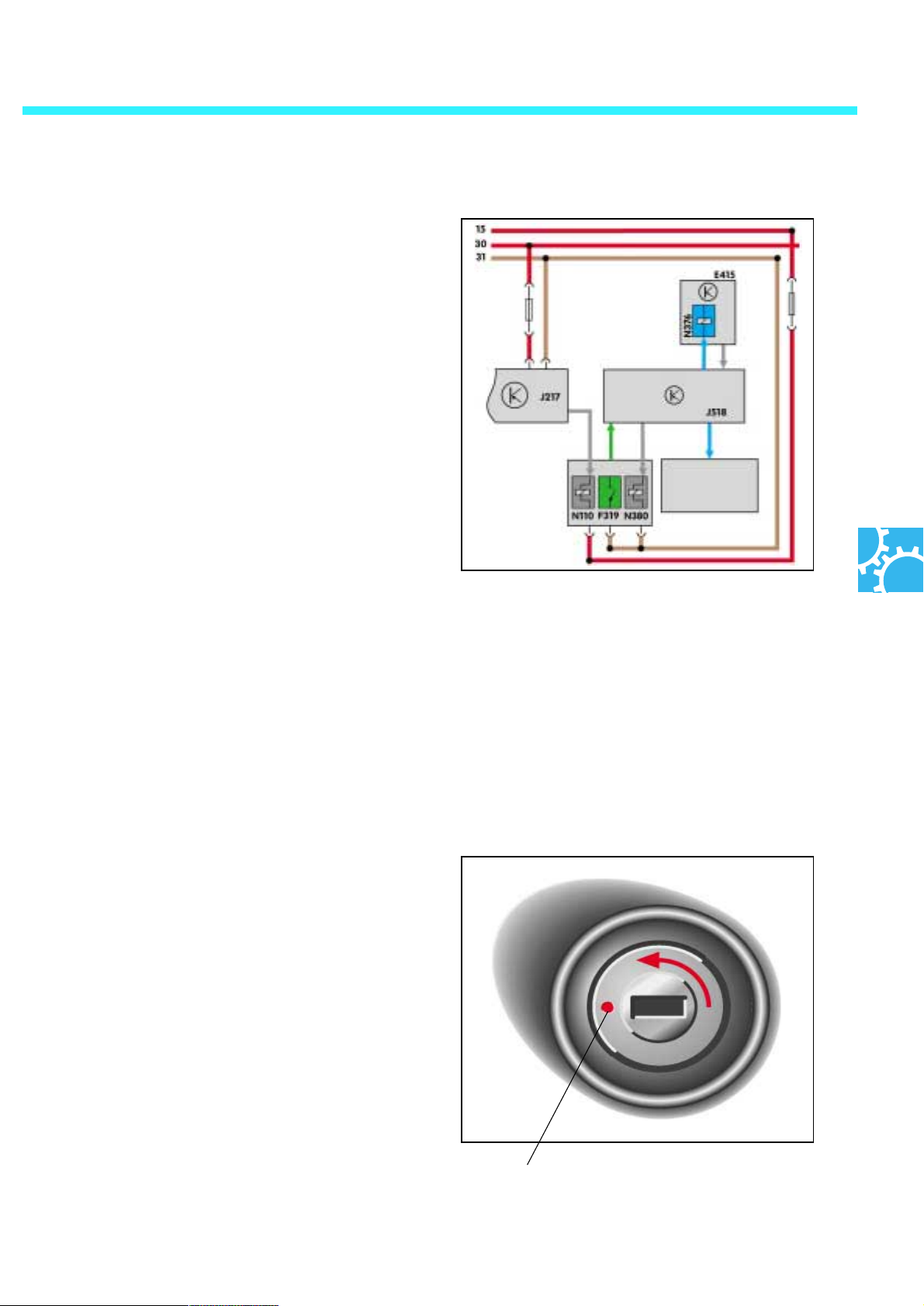
If the ignition is switched off and the selector
lever is in 'P' position, a signal travels from the
switch F319 to the access and start authorisation
relay J518. The control unit then sends current to
the magnets for the ignition key pull-out lock
N376 and the locking pins are released. The ignition key can be withdrawn.
In vehicles with a Start/Stop button, the control
unit signals to the dash panel insert that the
selector lever is not in 'P' position. The control unit
for the dash panel insert then triggers a visual
and acoustic warning. The driver is thus informed
that the selector lever is not in 'P' position.
'Selector lever in P' signal
Dash panel insert
270_226
Effects of drop-out
The electromechanical lock cannot be released
and the key cannot be withdrawn if the signal
from the selector lever to the control unit J 518 or
the signal from the control unit to the ignition lock
fails. In these circumstances, the ignition lock has
an emergency release for the ignition key.
Emergency release
Press the emergency release button with a pen or
similar object. While keeping the button pressed,
then turn the ignition key to the left and remove
it.
270_110
Emergency release
47
Page 48
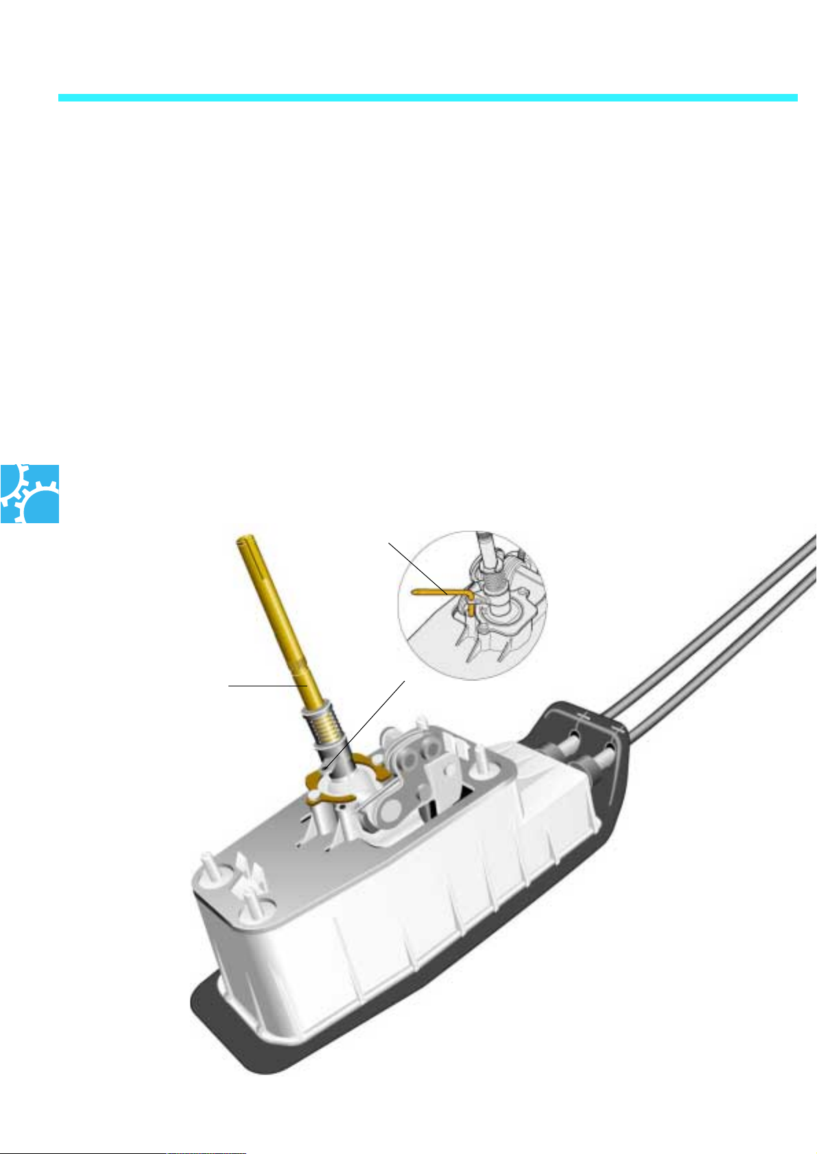
Manual gearbox
The 6-speed manual gearbox FWJ
The 6-speed manual gearbox has already
proven itself as the basic gearbox for the frontwheel and four-wheel drives in the engines longitudinal mounting.
In the Phaeton, it is deployed as the front-wheel
drive gearbox in conjunction with the V6 engine.
In order to maximise convenience of use, actuation by means of a control cable is used instead
of a linkage gearshift. An appropriate support
has been specially developed on the gearbox
housing for the control cable mounting and for
the actuation of the shifter shaft in the gearbox.
Adjustment drift T10027
The ends of the cable are attached with locknuts
to the steering levers. Mass dampers support the
shifting movements and absorb vibrations.
In order to adjust the control cables, the gearshift lever is locked in place in the left neutral
position by the adjustment drift T10027 when the
shift cables are loosened.
A stopping drift is located on the bearing housing of the shifter shaft end on the gearbox housing. This is turned to the right in order to secure
the shifter shaft in the left neutral position. The
cable ends can now be attached again.
Gear-shift lever
270_219
270_175
48
Page 49
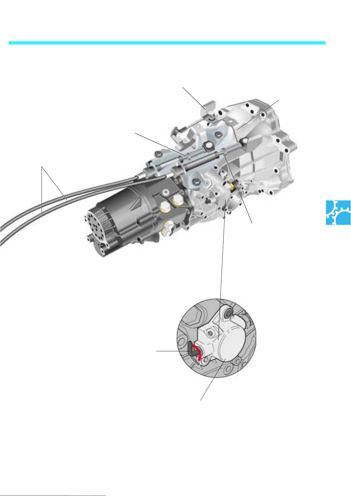
Shift cable
Mass damper
Steering lever
Locknut
Locknut
270_176
Stopping drift
270_218
Shifter shaft bearing housing
49
Page 50
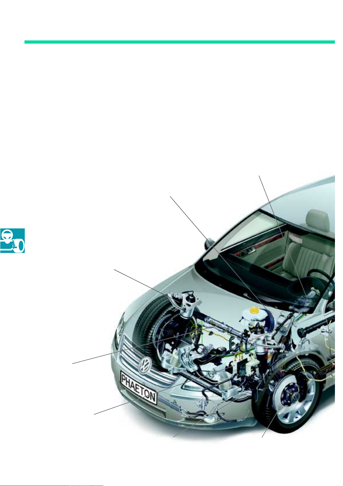
Chassis
The chassis in the Phaeton
The chassis with front-wheel and 4-motion drive
is combined with a 4-corner air suspension. This
facilitates an extremely sensitive activation of the
suspension even on slightly uneven driving surfaces.
Electrically adjustable steering column
with electrical steering column locking
Tandem brake servo
4-corner air suspension with
Servotronic as standard
Bosch 5.7 with ESP and
braking assistant
regulated attenuation
Four-link front suspension
270_089
Assembled brake discs with
8-piston brake calliper
50
Page 51
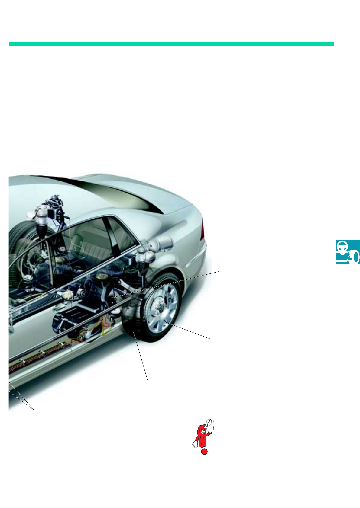
Tyres, extra-load design
Foot parking brake with mechanical
loosening device in the dash panel
Trapezoidal wishbone rear suspension for front-wheel and four-wheel
drive
Alloy wheels
The chassis is described in detail in
SSP 277 “Phaeton - The Chassis”.
270_090
51
Page 52

Convenience electronics
The memory functions
The vehicle offers a large variety of memory functions which are saved and accessed via various operating panels. In addition to the functions controlled via the seat memory, user settings can be created using
the ignition key with radio-wave remote control.
These user profiles communicate via the main information display and operating unit and the access
and start authorisation relay.
Seat memory
Component Storable components/functions
Driver's seat Seat settings: Longitudinal adjustment, inclination adjustment, backrest inclination,
height adjustment, legrest adjustment, backrest head adjustment, headrest adjustment, vertical and horizontal lumbar support, outside mirror, remote control,
steering column (height and length adjustment), seatbelt height and interior mirror
Front passenger seat Seat settings: Longitudinal adjustment, inclination adjustment, backrest inclination,
height adjustment, legrest adjustment, backrest head adjustment,
headrest adjustment, vertical and horizontal lumbar support, seatbelt height
Rear seats (left / right) Seat settings: Longitudinal adjustment, inclination adjustment, vertical and
horizontal lumbar support, headrest
Main information display and operating unit
Component Storable components/functions
Air-conditioning system Air-conditioning functions right / left, front / back, air recirculation automatic
operation, solar ventilation and weekly timer for auxiliary heater
Tele p hone Activating the telephone functions: caller display
Navigation Display (map / symbol), route options, announcements (on / off), traffic jam alert
Audio - TV Preselection of radio station, CD, TV and volume, GALA, sound settings
Settings Units of measurement, volume, system language and settings for
orientation illumination (fade-out time)
Vehicl e Tyre pressure control, spare tyre monitoring
52
Board PC Choice of representation (from start, until destination, long-term)
Page 53
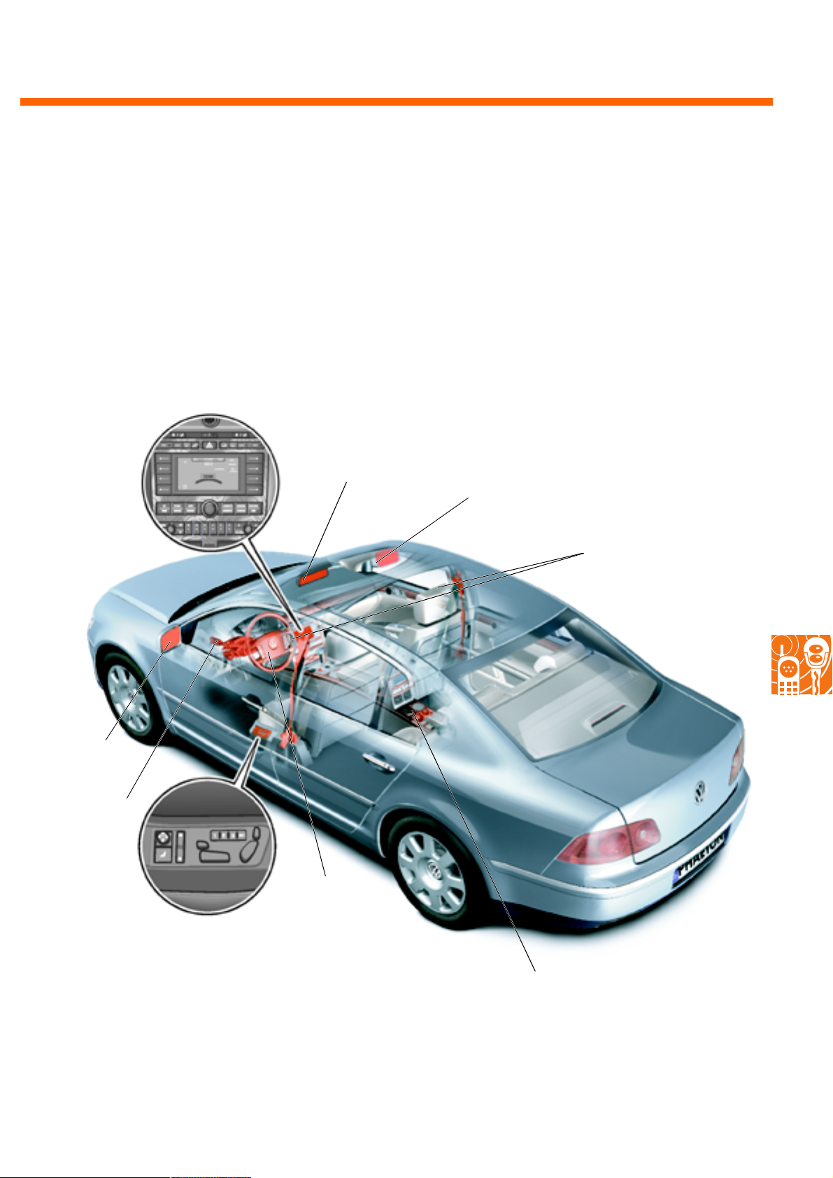
The graphic below provides an overview of the controls and their associated memory function components. Please consult the appropriate chapters for a more precise description of the main information
display and operating unit controls and for information regarding seat adjustments.
Overview of memory components
Main information display and operating unit at the front
Interior mirror
External mirror
Belt height adjustment
External mirror
Steering
column
Seat memory
control panel
Multifunctional
steering wheel
Memory control panel at the rear
270_208
53
Page 54

Convenience electronics
The access and start authorisation system
The vehicle can be locked or unlocked and the engine can be started or switched off, without the active
deployment of the radio-wave remote control ignition key, by using the optional comfort features of the
access and start authorisation system.
The components and functions listed in the table are constituent parts of the access and start authorisation system.
Ignition key with radiowave remote control
Electromechanical
steering column locking
(ELV)
Switch for access and
start authorisation
Immobiliser III Immobiliser III as before, acting together with the switch for access and start
Softstart Via the CAN data bus drive and the access and start authorisation relay; also for
Fitting positions for
access and start authorisation components
Radio-wave remote control as before, the access and start authorisation relay
analyses the radio signals; central locking functions via the
central control unit for the convenience system; tailgate remote control
Locking and unlocking of the steering column when inserting and removing the key
by the access and start authorisation relay, ELV is off-circuit as long as the key is
neither removed nor inserted, ignition can be activated only when the steering
column is unlocked
Automatic resetting of the ignition key to the neutral position after switching on the
engine, electrical pull-out lock: each key mechanically fits into the switch for access
and start authorisation and can be rotated; ignition occurs only once the ignition
key has been identified by the access and start authorisation relay
authorisation, the engine control unit and the ELV
prolonged stops in the starting position (terminal 50 on), in the switch for access
and start authorisation the starter is engaged only until the engine is running leading to improved starter protection and less noise
Access and start authorisation relay: left footwell under the carpet
Switch for access and start authorisation: on the right of the steering wheel
Electromechanical steering column locking: steering column
Rear antennae: bumpers
Shift-shaft antenna: shift-shaft covering panel
Tunnel antenna: rear tunnel on the cable channel
Central armrest antenna: rear seat central armrest / ski-bag cover
Hat rack antenna: modular hat rack
Button for access and start authorisation: shift-shaft covering panel
Electronic door handles: external door handles
54
Please consult self-study programme 273 “The Phaeton - Convenience and Safety Electronics” for further information on “Access and start authorisation”.
Page 55
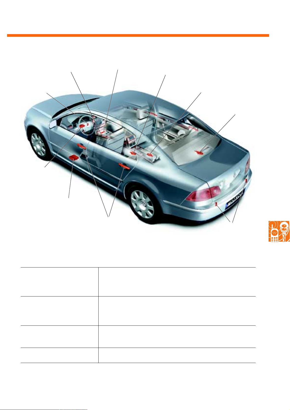
Convenience electronics
Button for access and
start authorisation
Switch for access and
start authorisation
Electromechanical
steering column
locking
Shift-shaft
antenna
Tunnel antenna
Central
armrest antenna
Hat rack
antenna
Access and start
authorisation relay
Electronic door
handles
Additional functions of the comfort features for access and start authorisation
Vehicle access without active
deployment of the ignition key
Starting the engine without
active deployment of the
ignition key
Turning off the engine
without active deployment of the
ignition key
Opening with radio-wave remote control using antenna and sensor in the
external door handle, key identification by the access and start authorisation relay, unlocking via central control unit for the convenience system
and door control unit
Ignition key check in the vehicle interior via interior antennae, starting the
engine with the button for access and start authorisation, unlocking the
steering column with the access and start authorisation relay once ignition
key has been positively identified
Pressing the button for access and start authorisation
Rear antennae
270_209
Vehicle locking without active
deployment of the ignition key
Pressing the locking button in the external door handle
55
Page 56
Electrics
Automatic distance control (ADC)
ADC is a driver-assistance system which enhances cruise control.
By reducing motor torque and the possible application of the brake, an ADC-vehicle is kept at a convenient distance behind a slower-moving vehicle in front.
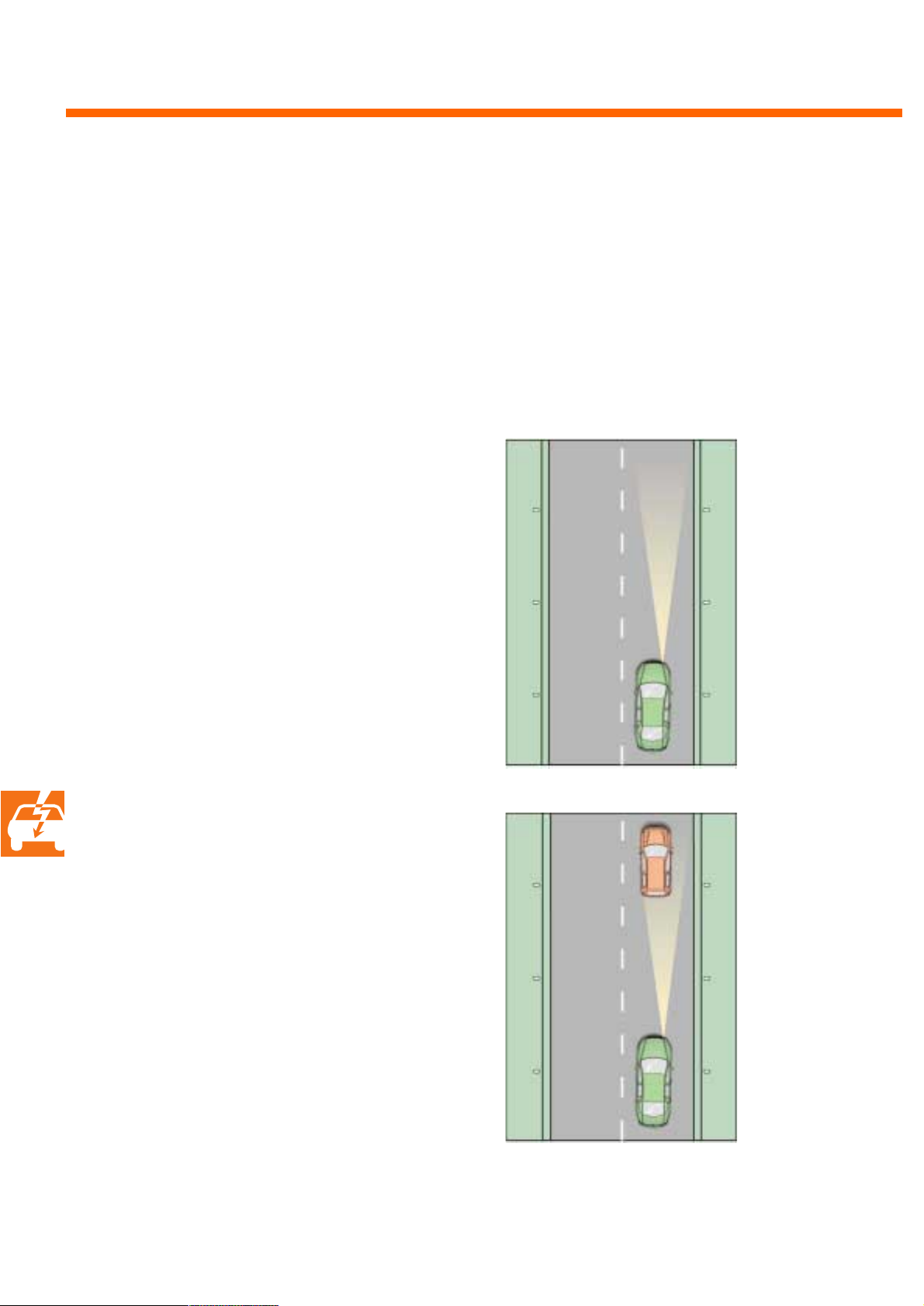
Its function is clarified by the four traffic scenarios presented below.
Steady speed
There are no vehicles driving ahead within the
distance-regulator sensor's detection area. The
driver's desired speed is maintained.
Delay
When the ADC-vehicle approaches a slowermoving vehicle, speed is slackened by reducing
the engine torque and, if necessary, through a
moderate application of the brake. The driver is
prompted to take over the braking operation if
the delay is insufficient.
100 km/h
270_197
80 km/h
100 km/h
→ 80 km/h
270_198
56
Page 57
Effects
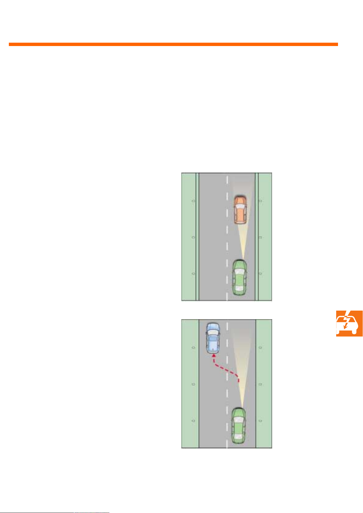
The ADC-vehicle adapts itself to the speed of the
vehicle in front.
Acceleration
80 km/h
80 km/h
270_199
The ADC-vehicle accelerates to the desired
speed once the vehicle in front leaves the traffic
lane or the detection area.
80 km/h
80 km/h
→ 100 km/h
270_200
57
Page 58
Electrics
Conditions for switching on and off the ADC
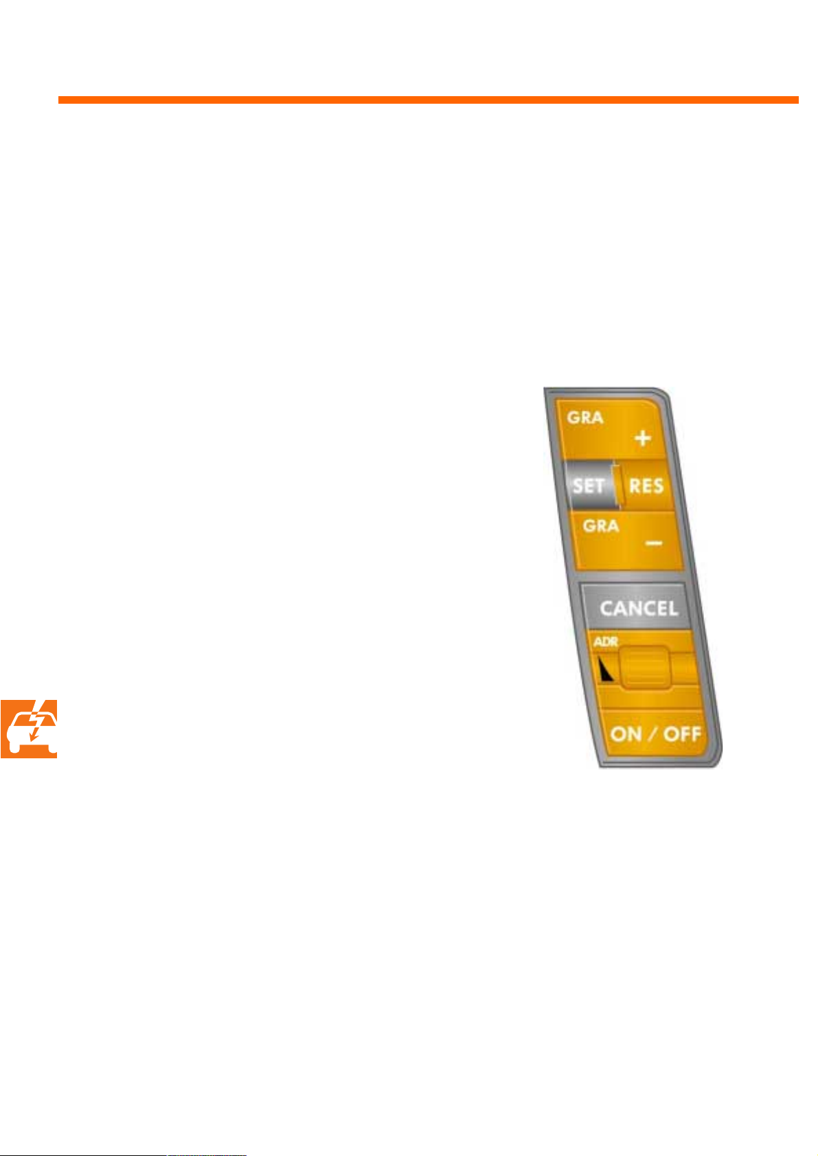
ADC system status is influenced by the left bank of buttons on the multifunctional steering wheel, the
accelerator, the brake pedal, the selector lever, as well as by the engagement of the vehicle's built-in
braking system.
The ADC system is always in a 'non-ready state' when the engine is started and has to be switched to
stand-by by pressing the ON/OFF key.
Switching on
The ADC system can be switched on at a driving
speed of between 30 and 180 km/h.
The keys have the following functions:
- The SET key adopts the current speed
as the desired speed. Repeated pressing
reduces the desired speed by 1 km/h each time.
- The RES key adopts the previous desired speed.
Repeated pressing increases the desired
speed by 1 km/h each time.
- The +GRA key or the -GRA key increases
or reduces the desired speed in increments of
10 km/h.
Switching off
- ON/OFF key, desired speed is lost
- CANCEL key, desired speed is maintained
- Stepping on the brake pedal
- Excessive application of the accelerator
- Selector lever in P, R, N
- Driving speed outside of the range
of 30 to 180 km/h
- Application of ESP, ASR, MSR, ABS
270_201
58
Page 59
New components
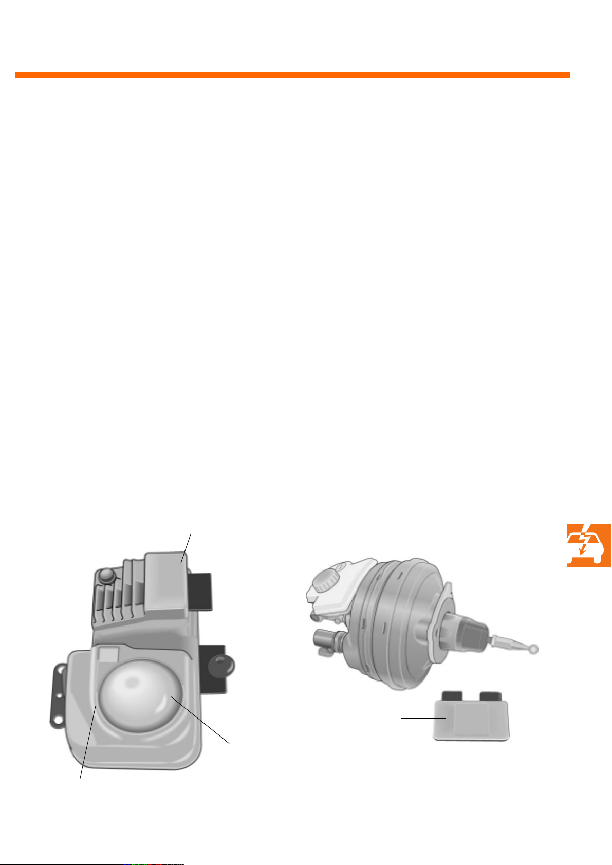
The ADC function is made possible by the deployment of a distance sender in accordance with the radar
principle and by an active electronic brake servo.
Important data regarding the distance control sender include:
Transmit frequency: 76.5 GHz
Visual range: 150 m
Horizontal viewing angle: 12 °
Vertical viewing angle: 4 °
Speed measuring range: ± 180 km/h
Computer part
The electronic brake servo is a well-known tandem amplifier in which an integrated electromagnet controls the pressure distribution in such
a manner that approx. 30% of the braking force
can be activated electrically.
The necessary braking convenience is ensured by
a brake pressure control with a separate sender
for brake pressure and a membrane position
control with a separate membrane position
sender.
The electronics associated with the amplifier are
accommodated in the control unit for braking
force amplification.
mm-wave section
Lens
Control unit for
braking force
amplification
270_196
270_195
59
Page 60
Electrics
Headlights
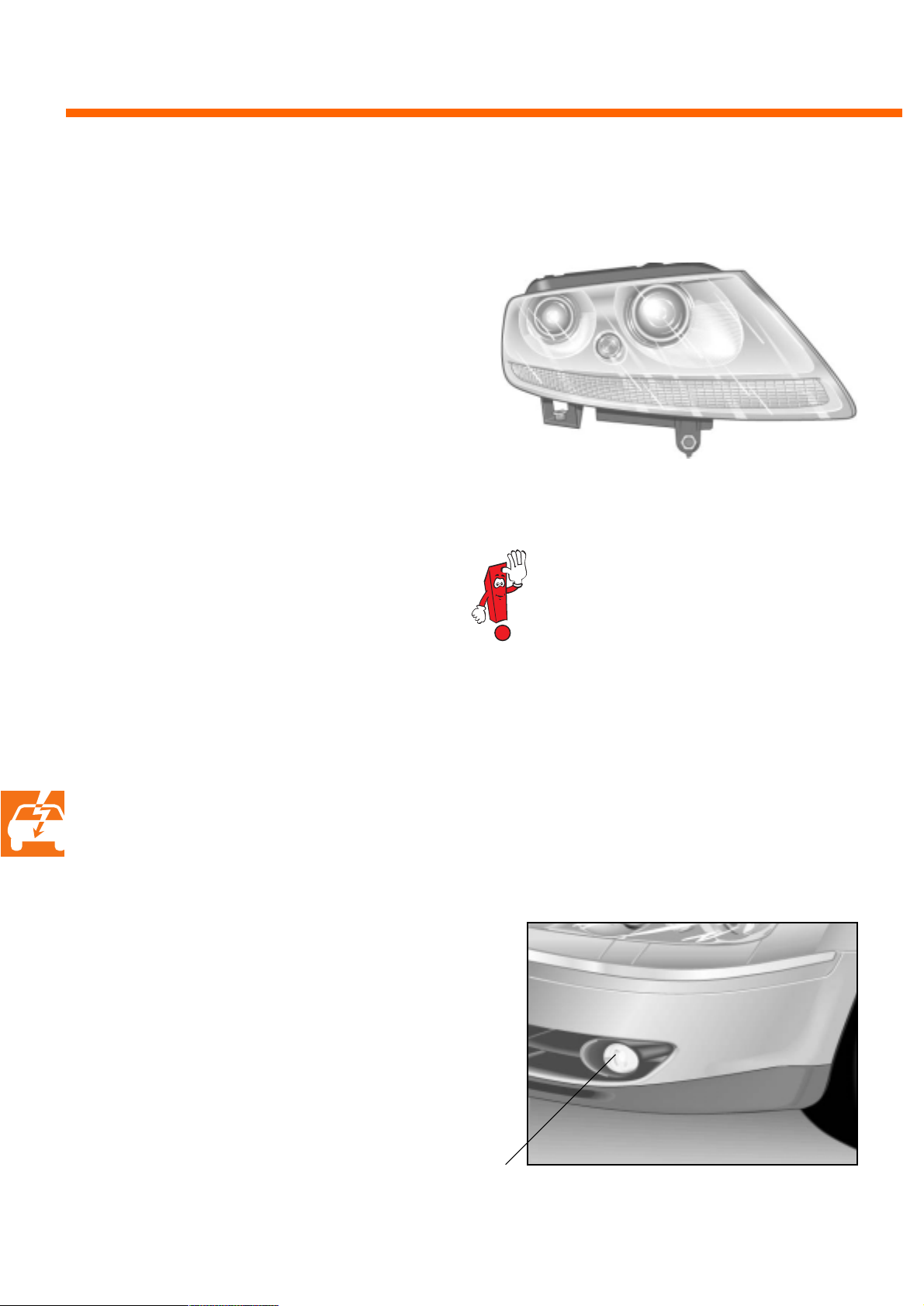
Various headlight designs are available. The
basic equipment consists of an xenon headlight
with gas discharge lamps for the dipped beam
and a HB 3 lamp for the high beam.
Double xenon headlights are available as an
optional extra with the V6 engine or W12 engine
series. With this system the dipped beam and
high beam light is generated by gas discharge
lamps.
A gas discharge lamp for high beam is also
turned on when switching from dipped beam to
high beam light.
The indicator lights are integrated in the headlight; the H21W bulb is not visible under the covering.
This makes possible a level of homogeneity
which is unique for such unusual dimensions.
Fog lights
270_237
The gas discharge headlights are diagnosis-capable via the VAS 5051 measuring
and diagnostic system.
60
The fog lights are built into the bumper. They are
based on reflection technology with a H11 lamp
and a transparent cover disk.
Fog lights
270_238
Page 61
Rear lights
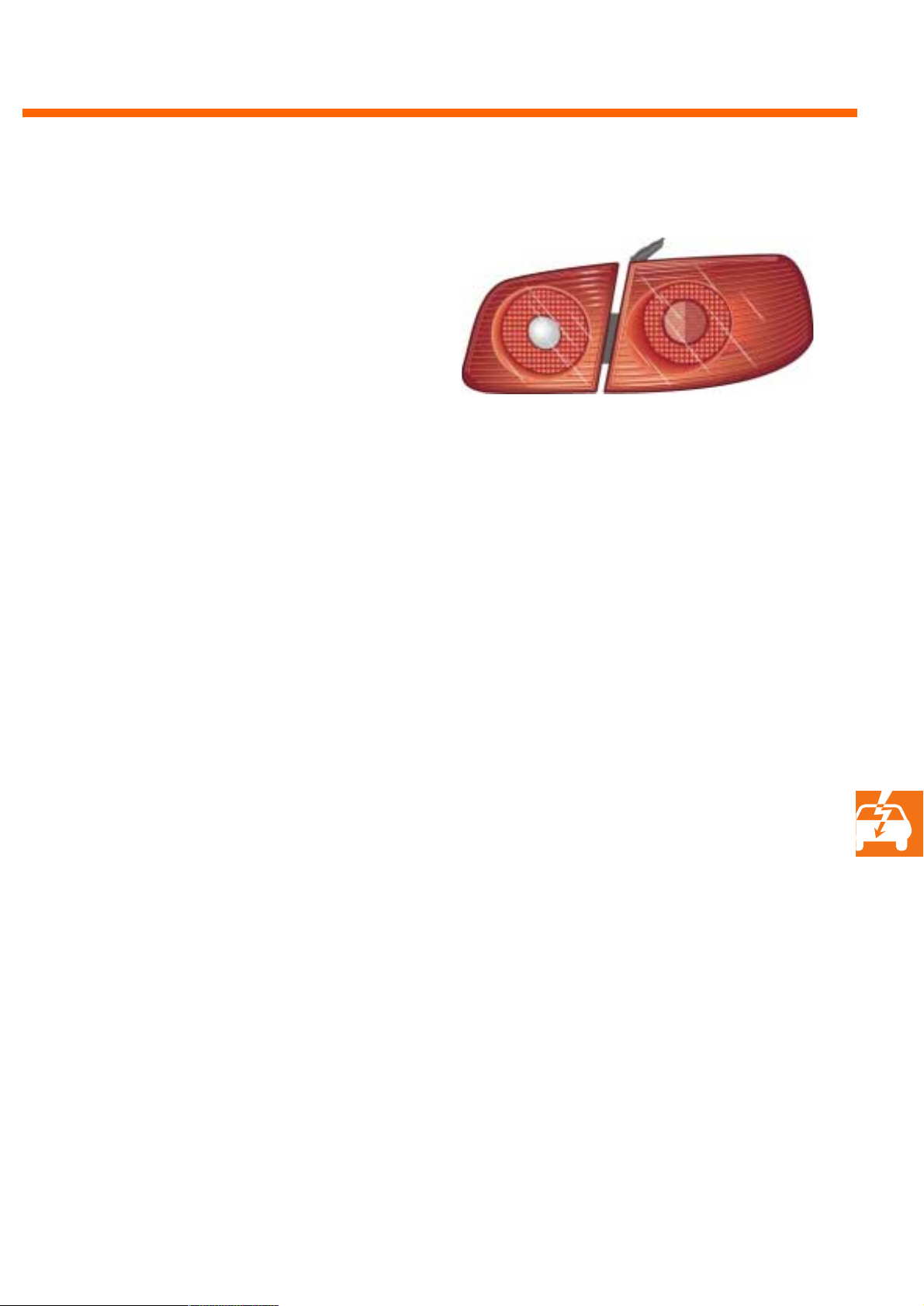
The rear lights are designed with light-emitting
diodes (LED). Lower energy consumption, shorter
response times and a longer service life are
among the advantages.
A malfunction is detected in the event of the LEDs
becoming defective. The driver receives notification of the problem in the dash panel insert.
270_236
Brake light
Red glass with rear fog lights
26 LEDs 13.5 V 5.7 W
Without rear fog lights
90 LEDs 13.5 V 13 W
Rear fog lights
Red glass
48 LEDs 13.5 V 9.7 W
Rear light
Red glass
123 LEDs 13.5 V 1.8 W
90 red LEDs 33 red/yellow LEDs
Direction indicator
Red glass
33 LEDs 13.5 V 8.9 W
Reversing lights
Clear glass
Bulb HPL 13.5 V 16 W
61
Page 62
Electrics
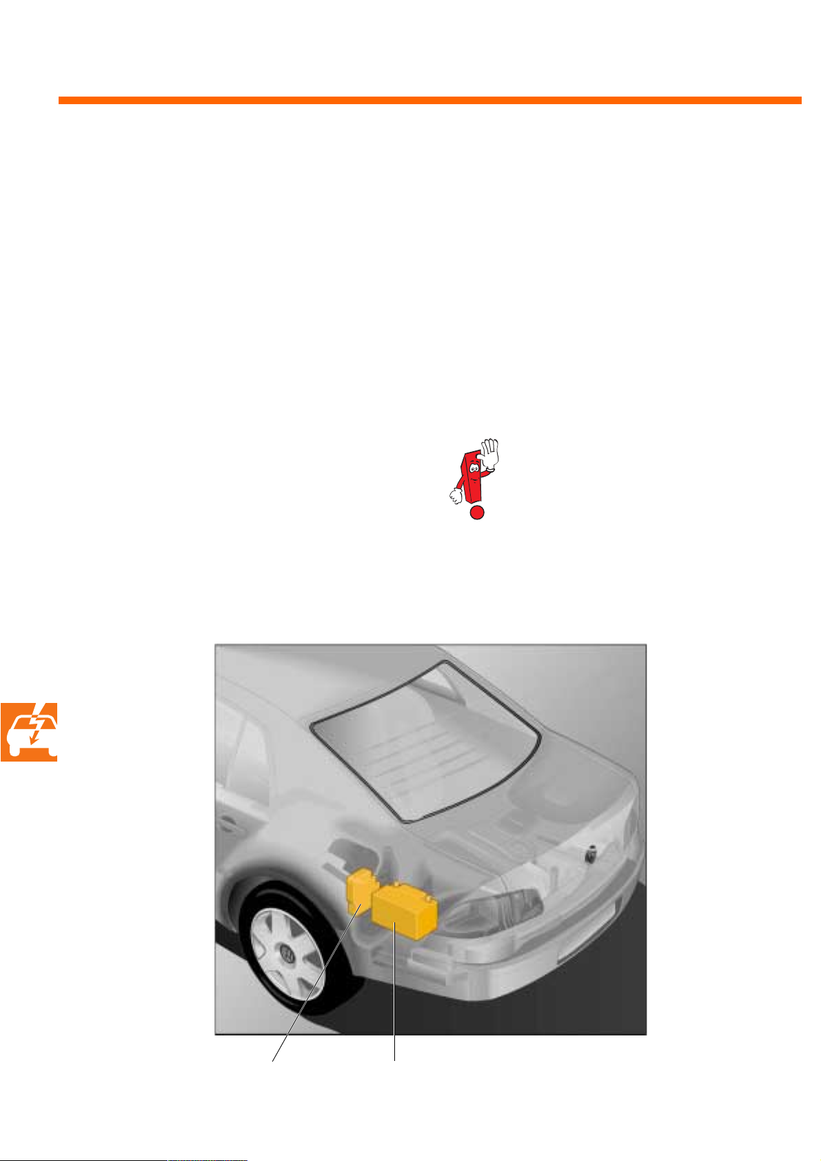
Battery design
The battery has the task of guaranteeing the
electrical energy for starting the engine and of
feeding the electrical consumer units. One battery is not sufficient for fulfilling this requirement
in all models.
In order to ensure a sufficient energy supply for
the electrical consumer units and the starter, a
● one-battery on-board network
and a
● two-battery on-board network are deployed.
One-battery on-board network
Vehic l es with
● V 6 engines
are fitted with one battery.
The electrical consumer units are supplied by one
battery in all operating conditions.
The repair instructions on the subject of
battery removal and installation are to
be observed in order to avoid malfunctions in some electrical components
after a complete voltage failure.
62
270_232
BatterySeries fuse box
Page 63
Two-battery on-board network
Vehic l es with
● W 12 and
● V 10 TDI engines
Additional feature for vehicles with
● V 6 engines
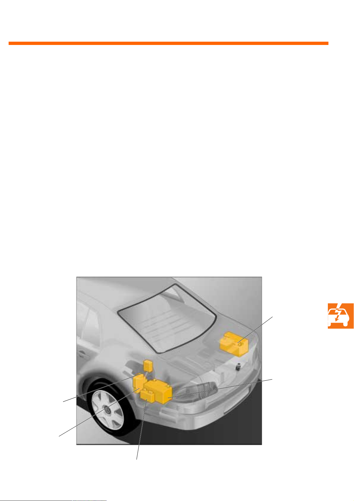
The two-battery on-board network consists of a
starter battery, an on-board network battery, a
relay for parallel wiring battery (J581) and a battery monitor control unit (J367).
The starter battery feeds the starting current circuit for starting the engine; the on-board network
battery feeds the 12V on-board network.
Starting with a discharged on-board network or
starter battery is possible. Control is effected via
the battery monitor control unit and the relay for
parallel wiring battery.
Both batteries are wired in parallel at temperatures below 0°C in order to satisfy the cold start
requirements of the V10 TDI engine.
Relay for parallel
wiring battery
Series fuse box
Starter battery
On-board
network battery
270_231
Battery monitor control unit
63
Page 64
Electrics
Jump-start
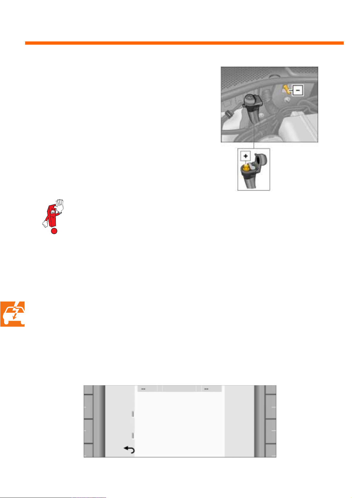
Starting with an external voltage source is possible if the battery in a one-battery on-board network is discharged or both batteries in a twobattery on-board network are discharged. The
voltage source may only be attached to the
starter side terminal 30a at the jump-start connection.
This method only supplies consumer units relevant to the starting procedure and protects the
on-board network.
270_230
Please observe the safety instructions in the workshop and operating manuals.
Adjusting headlights
The headlights have to be locked in place in the
'basic setting' function prior to adjustment with
the measuring and diagnostic system 5051.
Mechanical access to the headlight adjustment is
opened via the control unit for front information
display and operating unit (J523).
Changing the wiper blades
To change the wiper blades, they first have to be
moved into the service position via the control
unit for front information display and operating
unit, 'Maintenance & Service' function.
The service position can only be reached by
observing particular preconditions. Please
observe the instructions in the applicable workshop manuals.
64
Wiper
change
Head-
lights
Back
°C PROJECT TP °C
Other/Maintenance & Service
Moves the wiper blades to the
Opens the mechanical access to
SETTINGS
change position.
headlight adjustment.
270_235
Page 65
Battery
Plate group
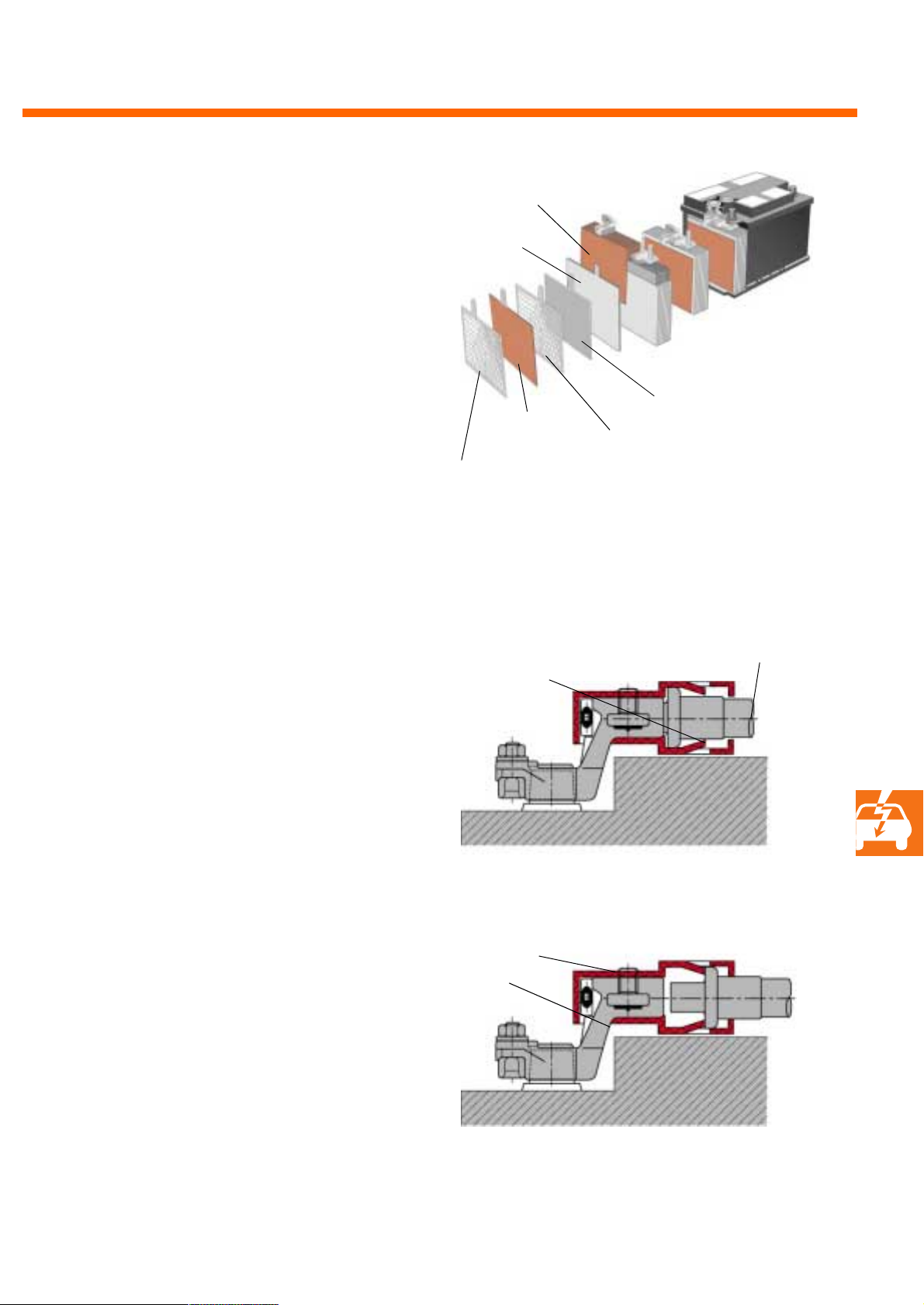
The on-board network battery is maintenancefree due to the use of non-woven fabrics containing latent sulphuric acid. The cells' fill plugs cannot be opened. The emerging gases are fed into
the wheel housing via a lateral outlet and a supply pipe.
Safety battery terminal
In the event of a crash, the starter battery's battery lead is separated pyrotechnically from the
battery. The trigger thresholds are dependent on
the gravity of the accident and on the direction
of impact and they are stored in the airbag control unit.
Fabric
Positive plate
Positive grid
Non-triggered system
Press-fitted cone pin
Negative plate
Negative grid
272_240
B+ lead to the starter
Trigger ed sys tem
Plastic clip-on cover
B+ terminal
270_233
65
Page 66
Heating/air-conditioning system
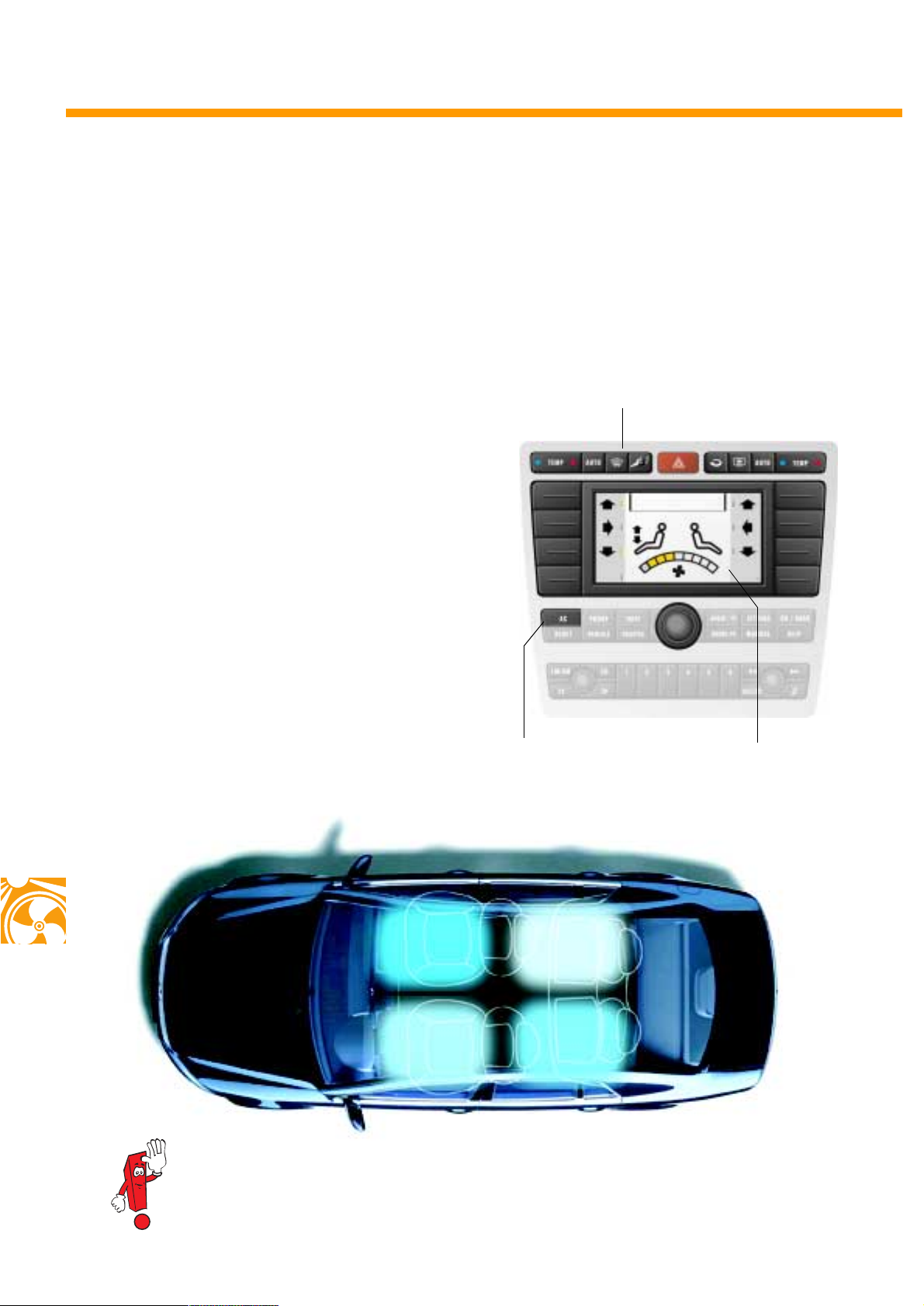
The 4C Climatronic
As a luxury-class saloon, the Phaeton has a fourzone air-conditioning system as standard. Thanks
to the 4C Climatronic (4 corners), both the driver
and passengers can enjoy their own desired airconditioning settings independently of each
other. The temperature range available is
between 18 °C and 28 °C.
The air-conditioning system is controlled via the
Infotainment with the air-conditioning row and
the 'AC' main-menu button.
Pressing this button calls up the main air-conditioning menu on the Infotainment's display.
Air-conditioning row
270_210
'AC' main-menu button Main air-conditioning
menu
66
24° C
18° C
23° C
22° C
270_103
More comprehensive and detailed information on the heating and air-conditioning system
can be found in self-study programme 271.
Page 67
Special functions
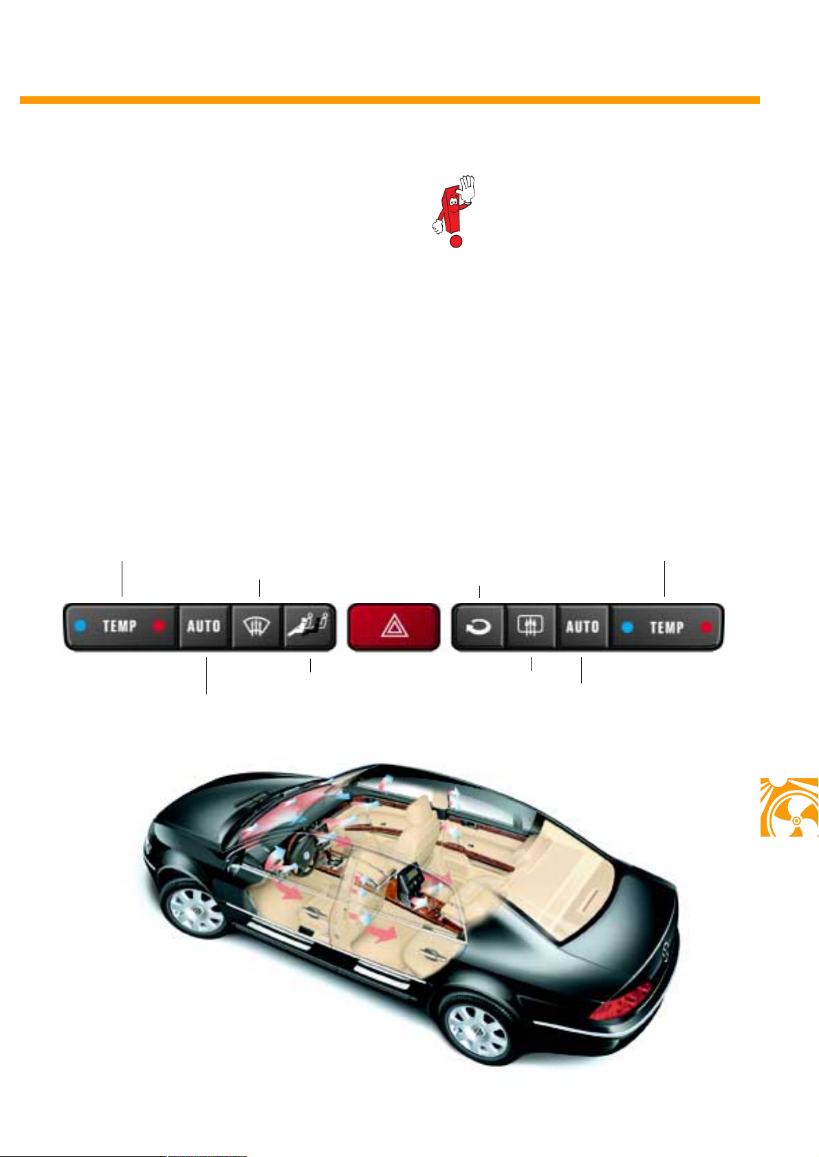
● Automatic and manual air-conditioning
control for each air-conditioner zone
● Air-conditioner synchronisation:
all air-conditioner zones will be tuned to the
settings of the driver's seat
● ECON function
● Automatic and manual recirculating air
function with air-quality monitoring
● Automatic and manual defrost function
with window-mist recognition
● Provision for direct sunlight
during climatic regulation
Driver temperature
Manual defrost function
If the Phaeton is equipped with the
optional extra of an electrical windscreen heating, this will also be
switched on or off via the button for
manual defrost.
Front-passenger temperature
Manual recirculating air function
Air-conditioner synchronisation
Automatic climatic regulation,
driver-side
270_217
Rear window heater
Automatic climatic regulation,
front-passenger-side
270_174
67
Page 68
Heating/air-conditioning system
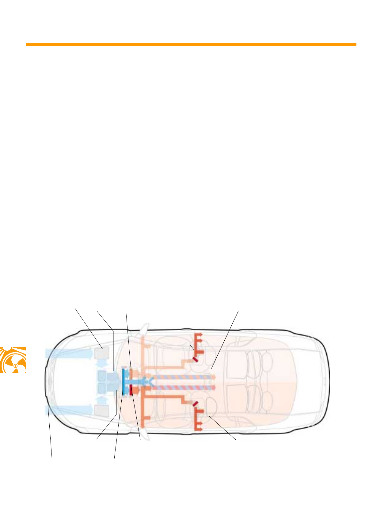
Air distribution in the vehicle
The blower sucks in fresh air through the dust
and pollen filter and conducts it to the vaporiser.
The airflow in the air-conditioning device is separated for the first time behind the vaporiser:
the main part flows through the heat exchangers
and a smaller part bypasses the heat exchangers
and is fed to the air flaps in the air-conditioning
device.
Its structural design with two adjacent heat
exchangers results in a right-left distribution for
the ventilation of the vehicle's interior.
The temperature of both of these airflows for the
left and right-half of the vehicle is to a great
extent determined by the temperature settings for
the front seats.
The subsequent division of the air behind the
heat exchangers to the individual air outlets is
effected by electro-mechanical flaps on the airconditioning device and in the dash panel.
In doing so, the air for the outlets in the B-pillars
and for the rear footwell air outlets can be
heated further with additional heating elements.
Dust and pollen
filter Right heat exchanger
Fresh air
Air-conditioning
device
Vapo ri se r
Left heat exchanger
Additional heating elementFresh air blower
Centre console air outlet
270_239
Footwell air outlet and outlet for defrost and
direct ventilation in the B-pillar
68
Page 69
The structural features
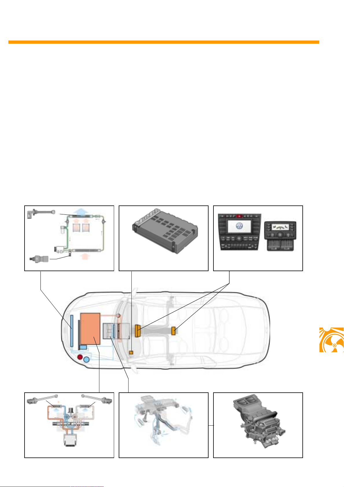
The heating/air-conditioning system can be subdivided into the following categories:
- Cooling circuit
with the sender for coolant pressure and temperature G395 and the temperature sensor
vaporiser G308,
-Heating circuit
with pump valve unit, two independent heat
exchangers regulated on the water-side, as
well as the two temperature sensor heat
exchangers G306 left and G307 right,
G395
G308
Cooling circuit
- Sub-assemblies for air distribution with an
air-conditioning device for realising the four
air-conditioner zones,
- Display and operating units at front and back,
- Climatronic control unit.
Climatronic control unit
Display and operating units
270_211 270_159 270_189
G307 G306
270_208
Heating circuit
Air duct
Air-conditioning device
270_185270_216270_212
69
Page 70
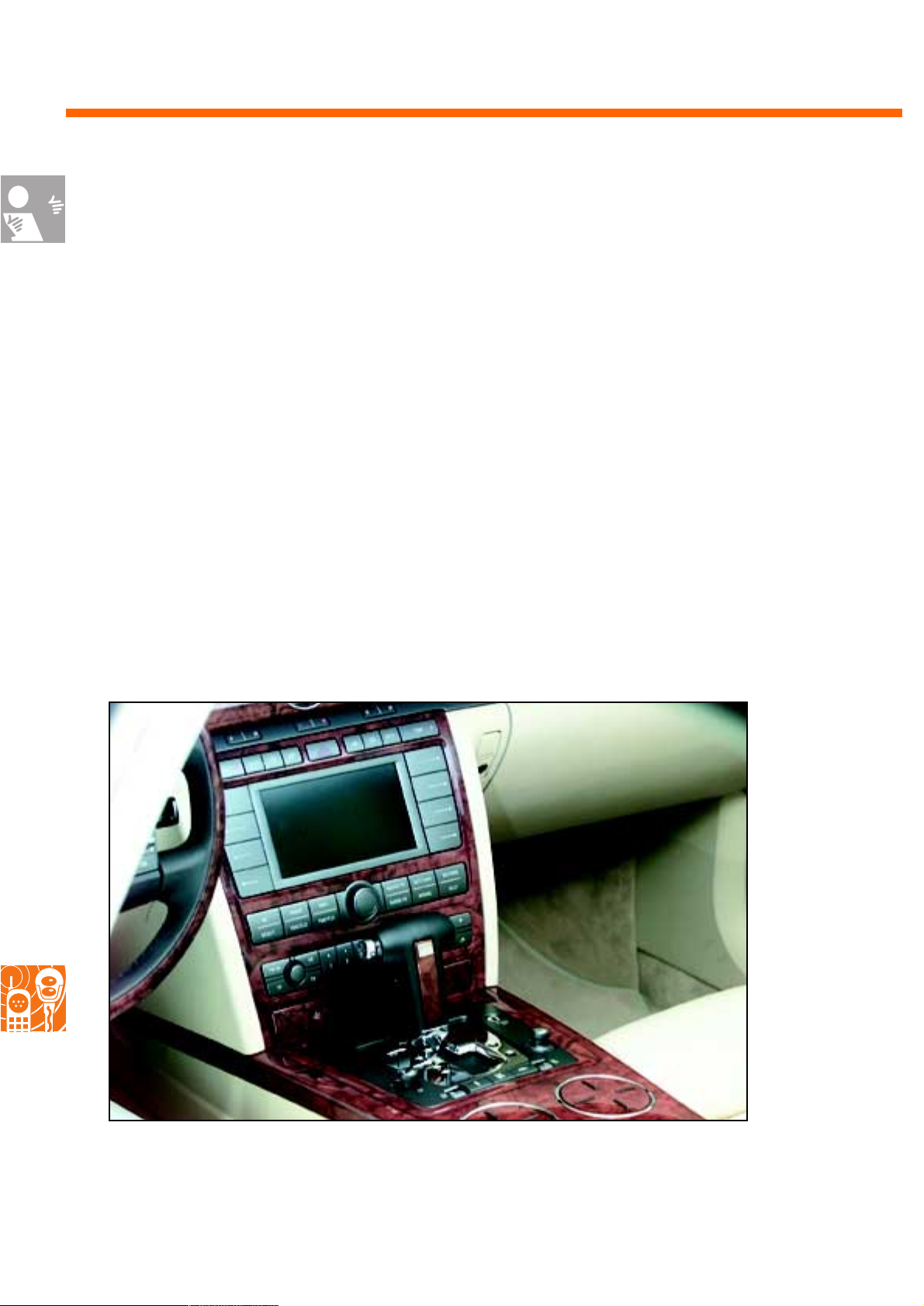
Infotainment
The Infotainment system
The Phaeton Infotainment system supervises a range of functions which can be controlled via the operating units in the dash panel and on the steering wheel and by a Climatronic display and operating unit at
the back. Please consult SSP 274 for more detailed information on the Phaeton Infotainment.
Infotainment functions are:
- Audio (AUDIO/TV)
(Radio, CD player, Television),
- Tel eph on e (PHONE)
(Mobile phone, Address-book management),
- Navigation (NAVI)
(Destination guiding, Destination information),
- Tel eme tr y (TRAFFIC)
(Traffic jam alert, Alternative routes),
- Travel data (BOARD-PC)
(Distance data, Consumption, Fuel stop),
Infotainment cockpit operating unit
- Air conditioner (AC)
(Regulating heating/air-conditioning system,
Solar roof function, Auxiliary heater),
- Setting variations (SETTINGS)
(Wiper blade change, Headlight setting,
Voice control, Service functions)
- Tyre pressure control (VEHICLE) and
- Chassis settings
(Level and shock absorber control).
70
270_086
Page 71
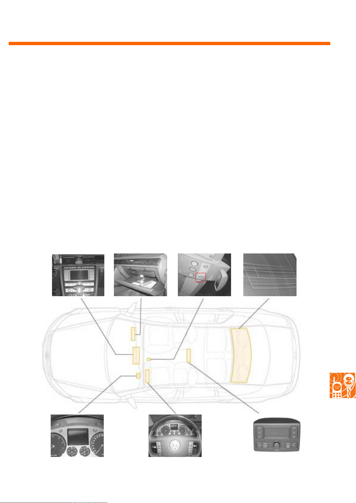
In addition to the operating units in the cockpit,
steering wheel and at the back, the Infotainment
system is essentially composed of:
- the display in the dash panel insert,
- the navigational processor with CD-ROM
and CD player in the glove compartment,
- the antennae in the rear window and
- the microphone for voice control
and telephoning.
The microphone is built into a front console in the
roof lining.
Navigational processor
Display and
operating unit
and CD player in the
glove compartment
These main elements are interlinked in the CAN
data bus Infotainment.
This data bus network is one of a total of three
CAN data bus networks in the Phaeton:
- CAN data bus drive
- CAN data bus convenience and
- CAN data bus Infotainment.
All three networks exchange information with
one another. Infotainment can therefore access a
wide range of sensors and actuators.
Microphone above the
front seats
Antennae in the rear
window
Display in the
dash panel insert
Multi-function
steering wheel
270_074270_073270_071270_072
270_066
270_077270_076270_075
Display and
operating unit, rear
71
Page 72
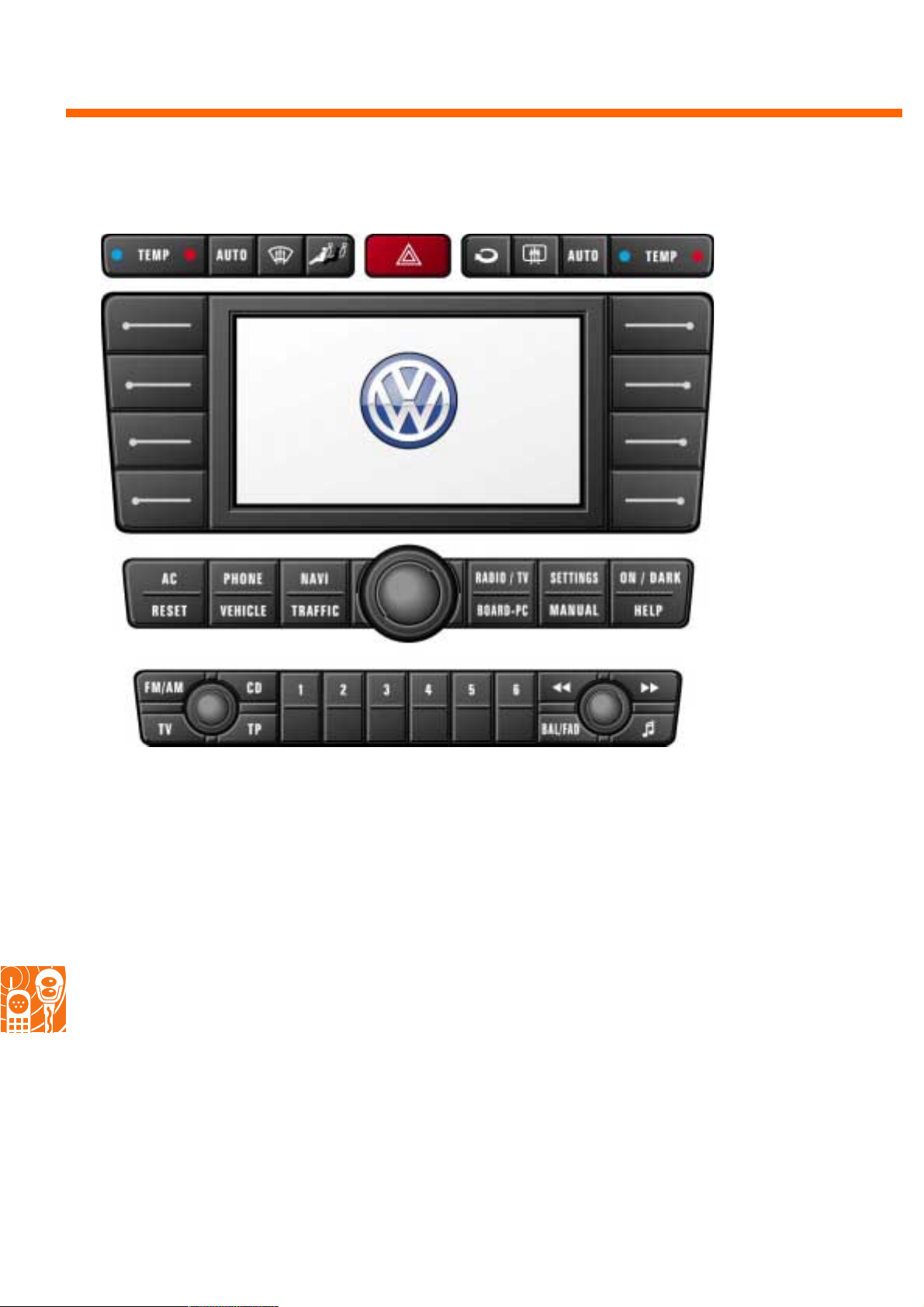
Infotainment
Display and operating unit, front
Air-conditioning row
Function buttons
with display
Welcome
Main menu row
Audio row
270_068
The display and operating unit is integrated into the centre console and is subdivided into various
sections:
Air-conditioning row
Its keys have set functions for controlling the
heating/air-conditioning system.
Function buttons with display
The various menus and information are shown
on the display.
The function of the buttons is menu-dependent
and it is shown on the display as a lateral inscription.
Main menu row with knob / button
The selection of the main menu is made with this
row's buttons. Menu items, e.g. from the address
list, are selected using the knob / button and the
selection is confirmed by pressing the button.
Audio row
Here you can change between radio, CD player
and television.
The selection of transmitting stations or volume,
for example, is made using the appropriate buttons.
72
Page 73
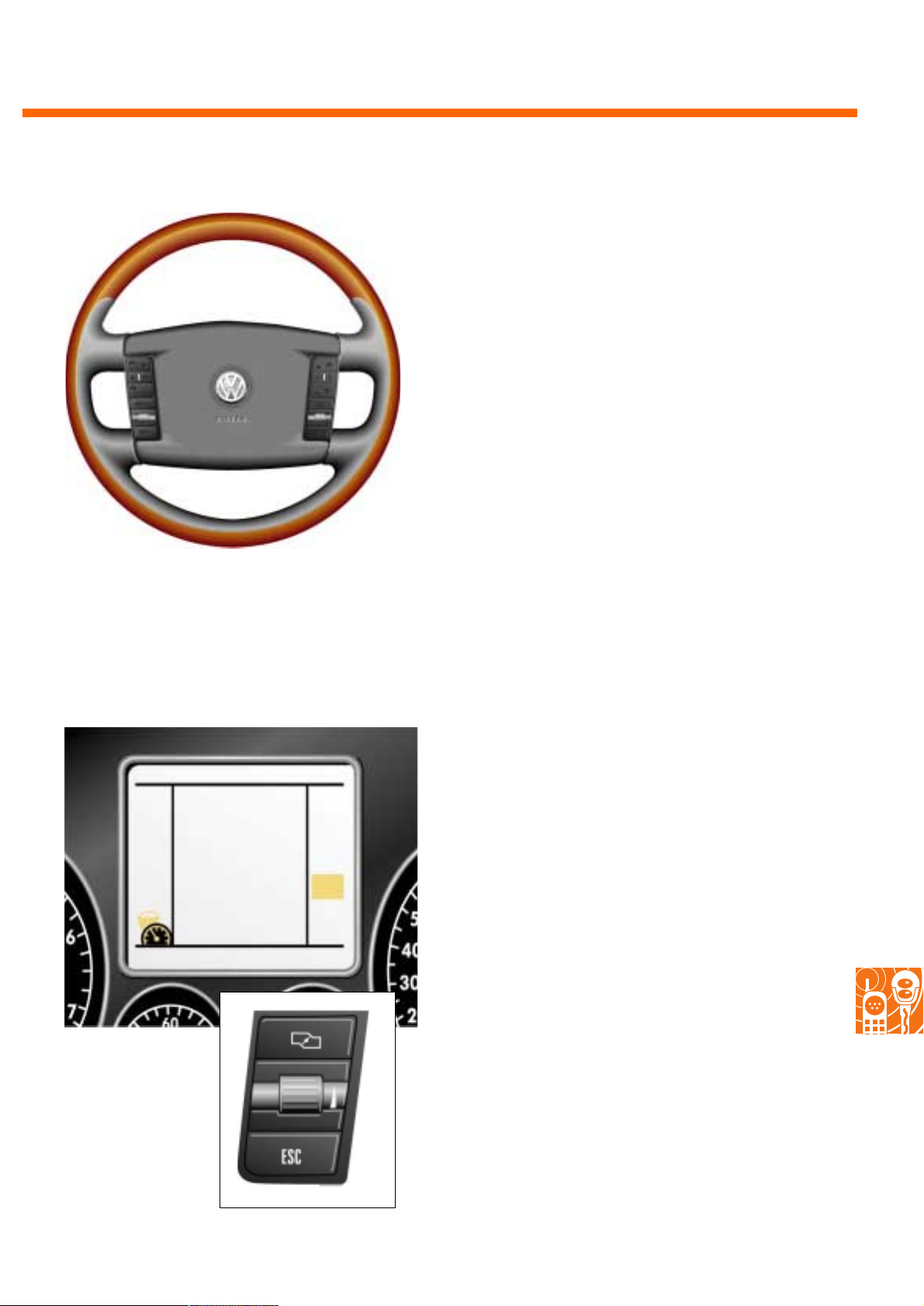
270_067
Steering wheel control
In addition to the horn, the inside of the multifunctional steering wheel accommodates two
keypads for actuating the following functions:
- Cruise control system (GRA),
- Automatic distance control system (ADC),
- Infotainment subfunctions,
- Menu selection for the display in the
dash panel insert, as well as
- Voice input activation.
270_069
The dash panel insert display
Some versions are also equipped with a 3" monochrome display or a 5" colour display. They can
display 7 different menus for the various Infotainment functions.
In doing so, the displayed function from a menu
list can be selected. A menu is selected via the
multifunctional steering wheel. The display in the
display and operating unit at the front is not
affected by this selection.
Controls for the display
control at the steering
wheel
270_070
73
Page 74

Service
Inspection service innovations
● Inspections after every 60,000 km or after four years for the petrol engines
● Oil change in versions with the flexible service interval display after approx. 30,000 km or
after 15,000 km in versions with a non-flexible display
● New VW oil standard 503 01 for W12
● Replace ATF oil after 30,000 km in the W12
● Replace gearbox top mounting in the W12
(with automatic transmission and towbar) after 150,000 km
● To replace the window wiper blades, move them into the service position
via a menu item in the main display and operating unit.
● To adjust the headlights, move the headlight washer jets into a service position
via a menu item in the main display and operating unit.
New special tools for Phaeton expertise centres
● Engine hoist VS 6100
● Engine and gearbox bracket VAS 6095
● Bracket for seat repair VAS 6136
● Upholsterer tool set VAS 6137
● Scissor lifting table VAS 6131
● Adapter for V.A.G. 1342
● Exhaust gas analyser probe VAS 1787/7A
● Exhaust gas analyser probe VAS 1788/13A
● Adapter for remote control V.A.G. 1348/3-3
● Cooling system filling device VAS 6096
● Fill plug set VAS 6122
● Upgrade set for PAX tyres VAS 6134/1
● Attachment set VAS 6130
● Portal calibre supplement VAS 5007/14
● Mudguard protector / front covering
VAS 6133
● Masking film for dash panel VAS 1474/18
● ADC adjustment appliance VAS 6041
● Compression tool for buckle assembly T10150
74
Page 75

Notes
75
Page 76
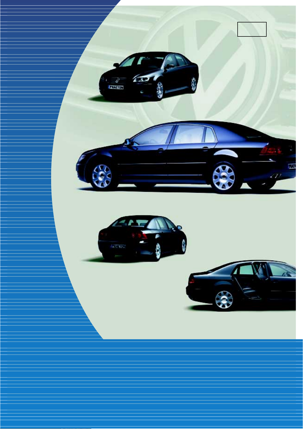
270
Only for internal use © VOLKSWAGEN AG, Wolfsburg
All rights reserved
140.2810.89.20 Issued 03/02
❀ No chlorine was used to bleach this paper
during manufacture.
 Loading...