


Technical Data Manual
Model Nos. and pricing: see Price List
Vacuum tube collector based on the heat pipe principle For the utilisation of solar energy
VITOSOLr 200-T SPE
Product may not be exactly as shown
VITOSOL 200-T Type SPE
Vacuum tube collector
For the heating of DHW, supplement heating systems and swimming pool water via heat exchangers as well as for the generation of process heat.
For installation on pitched and flat roofs, as well as for freestanding installations.
5693 556 v1.0
Product Information
Product Description
Benefits
■Highly efficient vacuum tube collector based on the heat pipe principle for high operational reliability. Optimized for horizontal installation on flat roofs.
■Optimized tube spacing prevents shading.
■Can be universally installed anywhere, either vertically or horizontally, on roofs as well as for horizontal and freestanding installation.
■The absorber areas with a highly selective coating are integrated into the vacuum tubes and therefore are not susceptible to contamination.
■Efficient heat transfer through fully encapsulated condensers.
■Tubes can be rotated (up to 45°) for optimum alignment with the sun, thereby maximizing the energy utilisation.
■Dry connection, meaning tubes can be fitted or replaced when the system is fully operational.
■Highly effective thermal insulation for minimized heat losses from the header casing.
■Easy installation through the Viessmann assembly and connection systems.
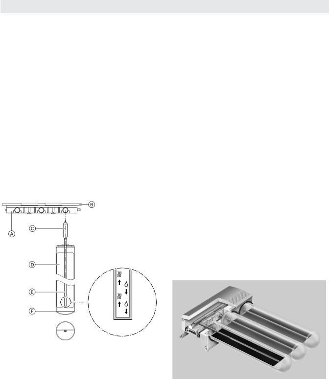
Legend
A Heat exchanger block made from aluminium and copper B Copper manifold
C Condenser
D Absorber E Heat pipe
F Evacuated glass tube
The Vitosol 200-T, type SPE vacuum tube collector is available in the following versions:
■1.63 m2 with 9 tubes
■3.26 m2 with 18 tubes.
2
Vitosol 200-T, SPE Technical Data
The Vitosol 200-T, type SPE can be installed on sloped or flat roofs as well as horizontally (laying flat) or freestanding. On sloped roofs the collectors may be positioned vertically (tubes at right angles to the roof ridge) or horizontally (tubes parallel to the roof ridge).
A highly selectively coated metal absorber is incorporated inside each vacuum tube. It ensures high absorption of insolation and low emissions of thermal radiation.
A heat pipe filled with an evaporation liquid is arranged on the absorber. The heat pipe is connected to the condenser. The condenser is located inside a heat exchanger designed as a block made from aluminium and copper.
The system is referred to as a “dry connection”,
i.e. tubes can be rotated and replaced even when the system is filled and is pressurised. The heat is transferred from the absorber to the heat pipe. This causes the liquid to evaporate. The vapor rises into the condenser. Heat is transferred by the heat exchanger with its copper manifold, inside which lies the condenser, to the
heat transfer medium streaming past, and the vapor condenses. The condensate returns back down into the heat pipe and the process repeats.
The angle of inclination must be greater than zero to guarantee circulation of the evaporator liquid in the heat exchanger. Deviations from south can be partially compensated for by rotating the vacuum tubes.
Up to 215 ft2 (20 m2) absorber area can be connected to form one collector array. For this purpose, the standard delivery includes flexible connection pipes with O-rings. A connection set with clamping ring fittings enables the collector array to be readily connected to the pipes of the solar circuit. The collector temperature sensor is fitted into a sensor well inside the collector header casing.
Delivered condition
Packed in separate boxes:
■Vacuum tubes, 9 pieces per box
■Header casing with tube retainer rails
5693 556 v1.0

Vitosol 200-T, SPE Technical Data |
|
Product Information |
||
|
|
|
|
|
Specification |
|
|
|
|
|
|
|
|
|
|
|
|
|
|
Vitosol 200-T |
|
1.63 m2 |
3.26 m2 |
|
Number of tubes |
|
9 |
18 |
|
Gross area |
ft2 (m2) |
28.63 (2.66) |
57.26 (5.32) |
|
Absorber area |
ft2 (m2) |
17.55 (1.63) |
35.10 (3.26) |
|
Aperture area |
ft2 (m2) |
18.84 (1.75) |
37.57 (3.49) |
|
Installation position (see figure below) |
|
A, B, C, D, E, F |
||
Spacing between collectors |
in. (mm) |
1.73 (44) |
1.73 (44) |
|
Dimensions |
|
|
|
|
Width |
in. (mm) |
48 (1220) |
94 (2390) |
|
Height |
in. (mm) |
89 (2260) |
89 (2260) |
|
Depth |
in. (mm) |
6.85 (174) |
6.85 (174) |
|
The following values apply to the absorber area: |
|
|
|
|
(as tested by TUV testing laboratories in Europe) |
|
|
|
|
– Optical efficiency |
% |
73 |
73 |
|
– Heat loss factor k1 |
k1 W/(m2 · K) |
1.21 |
1.21 |
|
– Heat loss factor k2 |
k1 W/(m2 · K2) |
0.0075 |
0.0075 |
|
Thermal capacity |
kJ/(m2 · K) |
8.4 |
8.4 |
|
Weight |
lb(kg) |
126 (57) |
249 (113) |
|
Liquid content |
USG (L) |
0.124 (0.47) |
0.243 (0.92) |
|
(heat transfer medium) |
|
|
|
|
Permissible operating pressure |
psig (bar) |
87 (6) |
87 (6) |
|
Maximum stagnation temperature |
°F (°C) |
518 (270) |
518 (270) |
|
Connection |
Ø in. (Ø mm) |
¾ (22) |
¾ (22) |
|
Tested quality
The collectors meet the requirements of the “Blue Angel” eco-label to RAL UZ 73.
Tested in accordance with Solar KEYMARK, EN 12975 and SRCC 0G-100
5693 556 v1.0
CR |
Collector return |
|
|
|
CS |
Collector supply |
|
|
|
|
|
|
|
|
Vitosol 200-T |
|
1.63 m2 |
3.26 m2 |
|
a |
in. (mm) |
|
48 (1220) |
94 (2390) |
|
|
|
|
|
3

Design Information
Vitosol 200-T, SPE Technical Data
Installation on Sloped Roofs
Required roof area
Vitosol 200-T |
1.63 m2 |
3.26 m2 |
|||
|
|
Vertical installation |
Horizontal installation |
Vertical installation |
Horizontal installation |
|
|
|
|
|
|
a |
in. |
98.4 |
57.9 + 1.75* |
98.4 |
104 + 1.75* |
|
(mm) |
(2500) |
(1470 + 44*) |
(2500) |
(2640 + 44*) |
|
|
|
|
|
|
b |
in. |
57.9 + 1.75* |
98.4 |
104 + 1.75* |
98.4 |
|
(mm) |
(1470 + 44*) |
(2500) |
(2640 + 44*) |
(2500) |
|
|
|
|
|
|
*space between collectors if multiple units are installed in an array. Add dimension b for each additional collector.
Installation with roof brackets |
Mounting bracket |
■This method of fixing can be applied universally on all common roof covers.
■The fixing system comprises roof brackets, mounting rails, clamping brackets and screws.
■Forces are applied to the roof structure in various ways, including via the roof brackets and the roof cover. Roof covers can be very different. Consequently, damage cannot be completely excluded in the case of applied loads.
Note: During installation, e.g. on sheet steel roofs, the mounting rails are secured directly on to the mounting brackets with T-bolts.
Use on-site fixing options to secure the brackets, to the substructure.
4
5693 556 v1.0
 Loading...