

Page 1
INST ALLATION, OPERA TION, AND MAINTENANCE INSTRUCTIONS
PD-2, PD-2/SW, PD-2/HT, & PD-2/SW HT
PRESSURE DIFFERENTIAL GAUGE KITS
RECOMMENDED FOR INSTALLATION ON F101 SERIES FILTERS
SPECIFICA TIONS
PD-2 KIT p/n 84-0129
MAX. OPERATING PRESSURE ..................... 200 PSIG
MAX. OPERATING TEMPERATURE .............. 150OF
OPERATING RANGE ...................................... 0-15 PSID
GAUGE DIMENSIONS..................... 4"L, 1.5"W, 2.0625"H
PRESSURE PORT CONNECTIONS .............. 1/8" NPT
PD-2/HT KIT p/n 84-0130 (Same as 84-0129 except)
MAX. OPERATING PRESSURE ..................... 3000 PSIG*
MAX. OPERATING TEMPERATURE .............. 175OF*
*NOTE: SEE F101 SERIES FILTER RATINGS.
INSTALLATION
WARNING
CAREFULLY READ THESE INSTRUCTIONS BEFORE INSTALLING THE
PRESSURE DIFFERENTIAL KIT.
FIGURE 1 INST ALLATION
FOR
PD-2/SW KIT p/n 84-0131
MAX. OPERATING PRESSURE ..................... 200 PSIG
MAX. OPERATING TEMPERATURE .............. 150OF
OPERATING RANGE ...................................... 0-15 PSID
GAUGE DIMENSIONS.....................4"L, 2.375"W, 3.75"H
PRESSURE PORT CONNECTIONS .............. 1/8" NPT
CONDUIT PORT CONNECTION ................... 1/2" NPT
SWITCH RATINGS
SET POINT (adjustable)0-15 PSID
ELECTRICAL ............... 110V/1PH/60Hz, 1/2 AMP, 50 WATTS
TYPE ............. SPST (Single Pole Single Throw)
PD-2/SW HT KIT p/n 84-0211 (Same as 84-0131 except)
MAX. OPERATING PRESSURE ..................... 3000 PSIG
MAX. OPERATING TEMPERATURE .............. 175
O
F
OCTOBER 2004
P/N 30-0602 REV A
MAKE SURE THAT THE COMPONENT
OR PIPING IS DEPRESSURIZED
BEFORE INSTALLING THE PRESSURE
DIFFERENTIAL KIT.
COMPLY WITH ALL APPLICABLE
ELECTRICAL CODES IF INSTALLING A
PD-2/SW OR PD-2/SW HT KIT.
Completely depressurize the piping and
component that the kit is to be installed on.
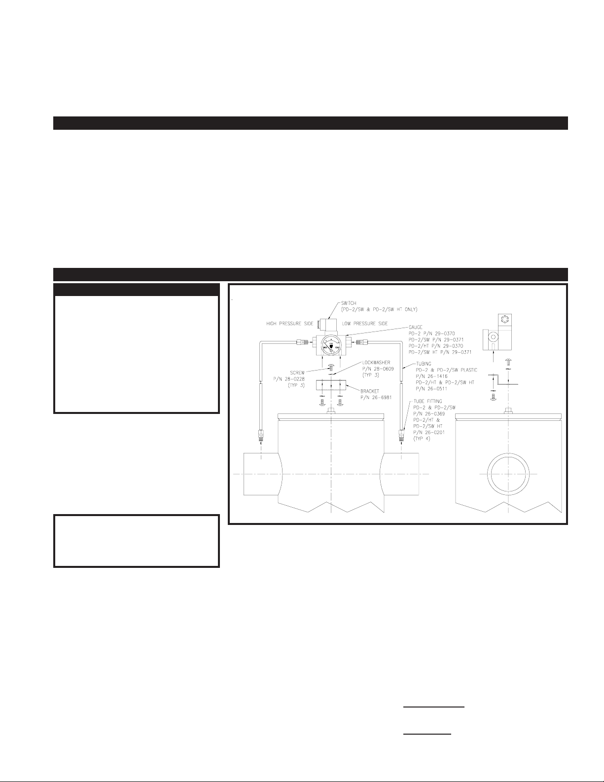
Figure 1 shows a typical assembly/installation
of the PD-2 series pressure differential gauge
on a VAN AIR F101 series filter housing.
Mount the gauge on the mounting bracket.
Use the fasteners provided with the kit. Mount
the kit to the desired surface.
IMPORTANT
To ensure an accurate reading, make
sure that both tubing lines to the
gauge are equal in length. Use as few
bends as possible in the tubing lines.
Install the necessary tubing from the inlet side
of the vessel or piping to be measured to the
HIGH PRESSURE port of the gauge. Use the
tubing and fittings as shown in FIGURE 1. Use
pipe sealant on all threaded pipe connections.
Complete the tubing connection from the outlet
side of the vessel or piping to be measured to
the LOW PRESSURE port of the gauge. Use
the tubing and fittings as shown in FIGURE 1.
Use pipe sealant on all threaded pipe connections.
SWITCH CONNECTIONS AND
ADJUSTMENTS (PD-2/SW PD-2/SW HT)
CONNECTING THE SWITCH
The gauges are equipped with an electric
switch. This switch can be used to activate
an alarm to alert personnel that the
pressure differential across the measure
piping or vessel has reached an unacceptable level. The set point of the switch is
adjustable.
The valve is tapped with 1/2" NPT conduit
connections. Conduit can be run from the
gauge to the alarm panel.
Make the necessary wiring connections
from the gauge to the alarm panel.
Reference FIGURE 1.
ADJUSTING THE SWITCH SET POINT
The gauge switch is adjustable. It should
be set at the pressure differential reading
that you want to activate the alarm device.
If the gauge is installed on a filter set it at
the recommended element replacement
pressure differential, reference filter manual
for this setting.
Make sure that the piping or vessel that the
gauge is connected to is depressurized.
Disconnect the tubing from the HIGH
PRESSURE port on the gauge.
Using a clean, dryer source of compressed
air and a pressure regulator slowly apply
pressure to the HIGH PRESSURE port until
the gauge reads the desired set point.
Loosen the adjustment screw on the top of
the gauge. Use a voltmeter to check the
position of the switch. Slide the adjustment
screw until the switch is closed at the
desired pressure on the gauge. NOTE, The
screw may be difficult to slide. This is
normal.
Once the switch is properly set, tighten the
adjustment screw. Reconnect the sample
tubing to the HIGH PRESSURE port.
MAINTENANCE: PER GAUGE INSTRUCTIONS.
WARRANTY: PER TERMS AND CONDITIONS OF SALE.
 Loading...