

Page 1
INSTALLATION, OPERATION & MAINTENANCE INSTRUCTIONS
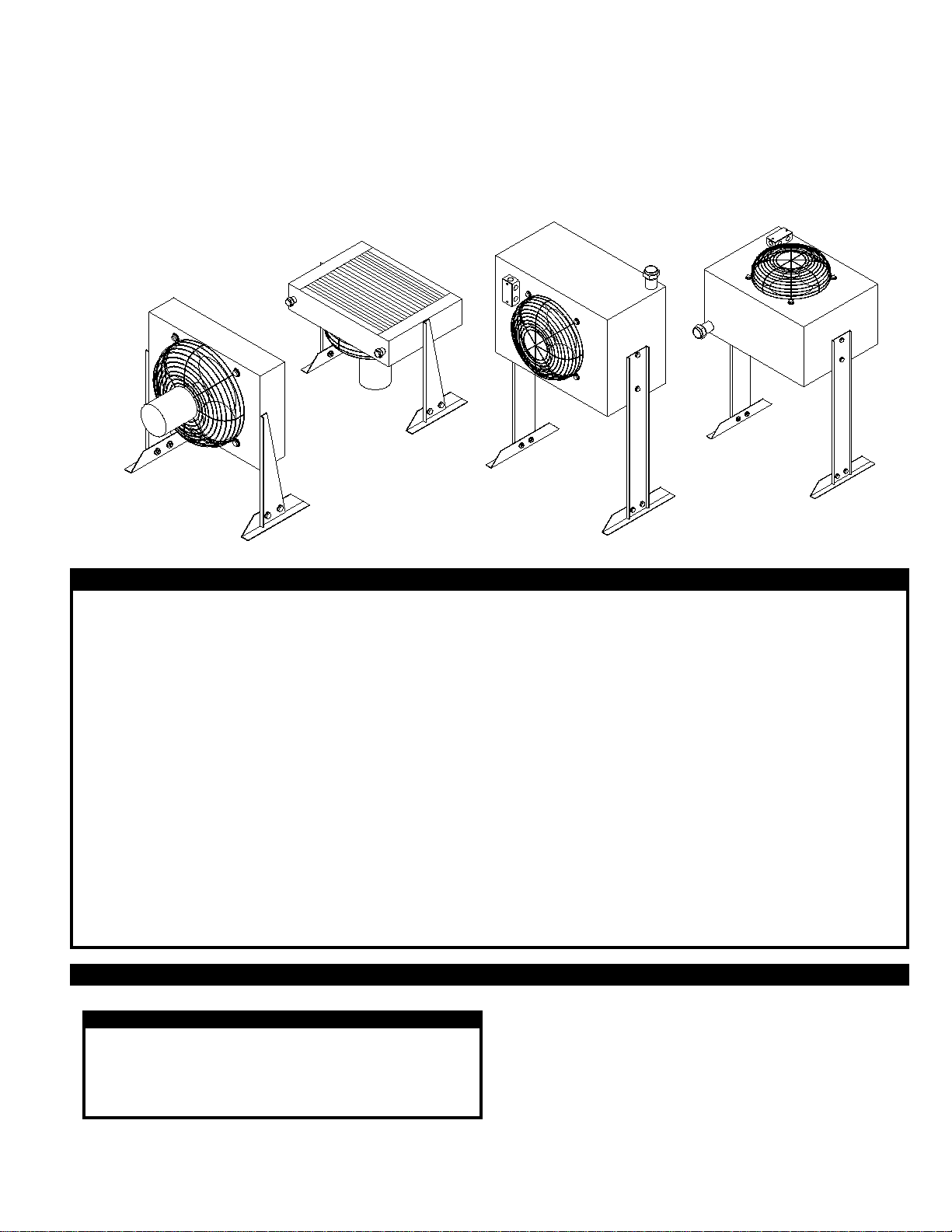
AIR-COOLED AFTERCOOLER
FOR COMPRESSED AIR SYSTEMS
MODELS AC-10-1 thru AC-40-1
AUGUST 1995
P/N 32-0224
WARNING
BEFORE STARTING INSTALLATION OR MAINTENANCE PROCEDURES, TURN OFF ELECTRICAL POWER AND
COMPLETELY DEPRESSURIZE THE UNIT. FAILURE TO HEED THIS WARNING MAY RESULT IN SERIOUS PERSONAL
INJURY AND/OR DAMAGE TO THE UNIT.
NEVER REMOVE, REPAIR, OR REPLACE ANY ITEM ON THIS UNIT WHILE IT IS UNDER PRESSURE.
WHEN INSTALLING THIS UNIT, ALWAYS COMPLY WITH THE NATIONAL ELECTRICAL CODE AND ALL OTHER
APPLICABLE FEDERAL, STATE AND LOCAL CODES.
NEVER OPERATE THIS AFTERCOOLER IF THERE IS A LEAK IN THE CORE. IMMEDIATELY TAKE THE UNIT OUT OF
SERVICE AND FIX OR REPLACE THE CORE.
NEVER OPERATE THE AFTERCOOLER ABOVE THE MAXIMUM RATED OPERATING CONDITIONS, AS OUTLINED IN
SECTION 3.1.
NEVER REMOVE THE FAN GUARD WHILE THE AFTERCOOLER IS OPERATING. CONTACT WITH THE ROTATING FAN
BLADE(S) MAY RESULT IN SERIOUS PERSONAL INJURY.
DURING NORMAL OPERATION, THE INLET PIPING MAY REACH TEMPERATURES OF 150oF TO 400oF. CONTACT WITH
THE PIPING MAY RESULT IN SERIOUS PERSONAL INJURY.
HANDLING INSTRUCTIONS SECTION 1
1.1 HANDLING THE AFTERCOOLER
CAUTION
NEVER LIFT THE AFTERCOOLER BY THE CORE OR
INLET AND OUTLET..
1.2 EQUIPMENT CHECK
Inspect the aftercooler for any damage that may have
occured during shipment. Inspect all items shipped with
the unit.
WHEN MOVING OR LIFTING THE UNIT, PROTECT
THE CORE FROM ACCIDENTAL DAMAGE.
Take extreme care when unpacking, moving or installing. The
core is exposed. Damage to the core or fins may render the
unit inoperable.
PRINTED IN THE U.S.A. © 1995 VAN AIR SYSTEMS INC. 2950 MECHANIC STREET, LAKE CITY, PA 16423 PAGE 1
IF THE UNIT HAS BEEN DAMAGED DURING SHIPMENT:
(1) Notify carrier immediately
(2) DO NOT operate the unit before consulting factory
Page 2
ASSEMBLY, LEG INSTALLATION SECTION 2
2.1 INSTALLING THE LEGS
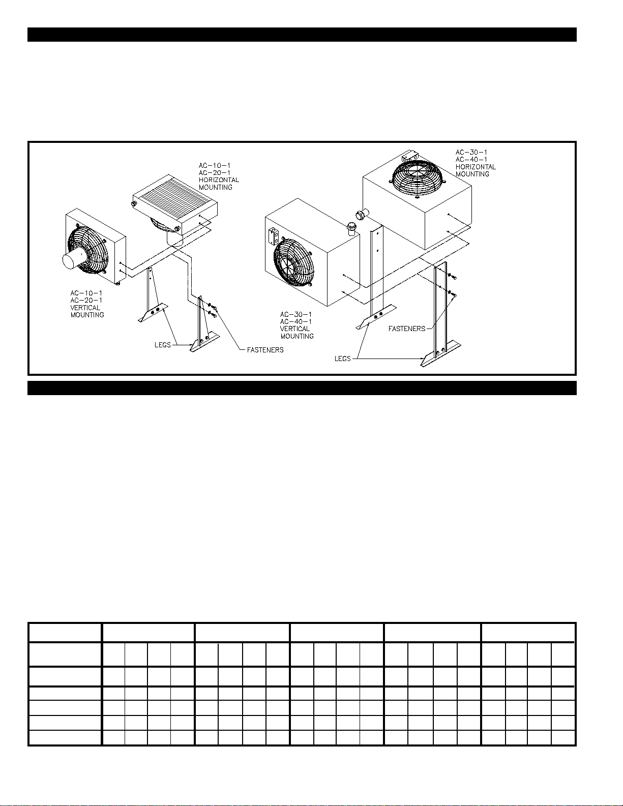
This unit was shipped without the legs installed. The legs
should be installed before placing the aftercooler in the
piping system.
The legs can be mounted two ways:
1. Core mounted horizontally
2. Core mounted vertically
FIGURE 1 LEG INSTALLATION DETAIL
Determine the desired position for your installation. Place the
aftercooler in that position (horizontal or vertical). Carefully lift
and support the unit approximately 1 to 2 feet from the floor.
Position the legs against the unit and fasten them in place
using the fasteners provided. Make sure the fasteners are
tightened in place.
SPECIFICATIONS AND DIMENSIONS SECTION 3
3.1 SPECIFICATIONS
WEIGHT
AC-10-1............... 25 LBS AC-20-1..............27 LBS
AC-30-1............... 61 LBS AC-40-1..............67 LBS
DIMENSIONS .............. See Section 3.2
INLET/OUTLET CONNECTIONS
AC-10-1........1/2" NPT (F) AC-20-1 ...... 1/2" NPT (F)
AC-30-1........1" NPT (F) AC-40-1 ..... 1-1/2" NPT (F)
MAXIMUM WORKING PRESSURE
ALL MODELS ............ 250 PSIG
MAXIMUM WORKING TEMPERATURE
ALL MODELS ............ 3 50OF
MAXIMUM CAPACITY (SCFM)
Rated capacities are based on the following conditions: Inlet and approach temperature at inlet pressures 80 to 125 PSIG.
Approach Temperature: The number of degrees above the temperature of the cooling medium (in this case ambient air) to
which the aftercooler reduces the compressed air. A higher approach does not mean better performance.
INLET TEMP.
APPROACH
TEMP. OF
MODEL
AC-10-1
AC-20-1
AC-30-1
AC-40-1
150OF 200OF 350OF250OF 300OF
10
5
17
29
43
95
35*
43*
72
125*
15
35*
43*
72*
125*
20
35*
43*
72*
125*
11
17
28
66
5
10
15
20
22
35
35*
36
43*
43*
50
70
72*
111
125*
125*
ELECTRICAL REQUIREMENTS
ALL MODELS ............ 115V-1PH-60Hz, w/ ODP motor
MATERIALS OF CONSTRUCTION
CABINET.................... Steel with baked enamel finish
FAN GUARD .............. Steel, zinc chromate plated
FAN ............................ Heavy gauge aluminum with steel hub
CORE ......................... Aluminum fins on copper tubes
MOTOR...................... Open vented
MOTOR SPECIFICATIONS AND DATA
See Wiring Diagram, Figure 5 on page 6.
FAN DATA (AMBIENT AIR FLOW)
AC-10-1 & AC-20-1.... 615 SCFM
AC-30-1 & AC-40-1.... 945 SCFM
5
10
15
20
5
10
15
20
5
10
8
16
20
35
6
12
19
26
5
10
12
27
35
43*
10
20
31
42*
8
16
22
35
50
70
18
32
45
57
15
28
52
88
100
125*
44
74
100
125
38
64
15
15
26
39
86
20
21
35
50
108
MAXIMUM PRESSURE DROP LESS THAN 3 PSI.
* Maximum ratings restricted by pressure drop: actual thermal capacities are higher.
PAGE 2 © 1995 VAN AIR SYSTEMS INC. 2950 MECHANIC STREET, LAKE CITY, PA 16423 PRINTED IN THE U.S.A.
Page 3
SPECIFICATIONS AND DIMENSIONS SECTION 3
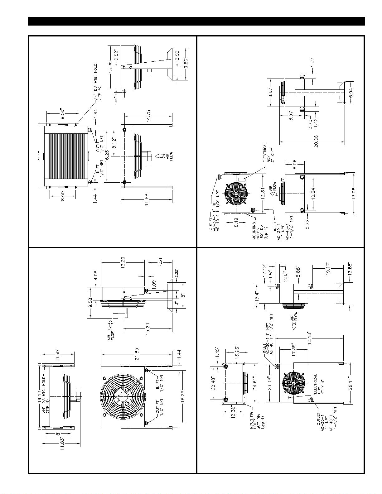
3.2 DIMENSIONS AND COMPONENT LOCATIONS
AC-10-1& AC-20-1
CORE MOUNTED
HORIZONTALLY
AC-30-1& AC-40-1
CORE MOUNTED
HORIZONTALLY
AC-30-1& AC-40-1
CORE MOUNTED
VERTICALLY
AC-10-1& AC-20-1
CORE MOUNTED
VERTICALLY
PRINTED IN THE U.S.A. © 1995 VAN AIR SYSTEMS INC. 2950 MECHANIC STREET, LAKE CITY, PA 16423 PAGE 3
Page 4
INSTALLATION SECTION 4
4.1 LOCATION
CAUTION
DO NOT LOCATE THIS AFTERCOOLER WHERE
PERSONNEL MAY CONTACT THE INLET PIPING
UNLESS THE UNIT IS PROTECTED BY WARNING
SIGNS AND/OR A BARRIER. DURING NORMAL
OPERATION, THE INLET PIPING MAY BECOME
EXTREMELY HOT (150OF TO 400OF). CONTACT MAY
RESULT IN SERIOUS PERSONAL INJURY.
DO NOT INSTALL THIS UNIT IN AN ENVIRONMENT OF
CORROSIVE GASES OR CHEMICALS. MAKE SURE
THAT THE MATERIALS USED IN THIS UNIT (listed on
page 2) ARE COMPATIBLE WITH THE ATMOSPHERIC
CONDITIONS.
Mount the unit using hardware (not supplied) sized for the
mounting holes.
4.3 FLEXIBLE HOSE INSTALLATION
IMPORTANT
A FLEXIBLE HOSE MUST BE INSTALLED BETWEEN
THE COMPRESSOR AND AFTERCOOLER TO
VALIDATE THE WARRANTY ON THE AFTERCOOLER.
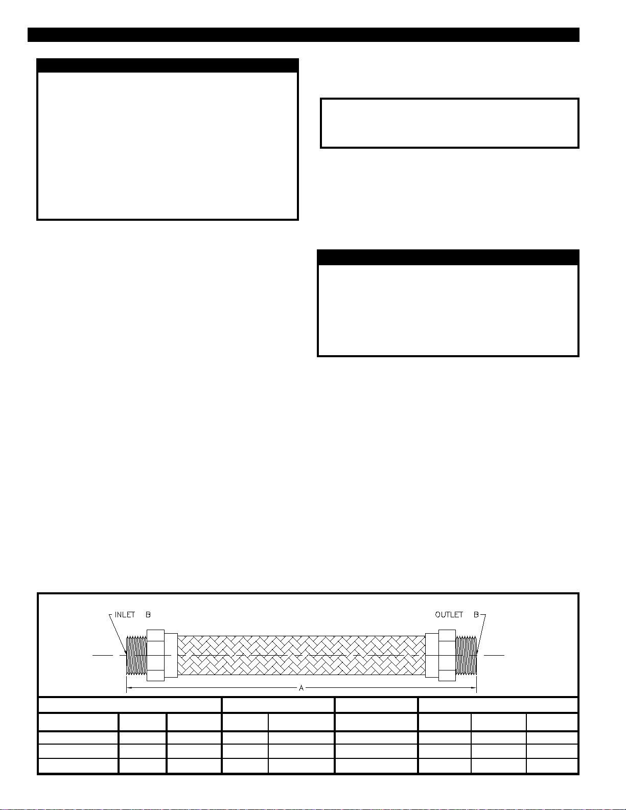
The flexible hose must be installed perpendicular to the
direction of vibration from the compressor.
If a flexible hose was not ordered with the aftercooler, one can
be ordered from your Van Air distributor. Figure 2 lists the
hose required for each aftercooler model.
The aftercooler should be located far enough away from the
compressor so that there are no vibrations transmitted from the
compressor. A FLEXIBLE HOSE MUST BE INSTALLED IN
THE PIPING TO VALIDATE THE WARRANTY AND TO
PREVENT DAMAGE TO THE AFTERCOOLER FROM
VIBRATION IN THE PIPING! REFERENCE Section 4.3 for
instructions.
The location should be level and capable of supporting the
aftercooler and all components and piping to be installed. The
aftercooler must be level to allow proper drainage of fluids from
the outlet manifold.
The aftercooler must be installed at least 1 foot from walls or
obstructions. It is important for the unit to have an adequate
air supply for cooling at all times. If more than one unit is to be
installed in the same area, allow at least 1 foot between them.
This unit must be installed indoors. If the unit is to be installed
in an area where ambient temperatures can fall below 35
o
precautions must be taken to prevent freeze-up and damage to
the unit. The drain lines and separator must be heat traced
and/or insulated and the unit should be protected from the
wind. REFERENCE Section 4.5 for details.
4.2 MOUNTING THE UNIT
After selecting the proper location as outlined above, the
aftercooler should be mounted to the installation surface.
Mounting holes are provided on the leg support braces.
Reference Section 3.2, on page 3 for mounting hole locations
and dimensions.
F,
4.4 PIPING INSTALLATION
CAUTION
ALL PIPING MUST BE ADEQUATELY SUPPORTED
AND ISOLATED FROM VIBRATION. EXCESSIVE
STRESS OR VIBRATION IN THE PIPING WILL CAUSE
DAMAGE TO THE AFTERCOOLER CORE.
TO ENSURE PROPER OPERATION, MAKE SURE THAT
THE INLET AND OUTLET PIPING ARE CORRECTLY
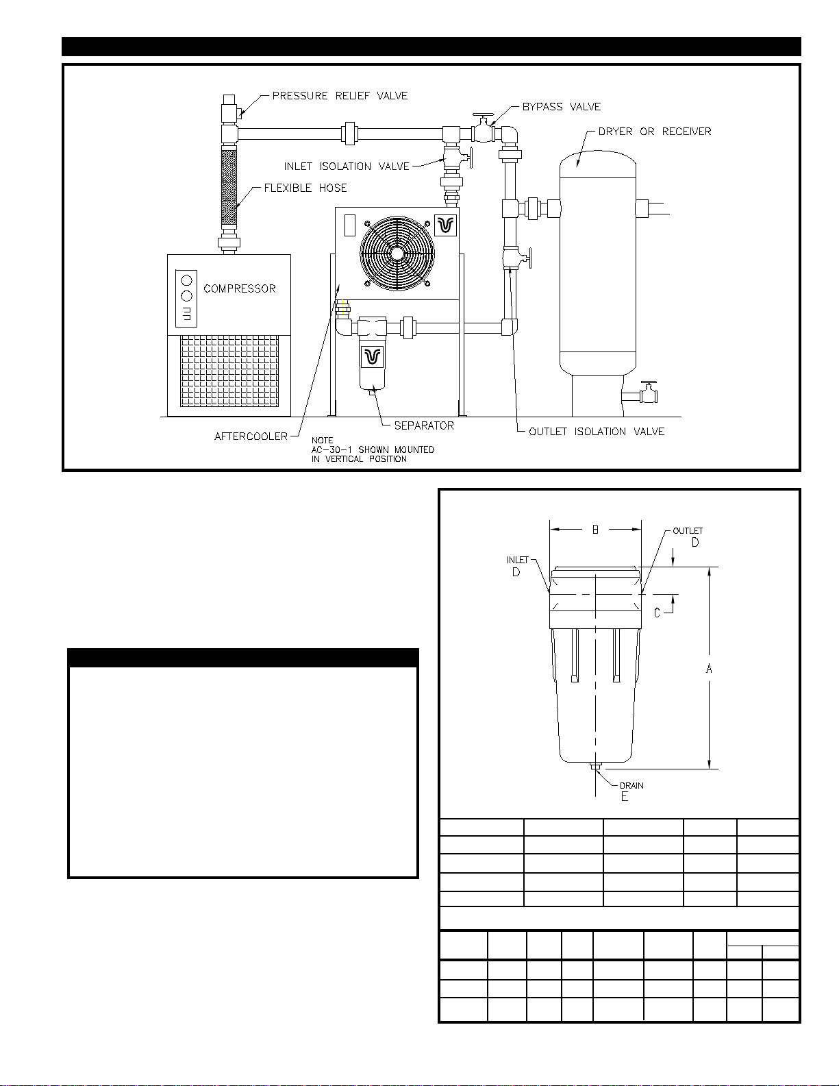
CONNECTED TO THE UNIT. REFERENCE FIGURE 3.
If the aftercooler is to be installed in an existing piping system,
clean the piping to remove accumulated dirt, pipe scale, oil,
and other contaminants before installing the unit.
A properly sized pressure relief valve should be installed after
the compressor and before any block valves. The relief valve
should be installed in compliance with any applicable federal,
state, or local codes.
To isolate the aftercooler for maintenance, install bypass piping
around the aftercooler and separator (if installed). Reference
Figure 3.
Connect the inlet piping to the inlet of the aftercooler, reference
Section 3.2 for location. Make sure that the flexible hose is
properly installed before the aftercooler inlet. Provide supports
wherever necessary to prevent stress on the aftercooler.
Supports should be installed close to the inlet and outlet
manifolds. Use either overhead or stiff-leg type supports.
FIGURE 2 FLEXIBLE HOSE DETAILS
DIMENSIONS
MODEL
AC-10-1 & AC-20-1
AC-30-1
AC-40-1
PAGE 4 © 1995 VAN AIR SYSTEMS INC. 2950 MECHANIC STREET, LAKE CITY, PA 16423 PRINTED IN THE U.S.A.
HOSE
FH-1/2
FH-1
FH-1-1/2
PART NO.
83-0734
83-0735
83-0736
A
10"
12"
16"
B
1/2" NPT
1" NPT
1-1/2" NPT
WEIGHT
2.0 LBS
2.0 LBS
3.0 LBS
MAXIMUM WORKING PRESSURE
70OF
1000 PSIG
525 PSIG
450 PSIG
300OF
900 PSIG
460 PSIG
395 PSIG
400OF
863 PSIG
435 PSIG
370 PSIG
Page 5
INSTALLATION SECTION 4
FIGURE 3 RECOMMENDED INSTALLATION DETAIL
4.5 FREEZE PROTECTION
If the aftercooler is to be installed in a location where ambient
FIGURE 4 SEPARATOR DETAILS
temperatures may fall below 35oF, heat tracing and/or insulation must be used on the outlet piping to the separator, the
separator, and the drain piping. The aftercooler must be
protected from the direct wind, i.e. a roof and/or walls.
The aftercooler should be turned off when ambient temperatures fall below 35oF.
4.6 SEPARATOR INSTALLATION
CAUTION
WHEN INSTALLING THE SEPARATOR, NEVER REDUCE
THE PIPING SIZE BETWEEN THE AFTERCOOLER AND
SEPARATOR. THIS MAY CAUSE INADEQUATE
DRAINING OF THE AFTERCOOLER AND POSSIBLE
BACK PRESSURE OR INCREASED PRESSURE DROP.
IF THE SEPARATOR DRAIN IS TO BE CONNECTED
INTO A REMOTE OR COMMON DRAIN LINE, MAKE
SURE THAT IT IS VENTED.
THE DISCHARGE FROM THE SEPARATOR MAY
CONTAIN COMPRESSOR LUBRICANTS. COMPLY WITH
ALL REGULATIONS CONCERNING DISPOSAL OF SUCH
FLUIDS.
When the system air is cooled by the aftercooler, moisture in
AFTERCOOLER
AC-10-1
AC-20-1
AC-30-1
AC-40-1
the compressed air condenses and accumulates in the outlet of
the aftercooler. To efficiently remove this liquid from the air
system, a separator with a FD-1 float drain must be installed
immediately downstream of the aftercooler.
Install the separator as outlined in the Installation, Operation,
and Maintenance Instructions supplied with the component. If
a separator was not ordered with the aftercooler, one can be
MODEL
S-5-AD
S-10-AD
S-30-M
ordered from your VAN AIR distributor.
PRINTED IN THE U.S.A. © 1995 VAN AIR SYSTEMS INC. 2950 MECHANIC STREET, LAKE CITY, PA 16423 PAGE 5
A
7.35"
10.00"
12.10"
SEPARATOR
S-5-AD
S-5-AD
S-10-AD
S-20-M
B
C
3.25"
0.98"
4.75"
1.00"
4.38"
2.30"
PART NO.
83-0742
83-0742
83-0744
83-0745
D
1/2" NPT
1" NPT
1" NPT
E
1/8" NPT
1/8" NPT
1/4" NPT
DRAIN
FD-1
FD-1
FD-1
FD-1
MWP
(PSIG)
200
200
200
PART NO.
83-0751
83-0751
83-0751
83-0751
FLOW (SCFM)
MIN
MAX
5
50
11
120
60
400
Page 6
5.3 REPAIRING LEAKS
INSTALLATION SECTION 4
4.7 ELECTRICAL CONNECTIONS
CAUTION
TURN OFF MAIN POWER SUPPLY BEFORE WIRING TO
THE AFTERCOOLER.
MAKE SURE THAT ALL USER SUPPLIED WIRING IS
PROPERLY SIZED TO HANDLE THE AMPERAGE
REQUIRED BY THE AFTERCOOLER AND ANY
ADDITIONAL EQUIPMENT.
WHEN WIRING TO THIS UNIT AND ANY OTHER
ELECTRICAL COMPONENTS, ALWAYS COMPLY WITH
THE NATIONAL ELECTRICAL CODE AND ALL
APPLICABLE FEDERAL, STATE AND LOCAL CODES.
IF THE AFTERCOOLER IS TO BE INSTALLED
OUTDOORS OR IN AN EXTREMELY HUMID
ATMOSPHERE, MAKE SURE THAT ALL WIRING AND
COMPONENTS ARE PROPERLY RATED.
VERIFY THAT THE POWER SOURCE MATCHES THE
AFTERCOOLER ELECTRICAL REQUIREMENTS
BEFORE MAKING ANY CONNECTIONS. REFERENCE
EQUIPMENT DATA TAG AND FIGURE 4 FOR
INFORMATION.
TO PREVENT POSSIBLE ELECTRICAL SHOCK, IT IS
IMPORTANT THAT THIS UNIT IS GROUNDED.
ALWAYS USE THE PROVIDED GROUNDING SCREW.
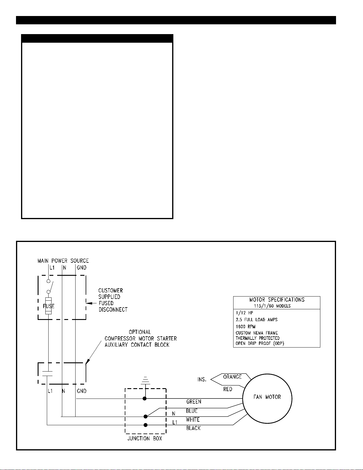
The aftercooler electrical requirements are listed on the
equipment data tag and in Figure 5. If there are any discrep-
ancies between the data tag and Figure 5, use the information
on the tag.
Remove the cover from the electrical junction box on the
aftercooler motor. Using FIGURE 5 as reference, make the
necessary wiring connections. Several ways to wire the unit
are listed below. Make the connections for the pertinent
application(s).
1. DEDICATED POWER SUPPLY AND DISCONNECT
Install a properly sized fused disconnect before the
aftercooler.
Make the necessary wire connections and re-install the
junction box cover.
2. INTERLOCKED WITH COMPRESSOR MOTOR STARTER
The aftercooler can be interlocked with the air compressor
starter. This allows the aftercooler to operate only when the
air compressor is operating.
If a set of auxiliary, normally open contacts is available on
the air compressor magnetic starter, make necessary wiring
connections from the contacts to the aftercooler.
If a set of auxiliary contacts is not available, use a properly
sized contactor. Wire the contactor's holding coil in parallel
with the air compressor starter holding coil. Make the
necessary wiring connections from the contactor to the
aftercooler.
Re-install the junction box gasket and cover.
FIGURE 5 WIRING DIAGRAM
PAGE 6 © 1995 VAN AIR SYSTEMS INC. 2950 MECHANIC STREET, LAKE CITY, PA 16423 PRINTED IN THE U.S.A.
Page 7
OPERATION SECTION 5
5.1 START UP INSTRUCTIONS
Pressurize the compressed air system. If the aftercooler was
interlocked with the compressor, the aftercooler will begin to
operate immediately. If the aftercooler was wired on a separate electrical source, turn on the source.
Open the inlet and outlet isolation valves on the aftercooler (if
installed). Close the bypass valve. The aftercooler is ready for
operation.
5.3 SHUT DOWN INSTRUCTIONS
To shut down the aftercooler, turn off the electrical power
source. If the aftercooler was interlocked with the compressor,
the aftercooler will automatically turn off with the compressor.
Open the bypass valve and close the inlet and outlet isolation
valves (if installed).
5.2 OPERATING INSTRUCTIONS
The operation of the aftercooler is simple. The fan rotates,
moving ambient air across the core. The ambient air flow cools
the compressed air inside the core. The aftercooler will
automatically operate as long as electrical power is supplied to
the unit.
MAINTENANCE and REPLACEMENT PARTS SECTION 6
6.0 MAINTENANCE INSTRUCTIONS
WARNING
BEFORE STARTING INSTALLATION OR
MAINTENANCE PROCEDURES, TURN OFF
ELECTRICAL POWER AND COMPLETELY
DEPRESSURIZE THE UNIT. FAILURE TO HEED THIS
WARNING MAY RESULT IN SERIOUS PERSONAL
INJURY AND/OR DAMAGE TO THE UNIT.
NEVER REMOVE, REPAIR, OR REPLACE ANY ITEM ON
THIS UNIT WHILE IT IS UNDER PRESSURE.
NEVER REMOVE THE FAN GUARD WHILE THE
AFTERCOOLER IS OPERATING. PERSONAL
CONTACT WITH THE ROTATING FAN BLADE MAY
RESULT IN SERIOUS PERSONAL INJURY.
6.1 CORE EXTERIOR CLEANING
The core should be regularly cleaned. Accumulation of dirt or
other contaminants such as oils will greatly reduce the efficiency of the aftercooler.
NEVER USE SOLVENTS CONTAINING STRONG ACID
OR ALKALINE BASES TO CLEAN THE CORE.
DAMAGE TO THE CORE MAY OCCUR.
6.3 MOTOR LUBRICATION
This unit is equipped with a sleeve bearing motor. The sleeve
bearings will require lubrication at least every 6 months. Add a
few drops of S.A.E. 20 oil to each bearing.
6.4 REPLACEMENT PARTS
Replacement Cores
AC-10-1 P/N 34-0729
AC-20-1 P/N 34-0730
AC-30-1 P/N 34-0731
AC-40-1 P/N 34-0732
Replacement 12" Dia. Fan Blade
All models P/N 26-5905
CAUTION
Normal accumulation of dirt can be removed by blowing off the
core with compressed air. If the core becomes contaminated
with oil-laden particles, it can be steam cleaned. Clean with
extreme care. The aluminum fins can be easily damaged.
6.2 CORE INTERIOR CLEANING
If the compressed air system contains excessive lubricating
fluids, build-up may occur. The interior of the core may be
cleaned to remove the deposits by circulating a mild cleaning
solution through the core. For most conditions, a mild alkaline
solution such as OAKITE or equal, is satisfactory. For extreme
conditions, it might be necessary to use a weak solution of
INHIBITED hydrochloric acid.
Turn off the electrical power supply, depressurize the unit, and
disconnect it from the air system. Circulate the solution
through the core until it is clean. Make sure that the core is
rinsed out thoroughly before returning the unit to service.
When the core is cleaned, it is important that the full characteristics of the fouling material and cleaning agent be known.
Proper care must be taken when handling and disposing of the
solution. Always follow the instructions supplied with the
material.
PRINTED IN THE U.S.A. © 1995 VAN AIR SYSTEMS INC. 2950 MECHANIC STREET, LAKE CITY, PA 16423 PAGE 7
Replacement Fan Guard
AC-10-1 & AC 20-1 P/N 41-0206
AC-30-1 & AC 40-1 P/N 41-0207
Replacement 1/12 HP 115v Motor
AC-10-1 P/N 34-0742
AC-20-1 P/N 34-0742
AC-30-1 P/N 34-0743
AC-40-1 P/N 34-0743
Page 8
TROUBLESHOOTING SECTION 7
7.0 TROUBLESHOOTING
1. FAN MOTOR NOT OPERATING
Motor failure - Check electrical power source. If power supply is okay, check the motor. Replace if necessary.
Power supply failure - Check electrical power source. Check contactors, fuses, or disconnects. Check incoming wiring for
damage. If aftercooler is interlocked with the compressor, check the compressor starter.
2. HIGH AFTERCOOLER OUTLET TEMPERATURES
Fan motor not operating - Reference Problem 1.
Plugged aftercooler core or restricted air flow - Inspect the core for deposits of dirt and/or oils. If the core is contaminated,
clean it as outlined in Sections 6.1 thru 6.2. Check for obstructions around the aftercooler. Remove if present.
3. INCREASED LIQUID (WATER) CONTENT IN THE COMPRESSED AIR SYSTEM DOWNSTREAM OF THE AFTERCOOLER
Plugged or damaged separator - Check the separator for damage and proper operation.
Separator installed incorrectly - If a separator was installed, check to make sure that it was installed properly. If no separator
was installed downstream of the aftercooler, one should be installed to remove the liquid from the air system.
Separator drain plugged or damaged - Check the drain for damage and proper operation.
4. EXCESSIVE PRESSURE DROP ACROSS THE AFTERCOOLER
Aftercooler core damaged or clogged - Inspect the core for damage or blockage. If the core is damaged, repair or replace.
If the core is plugged, flush it out as outlined in Section 6.2.
WARRANTY SECTION 8
8.0 WARRANTY
I. INSTALLATION.
Unless otherwise set forth in a quotation and/or acknowledgment, Seller shall not be responsible for
installation. Cost of and all risks of damage to the equipment and/or components thereof caused by
installation shall be the sole responsibility of Buyer. If supervision of installation and/or supervision
of start up of the equipment is to be provided by Seller, Buyer shall assume all costs incurred by Seller
in furnishing supervision. If supervision of installation and/or supervision of start up of the equipment
is provided by Seller, Seller shall only be responsible for any loss or damage growing out of a direct
negligent act or acts of Seller’s supervisor.
SELLER SHALL NOT BE RESPONSIBLE FOR IMPROPER OPERATION OF THE EQUIPMENT
DUE TO FAULTY ERECTION OR INSTALLATION.
II. PERFORMANCE.
Seller shall have no responsibility for the performance of its Goods when installed under conditions
varying materially from those under which the product is usually tested or operated under existing
industry standards.
III. WARRANTY
All AC Series Aftercoolers manufactured by Seller are guaranteed to be free from defective materials
and workmanship for a period of one (1) year from date of shipment.
The above warranties for all products described do not cover abuse, neglect, lack of normal
maintenance, accidents or other exceptional circumstances.
Date of shipment will be defined as the date of departure from the factory or from distributor stock.
A copy of the distributor invoice to the customer at time of shipment is required as verification of
shipment from distributor stock. Equipment start up will be verified by receipt of the product
registration card.
Seller’s obligation under this warranty may, at its option, be discharged by refunding the price of,
furnishing or repairing, without charge, FOB its factory, a similar part to replace any part of its own
manufacture which within the above specified periods, proves to have been defective, provided that
within a reasonable time for inspection after delivery, Seller is notified of such defects and the
equipment, material or part claimed to be defective is delivered pre-paid to Seller at Lake City,
Pennsylvania with evidence that it has been properly maintained and used in accordance with
instructions. If, in connection with such warranties, repairs are performed by the Buyer with the written
authorization of Seller, then the expense in connection with such repairs shall not exceed the cost
of material and direct labor If such repairs are performed by Buyer without the written authorization
of Seller. Seller will not assume any of the expenses in connection with such repairs and will
immediately void any remaining warranty on the Goods.
THE REPAIR OR REPLACEMENT WARRANTY HEREIN SET FORTH IS THE EXCLUSIVE
WARRANTY GIVEN BY SELLER FOR ITS GOODS. THIS WARRANTY IS GIVEN IN LIEU OF ANY
OR ALL WARRANTIES, WHETHER WRITTEN OR ORAL, EXPRESSED OR IMPLIED. ANY AND
ALL IMPLIED WARRANTIES OF MERCHANTABILITY OR FITNESS FOR ANY PARTICULAR
PURPOSE ARE HEREBY EXPRESSLY EXCLUDED BY SELLER. SELLER NEITHER ASSUMES,
NOR DOES IT AUTHORIZE ANY OTHER PERSON TO ASSUME ON ITS BEHALF ANY OTHER
LIABILITY IN CONNECTION WITH THE SALE OF ITS GOODS.
IV. LIMITATIONS OF LIABILITIES AND INDEMNITIES.
IN NO CASE, WHETHER AS A RESULT OF BREACH OF CONTRACT, BREACH OF WARRANTY
OR TORT (INCLUDING SELLER’S OR BUYER’S NEGLIGENCE OR STRICT LIABILITY) SHALL
SELLER BE LIABLE FOR ANY CONSEQUENTIAL OR INCIDENTAL DAMAGES INCURRED BY
BUYER, INCLUDING, BUT NOT LIMITED TO, LOSS OF SALES PROFIT, REVENUE, OR GOOD
WILL; LOSS OF USE OF GOODS OR ANY ASSOCIATED EQUIPMENT OR MATERIAL; COST OF
CAPITAL; COST OF SUBSTITUTE PRODUCTS, FACILITIES OR SERVICES; DOWN TIME COSTS;
ATTORNEY’S FEES; OR LOSSES OR CLAIMS OF CUSTOMERS OF BUYER FOR SUCH DAMAGES
BUYER HEREBY AGREES TO INDEMNIFY AND HOLD HARMLESS SELLER FROM ANY AND ALL
SUCH DAMAGES BUYER FURTHER AGREES TO DEFEND, INDEMNIFY AND HOLD HARMLESS
SELLER FROM ANY AND ALL CLAIMS, LIABILITY, DAMAGES OR EXPENSES (INCLUDING
ATTORNEY’S FEES) DUE TO PERSONAL INJURIES OR DEATH, TO BUYER, ITS EMPLOYEES,
AND THIRD PARTIES AND FROM PROPERTY DAMAGE RESULTING FROM THE NEGLIGENCE
OR STRICT LIABILITY OF BUYER NOT WITHSTANDING THE PROVISIONS OF ANY WORKER
COMPENSATION OR SIMILAR STATUTE
V. SERVICE, OPERATING PROCEDURE, WARNINGS.
Should Buyer request start up supervision by Seller, a maximum number of days required for this
supervision may be included and specified in the quotation and/or acknowledgment as a separate
price item. The specified days are only approximate, since start up. Supervision is contingent upon
equipment and work supplied by others and beyond the control of Seller, and Seller shall be paid for
any days actually worked in addition to those specified on a pro-rata basis.
Start up supervision and warranty supervision and warranty service time will include all elapsed time
during the standard working hours, as defined by Seller, or Seller’s representative from the time
Seller’s representative leaves his operating base or another customer’s plant.
Where the service to be performed is start up supervision. Seller should be notified approximately
30 days prior to start up Seller’s representatives may be required to have standard time verification
sheets approved by Buyer’s authorized representative, and the name and title of this representative
should be furnished to Seller with the notification.
Unless set forth in the quotation and/or acknowledgment, Seller shall not be obligated to provide
special operating manuals or operating procedures for the operation of its equipment or supply special
warning placards to be affixed to the equipment. If such manuals, procedures or placards are provided
by Seller, Buyer shall be responsible for payment of cost of furnishing such items, for instructing any
operator of the equipment as to the contents of such manuals and/or procedures; for requiring that such
procedures be abided by; for insuring that warning placards remain affixed to the equipment and for
requiring operators to abide by warning placards.
Any safety equipment required to be worn by any operator or maintenance person shall be provided
by Buyer, and the failure to provide such equipment or the failure to require the use thereof shall be
the Buyer’s sole responsibility. Buyer shall indemnify and hold Seller harmless for any liability with
respect thereto.
Seller shall not be responsible for providing safety devices and/or guarding of the equipment except
as provided for in the quotation and/or acknowledgment, and Buyer specifically assumes all
responsibility for supplying such safety devices and/or guarding necessary for the safe operation of
the equipment. If safety devices and/or guarding are specified in the quotation and/or acknowledgment,
Buyer shall be solely responsible for making certain that any operator of the equipment uses such
safety devices and/or guarding and Buyer shall indemnify and hold Seller harmless with respect to any
property damage and/or personal injury, including death, occasioned by any person by reason of such
failure on the part of Buyer and/or its operator.
2950 Mechanic Street
Lake City, PA 16423-2095
MAKING COMPRESSED AIR AND GAS WORK BETTER SINCE 1944.
Phone: 814/774-2631
PAGE 8 © 1995 VAN AIR SYSTEMS INC. 2950 MECHANIC STREET, LAKE CITY, PA 16423 PRINTED IN THE U.S.A.
 Loading...