

Page 1

March 2009
P/N: 432-00159-B
INSTALLATION INSTRUCTIONS
SINGLE TOWER DRYER MODEL D-2
®
VAN AIR PAR T NUMBER: 80-0104
PRODUCT PURPOSE & FUNCTION:
Van Air's Single Tower (Delinquescent) Dryer model D-2 is designed to remove water vapors from compressed air systems
in low flow applications. The housing is made of lightweight cast aluminum and coated with an epoxy powdercoating for corrosion
resistance. A PVC plastic support grid promotes efficient drying and drainage. A sight glass window provides a visual indication for
when to add more Dry-O-Lite desiccant.
FIGURE 1 SPECIFICATIONS
1/2" NPT
OUTLET
(PORT A)
STEM &
GRID
1/2" NPT
INLET
(PORT B)
DRY-O-LITE
DESICCANT
1/4" BALL
VALVE
OPERATING CONDITION
MAXIMUM
WORKING
PRESSURE
200 PSIG 35-100°F 4 LBS 2LBS
INLET
TEMP
RANGE
HOUSING
WEIGHT
APPROX.
DESICCANT
REQUIRED
HEAD
CLAMP
SIGHT
GLASS
BOWL
5-1/2"
3-1/2"
FILL
LEVEL
LOW
®
3-5/8"
LEVEL
FLOW CAPACITIES
200
175
150
125
100
75
50
25
OPERATING PRESSURE (PSIG)
1234567891011121314
FLOW CAPACITIES (SCFM)
5-1/2"
11/16"
12-1/4"
13-7/16"
1-3/16"
WARNINGS
READ INSTRUCTION CAREFULLY BEFORE INSTALLING DRYER.
•
DO NOT REPLACE ANY ITEM ON DRYER UNTIL DRYER IS COMPLETELY DEPRESSURIZED.
•
DO NOT OPERATE DAMAGED OR LEAKING DRYER, REMOVE FROM SERVICE IMMEDIATELY.
•
DO NOT OPERATE ABOVE MAXIMUM WORKING PRESSURE (MWP) AND/OR MAXIMUM OPERATING TEMPERATURE (°F).
•
TAKE PROPER SAFETY PRECAUTIONS FOR THE GAS BEING PROCESSED.
•
PAGE 1
Page 2
INSTALLATION
The ability of a dryer to provide dry compressed air is
dependent on the correct location of the unit. Temperature and
pressure are the keys to selecting the proper location.
IMPORTANT
ALWAYS PROCESS AIR THROUGH THE DRYER AT THE
LOWEST POSSIBLE TEMPERATURE AND THE HIGHEST
PRACTICAL PRESSURE.
INLET AIR TEMPERATURE
The dew point of the outlet air is directly related to the inlet air
temperature. The lower the inlet temperature, the lower the dew
point of the outlet air. Determine the lowest ambient temperature
where the compressed air is used or where the lines are located.
Install the dryer where the inlet temperature will not be more than
10°F above the lowest system operating temperature, do not
exceed 100°F inlet air temperature.
CAUTION
NEVER LOCATE THE DRYER IN AN AREA OF EXCESSIVE
HEAT. THE INLET AIR TEMPERATURE SHOULD NEVER
EXCEED 100°F.
OPERATING PRESSURE
More air can be processed through the dryer at higher pressures.
Locate the dryer at the highest practical pressure, but do not
exceed the maximum rated working pressure of 200 PSIG. Refer
to the flow capacity chart on page 1.
PIPING AND ANCILLARY EQ UIPMENT
Check markings on vessel head. Connect inlet pipe to side
4.
marked "B" and outlet to side marked "A". Dryer must be
installed in a vertical and upright position with the bowl below
the head, as shown in Figure 2.
Fill bowl with desiccant (with the stem and grid assembly
5.
inside) until the desiccant reaches the fill line (as shown in
Figure 1).
Place dryer bowl onto head.
6.
Place clamp onto head and bowl and tighten.
7.
ADDING DESICCANT
Close dryer inlet and outlet shutoff valves. Slowly open drain
1.
on bottom of bowl until vessel is completely depressurized.
Grasp bowl in one hand. Loosen clamp with other and slide
2.
clamp down off bowl.
Twist bowl slightly and pull down off of head. The stem and grid
3.
assembly must come loose from o-ring seal in head.
Add desiccant until the fill line is reached (Reference Figure
4.
1).
Position stem on head and push bowl upward so bowl and
5.
head meet.
Hold bowl in place, reinstall clamp and tighten.
6.
START-UP
Close dryer inlet and outlet shutoff valves. Open bypass valve.
1.
Close dryer drain valve. See Figure 2 Recommended Installation
Slowly pressurize dryer by opening dryer inlet shutoff valve.
2.
Open dryer outlet shutoff valve slowly and close bypass valve.
3.
WARNING
MAKE SURE THAT THE DRYER IS NOT SUBJECTED TO
SUDDEN SURGES. ALWAYS OPEN VALVES SLOWLY TO
PERMIT A GRADUAL EQUALIZATION OF PRESSURE
BETWEEN THE DRYER AND THE AIR SUPPLY LINES.
Locate dryer as close as possible to equipment to be pro-
1.
tected.
If large amounts of liquids are present in the air lines, install
2.
a separator with drain valve ahead of the dryer.
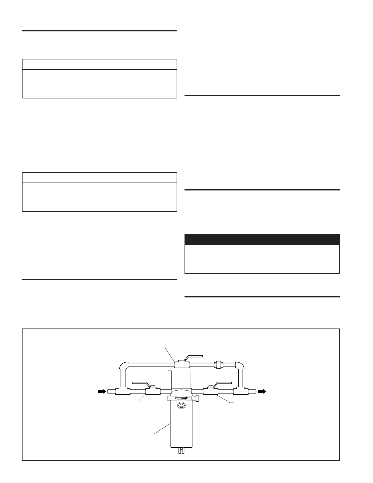
Install bypass piping around dryer to facilitate servicing (Ref-
3.
erence Figure 2).
FIGURE 2 RECOMMENDED INSTALLATION
BYPASS VALVE
INLET
PORT B
INLET
SHUTOFF
VALVE
D-2
SHUT DOWN
Close dryer inlet and outlet shutoff valves. Open bypass valve.
1.
Slowly open drain valve to depressurize dryer.
2.
OUTLET
PORT A
OUTLET
SHUTOFF
VALVE
PAGE 2
Page 3
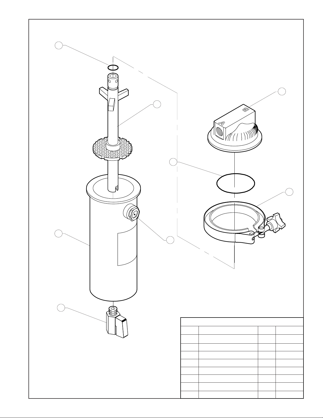
FIGURE 3 REPLACEMENT PARTS
4
1
5
2
3
6
7
8
REPLACEMENT PARTS
ITEM PART DESCRIPTION QTY PART NO.
1 DRYER HEAD 1 201-00050
2 HOUSING O-RING 1 475-002 3 5
3 HOUSING CLAMP 1 471-00100
4 STE M O-RING 1 4 75 -0 0 2 1 0
5 STEM & GRID ASSEMBLY 1 180-00001
6 DRYER BOWL 1 201-02000
7 SIGHT GLAS S 1 551-00400
8 1/4" NP T BALL VALVE 1 2 90-000 11
PAGE 3
Page 4
MAINTENANCE
Drain dryer at least once during each 8-hour shift.
1.
Check desiccant bed weekly. Inspect the desiccant bed level
2.
by looking through the sight glass window (Reference Figure
1). More tablets must be added when bed level falls below low
level (Reference Figure 1). Use Van Air Dry-O-Lite Desiccant
P/N: 33-0313 (50 lb pail).
WARNING
DO NOT OPERATE DAMAGED OR LEAKING DRYER, REMOVE
FROM SERVICE IMMEDIATELY.
TROUBLE SHOOTING
CONDITION POTENTIAL
Decreased
performance
or increased
desiccant
usage.
Liquid
downstream
of dryer.
Decreased
performance,
low
desiccant
usage.
CAUSE
High inlet a ir
temperatures.
High ambient
temperatures.
Improper
draining.
Bypass valve
ope n or faulty
Low or no
desiccant in
dryer.
Contaminated
desiccant bed.
RECOMMENDATION
Check the aftercooler performance to make sure the airstream temperature is under 100°F. Make sure that the aftercooler was properly
sized and installed. Check the aftercooler operation manual for further details.
If an aircooler was not installed, one may be required.
Check the location of the dryer for changes in ambient temperatures. If a piece of equipment or piping installed near the dryer is creating
the increase in temperature, relocate the dryer or equipment if possible. If relocation is not possible, correct the increased ambient
temperature through insulation or another method.
Drain dryer at least once every 8 hours of operation.
Check the drain valve and piping for clogs. Repair or replace faulty valves. Clean any clogged piping. If freezing occurs, raise ambient
temperature or wrap piping and dryer with heat tracing and/or insulation.
Inspect se parator. Remove water wi th better sep aration.
If a separator was not installed, one may be required.
Check the compressor capacity or air usage vs. the dryer rating.
Check the dryer bypass valve. Replace or repair if necessary.
Check dryer desiccant bed level. Fill dryer as needed (Reference Figure 1).
Dryer can operate with normal amounts of compressor lubricant. If compressor manufacturer's recommended lubrication rate is exceeded,
the desiccant bed can become contaminated with lubricant.
Periodically check the desiccant bed. If tablets are discolored (deep yellow or brown), the bed is contaminated. If bed has become
contaminated, remove and discard desiccant, clean out dryer and install new desiccant. Remedy contamination problem before opening
bypass piping.
Check the compressor for proper operation. The compressor may be worn or over lubricated. Check the compressor operator's manual.
Check the atmospheric air near the compressor air intake. Heavy concentrations of acid fumes or smoke and dust will cause
contamination. Install a filter on the compressor intake. If it is not possible to reduce the amount of lubricants in the air system, i ns tall a
separator and/or coalescing filter upstream of the dryer.
WARNING
IF UNIT IS NOT DRAINED REGULARLY, FLOODING OF
DRYER MAY OCCUR. IF FLOODING OCCURS, ACCUMULATED LIQUID MAY CARRY OVER AND RESULT IN DAMAGE TO DOWNSTREAM EQUIPMENT.
PAGE 4
2950 Mechanic Street
Lake City, PA 16423-2095
Phone: 814-774-2631
Fax: 814-774-3482
www.vanairsystems.com
 Loading...