

Page 1
JANUARY 2005
P/N 32-0271 rev C
INSTALLATION, OPERATION, & MAINTENANCE INSTRUCTIONS
FOR
SINGLE TOWER
COMPRESSED AIR DRYER
MODELS
D-4 & D-8
WARNING
DO NOT REMOVE, REPAIR, OR REPLACE ANY ITEM ON THE DRYER WHILE IT IS UNDER PRESSURE. DEPRESSURIZE
THE DRYER COMPLETELY BEFORE STARTING INSTALLATION AND/OR MAINTENANCE PROCEDURES. SERIOUS
PERSONAL INJURY MAY RESULT IF THESE SAFETY RULES ARE NOT FOLLOWED.
DO NOT OPERATE THIS PRESSURE VESSEL ABOVE MAXIMUM WORKING PRESSURE (MWP) AT MAXIMUM
OPERATING TEMPERATURE (OF) AS SHOWN ON THE ASME DATA PLATE.
THIS ASME CODE VESSEL MUST BE PROTECTED BY A PRESSURE RELIEF VALVE. Refer to OSHA 1910.169 Par.
b, Sub. Par (3) and ASME Boiler and Pressure Vessel Code, Section VIII, Division 1, UG-125 through UG-136. Also
check government regulations, i.e., state and local codes.
DO NOT WELD, GRIND, OR SAND VESSEL, OR IT WILL NOT BE SAFE TO OPERATE. (Note: Any alteration to the
vessel will void the ASME Code Certification and the warranty.)
ANY DAMAGE TO THE VESSEL CAN MAKE IT UNSAFE. INSPECT OUTSIDE AND INSIDE OF VESSELS
REGULARLY FOR BULGES, CORROSION, DENTS, GOUGES, LEAKS OR SIGNS OF FIRE. IF DAMAGED, TAKE OUT
OF SERVICE IMMEDIATELY AND NOTIFY YOUR CERTIFYING AUTHORITY.
USE THE PROPER SAFETY RULES FOR THE GAS BEING PROCESSED.
DO NOT REMOVE THE FILL PORT UNTIL ALL AIR PRESSURE IS OUT OF THE VESSEL.
PAGE 1
Page 2
SECTION 1 INTRODUCTION
1.0 PURPOSE OF OPERATION
The purpose of installing a Van Air single tower dryer in a
compressed air system is to remove the water vapor (humidity) which
has been drawn into the system at the compressor intake. The Van
Air process dries the air as it flows through the vessel, which is filled
with a special drying agent. The dryer operates automatically. There
are no moving parts and no external source of power is required. If
an automatic drain is installed, a power source is required only to
operate the valve.
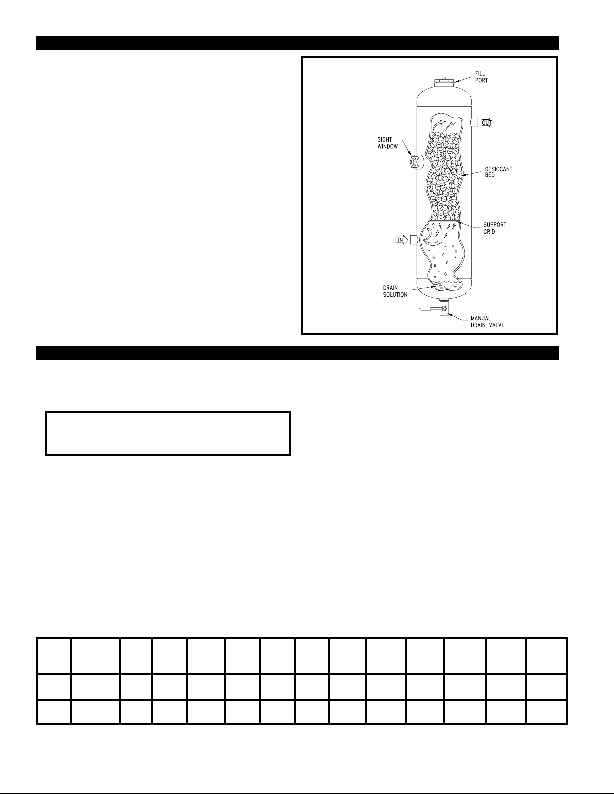
The wet air enters the centrally located inlet which channels the flow
into the lower portion of the dryer. Liquid water and solid particles are
separated by gravity and fall to the bottom of the vessel.
The process air moves upward through the bed of desiccant tablets
which attract and absorb the moisture from the air before it flows
through the dryer outlet. The tablets dissolve gradually as they
absorb the moisture.
The tablets create a structured bed that does not crush under its own
weight. In the bed of an operating dryer, the lower tablets are
consumed first.
The tablets in the top portion serve as a reserve supply. When the
reserve supply is depleted, the dryer must be refilled to maintain
performance.
The solution, which consists of dissolved desiccant and water, falls
into the claim area at the bottom of the vessel. The dryer must be
drained at least once a shift to remove the accumulated solution.
FIGURE 1 DRYER DETAILS
SECTION 2 INSTALLATION
2.1 LOCATION
The ability of a dryer to provide dry compressed air depends on the
correct location of the unit. Inlet air temperature and pressure are the
keys to selecting the proper location.
area. Make sure that the dryer is not exposed to ambient temperatures
below the minimum design temperature stamped on the vessel data
tag. When the dryer will be exposed to the direct rays of the sun,
install a sun shield to protect it (i.e. a roof).
ALWAYS PROCESS AIR THROUGH THE DRYER AT THE
LOWEST POSSIBLE TEMPERATURE AND THE HIGHEST
PRACTICAL PRESSURE.
IMPORTANT
2.1-A INLET AIR TEMPERATURE
The dew point of the outlet air is directly related to the inlet air
temperature and the type of desiccant being used. The lower the inlet
temperature, the lower the dew point of the outlet air. Determine the
lowest ambient temperature where the compressed air is used or
where the lines are located. If you are using DRY-O-LITE or 10BF
desiccants, do not exceed 100oF inlet air temperature. If you are
using SP desiccant, do not exceed 80oF inlet air temperature.
2.1-B AFTERCOOLING
Air discharged by the compressor is extremely hot (from 150oF to
350oF). An aftercooler, finned tubing or extended run of piping will
usually be necessary to reduce the inlet air temperature to the dryer.
2.1-C OUTDOOR AIR USAGE
If some or all of the air supplied by the Van Air single tower dryer will
be used outdoors, install the dryer outdoors in the coolest possible
FIGURE 2 MAXIMUM CAPACITIES -SCFM (Nm3/hr)
MAXIMUM
3
4.8
15
24.1
40 PSIG
2.8 Bar
4.8
7.7
24
38.6
MODEL
NO.
D 4
D 8
WORKING
PRESSURE
250 PSIG
250 PSIG
5 PSIG
0.3 Bar
1.7
2.7
9
14.5
10 PSIG
0.7 Bar
2.2
3.5
11
17.7
20 PSIG
1.4 Bar
60 PSIG
4.1 Bar
6.5
10.5
33
53
2.1-D INDOOR AIR USAGE
If all of the air from the dryer will be used indoors where temperatures
remain within a fixed range, locate the dryer in the coolest indoor
area. When air equipment or piping is located in an air conditioned
area, install the dryer in the coolest area--usually the air conditioned
area.
2.1-E AIR RECEIVER
The Van Air single tower dryer should be located where it will be
provided with the coolest inlet temperature. If the receiver is located
in an area where the ambient temperature is lower than the outlet air
from the aftercooler, locate the dryer downstream of the receiver to
allow additional cooling of the air before it enters the dryer. (Exception:
In systems where usage creates sudden demands on the air supply,
locate dryer before the receiver to minimize air surges through the
dryer.) If the ambient temperature around the receiver is higher than
the outlet air temperature from the aftercooler, locate the dryer
between the aftercooler and the receiver.
2.1-F SPECIAL EQUIPMENT INSTALLATION
If the Van Air Dryer is being installed on a branch line to protect a
specific piece of air-operated equipment, locate the dryer on the high
pressure side of any pressure regulators.
80 PSIG
5.5 Bar
8.3
13.3
41
66
90 PSIG
6.2 Bar
9.1
14.6
46
74
100 PSIG
6.9 Bar
10
16
50
80
125 PSIG
8.6 Bar
12.2
19.6
61
98
150 PSIG
10.3 Bar
14.4
23.2
200 PSIG
13.8 Bar
18.7
30.1
72
116
94
151
250 PSIG
17.2 Bar
23.1
37.1
115
185
PAGE 2
Page 3
SECTION 2 INSTALLATION
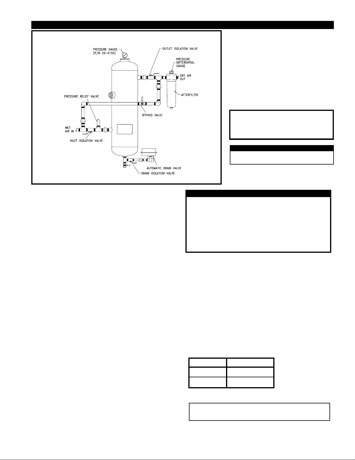
FIGURE 3 RECOMMENDED INSTALLATION DRAWING
NOTE:
ITEMS CALLED OUT IN THIS DRAWING
ARE NOT SUPPLIED WITH THE DRYER.
REFERENCE FIGURES 1 & 4 FOR ITEMS
INCLUDED WITH DRYER.
2.1-G OPERATING PRESSURE
More air can be processed through the dryer at higher pressures.
Locate the dryer at the highest practical pressure, but do not exceed
the maximum rated working pressure of the dryer. Refer to FIGURE
2 located on page 3 for the maximum working pressure for your dryer.
2.2-D MANUAL DRAIN VALVE
The drain port is a 1/2" NPT tapped hole in the
center of the vessel bottom head.
Shipped separately with the dryer is (1) 1/2" NPT
close nipple and (1) 1/2" NPT brass ball valve.
Install the nipple and valve into the drain port.
The drain of the dryer can be remotely piped away
from the dryer. Make sure that the line is vented to
atmospheric pressure. Any remote drain piping
should be of the same size and on the same level or
lower than the drain valve.
IMPORTANT
The drain solution may contain lubricants.
Comply with all applicable regulations
concerning the disposal of these chemicals
CAUTION
DO NOT CONNECT THE DRAIN TO A
PRESSURIZED LINE.
CAUTION
THE DRAIN SOLUTION WILL BE DISCHARGED UNDER LINE
PRESSURE. POINTING THE DRAIN IN THE DIRECTION OF
PEOPLE AND EQUIPMENT MAY RESULT IN INJURY AND
DAMAGE.
2.2 PIPING AND ANCILLARY EQUIPMENT
Locate the dryer in the proper location as explained in the previous
section.
If the dryer is being installed in an existing piping system, make sure that
the pipe is free of scale and rust.
The dryer will be supported by the piping system. Adequate pipe
supports must be used to prevent damage to the pipeline and dryer.
2.2-A INLET AND BYPASS PIPING
Using Figure 3 as a reference, make the necessary piping connections
into the dryer.
Inlet and outlet isolation valves should be installed on the dryer.
These valves will aid in the start up and shutdown of the dryer. The
inlet isolation valve should be mounted before the pressure relief
valve. The outlet isolation valve should be installed on the dryer outlet.
A bypass valve and piping should also be installed. This will allow the
dryer to be taken off stream without interrupting the air system.
2.2-B OPTIONAL PRESSURE RELIEF VALVE (p/n 14-2213)
A pressure relief valve should be installed to conform to OSHA safety
standards. Refer to OSHA Standard Section 1910.169, paragraph
b, subparagraph 3 and any other federal, state or local codes
concerning pressure vessels.
2.2-C OPTIONAL PRESSURE GAUGE (p/n 29-0150)
An optional pressure gauge is available for this dryer.
DO NOT INSTALL A FLOAT TYPE (OTHER THAN THE PDV-500)
OR SOLENOID TYPE DRAIN ON THE DRYER. THE DRAIN
SOLUTION WILL CAUSE THESE TYPES OF DRAINS TO FAIL,
THUS RESULTING IN FLOODING OF THE DRYER.
2.2-E OPTIONAL AUTOMATIC DRAIN VALVE (p/n 39-2211121)
The MDV-400I drain valve is recommended. Use model PDV-500 (PN
39-0283) for pneumatic applications. Contact your local VAN AIR
representative to order.
Complete the automatic drain valve installation as outlined in the
instructions supplied with the drain. The drain line can be remotely
piped, follow the precautions as outlined previously.
2.2-F AFTERFILTER
The installation of an afterfilter prevents any accidental flow of materials
from the dryer into the downstream piping.
The afterfilter can be installed before or after the outlet isolation valve.
If the afterfilter is installed before the isolation valve, the filter can be
isolated from the air system when the dryer is isolated for maintenance.
Contact your local VAN AIR representative to order.
DRYER FILTER
D-4 F200-15-1/4-B
D-8 F200-55-1/2-B
2.2-G DESICCANT INSTALLATION
IMPORTANT
This dryer was shipped WITHOUT the desiccant installed. The
desiccant MUST BE INSTALLED before using the dryer
The procedures for filling the dryer with desiccant are outlined in Section
4.4 of this manual.
PAGE 3
Page 4
SECTION 2 INSTALLATION
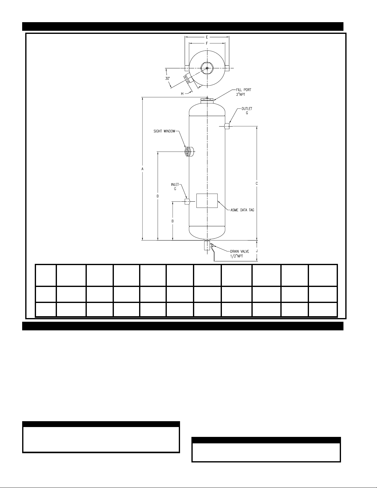
FIGURE 4 DRYER DIMENSIONAL DETAILS
MODEL
NO.
D 4
D 8
APPROX
WEIGHT
w/o Desiccant
30 LBS
60 LBS
A
27-3/4"
704.9mm
35-1/16"
890.6mm
B
6-15/16"
176.2mm
9-1/2"
241.3mm
C
22-7/16"
569.9mm
28"
711.2mm
D
19-5/16"
490.5mm
21-3/4"
552.5mm
E
6-1/2"
165.1mm
10-5/8"
269.9mm
F
4-1/2"
114.3mm
8-5/8"
219.1mm
G
3/4" NPT
3/4" NPT
H
1-3/8"
34.9mm
1-9/16"
39.7mm
J
5-1/8"
130.2mm
5-1/8"
130.2mm
SECTION 3 OPERATION
3.1 START UP PROCEDURES
Close the inlet isolation valve and open the bypass valve.
Open the outlet isolation valve SLOWLY and allow some air to bleed
through the drain valve; then close the drain valve. When the dryer
reaches normal operating pressure, SLOWLY turn the inlet valve to full
open position; then close the bypass valve.
If the vessel was installed without the bypass or isolation valves,
SLOWLY pressurize the air system. Allow some air to bleed through the
drain valve. Once the vessel starts to pressurize, the drain valve can be
closed.
Close the bypass valve, the dryer is now on stream.
CAUTION
Make sure that the dryer is not subjected to sudden flow
surges. Always open the valves slowly to permit gradual
equalization of pressure between the dryer and the air supply
lines.
PAGE 4
3.2 OPERATING THE DRYER
The simple design of the single tower dryer allows for easy
operation.
The dryer requires two procedures to ensure peak performance.
3.2-A DAILY DRAINING
The accumulated solution in the bottom of the dryer should be
drained at least once for every 8 hours of operation. Depending
upon actual operating conditions, the dryer may require draining
on a more frequent basis.
If an automatic ball valve type drain valve was installed on the
dryer, set the time cycle for every 4 to 8 hours. The manual drain
valve must be opened at least once every 4 to 8 hours to drain the
dryer.
CAUTION
If the dryer is not drained regularly, it may become
flooded. Accumulated liquid may enter the air system
and cause damage to downstream equipment.
Page 5
SECTION 3 OPERATION
On a new installation, continue to drain all downstream traps for
several days (or until no water is evident) after dryer is installed. This
period is required to dry out any accumulated water in the compressed air system. Once the water is removed, the downstream
traps should not need to be drained again.
Reference Section 4.4 for estimated consumption rates and
refilling instructions.
IMPORTANT
Use VAN AIR desiccant only. Filling dryer with any other
material will void the warranty.
3.2-B REFILLING THE DRYER WITH DESICCANT
During the VAN AIR drying process, the desiccant tablets dissolve
slowly. More tablets must be added to the supply when the top of the
bed drops to the sight window level (minimum level). Reference
FIGURE 5.
The desiccant consumption rate is dependent upon several factors,
such as inlet temperature, flow, pressure and the type of desiccant
being used . With average conditions, the desiccant will usually need
to be added only two to three times per year when the dryer is
operating one shift per day. However, until the actual usage rate is
determined, check the bed level monthly.
3.3 USING THE SIGHT WINDOW
WARNING
IF SIGHT WINDOW IS DAMAGED IN ANY WAY, REPLACE IT
IMMEDIATELY WITH VAN AIR PART NO. 26-0104 only.
REFERENCE SECTION 4.3.
To check the level of the desiccant bed, look into the sight window.
When the top of the desiccant bed is level with the sight window, the
desiccant supply has dropped to the minimum level. The bed must be
replenished to raise the bed level to the maximum level.
SECTION 4 MAINTENANCE
4.1 DAILY PROCEDURES
After every 8 hour period of operation, drain accumulated solution from
the bottom of dryer. Open manual drain valve and allow the solution to
discharge from the dryer; then close the manual drain valve securely.
4.2 MONTHLY PROCEDURES
Check the level of the desiccant bed by looking into the sight window.
If the top of the desiccant bed is level with the sight window, the
desiccant bed must be replenished.
Check the operation of all equipment installed before and after the
dryer.
Check the afterfilter element condition. If the pressure differential
across the filter is high (6 to 9 PSID), replace the element.
4.4 ADDITION OF DESICCANT
WARNING
DO NOT REMOVE, REPAIR, OR REPLACE ANY ITEM ON THE
DRYER WHILE IT IS UNDER PRESSURE. DEPRESSURIZE THE
DRYER COMPLETELY BEFORE STARTING INSTALLATION AND/
OR MAINTENANCE PROCEDURES.
Open the bypass valve. Close the dryer inlet and outlet isolation valves.
If the bypass and inlet and outlet isolation valves were not installed, shut
down the air system.
Open the drain valve and allow the dryer to depressurize completely.
Remove the fill port.
Inspect the hatch cover for signs of corrosion and/or leaks. Replace
the cover and/or gasket if necessary.
4.3 REPLACING THE SIGHT WINDOW (P/N 26-0104)
WARNING
DEPRESSURIZE DRYER COMPLETELY BEFORE
REMOVING THE SIGHT WINDOW.
Open the bypass valve. Close the dryer inlet and outlet isolation valves.
If the bypass and inlet and outlet isolation valves were not installed,
shutdown the air system.
Using a pipe wrench, unthread the old sight window. Remove all pipe
sealant, rust or dirt from the coupling.
Apply a layer of pipe sealant to the threads of the new sight window.
DO NOT USE TEFLON TAPE. Tape may prevent the sight window
from threading into the coupling far enough.
Add the amount of desiccant tablets required to raise the supply to the
normal operating level or to maximum level (see FIGURE 5); then level
off the tablet bed.
Replace and tighten the fill port.
PAGE 5
Page 6
SECTION 4 MAINTENANCE
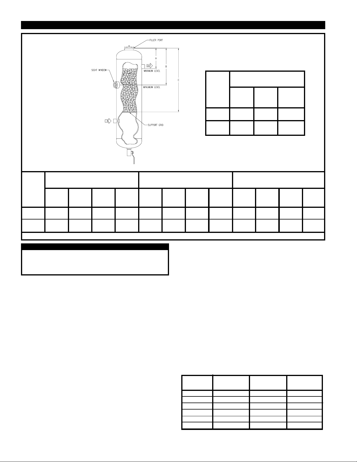
FIGURE 5 BED LEVEL DETAIL
BED DIMENSIONS
INCHES (centimeters)
B
MIN.
Level
7-11/16"
(19.53)
12-1/2"
(31.75)
C
Total
Depth
17-11/16"
(44.93)
21-11/16"
(55.09)
MODEL
D4
D8
A
MAX.
Level
5-1/4"
(13.33)
6-15/16"
(17.62)
DRY-O-LITE QUANTITY*
POUNDS (kilograms)
MIN to
Lbs./In
D4
D8
of bed**
0.55
0.25
2.32
1.05
MODEL
* Amounts are pounds (kilograms) required to fill dryer to levels indicated. ** Amounts in italics are kilograms per centimeter of bed depth.
Make sure that the desiccant does not cover the screen on the
outlet pipe.
Do NOT overfill the vessel.
Start up the dryer following the procedures in Section 3.1.
MIN.
Level
5.53
2.51
21.61
9.80
MAX
Level
6.86
3.11
34.44
15.62
CAUTION
MAX
Level
1.33
0.60
12.83
5.82
Lbs./In
of bed**
0.405
0.18
1.70
0.77
4.4-A BED LEVEL GUIDE
To determine the supply of desiccant in the dryer, insert a
measuring stick through the fill port until it reaches the top of the
desiccant bed; dimensions in FIGURE 5 are calculated from the fill
port to levels indicated on the drawing. (NOTE: Dimensions are
approximate and are intended as a general guide only.)
4.4-B DESICCANT USAGE GUIDE
The chemical and physical characteristics of Van Air desiccant
contribute to its effectiveness and economy.
The DESICCANT CONSUMPTION RATE should be used as a guide
to estimate the usage of desiccant your installation will require. The
formula is based on an annual usage rate of one shift per day, 5 days
per week and 50 weeks per year or 2,000 operating hours per year.
The figure is an average and may vary depending upon your actual
conditions (i.e. 24 hour operation, higher inlet temperature, excessive
liquid water content and/or contaminants.)
SP QUANTITY*
POUNDS (kilograms)
MIN.
Level
4.05
1.84
15.84
7.19
MAX
Level
5.02
2.28
25.24
11.45
DESICCANT CONSUMPTION
(Based upon 1 shift for a one year period @ 100 psig inlet pressure and
75oF inlet temperature, 100% RH.)
To use the chart, first determine the SCFM that is being processed
through the dryer. Locate the nearest flow rate listed on the chart
and interpolate as necessary.
The consumption rate is proportional to the moisture loading. Each
20oF change in inlet temperature changes the moisture loading by a
factor of nearly 2:1.
The quantity shown in the consumption rate chart is NOT the
quantity that must be added to the dryer at one time. The bed level
should be maintained at least to the minimum level at all times to
ensure optimum drying capabilities. The consumption rate is an
approximation of how much desiccant will be added over a period of
one year.
The desiccant bed should be filled approximately 2 to 3 times a year.
FLOW
SCFM
10
20
40
50
75
100
MIN to
MAX
Level
0.97
0.44
9.40
4.26
DRY-O-LITE
LBS/YEAR
13.2
26.4
52.8
66.0
99.0
132.0
Lbs./In
of bed**
0.48
0.22
2.01
0.91
10 BF QUANTITY*
POUNDS (kilograms)
MIN.
Level
4.8
2.18
18.72
8.49
SP
LBS/YEAR
66.5
133
266
332.5
498.8
665.0
MAX
Level
5.96
2.70
29.84
13.54
MIN to
MAX
Level
1.16
0.53
11.12
5.04
10 BF
LBS/YEAR
57.6
115.2
230.4
288.0
432.0
576.0
PAGE 6
Page 7
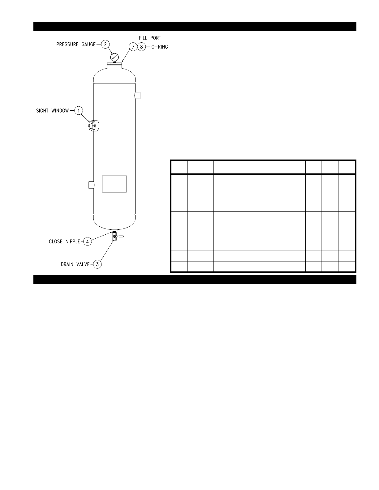
SECTION 5 REPLACEMENT PARTS
D4
ITEM
1
2
3
4
5
6
7
8
PART NO.
26-0104
29-0150
14-0450
12-0520
33-0313
33-0311
33-0205
33-0232
14-2213
14-2188
26-10264
DESCRIPTION
Sight Window
Pressure gauge (0-200 PSIG) only
Manual Drain Valve 1/2" NPT
Close nipple 1/2" NPT
DESICCANT
DRY-O-LITE Desiccant, 50 LB PAIL
DRY-O-LITE Desiccant, 50 LB BAG
SP Desiccant, 50 LB BAG
10BF Desiccant, 25 LB PAIL
Pressure Relief Valve (not shown)
Fill Port
O-Ring
QTY
1
1
1
1
1
1
1
1
1
1
1
SECTION 6 TROUBLESHOOTING
1. DECREASED PERFORMANCE OR INCREASED
DESICCANT USAGE.
High inlet air temperatures.
Check the aftercooler performance. Make sure that the
aftercooler was properly sized and installed. Check the aftercooler
operation manual for further details.
If an aftercooler was not installed, one may be required.
Check the compressor capacity or air usage vs. the dryer rating.
Desiccant bed below required level.
Check the desiccant bed level. The level should be checked at
least once a month. The usage of desiccant will vary with the
operating conditions and the type of desicccant being used. The
dryer will require more desiccant during the warmer months of the
year.
Desiccant quantities and filling procedures are outlined in Section
4.4 of this manual.
2. LIQUID DOWNSTREAM OF THE DRYER.
Was a different compressor installed?
High ambient temperatures.
Check the location of the dryer for changes in ambient temperatures.
Was the dryer moved to a different location?
Improper draining. The dryer may be flooded.
The dryer must be drained at least once for every 8 hours of
operation.
Check the drain valve(s) and piping for clogs. Repair or replace
faulty valves. If the piping is clogged, it must be cleared.
D8
QTY
1
1
1
1
1
1
1
1
1
1
1
Was a piece of equipment or piping installed near the dryer that
caused an increase in ambient temperatures? Relocate the dryer
or equipment if possible. If relocation is not possible, correct the
ambient temperature.
Dryer overloaded.
Check the flow through the dryer. Check the flow at peak usage
periods. Have the flow requirements of the system increased?
Was the dryer properly sized for the actual operating conditions?
Check the capacity of the dryer for the system conditions. If the
system requirements exceed the dryer's capability, a larger dryer
must be installed.
If the dryer is installed outdoors where ambient temperatures fall
below freezing, the drain line and valve(s) may freeze. If ambient
temperatures fall below freezing, the drain line can be wrapped
with heat tracing and/or insulation to prevent freezing.
If maintaining the required draining schedule is a problem, an
automatic ball type drain valve should be installed. Reference
Section 2.2-E in this manual for installation instructions.
IMPORTANT: Never install a float type (other than Van Air model
PDV-500) or solenoid type drain valve on this dryer.
PAGE 7
Page 8
SECTION 6 TROUBLESHOOTING
Bypass valve open or faulty.
Check the dryer bypass valve. It might be faulty or open allowing
untreated air to enter the air system.
Low or no desiccant in the dryer.
Check the dryer desiccant bed level. Reference Section 4.4 for
filling quantities and procedures.
3. DECREASED PERFORMANCE, low desiccant usage.
The desiccant bed may be contaminated.
The dryer will tolerate normal amounts of compressor lubricant. If
the compressor manufacturer's recommended lubrication rate is
exceeded, the desiccant bed can become contaminated with
compressor lubricants.
If the bed has become contaminated, it can be flushed with an
adequate supply of water. Depending upon the severity of
contamination, it might be necessary to completely flush the entire
bed from the dryer and replace it with new desiccant.
Check the compressor for proper operation. The compressor
might be worn or over lubricated. Check the compressor
operator's manual and correct.
Check the atmospheric air near the compressor air intake. Heavy
concentrations of acid fumes or smoke and dust will cause
contamination if they are drawn into the air system. Check or
install a filter on the compressor intake.
Periodically check the desiccant bed. If the tablets are discolored
(deep yellow or brown), the bed may be contaminated.
If it is not possible to reduce the amount of lubricants in the air
system, a separator and/or coalescing filter should be installed
before the dryer.
If the check list in this section does not remedy the problem, consult your local VAN AIR distributor or call the VAN AIR factory.
MAKING COMPRESSED AIR AND GAS WORK BETTER SINCE 1944.
PAGE 8
2950 Mechanic Street
Lake City, PA 16423-2095
Phone: 814/774-2631
Fax: 814/774-3482
 Loading...