

Page 1
P/N 32-0233 REVA
INSTALLATION, OPERATION, & MAINTENANCE INSTRUCTIONS
FOR
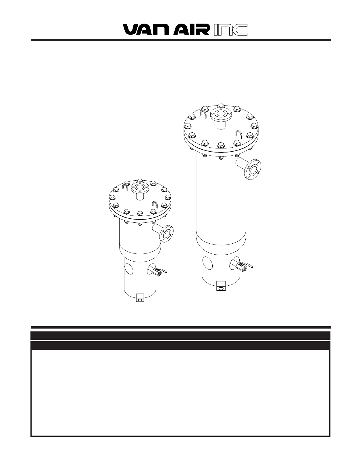
MIST ELIMINATOR
VME-125 through VME-10,000
AUGUST 1998
SECTION 1 SAFETY
WARNING
DO NOT REMOVE, REPAIR, OR REPLACE ANY ITEM ON THE
VESSEL WHILE IT IS UNDER PRESSURE. DEPRESSURIZE THE
VESSEL COMPLETELY BEFORE ANY MAINTENANCE
PROCEDURES. SERIOUS PERSONAL INJURY MAY RESULT IF
THESE SAFETY RULES ARE NOT FOLLOWED.
DO NOT OPERATE THIS PRESSURE VESSEL ABOVE MAXIMUM
WORKING PRESSURE (MWP) AT MAXIMUM OPERATING
TEMPERATURE (OF) AS SHOWN ON THE ASME DATA PLATE.
THIS ASME CODE VESSEL MUST BE PROTECTED BY A
PRESSURE RELIEF VALVE. Refer to OSHA 1910.169 Par. b,
Sub. Par (3) and ASME Boiler and Pressure Vessel Code,
Section VIII, Division 1, UG-125 through UG-136. Also check
government regulations, i.e., state and local codes.
PRINTED IN THE U.S.A. © 1998 VAN AIR SYSTEMS INC. 2950 MECHANIC STREET, LAKE CITY, PA 16423 PAGE 1
DO NOT WELD, GRIND, OR SAND VESSEL, OR IT WILL NOT
BE SAFE TO OPERATE. (Note: Any alteration to the vessel will
void the ASME Code Certification and the warranty.)
ANY DAMAGE TO THE VESSEL CAN MAKE IT UNSAFE.
INSPECT OUTSIDE AND INSIDE OF VESSELS REGULARLY
FOR BULGES, CORROSION, DENTS, GOUGES, LEAKS OR
SIGNS OF FIRE. IF DAMAGED, TAKE OUT OF SERVICE
IMMEDIATELY AND NOTIFY YOUR CERTIFYING AUTHORITY.
USE THE PROPER SAFETY RULES FOR THE GAS BEING
PROCESSED.
Page 2
SECTION 2 HANDLING
2.1 HANDLING INSTRUCTIONS
If the unit is to be lifted by an overhead device, attach the lifting
chains or cables to the vessel lifting lugs on the top head.
must be free of standing water and mud. If the location is outdoors,
a paved surface is recommended.
Models VME-5000 through VME-10000 are shipped without the
elements installed. These elements are shipped separately in
wooden crates. Use extreme caution when unloading or moving the
elements with fork lifts. Always lift the crate from below the crate
supports to prevent the element from being pierced or torn.
2.2 STORAGE INSTRUCTIONS
If the unit is to be placed in storage before it is installed, the location
should be a clean, dry place. The ideal place to store the unit is
indoors. The location should be free from corrosive gasses and
extreme humidity. These conditions will cause damage to the unit.
The unit should be covered with a tarpaulin to keep the it clean.
If the unit is to be stored outdoors, it MUST BE covered completely
to prevent rain or snow from accumulating on the unit. The location
When storing the elements, they should be protected to prevent
them from being contaminated or saturated with water. Provisions
must be taken to prevent vermin from entering the elements and
using the element fibers for nesting material.
The large crated elements should be stored horizontally. Do not
stack them more than 4 crates high.
2.3 EQUIPMENT CHECK
Inspect the vessel and any elements for any damage that may have
occurred during shipment. Check the packing list to insure that all
items shipped with the unit are present.
IF EQUIPMENT HAS BEEN DAMAGED DURING SHIPMENT:
(1) NOTIFY CARRIER IMMEDIATELY.
(2) DO NOT OPERATE BEFORE CONSULTING FACTORY.
SECTION 3 SPECIFICATIONS AND DIMENSIONS
3.1 SPECIFICATIONS
VESSEL CONSTRUCTION
• Designed and manufactured to the ASME code plus current
addenda.
• Models VME-125 through VME-500 stamped "UM" symbol.
• Models VME-1250 through VME-10000 stamped "U" symbol.
• All models designed with a vessel corrosion allowance of
0.0625".
• Exterior primed white enamel finish.
• All flanged bolt holes oriented to straddle centerlines.
VESSEL WEIGHT (without elements)
VME-125 ........ 420 LBS
VME-250 ........ 440 LBS
VME-500 ........ 480 LBS
VME-850 ....... 525 LBS
VME-1250 ...... 710 LBS
VME-1500 ...... 820 LBS
VME-2000 ...... 1040 LBS
VME-2500 ...... 1170 LBS
VME-3000 ...... 1300 LBS
VME-7500 ...... 2500 LBS
VME-10000.... 2720 LBS
NOTE: Models VME-125 through VME-3000 are shipped with the elements
factory installed.
ELEMENT WEIGHTS
EVME-125 ..... 20 LBS
EVME-250 ..... 20 LBS
EVME-500 ..... 35 LBS
EVME-850 ..... 50 LBS
EVME-1250 ... 60 LBS
EVME-1500 ... 70 LBS
EVME-2000 ... 90 LBS
EVME-2500 ... 120 LBS
EVME-3000 ... 150 LBS
EVME-5000 ... 235 LBS
EVME-7500 ... 400 LBS
EVME-10000 . 460 LBS
RATED FLOW AT 100 PSIG, 100OF
VME-125 ........ 125 SCFM
VME-250 ........ 250 SCFM
VME-500 ........ 500 SCFM
VME-850 ....... 850 SCFM
VME-1250 ...... 1250 SCFM
VME-1500 ...... 1500 SCFM
VME-2000 ...... 2000 SCFM
VME-2500 ...... 2500 SCFM
VME-3000 ...... 3000 SCFM
VME-5000 ...... 5000 SCFM
VME-7500 ...... 7500 SCFM
VME-10000.... 10000 SCFM
MULTIPLIERS FOR PRESSURES OTHER THAN 100 PSIG
Pressure 50 60 70 80 90 100 110 120 130 140 150
Multiplier .56 .65 .74 .83 .91 1.00 1.09 1.17 1.26 1.35 1.44
MULTIPLIERS FOR TEMPERATURES OTHER THAN 100
Temp. 50 75 100 125 150 175 200 250 300
Multiplier 1.10 1.05 1.00 .96 .92 .88 .85 .79 .74
ELEMENT PRESSURE DROP
• Element pressure drop will be less than 1 PSID at initial start up
and throughout life.
• Element should be replaced when pressure drop reaches 3 PSID
ELEMENT EFFICIENCY
• 100% efficiency for particles over 3 MICRONS
• 99.5% efficiency for particles 3 MICRONS and less
MAXIMUM MIST CARRYOVER
• Mist carryover < 1 PPM, assuming an inlet loading of < 200 PPM
at 100oF inlet temperature.
O
F
OPERATING PRESSURE RANGE (all models)
Minimum ........ 50 PSIG Maximum ............... 150 PSIG
OPERATING TEMPERATURE (all models)
Maximum ....... 300
PAGE 2 © 1998 VAN AIR SYSTEMS INC. 2950 MECHANIC STREET, LAKE CITY, PA 16423 PRINTED IN THE U.S.A.
O
F
Page 3
SECTION 3 SPECIFICATIONS AND DIMENSIONS
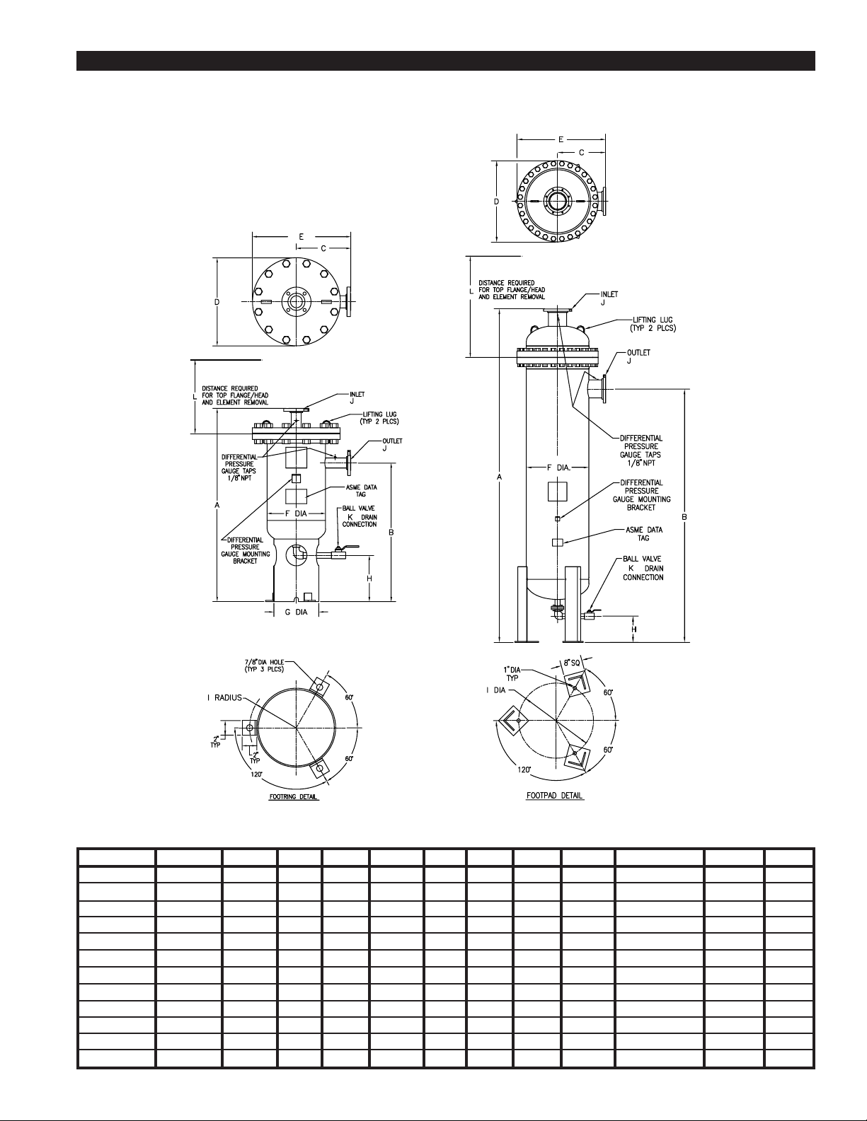
3.2 DIMENSIONS AND COMPONENT LAYOUT for VME-125 through VME-10000
MODELS VME-125 through VME-3000
MODEL A B C D E F G H I J K L
VME-125 42-1/8" 29" 13" 21" 23-1/2" 14" 10-3/4" 11" 6-3/8" 2" RF FLG 1" NPT 23"
VME-250 46-1/8" 33" 13" 21" 23-1/2" 14" 10-3/4" 11" 6-3/8" 2" RF FLG 1" NPT 27"
VME-500 58-1/8" 45" 13" 21" 23-1/2" 14" 10-3/4" 11" 6-3/8" 2-1/2" RF FLG 1" NPT 39"
VME-850 72-1/8" 59" 13" 21" 23-1/2" 14" 10-3/4" 11" 6-3/8" 2-1/2" RF FLG 1" NPT 39"
VME-1250 78-3/8" 63-1/4" 14" 23" 25-3/4" 16" 12-3/4" 10-1/2" 7-3/8" 4" RF FLG 1" NPT 59"
VME-1500 79-3/4" 64-5/8" 15" 25" 27-1/2" 18" 12-3/4" 10-3/8" 7-3/8" 4" RF FLG 1" NPT 59"
VME-2000 71-5/8" 55-1/8" 18" 32" 34" 24" 16" 9" 9" 4" RF FLG 1" NPT 52"
VME-2500 84-5/8" 68-1/8" 18" 32" 34" 24" 16" 9" 9" 4" RF FLG 1" NPT 66"
VME-3000 97-5/8" 81-1/8" 18" 32" 34" 24" 16" 9" 9" 4" RF FLG 1" NPT 79"
VME-5000 161-5/8" 140-1/2" 18" 32" 34" 24" ----- 14-3/4" 21-18" 6" RF FLG 2" NPT 126"
VME-7500 178-1/4" 140" 23" 38-3/4" 42-3/8" 30" ----- 12-1/2" 24" 8" RF FLG 2" NPT 142"
VME-10000 202-1/4" 164" 23" 38-3/4" 42-3/8" 30" ----- 12-1/2" 24" 8" RF FLG 2" NPT 166"
PRINTED IN THE U.S.A. © 1998 VAN AIR SYSTEMS INC. 2950 MECHANIC STREET, LAKE CITY, PA 16423 PAGE 3
MODELS VME-5000 through VME-10000
Page 4

SECTION 4 INSTALLATION
4.1 ELEMENT INSTALLATION (VME-5000 and larger)
Models VME-5000 and larger were shipped WITHOUT the
element installed. The element must be installed in the vessel
before operation. All other models were shipped with the element
installed inside the vessel.
IMPORTANT
THE ELEMENT MUST BE INSTALLED IN THE VESSEL BEFORE
OPERATION.
CAUTION
USE CAUTION WHEN REMOVING THE TOP OF THE VESSEL.
THE TOP FLANGE/HEAD IS VERY HEAVY.
PRECAUTIONS MUST BE TAKEN TO PREVENT THE VESSEL
FROM TIPPING OVER WHEN IT IS IN THE UPRIGHT POSITION.
FAILURE TO HEED THESE CAUTIONS COULD RESULT IN
SERIOUS PERSONAL INJURY AND DAMAGE TO THE UNIT.
To make element installation easier, the vessel can be laid down in
the horizontal position. If attempting to install the element while the
vessel is in the upright position, provisions must be taken to prevent
the vessel from falling over.
The top flange/head and the inlet connection of the vessel must be
removed to install the element. Use caution when removing the top
of the vessel. The head and flange assembly is very heavy. Do NOT
discard the fasteners or gasket.
IMPORTANT
WHEN HANDLING THE ELEMENT, EXTREME CARE MUST BE
TAKEN TO PREVENT DAMAGE TO THE ELEMENT MEDIA.
DAMAGE TO THE ELEMENT WILL CAUSE EXCESSIVE
CARRYOVER.
Locate and uncrate the element, fasteners and gasket. Use care
when handling the element. Damage to the element must be
prevented to ensure proper operation. Damage to the element
media will cause excessive carryover.
Attach the element to the internal flange on the flange/head
assembly. Use the fasteners and gasket provided.
Carefully place the element and flange/head into the vessel.
Reattach the flange to the vessel using the original fasteners and
gasket. If the gasket was damaged during removal it must be
replaced.
4.2 LOCATION
This vessel can be installed indoors or outdoors.
The vessel should be located on a level surface capable of withstanding the weight of the unit. The weights of the units are listed in
SECTION 3.1. The weights listed are for the vessel only. Add the
weight of the element for the total weight of the unit.
The location should allow for the removal of the element. The
clearance listed in Section 3.2 should be allowed above unit for
element removal. However, for the larger models, this distance
might not be possible in some installations. If the distance is not
available, allow enough space around the vessel so that it is possible
to remove it from the piping and lay it down.
4.4 PIPING AND ANCILLARY EQUIPMENT
Once the desired location has been determined and the vessel
mounted in place, the inlet and outlet piping can be connected to the
unit.
Make sure that all piping to the dryer is free of dirt and pipe scale.
Excessive amounts of dirt or scale will be captured by the element,
causing it to become plugged.
IMPORTANT
MAKE SURE THAT THE PROCESS PIPING IS PROPERLY
CONNECTED TO THE UNIT. THE INLET CONNECTION IS THE
TOP FLANGE ON THE VESSEL.
The inlet connection is the top flange. Make sure that the piping to
the vessel is constructed to allow for the removal of the vessel top
flange/head for element replacement. For models VME-1250 and
larger, it may be necessary to construct the inlet piping so that the
vessel can be removed from the process line.
An isolation valve should be installed at the inlet of the vessel. Make
sure that the valve is located before any connections in the process
piping that will require disconnection for the removal of the vessel
top/head.
If desired a bypass loop with a bypass valve can be installed around
the vessel. This will allow maintenance to be performed on the
vessel without disrupting the process flow. NOTE: When the process
is directed around the vessel, the process gas is NOT treated.
An isolation valve should be installed at the outlet of the vessel. For
models VME-1250 and larger, it may be necessary to construct the
outlet piping so that the vessel can be removed from the process
line.
Use pipe supports on all piping runs as necessary.
4.5 PRESSURE DIFFERENTIAL GAUGE
To monitor the condition of the element in the vessel, a pressure
differential gauge should be installed. An 1/8" NPT connection is
provided on both the inlet and outlet connections of the vessel.
A pressure differential gauge, model PD-7 is available for installation
on the vessel. The use of the PD-7 or a U-Tube manometer is
recommended. The normal operating pressure differential across
the vessel will vary between 0.5 to 1.0 PSID. To ensure a proper
reading, the differential pressure indicating device must be very
accurate. The use of two pressure gauges and subtracting the
difference between the readings is NOT recommended. The element
will require replacement at 3 PSID. If the device used to measure
the differential is not accurate, the element might be replaced
prematurely or beyond the point of efficiency.
Install the PD-7 or pressure differential measurement device on the
vessel. Follow all instructions provided with the device. An angle
clip was provided on the front of the vessel for attaching the PD-7.
If a PD-7 was not purchased with the unit, one can be ordered by
contacting your local VAN AIR representative or the factory.
PD-7 P/N 84-0841
4.3 MOUNTING THE VESSEL
It is recommended that the vessel be attached to the mounting
surface to prevent it from falling over. This is particularly important
for models VME-1250 and larger. Mounting pads are provided on the
footring or legs of the vessel. Reference SECTION 3.2 for dimensions and location.
PAGE 4 © 1998 VAN AIR SYSTEMS INC. 2950 MECHANIC STREET, LAKE CITY, PA 16423 PRINTED IN THE U.S.A.
Page 5

SECTION 4 INSTALLATION
4.6 DRAIN LINE COMPONENTS
IMPORTANT
The drain solution may contain lubricants. Comply with all
applicable regulations concerning the discharge or disposal of
these chemicals.
The vessel was equipped with a manual drain valve on the drain line.
The vessel will require periodic draining to remove the accumulated
liquid from the sump area.
The drain solution from this vessel might contain lubricants and
chemicals that require special handling. Make sure that all applications and procedures are complied with concerning the chemicals in
the drain solution.
4.6-1 INSTALLING AN AUTOMATIC DRAIN VALVE
The installation of an electronic or demand drain valve will ensure
that the vessel is properly drained without attendance.
Install the electronic or demand drain valve on the drain line
following all instructions provided with the valve. Leave the
manual drain valve on the drain line. This valve will allow the drain
line to be shutoff if the automatic valve should require removal. If
the manual valve is left in the piping, make sure that it is left in the
open position during operation.
The following drain valves are available for installation on the MIST
ELIMINATOR:
Electronic drain valves:
Model EDV-2002 (1/2", 115V) ................ p/n 39-10105
Model EDV-2002 (1/2", 230V) ............... p/n 39-10106
Demand drain valve:
Model AS-120 ......................................... p/n 39-10044
These valves can be ordered from your local VAN AIR representative or the factory.
4.6-2 REMOTE DRAIN LINE CONNECTION
IMPORTANT
NEVER CONNECT THE DRAIN LINE TO A PRESSURIZED
LINE. THE DRAIN LINE MUST BE VENTED TO PREVENT
PRESSURIZATION WHEN THE DRAIN VALVE IS OPEN.
The drain line on the vessel can be remotely piped to a containment vessel or common disposal line. The line or vessel that the
drain line is to be connected to must not be pressurized. It must
be vented to prevent pressurization when the drain valve is open.
The drain line should be of the same size and level with or lower
than the drain valve.
SECTION 5 OPERATION
5.1 PRINCIPLE OF OPERATION
The VAN AIR MIST ELIMINATOR was designed to remove entrained
oils and water mists from compressed air systems. The unit will
provide a high efficiency removal of these particles including
submicron particles.
The element is a cylindrical, fiber-packed unit. The element design
will provide many years of operation.
The process gas containing the mist is directed into the top of the
element. As the gas passes through the element, the entrained
liquid mist is collected on the fibers. The liquid flows to the bottom of
the element and drains into the sump of the vessel. The cleaned gas
exits from the element's outer screen and flows through the outlet of
the vessel.
The collected liquid in the sump area of the vessel must be drained
regularly. A manual drain valve was provided on the vessel drain
line. A regular draining schedule should be developed to insure that
the vessel is being properly drained.
If an electronic drain valve was installed on the drain line, the timer
setting should be adjusted to insure that the vessel is being drained
properly.
The measurement of the pressure differential across the vessel is
the key to assessing the operation of the MIST ELIMINATOR. As
explained in the installation procedures, a highly accurate pressure
differential measurement device should be installed on the vessel. A
PD-7 pressure differential gauge or a U-tube manometer should be
used. The use of two pressure gauges is NOT recommended.
During normal operation, the pressure differential across the vessel
should measure 0.5 to 1.0 PSID. At start up, the differential will
slowly increase as the element becomes saturated with liquid. The
pressure differential reading should stabilize after several days of
operation once the element is saturated.
The pressure differential measurement and the flow rate should be
recorded regularly. The actual pressure differential will proportionally
vary with the gas flow rate into the vessel. If the flow rate of the
process gas is 50% of the vessel rating, the pressure differential
across the vessel should be 50% of normal pressure differential at
rated flow.
A drastic drop in the pressure differential (adjusted for the flow rate)
will indicated that a problem may have developed with the element.
The element should be inspected for ruptures in the fiber layer. The
element also should be checked to insure that it is properly attached
to the vessel.
A drastic increase in the pressure differential indicates the element
has become clogged with solids, tars, or foreign materials that are
not being removed from the element by the irrigation process.
When the pressure differential across the vessel reaches 3 PSID, the
element should be replaced or repacked.
5.2 START-UP PROCEDURES
If inlet and outlet isolation valves were installed on the unit, make
sure both are closed.
Pressurize the process piping. Slowly open the inlet isolation valve.
Do not subject the unit with sudden pressurization.
Once the unit is pressurized, slowly open the outlet isolation valve. If
a bypass loop and valve was installed around the unit, close the
bypass valve.
The MIST ELIMINATOR is now ready for operation.
5.3 SHUTDOWN PROCEDURES
If a bypass loop and valve was installed around the unit, open the
bypass valve.
If inlet and outlet isolation valves were installed on the unit, slowly
close the outlet isolation valve and then the inlet isolation valve.
Open the drain valve and allow the unit to completely depressurize.
PRINTED IN THE U.S.A. © 1998 VAN AIR SYSTEMS INC. 2950 MECHANIC STREET, LAKE CITY, PA 16423 PAGE 5
Page 6

SECTION 6 MAINTENANCE
6.1 SCHEDULED MAINTENANCE
The Mist Eliminator requires little maintenance.
As outlined in the operation procedures, the pressure differential
across the unit should be checked on a regular basis. When the
pressure differential reaches 3 PSID, the element should be
changed.
Disposal of the element, element fibers or chemicals contained in
the element or vessel must be done in accordance with all
applicable regulations and procedures.
6.2-3 INSTALLING THE NEW ELEMENT
Uncrate the new element. Use care to prevent damage to the
element.
If the pressure differential suddenly drops below the normal range of
0.5 to 1.0 PSID, the element should be inspected for failure or
possible disconnection from the vessel inlet.
The unit must be drained regularly to make sure that the accumulated liquid is being adequately removed from the sump area.
6.2 CHANGING THE ELEMENT
When the pressure differential across the unit reaches 3 PSID or if
damage has occurred to the element, such as a rupture in the fibers,
the element must be changed.
WARNING
COMPLETELY DEPRESSURIZE THE VESSEL BEFORE
ATTEMPTING TO REMOVE ANY PART. FAILURE TO HEED THIS
WARNING WILL RESULT IN SERIOUS PERSONAL INJURY AND
DAMAGE TO THE EQUIPMENT.
6.2-1 REMOVAL
WARNING
TO PREVENT POSSIBLE PERSONAL INJURY, USE PROPER
PERSONAL PROTECTIVE EQUIPMENT WHEN HANDLING
THE USED ELEMENT.
FOLLOW ALL APPLICABLE PROCEDURES CONCERNING
THE HANDLING OR DISPOSAL OF CHEMICALS THAT HAS
BEEN COLLECTED IN THE ELEMENT AND VESSEL
To remove the element, the top flange/head must be disconnected
from the vessel. The vessel must be completely depressurized
before any part is removed. Follow shutdown procedures in
Section 5.3.
Inspect the element connection on the flange/head. Check the
threads or flange sealing surface. These surfaces should be
cleaned to ensure proper sealing.
Attach the element to the top flange/head. Make sure that the
element is securely fastened. Use PTFE (teflon) pipe tape on the
threaded end of the element. If the element has a flanged
connection, make sure that the gasket is installed between the
flange and element. A new gasket should be used every time the
element is replaced.
Once the element is properly attached to the top flange/head, the
assembly can be mounted to the vessel. Carefully place the
element into the vessel. Reattach the top flange/head to the
vessel.
Reconnect the vessel to the process piping. Make sure all
connections are properly installed. Once the unit has been
properly setup follow the start-up procedures in Section 5.2.
The element is attached to the inside of the top flange/head. A
distance of the top flange/head and element length is required
above the vessel for element removal. Reference Section 3.2 for
this dimension. If this distance is not available, the vessel can be
removed from the piping and placed on its side to accommodate
element removal.
Disconnect the vessel from the piping as necessary. Unbolt and
remove the top flange/head and element from the vessel.
Disconnect the element from the top flange/head. Models VME125 through VME-3000 have threaded connections. Models VME5000 through VME-10000 have flanged connections for the
element.
6.2-2 HANDLING THE USED ELEMENT
If the element bottom plate or packing ring is held in place with a
machine bolt and a hex nut, the element is repackable. The
element fibers can be removed and the element casing returned
for fiber repacking.
If repacking is desired, contact the factory for procedures and
rates.
PAGE 6 © 1998 VAN AIR SYSTEMS INC. 2950 MECHANIC STREET, LAKE CITY, PA 16423 PRINTED IN THE U.S.A.
Page 7

SECTION 7 REPLACEMENT PARTS
MODELS VME-125 through VME-3000
TOP FLANGE DRAIN ELEMENT
MODEL PART NO. GASKET VALVE ELEMENT PART NO. GASKET
VME-125 84-0830 18-0368 14-0451 EVME-125 26-6039 -NA-
VME-250 84-0831 18-0368 14-0451 EVME-250 26-6040 -NA-
VME-500 84-0824 18-0368 14-0451 EVME-500 26-5974 -NA-
VME-850 84-0867 18-0368 14-0451 EVME-850 26-6549 -NA-
VME-1250 84-0833 18-0211 14-0451 EVME-1250 26-6046 -NA-
VME-1500 84-0834 18-0358 14-0451 EVME-1500 26-6052 -NA-
VME-2000 84-0835 18-0263 14-0451 EVME-2000 26-6054 -NA-
VME-2500 84-0836 18-0263 14-0451 EVME-2500 26-6056 -NA-
VME-3000 84-0837 18-0263 14-0451 EVME-3000 26-6057 -NA-
VME-5000 84-0838 18-0263 14-0452 EVME-5000 26-6058 18-0207
VME-7500 84-0839 18-0370 14-0452 EVME-7500 26-6059 18-0206
VME-10000 84-0840 18-0370 14-0452 EVME-10000 26-6060 18-0206
PRINTED IN THE U.S.A. © 1998 VAN AIR SYSTEMS INC. 2950 MECHANIC STREET, LAKE CITY, PA 16423 PAGE 7
MODELS VME-5000 through VME-10000
Page 8

SECTION 8 WARRANTY
I. INSTALLATION.
Unless otherwise set forth in a quotation and/or acknowledgment, Seller shall not be responsible
for installation. Cost of and all risks of damage to the equipment and/or components thereof caused
by installation shall be the sole responsibility of Buyer. If supervision of installation and/or
supervision of start up of the equipment is to be provided by Seller, Buyer shall assume all costs
incurred by Seller in furnishing supervision. If supervision of installation and/or supervision of start
up of the equipment is provided by Seller, Seller shall only be responsible for any loss or damage
growing out of a direct negligent act or acts of Seller’s supervisor.
SELLER SHALL NOT BE RESPONSIBLE FOR IMPROPER OPERATION OF THE EQUIPMENT
DUE TO FAULTY ERECTION OR INSTALLATION.
II. PERFORMANCE.
Seller shall have no responsibility for the performance of its Goods when installed under conditions
varying materially from those under which the product is usually tested or operated under existing
industry standards.
III. WARRANTY
All filter housings are guaranteed to be free from defective materials and workmanship for a period
of five (5) years from date of shipment when used in compressed air applications. This warranty
does not include elements, drain line components, hatch covers, gaskets, o-rings, or any other
types of seals, accessories or expendable items.
Elements for VME Series mist eliminators are warranted on a prorated basis against defective
materials and workmanship for a period of ten (10) years from date of shipment when used in
compressed air applications. The basis for prorating the life is as follows: years 1 through 5 - 100%;
year 6 - 50%; year 7 - 40%; year 8 - 30%; year 9 - 20%; year 10 - 10%.
The above warranties for all products described do not cover misapplication, modification,
neglect, lack of normal maintenance, or other exceptional circumstances.
Date of shipment will be defined as the date of departure from the factory or from distributor stock.
A copy of the distributor invoice to the customer at time of shipment is required as verification of
shipment from distributor stock Equipment start up will be verified by receipt of the warranty
registration card
Seller’s obligation under this warranty may, at its option, be discharged by refunding the price of,
or furnishing or repairing, without charge, FOB its factory, a similar part to replace any part of its
own manufacture which within the above specified periods, proves to have been defective, provided
that within a reasonable time for inspection after delivery, Seller is notified of such defects and the
equipment, material or part claimed to be defective is delivered pre-paid to Seller at Lake City,
Pennsylvania with evidence that it has been properly maintained and used in accordance with
instructions. If, in connection with such warranties, repairs are performed by the Buyer with the
written authorization of Seller, then the expense in connection with such repairs shall not exceed
the cost of material and direct labor If such repairs are performed by Buyer without the written
authorization of Seller. Seller will not assume any of the expenses in connection with such repairs
and will immediately void any remaining warranty on the Goods.
THE REPAIR OR REPLACEMENT WARRANTY HEREIN SET FORTH IS THE EXCLUSIVE
WARRANTY GIVEN BY SELLER FOR ITS GOODS. THIS WARRANTY IS GIVEN IN LIEU OF ANY
OR ALL WARRANTIES, WHETHER WRITTEN OR ORAL, EXPRESSED OR IMPLIED. ANY AND
ALL IMPLIED WARRANTIES OF MERCHANTABILITY OR FITNESS FOR ANY PARTICULAR
PURPOSE ARE HEREBY EXPRESSLY EXCLUDED BY SELLER. SELLER NEITHER ASSUMES,
NOR DOES IT AUTHORIZE ANY OTHER PERSON TO ASSUME ON ITS BEHALF ANY OTHER
LIABILITY IN CONNECTION WITH THE SALE OF ITS GOODS.
IV. LIMITATIONS OF LIABILITIES AND INDEMNITIES.
IN NO CASE, WHETHER AS A RESULT OF BREACH OF CONTRACT, BREACH OF WARRANTY
OR TORT (INCLUDING SELLER’S OR BUYER’S NEGLIGENCE OR STRICT LIABILITY) SHALL
SELLER BE LIABLE FOR ANY CONSEQUENTIAL OR INCIDENTAL DAMAGES INCURRED BY
BUYER, INCLUDING, BUT NOT LIMITED TO, LOSS OF SALES PROFIT, REVENUE, OR GOOD
WILL; LOSS OF USE OF GOODS OR ANY ASSOCIATED EQUIPMENT OR MATERIAL; COST OF
CAPITAL; COST OF SUBSTITUTE PRODUCTS, FACILITIES OR SERVICES; DOWN TIME
COSTS; ATTORNEY’S FEES; OR LOSSES OR CLAIMS OF CUSTOMERS OF BUYER FOR SUCH
DAMAGES BUYER HEREBY AGREES TO INDEMNIFY AND HOLD HARMLESS SELLER FROM
ANY AND ALL SUCH DAMAGES BUYER FURTHER AGREES TO DEFEND, INDEMNIFY AND
HOLD HARMLESS SELLER FROM ANY AND ALL CLAIMS, LIABILITY, DAMAGES OR EXPENSES
(INCLUDING ATTORNEY’S FEES) DUE TO PERSONAL INJURIES OR DEATH, TO BUYER, ITS
EMPLOYEES, AND THIRD PARTIES AND FROM PROPERTY DAMAGE RESULTING FROM THE
NEGLIGENCE OR STRICT LIABILITY OF BUYER NOT WITHSTANDING THE PROVISIONS OF
ANY WORKER COMPENSATION OR SIMILAR STATUTE
V. SERVICE, OPERATING PROCEDURE, WARNINGS.
Should Buyer request start up supervision by Seller, a maximum number of days required for this
supervision may be included and specified in the quotation and/or acknowledgment as a separate
price item. The specified days are only approximate, since start up, supervision is contingent upon
equipment and work supplied by others and beyond the control of Seller, and Seller shall be paid
for any days actually worked in addition to those specified on a pro-rata basis.
Start up supervision and warranty supervision and warranty service time will include all elapsed
time during the standard working hours, as defined by Seller, or Seller’s representative from the time
Seller’s representative leaves his operating base or another customer’s plant.
Where the service to be performed is start up supervision. Seller should be notified approximately
30 days prior to start up Seller’s representatives may be required to have standard time verification
sheets approved by Buyer’s authorized representative, and the name and title of this representative
should be furnished to Seller with the notification.
Unless set forth in the quotation and/or acknowledgment, Seller shall not be obligated to provide
special operating manuals or operating procedures for the operation of its equipment or supply
special warning placards to be affixed to the equipment. If such manuals, procedures or placards
are provided by Seller, Buyer shall be responsible for payment of cost of furnishing such items, for
instructing any operator of the equipment as to the contents of such manuals and/or procedures,
for requiring that such procedures be abided by, for insuring that warning placards remain affixed
to the equipment and for requiring operators to abide by warning placards.
Any safety equipment required to be worn by any operator or maintenance person shall be
provided by Buyer, and the failure to provide such equipment or the failure to require the use thereof
shall be the Buyer’s sole responsibility. Buyer shall indemnify and hold Seller harmless for any
liability with respect thereto.
Seller shall not be responsible for providing safety devices and/or guarding of the equipment
except as provided for in the quotation and/or acknowledgment, and Buyer specifically assumes all
responsibility for supplying such safety devices and/or guarding necessary for the safe operation
of the equipment. If safety devices and/or guarding are specified in the quotation and/or
acknowledgment, Buyer shall be solely responsible for making certain that any operator of the
equipment uses such safety devices and/or guarding and Buyer shall indemnify and hold Seller
harmless with respect to any property damage and/or personal injury, including death, occasioned
by any person by reason of such failure on the part of Buyer and/or its operator.
2950 Mechanic Street
Lake City, PA 16423-2095
Phone: 814/774-2631
MAKING COMPRESSED AIR AND GAS WORK BETTER SINCE 1944.
Fax: 814/774-3482
PAGE 8 © 1998 VAN AIR SYSTEMS INC. 2950 MECHANIC STREET, LAKE CITY, PA 16423 PRINTED IN THE U.S.A.
 Loading...