

Page 1
INSTALLATION, OPERATION & MAINTENANCE MANUAL
FOR
HEATLESS REGENERATIVE
COMPRESSED AIR DRYER
model HL-2500
January 2007
P/N 32-0289
WARNING
READ ALL INFORMA TION IN THIS MANU AL BEFORE BEGINNING INST ALLA TION OR OPERATION OF THE
DRYER. BEFORE STARTING INSTALLATION AND/OR MAINTENANCE PROCEDURES, TURN OFF THE MAIN
POWER TO THE DRYER AND COMPLETELY DEPRESSURIZE THE UNIT TO PREVENT PERSONAL INJURY.
DO NOT REMO VE, REPAIR, OR REPLACE ANY ITEM ON THIS DRYER WHILE IT IS PRESSURIZED.
NEVER OPERATE THIS DRYER ABOVE THE RA TED OPERATING CONDITIONS. OPERA TION ABOVE SPECIFIED CONDITIONS WILL RESULT IN DECREASED PERFORMANCE, POSSIBLE DAMAGE TO THE UNIT AND/
OR PERSONAL INJURY.
SEE BACK OF THIS MANUAL FOR ADDITIONAL SAFETY INSTRUCTIONS.
PAGE 1
Page 2

HANDLING THE DRYER SECTION 1
1.1 HANDLING INSTRUCTIONS
WARNING
DO NOT LIFT THE DRYER BY PIPING OR CONTROL BOX. THESE
COMPONENTS ARE NOT DESIGNED TO HOLD THE WEIGHT OF THE
DRYER. PERSONAL INJURY AND/OR EQUIPMENT DAMAGE MAY
RESULT.
Lift the dryer by the lifting lugs on both vessels.
If the unit is to be lifted by an overhead device, attach the lifting chains or
cables to the skid angle and the vessel lifting lugs. Make sure that the
chains or cables are clear of all piping and dryer components.
1.2 STORAGE INSTRUCTIONS
The unit should be stored indoors and covered with a tarpaulin to keep it
clean. The location should be free from corrosive gasses and extreme
humidity, which will cause damage to the unit.
If outside storage is required, the unit MUST BE adequately
covered to prevent rain or snow from accumulating on the dryer.
The unit must be placed on a paved surface to keep it out of
standing water and mud.
1.3 EQUIPMENT CHECK
Inspect the dryer for any damage that may have occurred during
shipment. Inspect all fittings, piping connections, fasteners, etc. for
loose connections. Also check gauges and lights for cracks or
breakage.
IF DRYER HAS BEEN DAMAGED DURING SHIPMENT:
(1) NOTIFY CARRIER IMMEDIATELY AND FILE A CLAIM.
(2) CONSULT FACTORY BEFORE OPERATING THE DRYER.
SAFETY INSTRUCTIONS SECTION 2
2.1 HANDLING
DO NOT LIFT THE DRYER BY PIPING OR CONTROL BOX. THESE
COMPONENTS ARE NOT DESIGNED TO HOLD THE WEIGHT OF
THE DRYER. PERSONAL INJURY AND/OR EQUIPMENT DAMAGE
MAY RESULT.
WHEN LIFTING THE DRYER, ALWAYS USE THE LIFTING LUGS
PROVIDED ON BOTH TOWERS.
MAKE SURE THAT ALL EQUIPMENT BEING USED TO LIFT THE
DRYER IS CAPABLE OF LIFTING THE WEIGHT OF THE DRYER.
2.3 OPERATION
DO NOT OPERATE DRYER IF EITHER VESSEL IS LEAKING.
IMMEDIATELY TAKE THE DRYER OUT OF SERVICE.
NOTE
OPERATING CONDITIONS FOR PROPER PERFORMANCE OF
THIS DRYER ARE DIFFERENT FROM MAXIMUM OPERATING
CONDITIONS FOR THE VESSELS. BE SURE TO CHECK THE
DRYER OPERATING CONDITIONS. SEE SECTION 3.1
USE THIS DRYER FOR COMPRESSED AIR ONLY.
2.2 INSTALLATION
BEFORE STARTING INSTALLATION PROCEDURES, TURN OFF
POWER TO THE AREA WHERE THE DRYER WILL BE INSTALLED.
SERIOUS PERSONAL INJURY MAY RESULT IF THIS SAFETY RULE
IS NOT FOLLOWED.
DO NOT REMOVE, REPAIR, OR REPLACE ANY ITEM ON DRYER
WHILE IT IS PRESSURIZED.
THESE ASME CODE VESSELS MUST BE PROTECTED BY
PRESSURE RELIEF VALVES. Refer to OSHA 1910.169 Par. b, Sub.
Par (3) and ASME Boiler and Pressure Vessel Code, Section VIII,
Division 1, UG-125 through UG-136. Also comply with all state
and local codes.
WHEN INSTALLING AND OPERATING THIS EQUIPMENT, COMPLY
WITH THE NATIONAL ELECTRICAL CODE AND ALL APPLICABLE
FEDERAL, STATE, AND LOCAL CODES.
WHEN INSTALLING THIS DRYER, MAKE SURE THAT THE NEMA
RATING OF THE CONTROL BOX IS APPLICABLE TO THE
INSTALLATION.
MAKE SURE THAT ALL CUSTOMER SUPPLIED WIRING AND
ELECTRICAL DEVICES ARE PROPERLY SIZED TO HANDLE THE
ELECTRICAL REQUIREMENTS OF THE DRYER.
ALWAYS WEAR EYE PROTECTION, GLOVES AND A RESPIRATORY
PROTECTIVE DEVICE WHEN HANDLING THE DESICCANT.
DESICCANT DUST MAY CAUSE EYE AND SKIN IRRITATION. AVOID
BREATHING THE DUST AND PROLONGED CONTACT WITH THE
SKIN.
AIR FROM THIS DRYER IS NOT SUITABLE FOR BREATHABLE
AIR SYSTEMS WITHOUT FURTHER TREATMENT.
DO NOT OPERATE THIS DRYER IF EITHER VESSEL HAS BEEN
DAMAGED BY FIRE. TAKE OUT OF SERVICE IMMEDIATELY
AND NOTIFY YOUR CERTIFYING AUTHORITY.
2.4 MAINTENANCE
DO NOT REMOVE, REPAIR, OR REPLACE ANY ITEM ON THE
DRYER WHILE IT IS PRESSURIZED. TURN OFF MAIN POWER
TO THE DRYER AND DEPRESSURIZE THE DRYER COMPLETELY BEFORE STARTING MAINTENANCE PROCEDURES.
DO NOT WELD OR GRIND EITHER VESSEL. IT WILL NOT BE
SAFE TO OPERATE. (Note: Any alteration to the vessels
VOIDS the ASME Code Certification.)
INSPECT OUTSIDE AND INSIDE OF VESSEL REGULARLY
FOR CORROSION AND DAMAGE (I.E. DENTS, GOUGES OR
BULGES). ANY DAMAGE TO THE VESSELS CAN MAKE
THEM UNSAFE TO USE. IF DAMAGED, TAKE OUT OF
SERVICE IMMEDIATELY.
FIRST AID IN CASE OF EYE CONTACT WITH DESICCANT DUST;
IMMEDIATELY FLUSH THE EYES WITH PLENTY OF WATER FOR AT
LEAST 15 MINUTES. CONSULT A PHYSICIAN.
PAGE 2
Page 3

DIMENSIONS AND SPECIFICATIONS SECTION 3
3.1 DRYER SPECIFICATIONS
APPROXIMATE WEIGHT:5800 lbs (with desiccant installed)
DIMENSIONS .............. See SECTION 3.2
IN/OUT CONNECTION: 4" - 150# R.F. Flange
VESSELS (desiccant towers)
Construction.................. Manufactured to the ASME CODE, Section VIII, Division 1.
Design Pressure ........... 150 PSIG
Design Temperature..... -20 to 300OF
PIPING
Threaded fittings: ANSI B16.3
Threaded unions ANSI B16.39
Flanges: ANSI B16.5
Weld fittings: ANSI B16.9
Pipe: Carbon steel, Schedule 40
VALVES
Inlet ...............One (1) Proprietary 3-Way piloted shuttle valve
Outlet ............. Two (2) Check valves, metal hinge type
Purge ............. Two (2) Normally closed, diaphragm type valves
CONTROL AIR FILTER
Construction.................. Zinc housing
Vessels stamped "U" symbol.
ELECTRICAL
Standard 115 Volt.......... 115 -1 20V /1 PH /6 0H z
Optional 230 Volt ........... Main power: 220-240V/1ph/50-60Hz
Control Power: Transformed to 115V-120V/1ph/50-60Hz, on EMCON II only.
DESICCANT
Material .......................... Activated Alumina, 1/8" (2-5mm) Bead type
Quantity Per Tower: 1450 lbs
OPERATING CONDITIONS
Inlet Air Pressure ...........................MIN 60 PSIG ..........MAX 150 PSIG
Inlet Air Temperature ..................... MIN 40OF ............... MAX 120OF
Ambient Air Temperature ............... MIN 40OF ............... MAX 120OF
RATED INLET CONDITIONS
Inlet Air Pressure ........................... 100 PSIG
Inlet Air Temperature ..................... 100OF
Relative Humidity (saturation) ....... 100% RH
FLOW CAPACITIES (SCFM) at various pressures (1000F)
60 PSIG 80 PSIG 100 PSIG 110 PSIG 125 PSIG 140 PSIG 150 PSIG
HL-1500 1628 2064 2500 2607 2759 2903 2996
PAGE 3
Page 4
DIMENSIONS AND SPECIFICATIONS SECTION 3
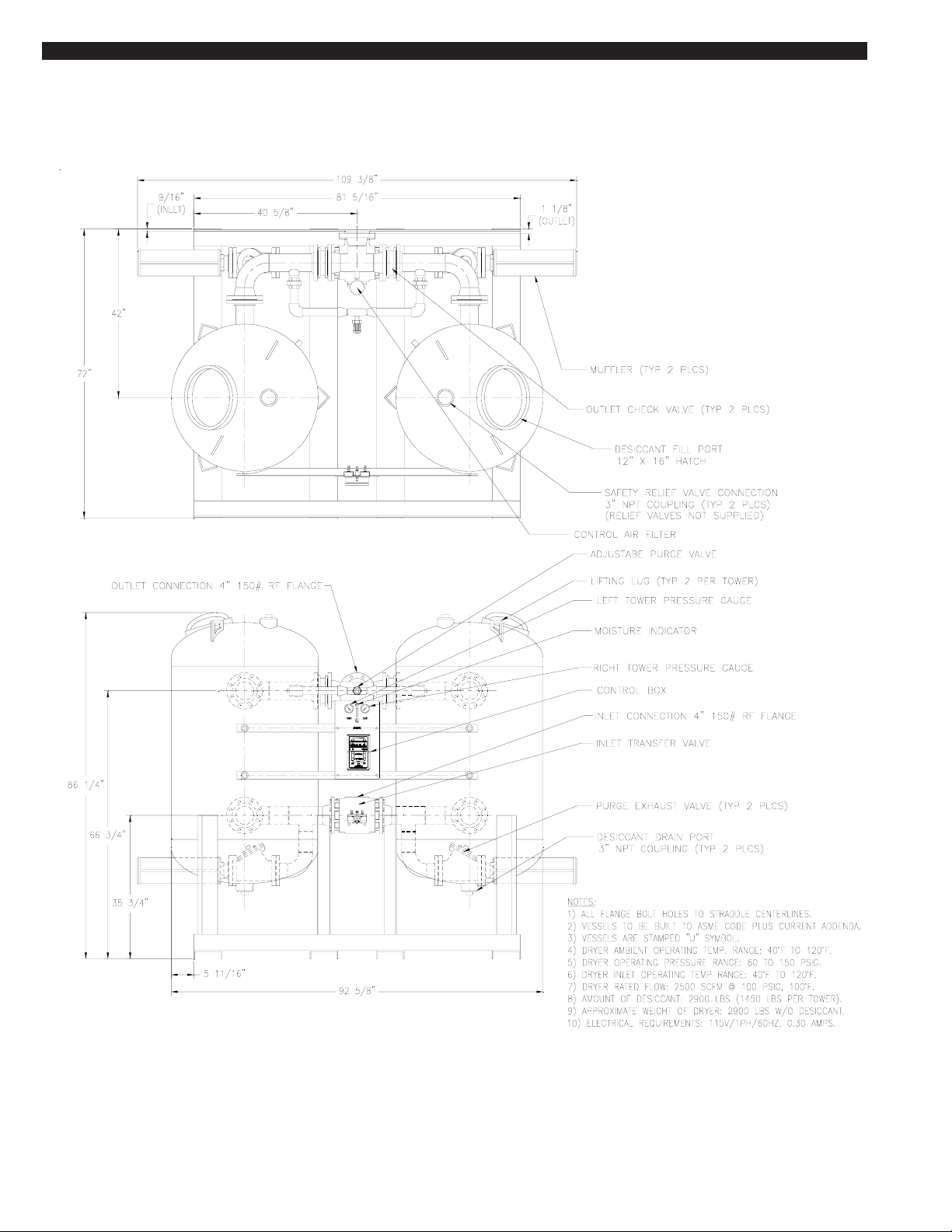
3.2 DIMENSIONS
PAGE 4
Note: Standard control panel (115V) is depicted on this drawing
Page 5

INSTALLING THE DRYER SECTION 4
4.1 LOCATION
WARNING
DO NOT INSTALL THIS DRYER IN AN ENVIRONMENT OF
CORROSIVE CHEMICALS, EXPLOSIVE GASSES, POISONOUS
GASSES, OR SATURATED STEAM HEAT.
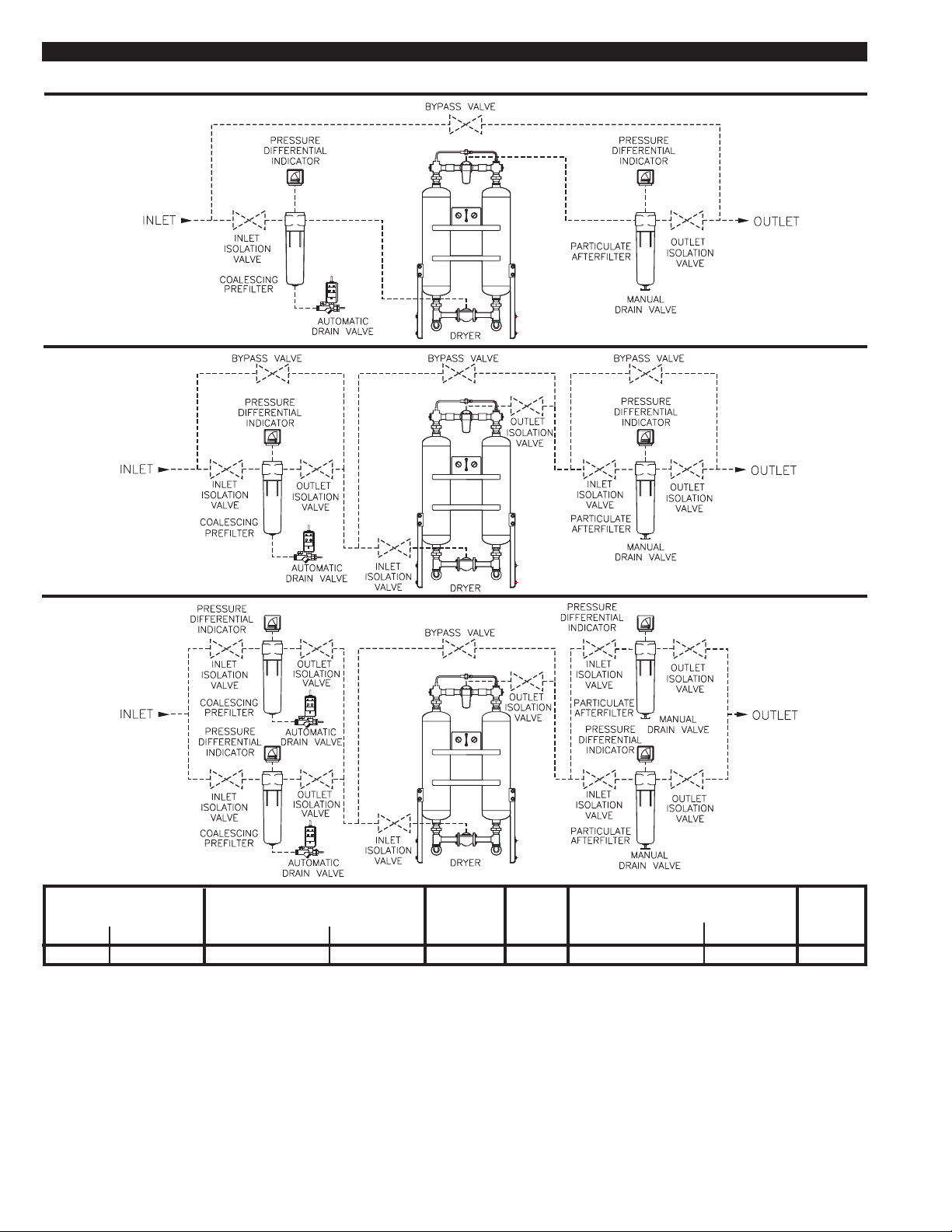
Basic bypass piping should include an inlet isolation valve, a bypass
valve, and an outlet isolation valve. The isolation and bypass valves
must be bubble-tight.
4.2-2 FILTERS
Locate dryer in a protected, well vented area where ambient
temperatures are between 40oF and 120oF. Allow sufficient clearance
over and around the dryer for access to desiccant fill and drain ports
and controls. Refer to SECTION 3.2 for dryer dimensions.
If this dryer must be installed where ambient temperatures are below
40oF, insulation and heat tracing must be properly installed on the inlet
piping, purge exhaust line and the desiccant towers to prevent freezing
of the equipment.
Position the dryer in the upright position on a solid, level, vibration free
surface capable of supporting the dryer’s weight. Refer to SECTION
3.1 for dryer specifications.
The dryer should not be located in extremely dirty areas where
airborne contaminants can accumulate on the dryer. If this cannot be
prevented, the dryer should be cleaned periodically.
4.2 PIPING AND ANCILLARY EQUIPMENT
CAUTION
Make sure that the inlet air piping is connected at the bottom and the
outlet air piping is connected at the top of the dryer.
Make sure that the inlet and outlet piping to and from the dryer is
properly supported. Excessive stress may cause damage and/or
dryer malfunction.
Remove protective caps or covers from all valves before installing this
dryer.
If this dryer is to be installed into an existing piping system, clean the
existing inlet piping to remove all accumulated dirt, pipe scale, etc.,
before connecting the dryer. Make sure that the inlet and outlet
shutoff valves are tightly closed before connecting to the existing
piping system.
If excessive vibrations are present in the piping, install a flexible hose
between the compressor and the dryer inlet.
When installing the piping and any additional components, make sure
that adequate pipe supports are used. Excessive stress on the dryer
and components may cause damage or premature failure. Use either
overhead or stiff-leg type supports.
Make sure that the piping is correctly connected to the dryer. The inlet
is the bottom connection and the outlet is the top connection.
Reference SECTION 3.2 for dryer dimensions and connection
locations.
CAUTION
A PROPERLY RATED COALESCING PREFILTER MUST BE
INSTALLED BEFORE THE DRYER TO REMOVE LUBRICATING
OILS, DUST AND PIPE SCALE CONTAMINATION. FAILURE TO
USE A PREFILTER WILL RESULT IN DAMAGE TO THE DRYER
AND VOIDS THE WARRANTY.
Make sure that the elements are installed in all filter housings
prior to start up.
THE DRYER AND PREFILTER ARE NOT DESIGNED TO HANDLE
LIQUID WATER. IF LIQUID WATER IS PRESENT IN THE AIR
SYSTEM, A SEPARATOR WITH AN AUTOMATIC DRAIN MUST BE
INSTALLED UPSTREAM TO THE PREFILTER AND DRYER TO
PREVENT FLOODING.
A coalescing prefilter must be installed before the dryer to remove
lubricating oils, dust and pipe scale contamination. It is recommended
that a high efficiency coalescing filter with an automatic drain or
electric drain valve be installed. The filter should be equipped with a
pressure differential indicator to monitor the condition of the element.
A particulate afterfilter should be installed downstream of the dryer to
remove any desiccant dust. The filter should be equipped with a
pressure differential indicator to monitor the condition of the element.
Make sure that the filters are properly installed according to the
instructions provided with them.
4.3 INSTALLING THE PRESSURE RELIEF VALVES
CAUTION
THESE ASME CODE VESSELS MUST BE PROTECTED BY
PRESSURE RELIEF VALVES. Refer to OSHA 1910.169 Par. b,
Sub. Par (3) and ASME Boiler and Pressure Vessel Code, Section
VIII, Division 1, UG-125 through UG-136. Also check government
regulations, i.e., state and local codes.
Connections are provided on the top of the vessels for the installation
of pressure relief valves. Reference SECTION 3.2 for location and
connection size.
Install the pressure relief valves into the provided connections. If
pressure relief valves were not purchased with the dryer, they are
available from your local VAN AIR representative under part number
14-0990 quantity 2.
Once the location has been determined, place the dryer into position.
Lift the dryer by the lifting lugs only. Reference SECTION 1 for
handling instructions.
When the dryer is in place, it can be fastened to the mounting surface.
Reference SECTION 3.2 for dryer dimensions.
4.2-1 BYPASS PIPING (optional)
The installation of bypass piping is not required, but will allow the
dryer and filters to be taken off stream without interrupting the air
system.
In Figure 4A, several recommended bypass piping layouts and
additional components are shown.
PAGE 5
Page 6
INSTALLING THE DRYER SECTION 4
FIGURE 4A RECOMMENDED PIPING CONFIGURATIONS AND COMPONENTS
3 VALVE BYPASS
9 VALVE BYPASS
11 VALVE BYPASS
MODEL
HL-2500
IN/OUT
4" RF FLG
PREFILTERDRYER
MODEL
F101-3500-C
IN/OUT
6" RF FLG
DRAIN
VALVE
MODEL
EDV-2006
DEL-P
IND.
MODEL
PD-2
AFTERFILTER
MODEL
F101-2000-RB
IN/OUT
4" RF FLG
DEL-P
IND.
MODEL
PD-2
PAGE 6
Page 7
INSTALLING THE DRYER SECTION 4
4.4 REMOTE PURGE EXHAUST PIPING
To reduce noise during purging and tower depressurization, this dryer
was supplied with mufflers for installation on the purge exhaust valves.
If the sound or humidity discharged from the dryer is unacceptable, the
purge can be piped to a remote location.
Make sure that the piping is as short as possible and does not
create back pressure on the dryer. To prevent liquid accumulation in the piping and purge valves, the piping must be at the
same level or lower than the purge valves.
The purge line must be vented to atmospheric pressure. If the
ambient temperature at the venting end of the piping is subject
to temperatures below 40
The purge valves have threaded pipe connections. Reference
Section 3.2 for location. Use adequate pipe supports to prevent
stress on valves.
The distance will determine the size of piping that is recommended.
For distances of 10 feet or less, use piping of the same size as the
purge valves. For distances up to 20 feet, use piping one size larger
than the purge valves.
IMPORTANT
o
F, freeze protection must be installed.
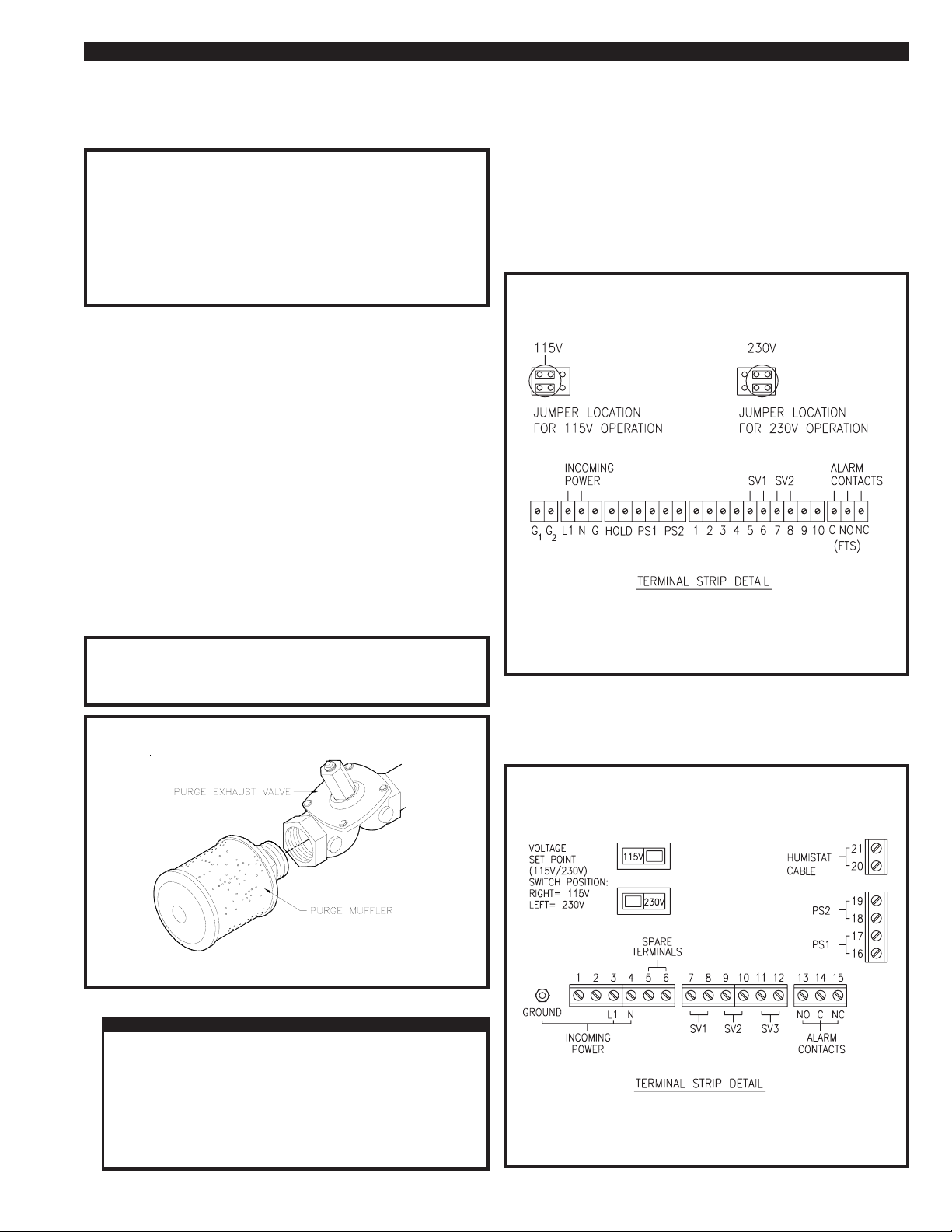
4.6-1 STANDARD CONTROL BOX (115V & 230V)
The power supply to the dryer is to be connected to the dryer control
box. A 7/8" dia hole was provided in the bottom of the box for the
connection of conduit or a cord grip connector.
Check the electrical rating of the dryer as listed on the dryer data tag.
Make sure that the power source is correct for the dryer rating.
Remove the box cover to access the power and alarm terminals.
Wire the power supply as shown in Figure 4C (Standard Control
Box). Connect the wiring to the dryer box. Comply with all codes
applicable for this installation.
FIGURE 4C ELECTRICAL CONNECTIONS
(STANDARD CONTROL BOX)
4.5 INSTALLING THE PURGE MUFFLERS
To reduce the sound level during purge and tower depressurization,
this dryer was supplied with mufflers for installation on the purge
exhaust valves.
Mufflers were shipped separately. They should NOT be installed until
the dryer has been operated for several hours. From desiccant
installation, some dust may be present in the desiccant towers.
Operating the dryer with the mufflers installed immediately after the
towers have been filled with the desiccant or during initial start up may
cause the mufflers to clog.
The dryer must be operated for several hours without the
mufflers after the towers have been filled with desiccant. This
will prevent the mufflers from becoming clogged.
IMPORTANT
FIGURE 4B PURGE MUFFLER INSTALLATION
NOTE
Dryer Model HL-2500 Has flanged
muffler connections.
Control Power: 115V /1PH/50-60Hz; 230V/1PH/50-60Hz
Max amp draw: 0.3 AMPS; 0.15 AMPS
General Alarm Contacts: 115V-230V/1PH/60Hz, 0.25 amps
4.6-2 CYCLE SAVER / FAILURE TO SWITCH (115V & 230V)
Same instructions as Standard Control Box except wire the power
supply as shown in Figure 4D (Cycle Saver / Failure To Switch).
FIGURE 4D ELECTRICAL CONNECTIONS
(CYCLE SAVER / FAILURE TO SWITCH)
4.6 ELECTRICAL CONNECTIONS
WARNING
SERIOUS PERSONAL INJURY AND DAMAGE TO THE DRYER
WILL OCCUR IF THE DRYER IS CONNECTED TO A POWER
SOURCE OTHER THAN THE VOLTAGE LISTED ON THE DATA
TAG.
WHEN INSTALLING THE ELECTRICAL CONNECTIONS FOR
THIS DRYER, COMPLY WITH NATIONAL ELECTRICAL CODE
AND ALL APPLICABLE FEDERAL, STATE AND LOCAL
CODES
Control Power: 115V /1PH/50-60Hz; 230V/1PH/50-60Hz
Max amp draw: 1 AMPS; 0.5 AMPS
General Alarm Contacts: 115V-230V/1Ph/60Hz, 3 amps
PAGE 7
Page 8
INSTALLING THE DRYER SECTION 4
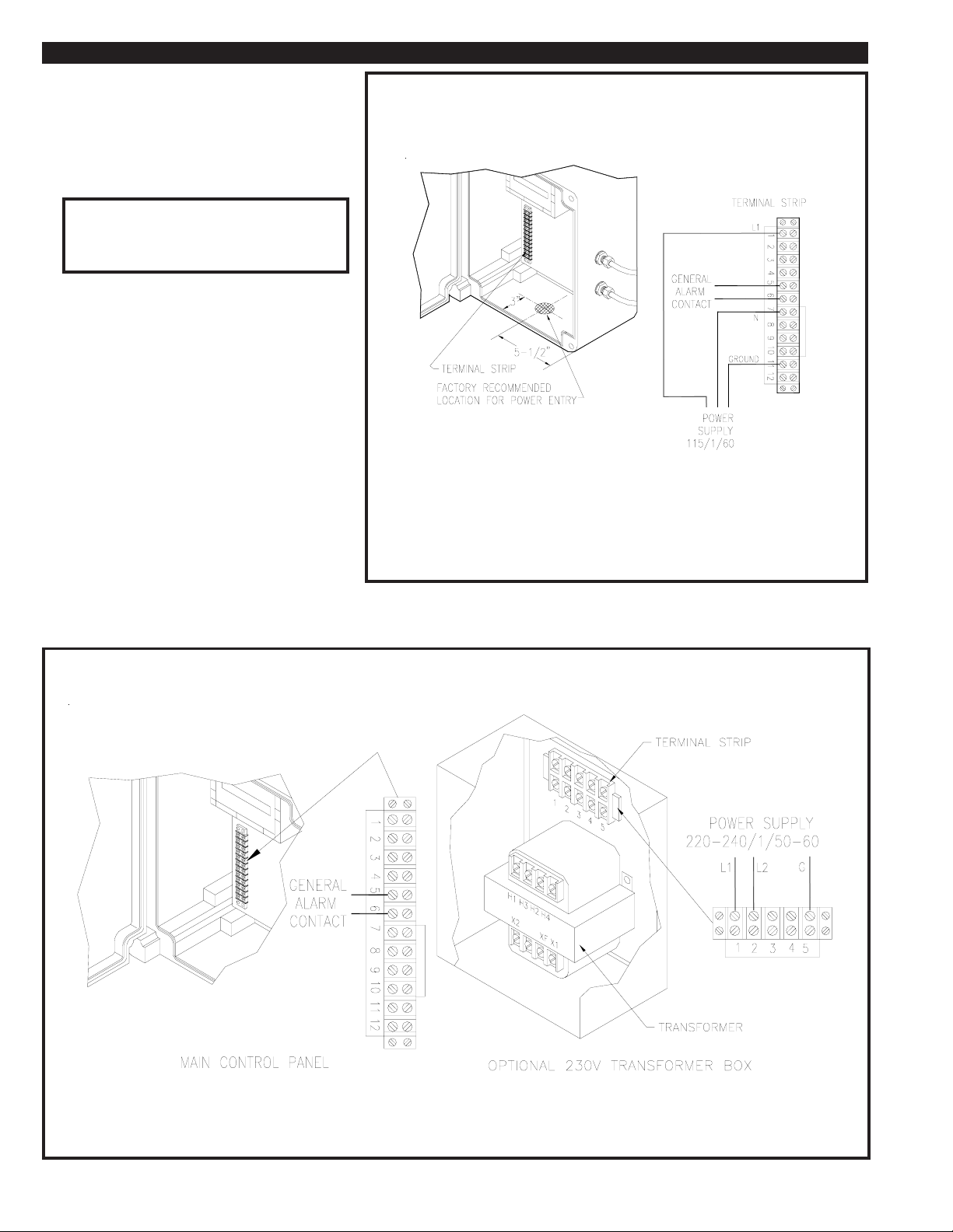
4.6-3 EMCON II (115 VOLT)
The electrical controls for the Emcon II dryers are
housed in a NEMA 4 rated fiberglass enclosure.
Reference Figure 4E to locate the power input
terminals. Access into the enclosure for wiring and
conduit can be made by carefully drilling a hole in
the bottom of the enclosure.
FIGURE 4E ELECTRICAL CONNECTIONS EMCON II (115 VOLT)
Do NOT wire the power supply directly to the
IMPORTANT
PLC. Wire the power supply to the input
terminals as shown in Figure 4E.
Connect the proper conduit and wiring as required
for this installation by all applicable codes.
Make the necessary connections to the power input
terminals.
4.6-4 EMCON II (230 VOLT)
The main electrical controls for the Emcon II dryers are
housed in a NEMA 4 rated fiberglass enclosure.
Dryers rated for 230V/1PH/60Hz are equipped with a
power transformer located in a separate enclosure on
the dryer. All main power supply (230V) connections
will be made in the transformer enclosure.
Reference Figure 4F for connection details. Connect
to the enclosure using the proper conduit and wiring as
required for this installation by all applicable codes.
Control Power: 115V/1PH/60Hz
Max amp draw: 2 AMPS
General Alarm Contacts: 115V-230V/1PH/60Hz, 2 amps
FIGURE 4F ELECTRICAL CONNECTIONS EMCON II (230 VOLT)
General Alarm Contacts: 115V-230V/1PH/60Hz, 2 amps
PAGE 8
Page 9
START UP SECTION 5
5.1 START UP
WARNING
BEFORE STARTING THIS DRYER, FOLLOW THE INSTALLATION
INSTRUCTIONS AND PROCEDURES COMPLETELY. SERIOUS
PERSONAL INJURY CAN RESULT IF INSTRUCTIONS ARE NOT
CAREFULLY AND COMPLETELY FOLLOWED.
DO NOT REMOVE, REPAIR, OR REPLACE ANY ITEM ON THIS
DRYER WHILE IT IS PRESSURIZED.
For the Standard Control Box, make sure the Stop button is pressed.
For the Cycle Saver and Emcon II Control Boxes, make sure that the
Power switch is in the OFF position.
If the dryer is being started up for the first time or after the
desiccant has been changed, the purge mufflers must be removed.
The dryer should be operated until no desiccant dust is visible at
the purge valves. Then the mufflers can be reinstalled. See
Section 2.2 for safety precautions concerning the desiccant dust.
WARNING
WHEN OPERATING THIS DRYER WITHOUT THE MUFFLERS
INSTALLED, USE HEARING PROTECTION.
If bypass piping was installed on this dryer as outlined in SECTION 4.2,
close the inlet and outlet isolation valves. Open the bypass valve.
Pressurize the air system. Once the air system is pressurized, slowly
open the inlet isolation valve. DO NOT open the outlet isolation valve.
To start the dryer with a Standard Control Box, press the Run button
which will light the Run LED. For Cycle Saver and Emcon II Control
Boxes, place the Power switch in the ON position. One tower will
already be pressurized. The other tower will depressurize. The purge
valve on the tower that is not pressurized will be open, air should be
exhausting from the muffler.
Dryers equipped with CYCLE SAVER or EMCON II controls will begin a
20 minute start up cycle. While in the start up cycle the dryer will
operate for 5 minutes on each tower to allow the humistat(s) to reach
equilibrium. Any time the dryer is restarted after a loss of power or
pressure in both towers, it will restart in the start up cycle.
The dryer is equipped with a purge metering valve. The setting should
be checked before placing the dryer on stream.
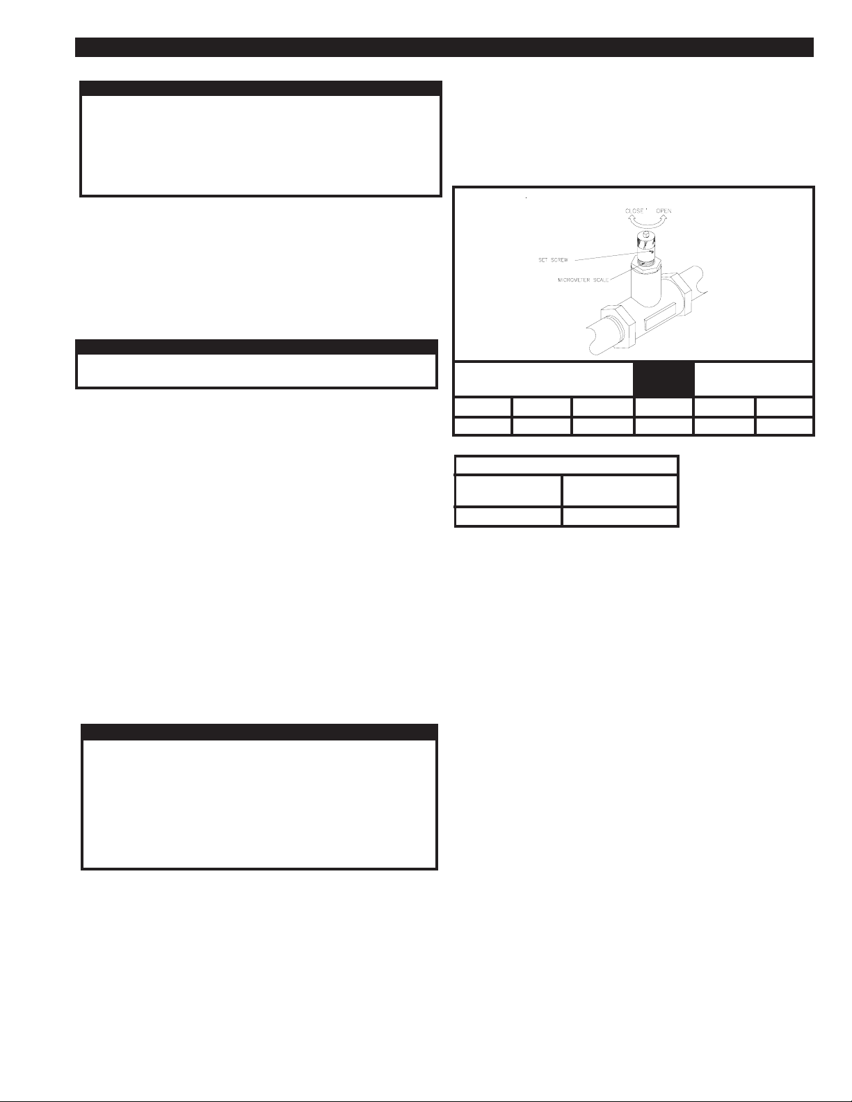
5.2 ADJUSTING THE PURGE FLOW
IMPORTANT
NEVER OPERATE THE DRYER WITH THE PURGE METERING
VALVE CLOSED. IF THE VALVE IS CLOSED, THE TOWERS WILL
NOT REPRESSURIZE AND SWITCHING FAILURE WILL OCCUR.
conditions, the purge metering valve must be adjusted to maintain the
required purge flow rate listed in Figure 5B.
Determine the dryer minimum operating pressure. Using the chart in
Figure 5A, find the valve setting for that pressure. The valve is equipped
with a set screw which must be loosened before the valve is adjusted.
Adjust the needle valve to the desired setting. Tighten the set screw to
prevent tampering.
FIGURE 5A PURGE METERING VALVE SETTINGS
FACTORY
SETTING
PURGE
FLOW
100 PSIG
4.0 turns
120 PSIG
3.5 turns
150 PSIG
3.2 turns
MODEL
HL-2500
FIGURE 5B REQUIRED PURGE FLOW
4.5 turns
DRYER
MODEL
HL-2500
60 PSIG
80 PSIG
4.2 turns
450 SCFM
5.3 CONDITIONING THE DESICCANT BED
To condition the desiccant bed, the dryer is operated without any outlet
flow, while the towers regenerate with purge air.
To start the dryer with a Standard Control Box, press the Run button,
which will light the Run LED. For Cycle Saver and Emcon II Control Boxes,
place the Power switch to the ON position.
Dryers equipped with the Standard Contol Box should be set on the 10
minute time cycle. Dryers equipped with Emcon II and Cycle Saver
should be set in the Fixed Mode. Observe the dryer for several cycles.
Make sure that it is operating properly.
At initial start up or after extended shutdowns (over one month), the dryer
may take 24 to 48 hours of continuous operation for the bed to be
conditioned. Moisture that has accumulated on the desiccant bed should
be removed before the dryer is placed on stream.
DO NOT ADJUST THE PURGE METERING VALVE ABOVE OR
BELOW THE RECOMMENDED SETTING FOR THE OPERATING
CONDITIONS OF THIS INSTALLATION. IMPROPER SETTING MAY
CAUSE POOR DRYER PERFORMANCE AND/OR EXCESSIVE USE
OF PROCESS AIR.
The purge flow can be adjusted for the operating conditions. Standard
dryers are equipped with a micrometer type needle valve. The valve can
be adjusted to the desired setting.
This dryer was shipped with the purge flow set for the rated inlet flow at
100 PSIG. Reference Section 3.1 for rated flow. This setting should be
correct for most installations. Before placing the dryer on stream, check
the purge metering valve setting.
Figure 5B shows the purge flow required for each model. This flow is
required to properly regenerate the desiccant beds.
If the dryer is being operated at a pressure other than inlet rated
Once the moisture indicator on the dryer turns blue, the desiccant bed
is ready. Place the dryer on stream by opening the outlet isolation valve.
Make sure that the by-pass valve is closed.
PAGE 9
Page 10
PRINCIPLE OF OPERATION SECTION 6
6.1 PRINCIPLE OF OPERATION
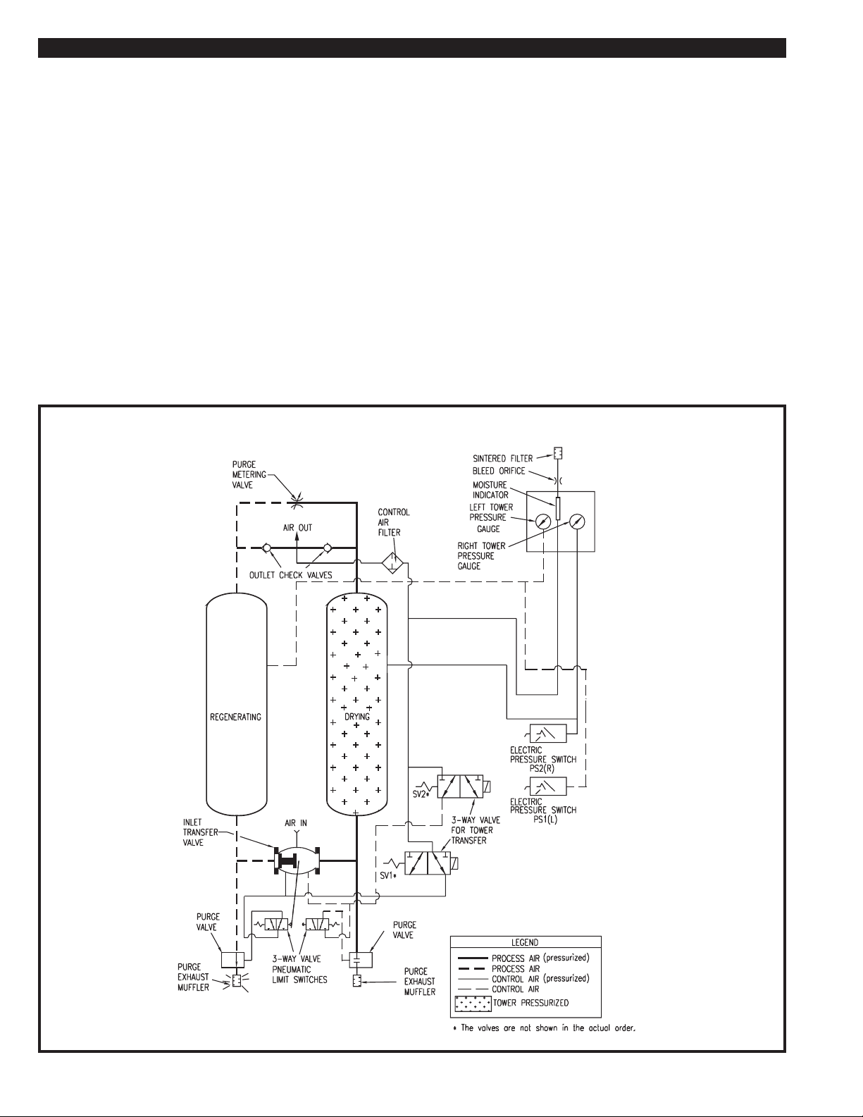
HL Series Heatless Regenerative Air Dryers utilize the pressure swing
principle of operation. The desiccant bed in one tower dries the air stream
while the desiccant bed in the other tower is regenerated.
To achieve maximum performance from this dryer, it should be
operated continuously. Operating this dryer for single shift periods may
result in varied outlet dew point performance.
A purge of dry air is used for tower regeneration. It is taken from the outlet
of the dryer.
The dryer is equipped with a purge metering valve to allow the correct
amount of dry air to flow into the regenerating tower. The heat created
during adsorption of moisture in the drying tower is retained in the
desiccant bed and increases the moisture removal capacity of the purge
air.
The timing cycle of the dryer is controlled by two 3-way pilot valves.
A patented shuttle valve system is used to repressurize, changeover, and
depressurize the towers. The inlet transfer valve is controlled by the pilot
valves. The movement of the shuttle in the inlet transfer valve mechanically
actuates the external pneumatic limit switches, which open the purge
valves and depressurize the tower. The shuttle cannot shift until the tower
pressures are nearly equal. The dryer cannot depressurize until the
shuttle has fully seated and the one of the limit switches is engaged.
The dryer operation consists of four stages; REPRESSURIZATION,
CHANGEOVER/DEPRESSURIZATION, DRYING and
REGENERATION.
6.1-1 REPRESSURIZATION STAGE
Repessurization occurs in the regenerating tower. Repessurization
must occur before tower changover. This reduces shock to the
desiccant and the possibility of downstream pressure spikes.
The purge valve is closed and the purge air, which was vented to
atomosphere earlier in the cycle, is now used to repressurize the
regenerated tower.
The pilot valves SV1 & SV2 de-energize causing the purge valve on the
regenerating tower to close. The purge air, which was vented to
atmosphere earlier in the cycle, is now used to repressurize the
regenerated tower.
FIGURE 6A PNEUMA TIC SCHEMATIC for DRYERS WITH STANDARD CONTROL
PAGE 10
Page 11

PRINCIPLE OF OPERATION SECTION 6
6.1-2 CHANGEOVER/DEPRESSURIZATION STAGE
Tower changeover occurs after the previous regenerating tower is
pressurized. The controller signals the inlet transfer valve to switch.
The tower that was on line and drying the process air will begin to
depressurize.
Pressure in the regenerating tower will approach full line pressure. The
pilot valves SV1 or SV2 will energize. Pilot air will be supplied to one
side of the inlet transfer valve. The inlet transfer valve shuttle will move
to the side that has pilot pressure.
When the inlet transfer valve changes position, the position indicator
will move and actuate the other pneumatic limit switch. This will open
the purge valve on the tower that was drying the process air, causing
the tower to depressurize.
CYCLE SAVER and EMCON II models:
If the dryer is being operated in the AUTO MODE, tower changeover
is delayed until the dew point controller(s) signal the circuit board or
PLC. The dryer will automatically change towers after 4 hours of
ENERGY SAVINGS.
6.1-3 DRYING AND REGENERATION STAGE
During the drying stage, one tower is pressurized with process air.
This tower is in the drying stage. The process air passes through the
desiccant bed, which adsorbs moisture from the air. The
regeneration stage of one tower occurs at the same time as the drying
stage in the opposite tower. During the regeneration stage, a
percentage of dry air is directed through the desiccant bed of the
offstream tower. The purge air is vented through the purge valve to
the atmosphere.
The pilot valves SV1 or SV2 are either energized or de-energized
depending on which tower is on stream (drying). If SV2 is energized, the
LEFT tower is drying and if SV1 is energized, the RIGHT tower is drying.
6.2 MOISTURE INDICATOR
The moisture indicator is in the center of the panel. The moisture
indicator is a clear plastic tube filled with moisture sensing crystals. A
sample of outlet air is directed through the indicator.
The crystals will change colors from PINK (indicating wet air) to
BLUE (indicating dry air) as the dew point of the air changes from
O
F to -40OF.
+20
FIGURE 6B PNEUMATIC SCHEMA TIC for DRYERS WITH CYCLE SAVER OR EMCON II
Pneumatic schematic shown above for units equipped with CYCLE
SAVER.
Pneumatic schematic shown above for units equipped with PLC controls
featuring EMCON II.
PAGE 11
Page 12
USING THE STANDARD CONTROL SECTION 7
7.1 STANDARD CONTROL
The STANDARD CONTROL is a compact NEMA 4X control box. It has the
following features:
• Dryer Status LEDs
- POWER ON - L/R TOWER DRYING
- RUN - L/R TOWER REGENERATING
- HOLD - DRYER PURGING
- SWITCHING FAILURE
The Dryer Status LEDs are located on the front panel of the control box.
Figure 7A shows the location of each. Note: There is a Red LED located
on the inside of the control box. This LED flashes on and off indicating
the timer is active.
Start the dryer per SECTION 5.1. When the Left tower is pressurized and on
line drying the process air, the corresponding LEFT TOWER DRYING LED is
illuminated. When the right tower is pressurized and on line drying the
process air, the corresponding RIGHT TOWER DRYING LED is illuminated.
The DRYER PURGING LED is illuminated when the corresponding purge
exhaust valve is open. During repressurization this LED will not be illuminated. Repressurization occurs for approximately 20 seconds just before
tower changeover. The operation timing sequence of the dryer is shown in
Figure 7C TIMING CHART FOR STANDARD CONTROL.
FIGURE 7A CONTROL BOX FRONT PANEL
POWER ON
HOLD
LEFT
STOP
RUN
SWITCHING FAILURE
TOWER DRYING
TOWER REGENERATING
RUN
RIGHT
SWITCHING FAILURE:
When there is a switching failure, the LED will be lit. This will energize the
contacts shown in Figure 4C. The contacts can be wired for remote
annunciation. To reset the Switching Failure Alarm press the Run button
on the control box front panel.
HOLD FEATURE:
For Low load or Static pressure conditions, the hold contacts shown on
Figure 4C can be wired to an auxiliary set of normally closed contacts on
the compressor starter. This will stop the cycling of the dryer and
repressurize both towers of the dryer, until there is demand on the
compressor. The Hold LED will light, if the dryer is wired as described and
the compressor is not running.
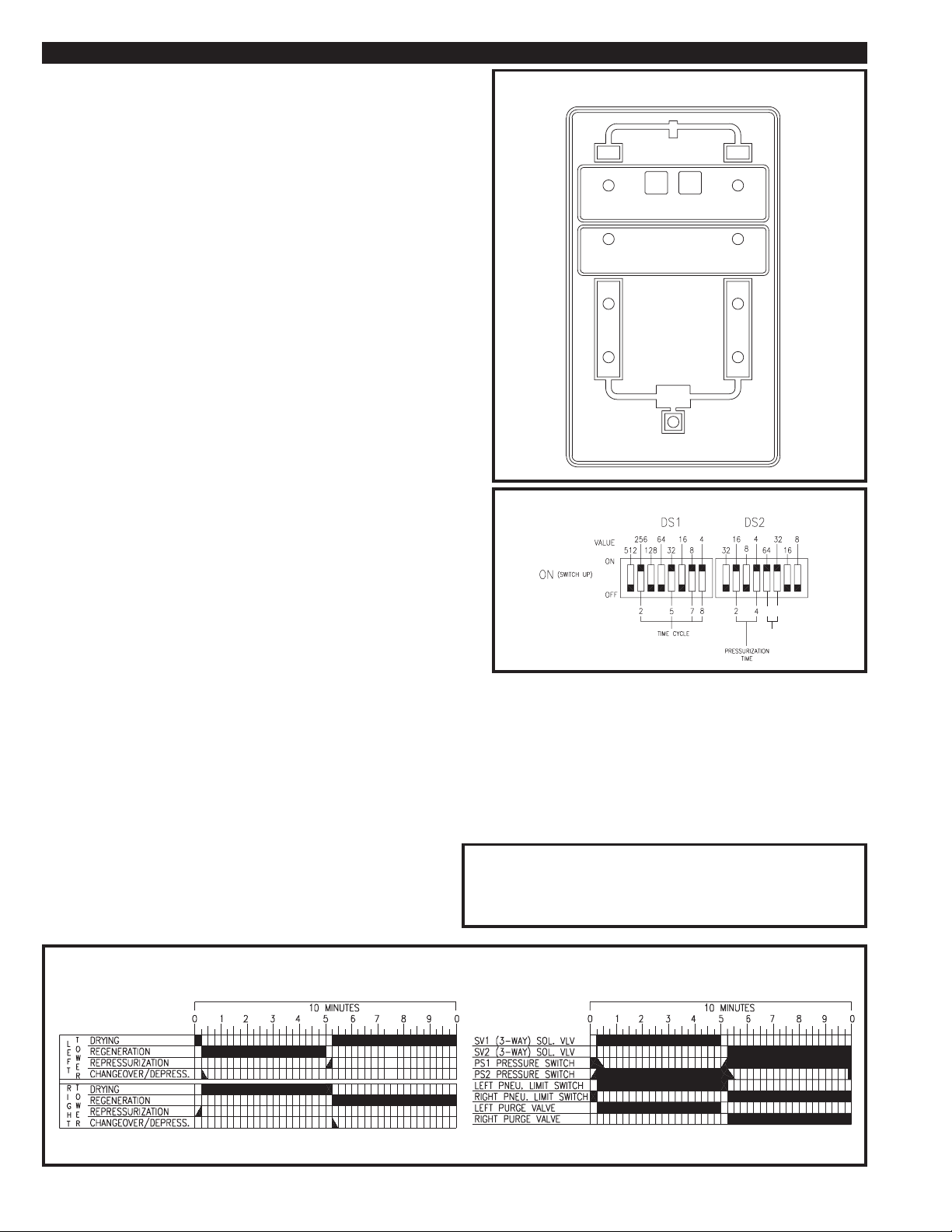
7.2 SETTING THE CYCLE TIME
Reference Figure 7B:
The setting for the time cycle is a 5 min/half cycle. For the half cycle
time setting, the switches indicated for DS1 (2, 5, 7, & 8) as shown in
the CYCLE TIME DETAIL have been factory set by pushing the
switches up. The values for these switches are (256, 32, 8, & 4) sec.,
so when added together equal 300 sec or 5 min. WE DO NOT
RECOMMEND a time cycle setting below 2 min/half cycle. For this
half cycle time setting, the switches that need to be pushed up are DS1
(4, 5, 6, & 7) their values are (64, 32, 16, & 8) sec. so when added
together equal 120 sec or 2 min.
The setting for the pressurization time is 20 sec. For the pressurization time setting, the switches indicated for DS2 (2 & 4) as shown in
the CYCLE TIME DETAIL have been factory set by pushing the
switches up. The values for these switches are (16 & 4) sec., so when
added together equal 20sec. WE DO NOT RECOMMEND CHANG-
ING THIS SETTING.
DRYER PURGING
FIGURE 7B CYCLE TIME DETAIL
5
6
FTS
ALARM
The setting for the alarm time is 96 sec. For the alarm time setting,
the switches indicated for DS2 (5 & 6) as shown in the CYCLE TIME
DETAIL have been factory set by pushing the switches up. The values
for these switches are (64 & 32) sec., so when added together equal
96 sec. WE DO NOT RECOMMEND CHANGING THIS SETTING.
NOTE: THE ALARM TIME SETTING NEEDS TO BE LESS THAN
THE HALF CYCLE TIME SETTING OR THIS WILL NEGATE
THE ALARM FUNCTION.
Operating this dryer on the 4 minute cycle will more than
double the wear on the dryer components. To reduce wear on
the dryer, operate the dryer on the 10 minute cycle if the -40OF
dew point is acceptable.
IMPORTANT
FIGURE 7C TIMING CHART FOR STANDARD CONTR OL
PAGE 12
Page 13
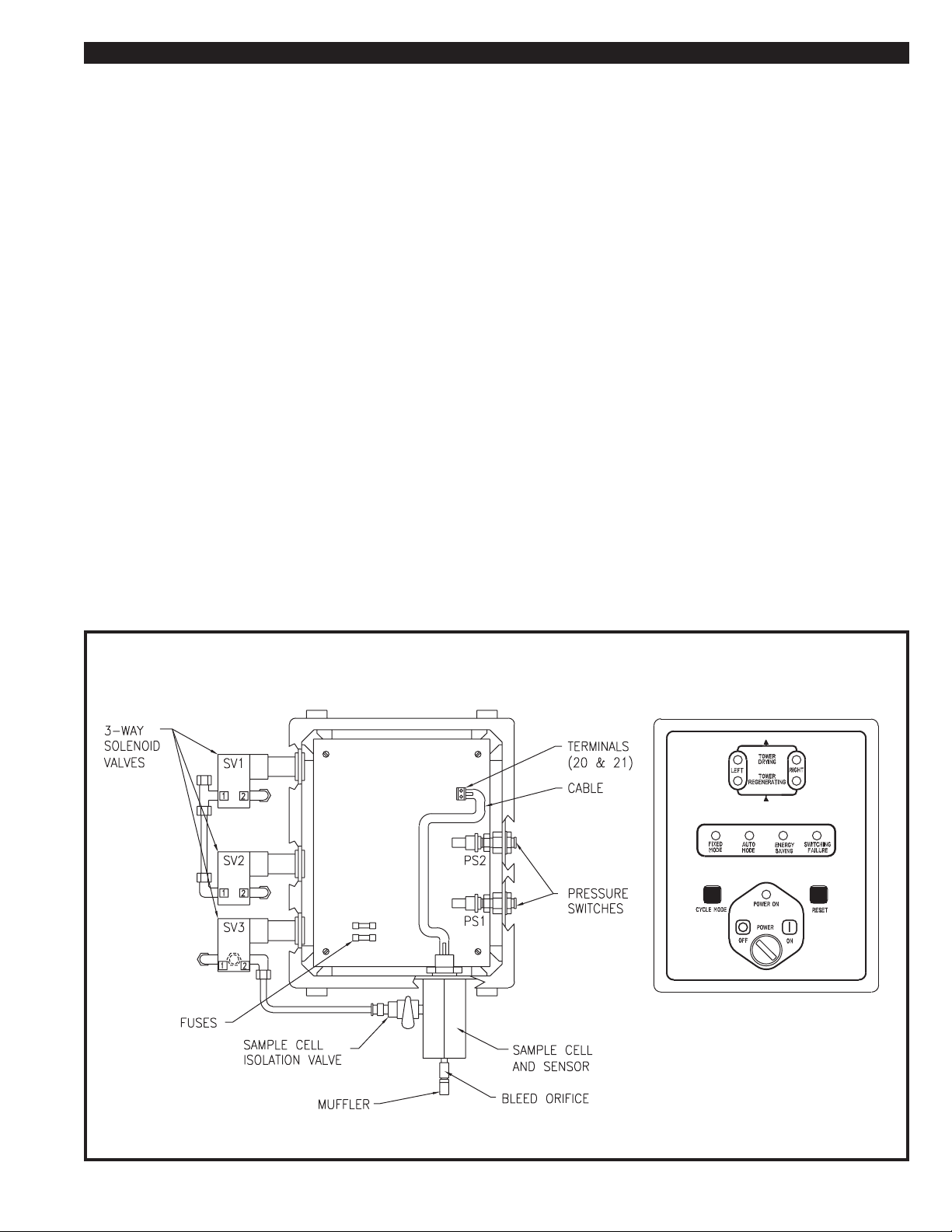
USING THE CYCLE SAVER CONTROL SECTION 8
8.1 CYCLE SAVER CONTROL
The CYCLE SAVER control uses a printed circuit board. It is housed
in a NEMA 4X fiberglass enclosure. It has the following features:
- POWER SWITCH
- POWER ON LED
- CYCLE MODE PUSHBUTTON
- FIXED MODE LED
- AUTO MODE LED
The Dryer Status LEDs are located on the front panel of the control
box. Figure 8A shows the location of each. Note: There are six
other LEDs located on the inside of the control box. Reference
SECTION 8.5.
Start the dryer per SECTION 5.1. When the left tower is pressurized
and on line drying the process air, the corresponding LEFT TOWER
DRYING LED will be lit. When the right tower is pressurized and on
line drying process air, the corresponding RIGHT TOWER LED is
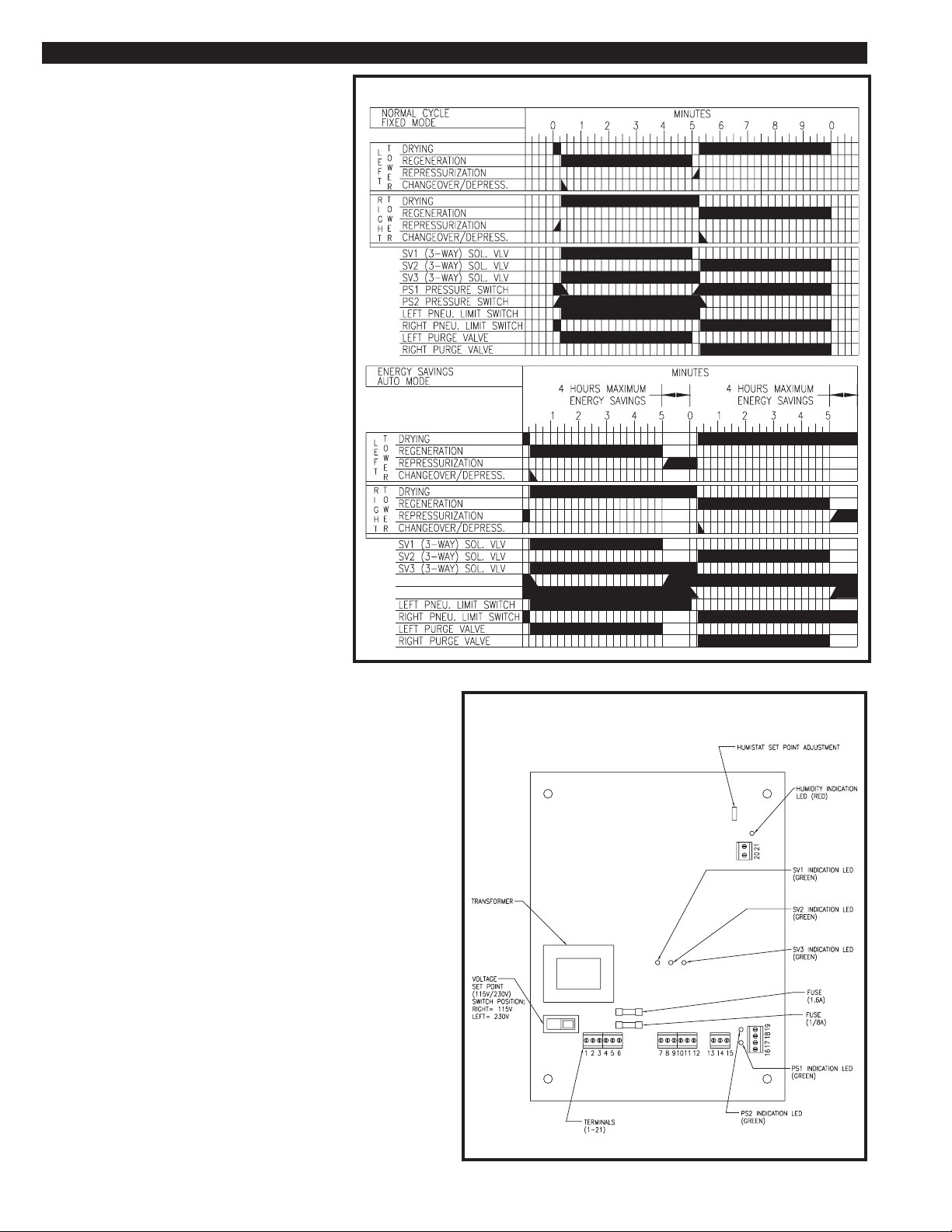
illuminated. The operation timing sequence of the dryer is shown in
Figure 8B TIMING CHART FOR CYCLE SAVER.
- ENERGY SAVINGS LED
- SWITCHING FAILURE LED
- RESET PUSHBUTTON
- L/R TOWER DRYING LEDS
- L/R TOWER REGENERATING LEDS
8.2 SETTING THE CYCLE MODE
Pressing the Cycle Mode Pushbutton will alternate between the FIXED
and AUTO modes. This will light either the Fixed or Auto Mode LED.
8.2-1 OPERATING THE DRYER IN THE FIXED MODE
When operating the dryer in the FIXED MODE, press the Cycle
Mode Pushbutton until the Fixed Mode LED is lit. The dryer will not
utilize the ENERGY SAVINGS feature.
The fixed cycle is a normal 10 minute cycle. The dryer changes
towers every five minutes. The dryer goes through a normal tower
changeover sequence (repressurization, tower changeover,
depressurization).
The SWITCHING FAILURE ALARM is operational in both the
FIXED and AUTO modes.
8.2-2 OPERATING THE DRYER IN AUTO MODE
When operating the dryer in the AUTO MODE, press the Cycle
Mode Pushbutton until the Cycle Mode LED is lit.
The dryer will operate in the start up cycle for the first 20 minutes of
operation at every start up. After the start up cycle has been
completed, the dryer will operate in the mode that the Cycle Mode is
set (FIXED or AUTO).
In the Auto Mode, the length of time that a tower is in the drying
stage is controlled by the humistat set point adjustment on the
printed circuit board.
8.2-2A ENERGY SAVINGS
At the end of a normal regeneration stage, if the tower humistat
indicates a good dew point, ENERGY SAVINGS has been
activated. If the dew point is not low enough to activate ENERGY
SAVINGS, the dryer will switch towers.
When ENERGY SAVINGS is activated, the ENERGY SAVINGS
LED is illuminated. The purge exhaust valve on the regenerating
tower is closed and that tower comes up to full line pressure. No
purge air will be exhausted at this time.
The tower that was in the drying stage will remain on line and
drying the process air until the dew point rises to the set point of
the humistat.
The maximum time a tower can stay in energy savings is four
hours. This is to prevent channeling of the desiccant under very
low flow conditions.
FIGURE 8A CYCLE SA VER CONTROL BOX
PAGE 13
Page 14
USING THE CYCLE SAVER CONTROL SECTION 8
LEFT TOWER PRESSURE (PS1)
RIGHT TOWER PRESSURE (PS2)
8.3 FAILURE TO SWITCH ALARM
The FAILURE TO SWITCH ALARM is operational in
the FIXED and AUTO modes.
The dryer is continuously being monitored for
switching failure. Two pressure switches monitor the
pressure in the desiccant towers. If pressure is
present in the tower that should be in the regenerating stage, the alarm is activated. The printed circuit
board gives the dryer 90 seconds to depressurize
after tower changeover before the alarm is activated.
If one or both of the pressure switches fail, the
alarm is NOT activated, but the dryer is switched into
a 10 minute fixed cycle.
When the alarm is activated, the FAILURE TO
SWITCH LED is illuminated. The alarm does not
stop the dryer from cycling. The FAILURE TO
SWITCH ALARM is a latching alarm. Once the
problem causing the switching failure is corrected,
the FAILURE TO SWITCH RESET PUSHBUTTON
must be pressed to reset the alarm. If the alarm is
reset and the problem is not corrected, the alarm will
be re-activated after 90 seconds.
The switching failure alarm will activate when:
• The inlet transfer valve does not change
positions and does not direct the process flow
through the proper tower.
• The purge exhaust valve does not open on the
regenerating tower or if tower pressure in the
regenerating tower does not drop below 40 psig.
• The purge exhaust valve does not close on the
regenerating tower to allow repressurization.
FIGURE 8B TIMING CHART FOR CYCLE SAVER
The GENERAL ALARM contact is closed when this
alarm is activated.
8.4 GENERAL ALARM
The general alarm contact was provided for the customer to wire the
dryer’s alarm into a main control room, or to a warning light or horn.
The contact is a normally open dry contact. The contact is closed if
the SWITCHING FAILURE ALARM has been activated. The contact
will only reset if the alarm condition is corrected.
8.5 PRINTED CIRCUIT BOARD (LEDs)
The Humidity Indication LED (RED) is on when the humidity is above
the set point.
The SV1 Indication LED (GREEN) is on when the valve is energized.
The SV2 Indication LED (GREEN) is on when the valve is energized.
The SV3 Indication LED (GREEN) is on when the valve is energized
The PS1 Indication LED (GREEN) is on when the switch is closed.
The PS2 Indication LED (GREEN) is on when the switch is closed.
Note: These LEDs are located on the inside of the control box on
the printed circuit board. Figure 8C illustrates the LEDs locations.
FIGURE 8C CYCLE SAVER PRINTED CIRCUIT BOARD
PAGE 14
Page 15
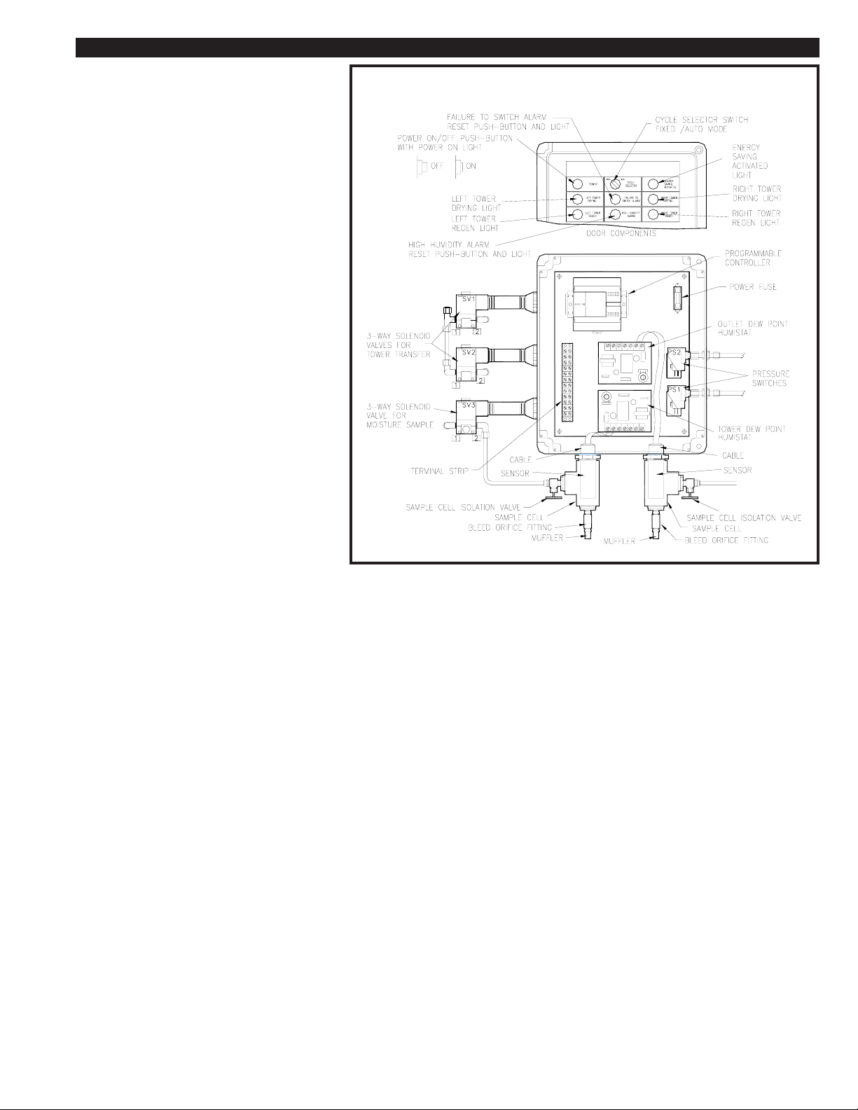
USING THE EMCON II CONTROL SECTION 9
9.1 EMCON II CONTROL
The EMCON II control is programmable logic
controller (PLC) based. It is housed in a NEMA 4X
fiberglass enclosure.
The EMCON II control has the following features:
• Power Push-button/Light
• Cycle Selector Switch Fixed/Auto
• Energy Saving Activated Light
• Tower Status Lights
Left and Right Tower Drying
Left and Right Tower Regenerating
• Failure To Switch Alarm Light/Reset Push-button
• High Humidity Alarm Light/Reset Push-button
The Tower Status Lights are used to indicate which
tower is on line drying the process air and which
tower is regenerating.
The FAILURE TO SWITCH ALARM LIGHT is
illuminated when the Failure To Switch Alarm is
activated. The light is also a push-button which
resets the alarm.
The HIGH HUMIDITY ALARM LIGHT is illuminated
when the High Humidity Alarm is activated. The
light is also a push-button which resets the alarm.
FIGURE 9A EMCON II CONTROL BOX
9.2 SETTING THE CYCLE SELECTOR
SWITCH
The Cycle Selector Switch is used to switch the
dryer cycle. When the switch is set to the FIXED
MODE, the dryer will operate on a 10 minute
cycle. When the switch is set to the AUTO
MODE, the dryer cycle is controlled by the PLC,
the tower dew point controller and the outlet dew
point controller.
When the dryer is operated in the AUTO MODE and the dew point
controllers allow the dryer to operate in an extended cycle, the
ENERGY SAVINGS ACTIVATED LIGHT is activated.
9.2-1 OPERATING THE DRYER IN FIXED MODE
To operate the dryer in the FIXED MODE, set the CYCLE SELECTOR SWITCH to the FIXED position. The dryer will not utilize the
ENERGY SAVINGS feature.
The fixed cycle is a normal 10 minute cycle. The dryer changes
towers every five minutes. The dryer goes through a normal tower
changeover sequence (repressurization, tower changeover,
depressurization).
ENERGY SAVINGS, the dryer will switch towers.
When ENERGY SAVINGS is activated, the ENERGY SAVINGS
ACTIVATED light will be illuminated. The purge exhaust valve on
the regenerating tower is closed and that tower comes up to full
line pressure. No purge air will be exhausted at this time.
The tower that was in the drying stage will remain on line and
drying the process air until the dew point rises to the set point of
either humistat.
The maximum time a tower can stay in energy savings is four
hours. This is to prevent channeling of the desiccant under very
low flow conditions.
The SWITCHING FAILURE ALARM and the HIGH HUMIDITY
ALARM are operational in both the FIXED and AUTO modes.
9.2-2 OPERATING THE DRYER IN AUTO MODE
To operate the dryer in the AUTO MODE, set the CYCLE SELECTOR SWITCH to the AUTO position.
The dryer will operate in the start up cycle for the first 20 minutes of
operation at every start up. After the start up cycle is completed,
the dryer will operate in the mode that the CYCLE SELECTOR
SWITCH is set (FIXED or AUTO).
In the auto mode, the length of time that a tower is in the drying
stage is controlled by the microprocessor and both the tower and
outlet humistats.
9.2-2A ENERGY SAVINGS
At the end of a normal regeneration stage, if both the outlet and
tower humistats indicate good dew points, ENERGY SAVINGS is
activated. If the dew points are not low enough to activate
9.2-2B DEW POINT CALIBRATION CYCLE
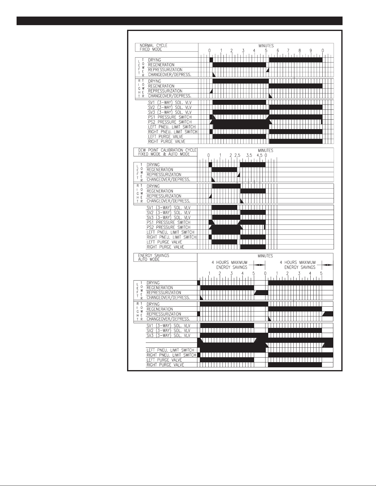
When the dryer is in the calibration, cycle it will switch towers
every 2.5 minutes. By reducing the drying cycle, the inlet
moisture load on the towers will be decreased. This will try to
push the drying mass transfer zone lower in the desiccant bed.
If the dew point of either tower stays high continuously for five
consecutive drying cycles on that tower, the microprocessor will
start short cycling the dryer. The dryer will remain in the
calibration cycle until the tower dew point meter detects a good
dew point in each tower for at least 10 seconds of each drying
stage.
If the outlet dew point rises above the set point of the outlet
humistat any time after the 20 minute start up cycle, the dryer will
be switched into the calibration cycle for a minimum of 20
minutes, even if the outlet dew point returns to a good dew point
(below the humistat set point).
If the outlet dew point remains above the humistat set point
PAGE 15
Page 16
USING THE EMCON II CONTROL SECTION 9
continuously for 15 minutes on either tower,
the HIGH HUMIDITY ALARM is activated.
The HIGH HUMIDITY ALARM is a latching
alarm. Before the alarm can be reset, the
dryer must operate for one complete cycle
with the outlet dew point below the outlet
humistat set point. Then the HIGH
HUMIDITY ALARM LIGHT/PUSH-BUTTON
can be pressed to clear the alarm condition.
9.3 FAILURE TO SWITCH ALARM
The FAILURE TO SWITCH ALARM is
operational in the FIXED and AUTO modes.
Two pressure switches monitor the pressure in
the desiccant towers. If pressure is present in
the tower that should be in the regenerating
stage, the alarm is activated. The microprocessor gives the dryer 90 seconds to depressurize after tower changeover before the alarm
is activated.
If one or both of the pressure switches fail, the
alarm is NOT activated, but the dryer is
switched into a 10 minute fixed cycle.
When the alarm is activated, the FAILURE TO
SWITCH LIGHT/Push-button is illuminated.
The alarm does not stop the dryer from cycling.
The FAILURE TO SWITCH ALARM is a
latching alarm. Once the problem causing the
switching failure is corrected, the FAILURE TO
SWITCH LIGHT/PUSH-BUTTON must be
pressed to reset the alarm. If the alarm is reset
and the problem is not corrected, the alarm will
be re-activated after 90 seconds.
FIGURE 9B TIMING CHART FOR EMCON II
The switching failure alarm will activate when:
• The inlet transfer valve does not change
positions and does not direct the process
flow through the proper tower.
• The purge exhaust valve does not open
on the regenerating tower or if the tower
pressure in the regenerating tower does not
drop below 30 psig.
• The purge exhaust valve does not close
on the regenerating tower to allow
repressurization.
The GENERAL ALARM contact is closed when
this alarm is activated.
LEFT TOWER PRESSURE (PS1)
RIGHT TOWER PRESSURE (PS2)
9.4 HIGH HUMIDITY ALARM
The HIGH HUMIDITY ALARM is operational in the FIXED and
AUTO modes. The alarm is disabled while the dryer is in the 20
minute start up cycle. When it is activated the dryer will continue
to operate.
The HIGH HUMIDITY ALARM is a latching alarm condition. To
turn off the light the reset button must be pushed. The GENERAL ALARM contacts are closed when this alarm is activated.
FIXED MODE
After the 20 minute start up cycle, if the outlet dew point
remains above the humistat set point continuously for 15
minutes on either tower, the HIGH HUMIDITY ALARM is
activated.
PAGE 16
AUTO MODE
If the outlet dew point rises above the set point of the outlet humistat
anytime after the 20 minute start up cycle, the dryer will be forced into
the calibration cycle for a minimum of 20 minutes. If the outlet dew
point remains above the humistat set point continuously for 15
minutes on either tower, the HIGH HUMIDITY ALARM is activated.
9.5 GENERAL ALARM
The general alarm contact was provided for the customer to wire the
dryer’s alarms into a main control room, or to a warning light or horn.
The contact is a normally open dry contact. The contact is closed if
either the HIGH HUMIDITY ALARM or the SWITCHING FAILURE
ALARM is activated. The contact will only reset if the alarm condition
has been corrected. There is an individual reset push-button for each
alarm.
Page 17
SHUTDOWN SECTION 10
10.1 SHUTDOWN PROCEDURES
Close the inlet and outlet isolation valves (if installed). Open the bypass
valve (if installed). Let the dryer depressurize completely.
Turn the dryer off by either pressing the Stop button if the dryer has a
Standard Control Box or place the Power ON/OFF switch to the OFF
MAINTENANCE & TROUBLESHOOTING SECTION 11
11.1 DAILY INSPECTION
The following procedures should be performed daily:
• Check the dryer operating conditions, inlet temperature, ambient
temperature, inlet pressure and inlet flow.
• Monitor the dryer for one complete cycle. Make sure it is
operating properly.
• Check the purge mufflers. Purge air should be exhausting from
one of the valves. If oil is present, the dryer and air system may be
contaminated with lubricants.
• Inspect all upstream equipment, aftercoolers, separators, drains
and filters.
• Check the pressure differential indicator on all prefilters and
afterfilters. If the differential pressure is unacceptable, replace the
elements.
• Check the prefilter(s) for proper draining. If the prefilter is not
equipped with an automatic drain, it must be drained manually.
• Make sure that all bypass valves are tightly closed.
• Visually check the dryer and piping for damage.
•
Visually check the dryer moisture indicator (blue dry or pink wet)
position for the Cycle Saver or Emcon II Control Boxes.
If maintenance is to be preformed on the dryer, make sure the dryer is
completely depressurized. Tower pressure gauges must read 0
PSIG before removing any item on the dryer.
Remove any oil, dirt, or scale from the towers and inlet piping. Do
NOT weld, grind or sandblast the vessels as this voids the ASME
Certification. The vessels may be steam cleaned internally and
externally to remove dirt and oil.
CAUTION
Make sure that the towers are clean to prevent contamination of
new desiccant.
Replace plugs securely on desiccant drain ports. Apply pipe thread
sealant as necessary.
Make sure that the drain ports or hatch covers are installed before
attempting to fill the towers. Load desiccant through the desiccant
filler ports or hatches. REFER TO SECTION 3.1 FOR PROPER
DESICCANT AMOUNTS.
Reinstall the fill port plugs. Use pipe sealant.
Follow START UP PROCEDURES IN SECTION 5.1 to start up and place
dryer in operation.
11.4 CONTROL AIR FILTER REPLACEMENT
Close the dryer inlet and outlet isolation valves (and open bypass
valve if provided). Turn off the power and completely depressurize
the dryer.
11.2 SCHEDULED MAINTENANCE
12 MONTHS
• Replace purge muffler elements
• Replace the control air filter element
24-60 MONTHS
• The desiccant in the towers should be replaced every two to five
years. The life of the desiccant will vary depending on the inlet air
conditions. Systems with excessive contaminants and/or inadequate filtration will decrease the life span of the desiccant
drastically. Once the desiccant is contaminated with lubricants, it
must be replaced.
DO NOT REMOVE THE FILTER BOWL FROM HEAD UNTIL
HOUSING IS COMPLETELY DEPRESSURIZED.
After all pressure is out of the dryer, grasp the filter bowl firmly, while
pushing the bowl upward turn it clockwise to remove it from the filter
head.
Remove the used element from the head. Discard used element
properly.
WARNING
11.3 DESICCANT REPLACEMENT
WARNING
DO NOT ATTEMPT TO REMOVE PLUGS OR HATCH COVERS
UNTIL ALL AIR PRESSURE IS OUT OF THE VESSEL. CHECK
ALL TOWER PRESSURE GAUGES, MAKING SURE THAT THEY
ARE AT 0 PSIG AND INCOMING PRESSURE HAS BEEN TURNED
OFF.
ALWAYS WEAR EYE PROTECTION AND GLOVES WHEN
HANDLING THE DESICCANT. DESICCANT DUST MAY CAUSE
EYE AND SKIN IRRITATION. AVOID BREATHING THE DUST
AND PROLONGED CONTACT WITH THE SKIN.
FIRST AID IN CASE OF EYE CONTACT, IMMEDIATELY FLUSH
EYES WITH PLENTY OF WATER FOR AT LEAST 15 MINUTES.
CONSULT A PHYSICIAN.
Take dryer off stream following the SHUTDOWN PROCEDURES IN
SECTION 10.
Remove the plugs from the desiccant drain and fill ports; drain old
desiccant from each tower.
Remove new element from the shipping package. Place the new
element into the filter head.
While pushing the bowl upward into the head turn the bowl
counterclockwise to lock it in place.
Following the start up procedures for the dryer, place the dryer on
stream.
PAGE 17
Page 18

MAINTENANCE & TROUBLESHOOTING SECTION 11
11.5 TROUBLESHOOTING
The following check list should be used as a guideline for troubleshooting problems. Each of the topics will reference other sections in this
manual for further information.
IS THE POWER ON?
Check the main power source. For dryers equipped with the
Standard Control Box make sure the Run button is pressed and
the Run LED is lit. For dryers equipped with Cycle Saver or
Emcon II Control Boxes make sure the Power switch is in the
ON position.
IS THE SYSTEM PRESSURIZED?
The dryer is designed to operate at 60 to 150 psig. Check the
upstream equipment and any isolation or bypass valves.
IS THE DRYER CYCLING?
• IS THE FAILURE TO SWITCH ALARM ACTIVATED?
If the dryer is not cycling the FAILURE TO SWITCH ALARM
should be activated. The dryer should be checked to determine
the cause of switching failure.
• IS THERE CONTROL AIR PRESSURE, 60 PSIG MINIMUM.
Make sure that the dryer inlet pressure is above 60 PSIG. Check
the control air filter element and replace it with a new element.
Reference Section 11.4 for element replacement instructions.
• ARE THE PILOT VALVES FAULTY? (SV1 & SV2)
Reference Section 11.5-3 for procedures to check the
operation of the 3-way valves.
Replace any faulty 3-way valves.
• IS THE INLET VALVE FAULTY? Reference Section 11.5-5 for
procedures to check the operation of the inlet transfer valve.
Rebuild or replace the inlet valve as necessary. Reference
Sections 12.6 for rebuild kit part numbers.
• IS A PURGE EXHAUST VALVE FAULTY? Reference Section
11.5-7 for procedures to check the operation of the purge
exhaust valves.
Rebuild or replace the faulty purge exhaust valve. Reference
Section 12.6 for rebuild kit part numbers.
• IS AN OUTLET CHECK VALVE FAULTY? Reference Section
11.5-8 for procedures to check the operation of the outlet check
valves.
If a valve is faulty, replace it.
• IS THE PURGE METERING VALVE SET PROPERLY? Reference
Section 5.2 for purge metering valve settings and procedures.
If the purge metering valve requires adjustment, follow the
procedures in Section 5.2.
ARE THE TOWERS DEPRESSURIZING?
•ARE THE PNEUMATIC LIMIT SWITCHES FAULTY?
Reference Section 11.5-6 for procedures to check the operation
of the pneumatic limit switches.
If either of the pneumatic limit switches are faulty, replace them
both.
IS THE VISIBLE MOISTURE INDICATOR BLUE? Reference
Section 6.2 for an explanation of operation for the moisture
indicator.
• IS THE BLEED ORIFICE FITTING OR SINTERED MUFFLER
ON THE MOISTURE INDICATOR CLOGGED?
Inspect the bleed orifice fitting and the sintered filter on the back
of the moisture indicator. They can be cleaned or replaced.
IS THE DEW POINT ACCEPTABLE?
• ARE THE INLET CONDITIONS WITHIN THE SPECIFICATIONS?
Reference Section 3.1 for the inlet conditions of the dryer.
Correct the inlet conditions if necessary. Excessive inlet flow will
greatly reduce the performance of the dryer.
IS THE DEW POINT ACCEPTABLE?
• IS THE PURGE METERING VALVE SET PROPERLY? Reference
Section 5.2 for purge metering valve settings and procedures.
If the purge metering valve requires adjustment, follow the
procedures in Section 5.2.
• WAS THE DESICCANT INSTALLED?
Make sure that the desiccant was installed. Reference Section
11.3 for desiccant replacement procedures.
• IS THE DESICCANT CONTAMINATED WITH LUBRICANTS?
Check the condition of the desiccant bed. If the bed is
contaminated with lubricants, replace the desiccant following
the procedures in Section 11.3.
• IS THE DESICCANT CONTAMINATED WITH MOISTURE?
If the dryer was operated under excessive inlet conditions, the
desiccant bed may be saturated with liquid moisture. Check
upstream equipment such as aftercoolers. Check the actual
inlet conditions, correct them and condition the bed following
the procedures in Section 5.3.
• ARE THE BYPASS VALVES OPEN OR LEAKING?
Check the valves (if installed). Repair or replace if faulty.
IS THE ENERGY SAVINGS BEING ACTIVATED?
(CYCLE SAVER AND EMCON II MODELS ONLY)
• IS THE CYCLE SELECTOR SWITCH SET IN THE "AUTO"
MODE?
The Cycle Selector must be set in the "AUTO" mode in order for
the dryer to activate the energy savings feature.
• IS THE DRYER BEING OPERATED AT THE MAXIMUM
OPERATING CONDITIONS? Reference Section 3.1 for rated
inlet conditions.
Little or no energy savings will occur if the dryer is being operated
at the maximum operating conditions.
• IS THE SOLENOID VALVE SV3 FAULTY? Reference Section
11.5-4 for procedures to check the operation of SV3.
If the valve SV3 is faulty replace it.
• ARE THE TOWER HUMISTAT AND SENSOR WORKING
PROPERLY?
Reference Section 11.5-9 for procedures to check the operation
of the sensor and humistat.
Check the sample cell isolation valve and the bleed orifice fitting.
If necessary, replace the bleed orifice fitting and/or the bleed
muffler.
• IS THE SAMPLE LINE DAMAGED OR PLUGGED?
Check the sample line following the procedures in Section 11.5-
10. Repair or replace the components as necessary.
11.5-2 CHECKING THE PROGRAMMABLE CONTROLLER
EMCON II MODELS ONLY:
The control system consists of three different control systems:
1. The programmable controller (PLC)
2. Input devices (24 volts DC components)
a. Pressure switches
b. Humistat(s)
c. Reset push-button(s)
d. Low voltage side of the Power ON/OFF Pushbutton
e. Cycle selector switch
3. Output components
a. Pilot valve(s)
b. Light(s)
c. General alarm contact
PAGE 18
The PLC controls the cycling of the dryer. The program logic is
stored on an electrically erasable EEPROM. Loss of power to the
PLC will not cause loss of the logic program.
Page 19
MAINTENANCE & TROUBLESHOOTING SECTION 11
THE POWER ON/OFF PUSH-BUTTON ON THE CONTROL BOX
WARNING
DOES NOT TURN THE POWER OFF TO THE PLC.
The PLC is wired so it is energized when power is supplied to the
control box, even if the power on/off push-button is in the off
position. This is to prevent loss of retentive counter memory. The
counters are used to monitor run time and cycle life of components.
The retentive memory will hold the data safely for at least 30 days.
The information stored in memory is accessible with a HMI Kit (not
supplied).
11.5-2A (Optional) HMI KIT
EMCON II MODELS ONLY:
A Human Machine Interface is available for this dryer. The
monitor can be fastened to the PLC. It will allow the operator to
view the counters and registers in the program on the PLC.
With the purchase of this HMI kit, a list of the counters and
registers will be included. With the list and monitor, the operator
can find out the following information:
• How long the dryer has been in operation.
• How many times the valves have been activated.
• How many times the HIGH HUMIDITY ALARM has been
activated.
• How many times the FAILURE TO SWITCH ALARM has been
activated.
• How long the dryer has operated in ENERGY SAVINGS.
• How long the dryer has operated in the CALIBRATION
CYCLE.
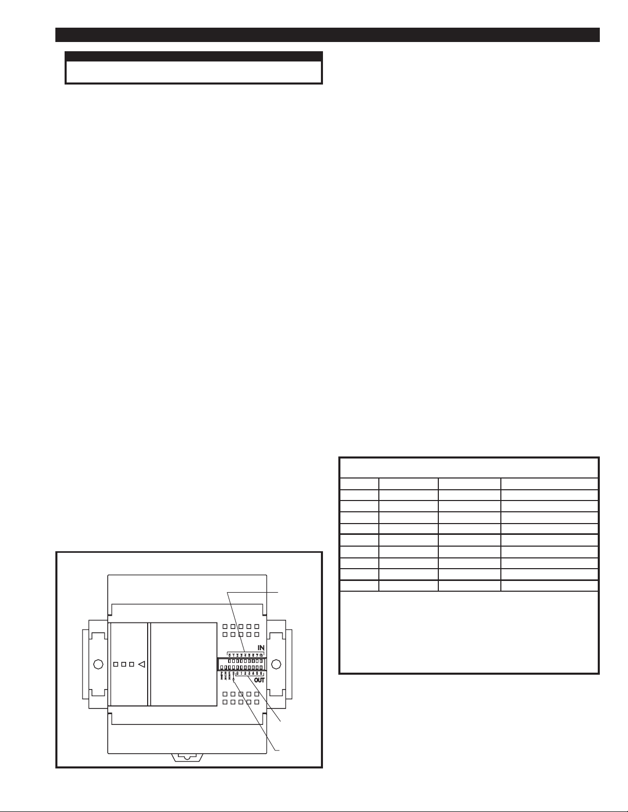
The PLC has power, run and error LEDs. If there is power to the
PLC, the power LED will be illuminated. If the power LED is not
illuminated, check the power supply to the PLC. If there is power
present, the PLC is faulty.
If the error LED is lighted, an error has occurred in the program
logic. Consult factory.
Reference Sections 11.5-2B and 11.5-2C for procedures to verify
that the input and output devices are operating properly. If the
devices are operating properly, the PLC will need to be replaced.
11.5-2B TESTING THE INPUT DEVICE
EMCOM II MODELS ONLY:
The PLC supplies a 24 volt DC signal to the input devices and alarm
contacts. If the input device is activated, it will cause that input LED
to light. The input LEDs are labeled 0 to 7.
The input devices can be easily tested for proper operation. With
power to the control box, set the Power ON/OFF Push-button (PB1)
to the OFF position, then the ON position. This should cause LED 0
to light. Pushing the failure to switch light (PB2) should cause LED 3
to light. Pushing the high humidity light (PB3) should cause LED 5 to
light. The fixed/auto selector switch can be tested as follows. In the
fixed mode, LED 6 should be off. In the auto mode, LED 6 should be
lighted. If these input devices do not function as described, they
should be replaced.
The pressure switches monitor the failure to switch option. The
inputs from the pressure switches (PS1, PS2) can be observed while
the dryer is in operation. Any time there is more than 30 psig
pressure in the left tower, pressure switch (PS1) should cause LED 1
to light. Any time there is more than 30 psig pressure in the right
tower, pressure switch (PS2) should cause LED 2 to light. If the
pressure switches do not respond as previously explained, replace
them.
To check input 4 or 7, follow the procedures in Section 11.5-9 for
calibrating the outlet humistat.
If the input devices are activated and LED is not illuminated, take a
voltage measurement across the input terminals. If the device is
faulty, it must be replaced. If the device is working properly, check
the wiring from the PLC. If the wiring and device are good, the PLC
is faulty and should be replaced. Reference Figure 11I DRYER
WIRING DIAGRAM for wiring and terminal numbers.
The run LED must be on for the PLC to operate. If the run LED is
off, turn the main power to the dryer off and on again. The PLC
should reset and the run LED should turn on. If the LED does not
turn on, consult factory.
If the power and run LEDs are on and the error LED off, the PLC
may still be faulty. To verify that the input and output of the PLC
are operating properly, the input and output devices must be
checked. Figure 11B lists the inputs and outputs on the PLC and the
corresponding devices.
FIGURE 11A PROGRAMMABLE CONTROLLER DETAIL
INPUT
LEDs
OUTPUT
LEDs
NOT
USED
FIGURE 11B INPUT AND OUTPUT LIST (EMCON II)
INPUT DEVICES
0 PB1
1 PS1
2 PS2
3 PB2
4 CDP1
5 PB3
6 SW1
7 CDP2
10 SPARE
NOTE:
The general alarm contact is a normally open dry contact which is wired to terminals #5 and
#6.
The lights are run off 120 volts AC which is reduced to 24 volts DC through resistors
and diodes on the printed circuit board.
The control relays (CR1, CR2, CR3) are mounted on the board which is mounted to the
back of the control box door. CR2 and CR3 are the control relays which give you the
general alarm contact.
OUTPUT DEVICES
0 SV1 & PL7
1 SV2 & PL8
2 SV3 & CR1
3 PL2 & CR2
4 PL3 & CR3
5 PL4
6 SPARE
11.5-2C TESTING THE OUTPUT DEVICES
EMCON II MODELS ONLY:
The microprocessor’s outputs are 120 volts AC. The output LEDs
are labeled 0 to 5. If the output’s LED is illuminated, that output is
supplying 120 volts AC to its component.
To check outputs 0 through 2, follow the procedures in Section
11.5-3.
PAGE 19
Page 20
MAINTENANCE & TROUBLESHOOTING SECTION 11
There is no easy way to check outputs 3 through 5. Output 3 can
be checked by causing a switching failure. Output 4 can be
checked by creating a false outlet dew point by setting the outlet
dew point humistat lower than the factory setting and allowing the
dryer to go into HIGH HUMIDITY ALARM. Output 5 can be
checked when either output 3 or 4 are checked. Before attempt-
ing this procedure, consult the factory.
11.5-3 CHECKIING THE 3-WAY PILOT VALVES
(SV1 & SV2) TOWER CHANGEOVER
All 3-way pilot valves have manual override buttons on the top of
the valve. To test SV1 and SV2 do the following:
For dryers with the Standard Control Box make sure the Stop button
is pressed and the dryer is pressurized. For dryers with Cycle Saver
or Emcon II Control Boxes make sure the Power switch is in the
OFF position and the dryer is pressurized. Both towers should be
at full line pressure Pushing the manual override of SV1 should
cause the left tower to depressurize. Allow the left tower to come
back up to full line pressure. Pushing the manual override of SV2
should cause the right tower to depressurize. If this does not
happen, replace that solenoid valve.
EMCON II MODELS ONLY:
With the Power push-button (PB1) in the on position, the fixed/auto
selector switch in the fixed mode, and the dryer pressurized,
monitor the outputs on the microprocessor. If output 0 is lighted,
SV1 should be activated, the left tower should be depressurized
and the right tower should be pressurized and drying the compressed air. If output 1 is lighted, SV2 should be activated, the
right tower should be depressurized and the left tower should be
pressurized and drying your compressed air. These two operations
can be monitored in one 10 minute fixed cycle.
If the above responses are not observed, first check to see if power
is being supplied to each solenoid valve when the corresponding
output LED on the PLC is lighted. Check the wiring between the
PLC and solenoid valves. If the PLC is not supplying power to the
valve when the LED is illuminated, replace the PLC. If the valve
has power but does not operate, it must be replaced.
With the dryer pressurized, the Power push-button in the ON
position, and the dryer in the fixed mode, remove the bleed orifice
from the tower dew point humistat’s sample cell. Monitor the air
flow from the sample cell for one complete 10 minute cycle. There
should be full line pressure coming from that sample cell for the
whole cycle. If air pressure to the sample cell is lost at any part of
the cycle, check the sample line filters and the solenoid valve
(SV3). Repair or replace as necessary.
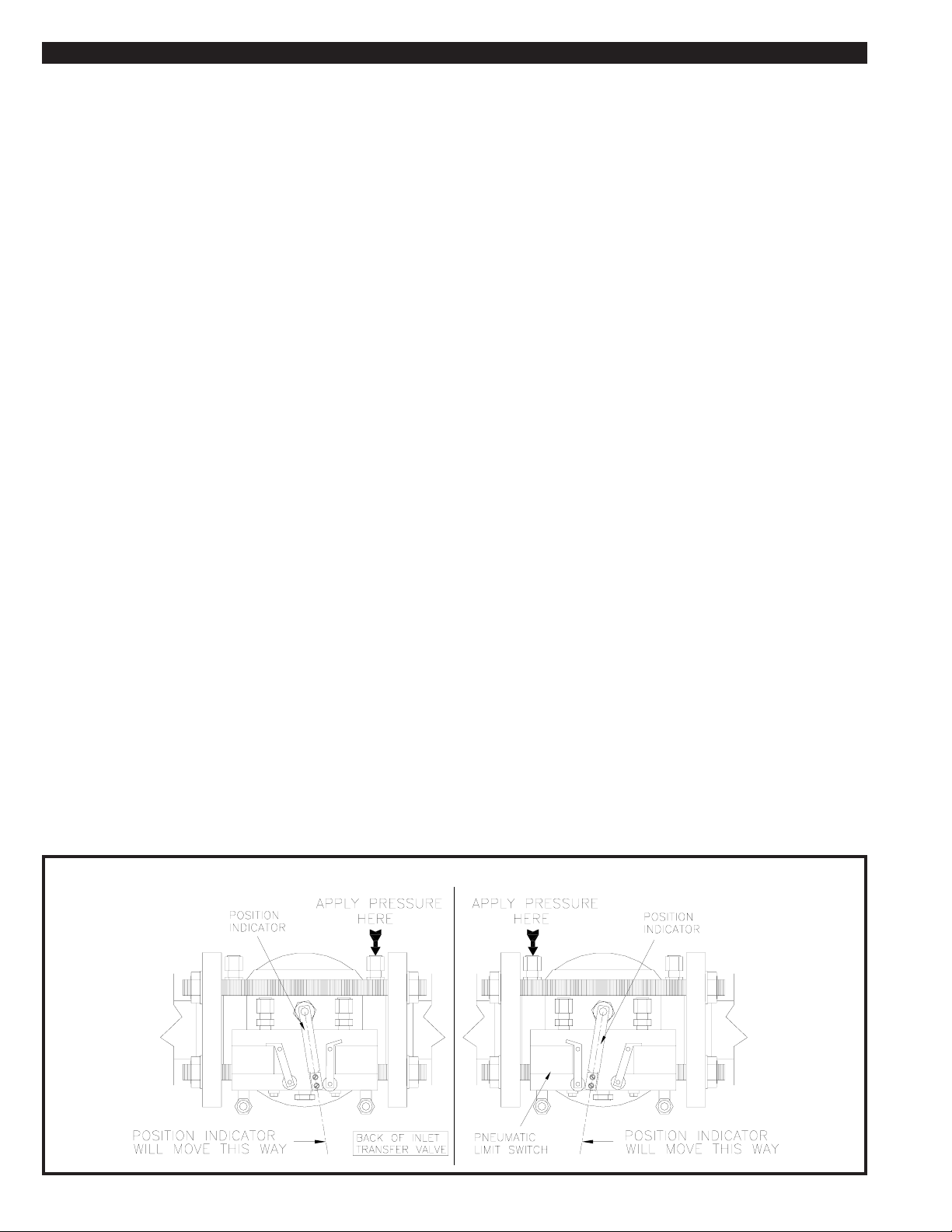
11.5-5 CHECKING THE INLET TRANSFER VALVE
The inlet transfer valve will not switch positions unless the pressure
in both desiccant towers is nearly equal. At tower changeover, the
regenerating tower should approach full line pressure before the
inlet valve will switch. Make sure that there are no leaks in the
piping or fittings. Make sure that the purge exhaust valves are
closing and that the purge metering valve is properly set.
The exhaust ports on top of the pilot valves (SV1 & SV2) should not
have air exhausting through them continuously. If air is exhausting
continuously through either of the exhaust ports, the inlet transfer
valve is faulty and should be rebuilt or replaced.
To test the inlet transfer valve for proper operation, turn off the
power, isolate and depressurize the dryer.
Remove the two pilot lines to the inlet valve. The pilot lines are
connected to the outside flanges of the valve. Using an air nozzle
and clean air, pressurize one of the ports. Observe the position
indicator. It should move in the direction of the port that is being
pressurized. No air should be exhausting from the other port.
Pressurize the other port. The valve should move to the other side.
If the valve does not move or air is being exhausted out of the port
that is not pressurized, the inlet transfer valve must be rebuilt or
replaced. Reference Section 12.6 for rebuild kit part numbers.
11.5-6 CHECKING THE PNEUMATIC LIMIT SWITCHES
Mounted on the inlet transfer valve is a set of 3-way pneumatic limit
switches. These switches control the pilot air to open and close the
purge exhaust valves.
11.5-4 CHECKING THE SOLENOID VALVE
(SV3) TOWER SAMPLE SELECT
CYCLE SAVER AND EMCON II MODELS ONLY:
Solenoid valve (SV3) is used to switch the sample line to the tower
that is on line drying your compressed air. It then feeds a sample of
air to the tower dew point humistat's sample cell.
FIGURE 13C INLET TRANSFER VALVE DETAIL
When a pneumatic limit switch is activated by the inlet transfer valve
position indicator, pilot air is supplied to the purge exhaust valve on
that side of the dryer.
To check the pneumatic limit switches, allow the dryer to cycle.
Check the pilot line to the purge exhaust valve on the side of the
activated limit switch. If no air is present, the limit switch must be
replaced. The limit switches are sold in sets only.
PAGE 20
Page 21
MAINTENANCE & TROUBLESHOOTING SECTION 11
11.5-7 CHECKING THE PURGE EXHAUST VALVES
The purge exhaust valves are normally closed. They can be checked
by removing the pilot air lines to them. The valves should be closed.
Using an air nozzle and clean air, pressurize the purge exhaust
valves. The valves should open when pressurized. If valve does not
open and close, it should be rebuilt or replaced. See Section 12.6 for
rebuilt kit part numbers.
11.5-8 CHECKING THE OUTLET CHECK VALVES
This dryer uses two check valves for outlet air control. If either of the
outlet valves fails, one of the following will occur:
• A large amount of air will purge from one tower
• The outlet air flow will be blocked
If either happens, the faulty check valve must be replaced.
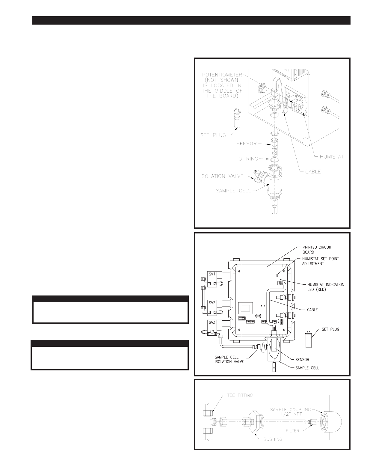
11.5-9 CALIBRATING THE HUMISTAT
CYCLE SAVER AND EMCON II MODELS ONLY:
The set point for the humistat is calibrated by a set plug.
Unplug the cable from the sample cell. Plug the set plug into the end
of the humistat cable.
For dryers equipped with the Cycle Saver Control Box turn the
humistat set point adjustment located on the printed circuit board until
the Humidity Indication LED is lit. This will calibrate the dew point
meter. Reference Figure 11E.
For dryers equipped with the Emcon II Control Box turn the potentiometer on the humistat board until you see the LED input light turn on.
This will calibrate the dew point meter. Reference Figure 11D.
If you get no response from the humistat set point adjustment or the
potentiometer with the set plug in, first check the cable connection. If
the cable and set plug are good, replace the printed circut board
(Cycle Saver) or the humistat board (Emcon II).
Re-install the filter. Carefully push the assembly back into the tower
and tighten the bushing into the coupling. DO NOT FORCE THE
ASSEMBLY. An application of pipe sealant to the bushing threads
may be necessary. Reconnect the line at the tee fitting.
FIGURE 11D HUMISTAT DETAIL FOR EMCON II
DRYERS EQUIPPED WITH EMCON II HAVE TWO HUMISTATS AND SAMPLE CELLS.
FIGURE 11E HUMISTAT DETAIL FOR CYCLE SAVER
NOTE
The sensor can be tested by removing it from the sample cell and
plugging it into the cable. With the sensor in the ambient air, the
humistat should turn on the corresponding LED. Place the sensor
back into the sample cell and allow compressed air to pass over it.
The LED for the humistat should turn off in several minutes if the air is
dry. If you get no response from the LED, replace the dew point
sensor.
CAUTION
NEVER USE AN OHMMETER TO CHECK THE SENSOR. THE
USE OF AN OHMMETER OR ANY ELECTRICAL TESTING
DEVICE WILL CAUSE DAMAGE TO THE SENSOR.
11.5-10 SAMPLE LINE MAINTENANCE
WARNING
DO NOT ATTEMPT TO REMOVE ANY FITTINGS UNTIL ALL AIR
PRESSURE IS OUT OF THE VESSEL. CHECK ALL TOWER
PRESSURE GAUGES, MAKING SURE THAT THEY ARE AT
0 PSIG AND THE DRYER IS ISOLATED.
Take dryer off stream following the SHUTDOWN PROCEDURES IN
SECTION 10.
Disconnect the sample line at the tee fitting.
Unthread the sample line from the tower at the bushing. Carefully pull
the sample line assembly from the tower. Some desiccant will drain
from the tower. Plug the coupling to prevent more desiccant from
draining.
FIGURE 11F SAMPLE LINE DETAIL
Unthread the sample line filter from the tubing. Clean or replace the
filter. The filter is made of sintered bronze material. To clean it, use
pressurized, clean air.
PAGE 21
Page 22
MAINTENANCE & TROUBLESHOOTING SECTION 11
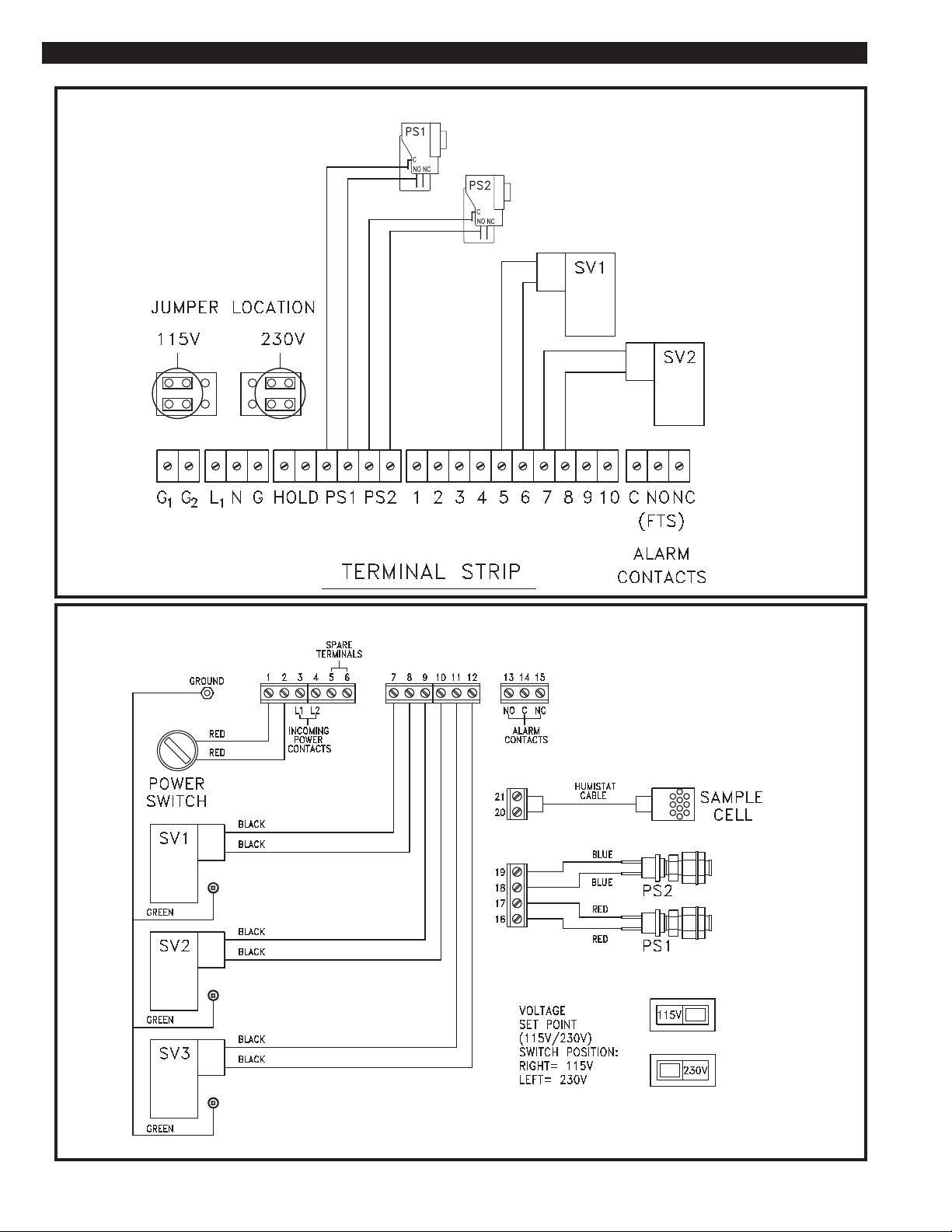
11.6 WIRING DIAGRAMS
FIGURE 11G WIRING DIAGRAM for STANDARD CONTROL
FIGURE 11H WIRING DIAGRAM for CYCLE SAVER
PAGE 22
Page 23
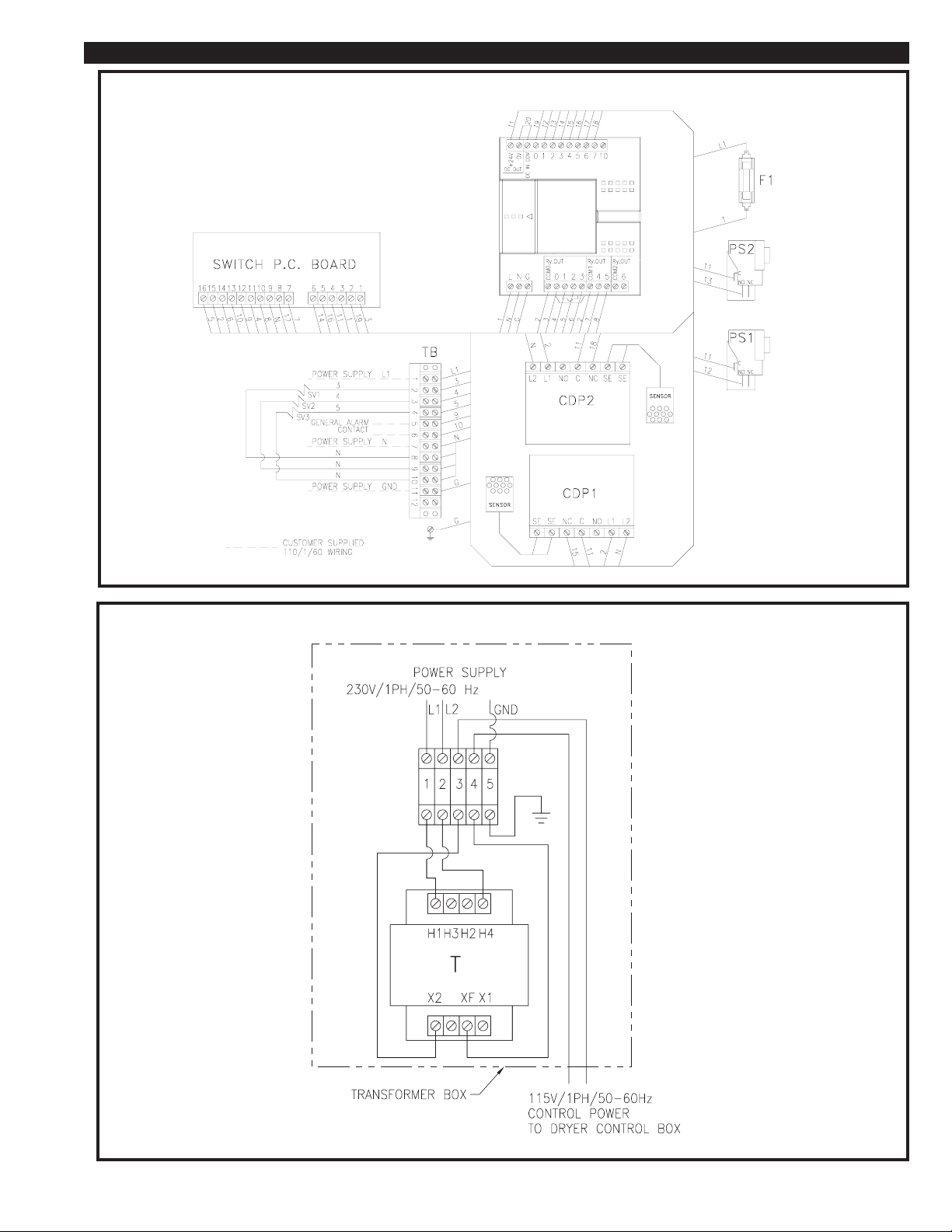
MAINTENANCE & TROUBLESHOOTING SECTION 11
FIGURE 11I WIRING DIAGRAM for EMCON II
FIGURE 11J WIRING DIAGRAM for OPTIONAL 230 VOLT TRANSFORMER BOX
PAGE 23
Page 24
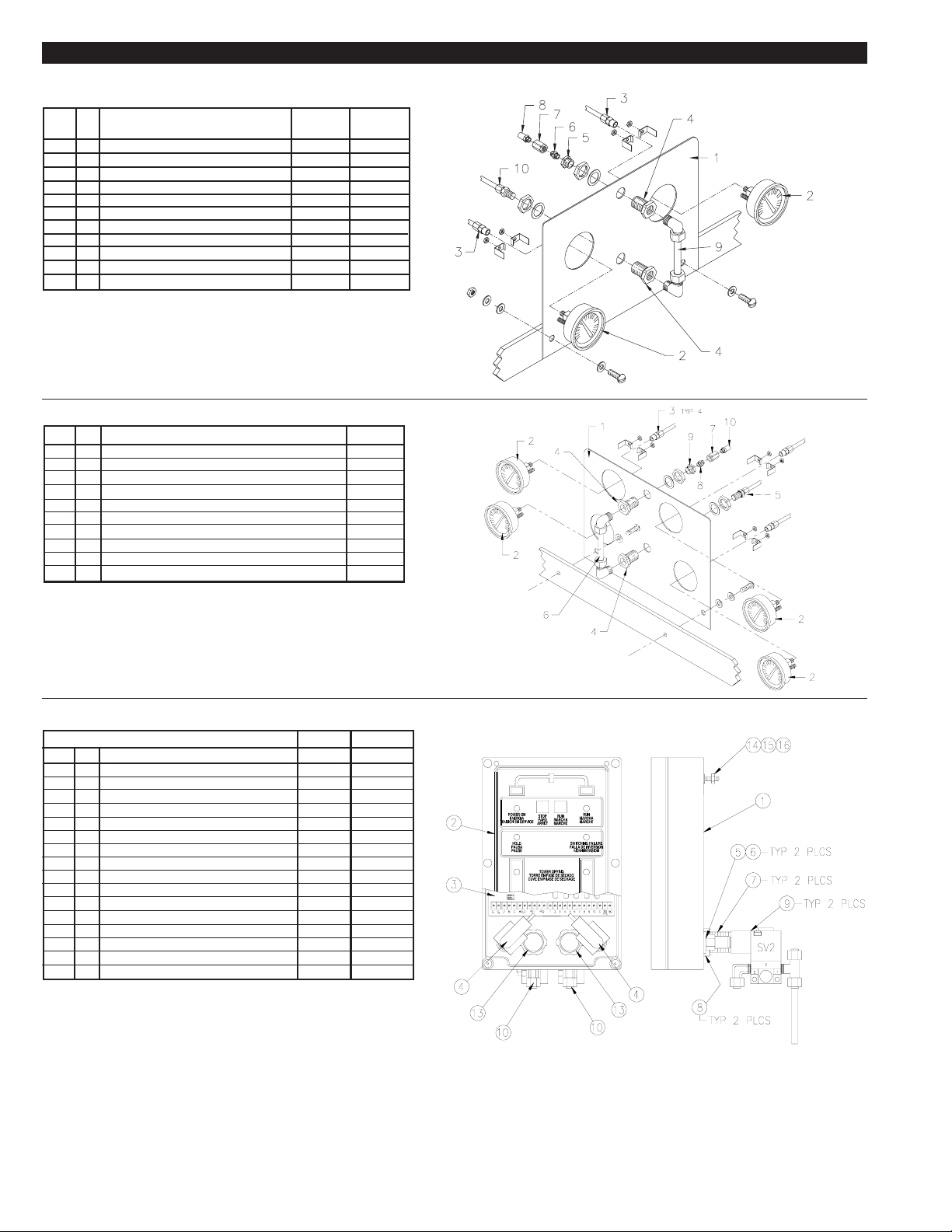
REPLACEMENT PARTS SECTION 12
12.1 STANDARD CONTROL AND CYCLE SAVER GAUGE PANEL REPLACEMENT
PARTS
ITEM
1
2
3
4
5
6
7
8
9
10
QTY
Panel
1
2" Pressure Gauge, 0-200 PSIG
2
1/8" NPT x 1/4" Female Straight Tube Fitting
2
1/4" NPT Anchor Tube Fitting
2
1/4" NPT x 10-32 Reducer Bushing
1
10-32 Short Coupling
1
10-32 Choke Fitting
1
10-32 Sintered Filter
1
Visible Moisture Indicator Assembly
1
1/4" NPT x 1/4" Male Straight Tube Fitting
1
DESCRIPTION
STANDARD
CONTROL
PART NO.
26-6487
29-0278
26-0233
26-1497
26-0296
26-0657
26-0490
26-0623
46-2300
26-0231
CYCLE
SAVER
PART NO.
26-5654
29-0278
26-0233
26-1497
26-0296
26-0657
26-0490
26-0623
46-2300
26-0231
12.2 EMCON II GAUGE PANEL REPLACEMENT PARTS
ITEM
1
2
3
4
5
6
7
8
9
10
QTY
Panel
1
2" Pressure Gauge, 0-200 PSIG
4
1/8" NPT x 1/4" Female Straight Tube Fitting
4
1/4" NPT Anchor Tube Fitting
2
1/4" NPT x 1/4" Male Straight Tube Fitting
1
Visible Moisture Indicator Assembly
1
10-32 Choke Fitting
1
10-32 Short Coupling
1
1/4" NPT x 10-32 Reducer Bushing
1
10-32 Sintered Filter
1
DESCRIPTION
PART NO.
26-5655
29-0278
26-0233
26-1497
26-0231
46-2300
26-0490
26-0657
26-0296
26-0623
12.3 STANDARD CONTROL SYSTEM REPLACEMENT PARTS
ITEM
1
2
3
4
5
6
7
8
9
10
11
12
13
14
15
16
QTY
1
Enclosure
1
Panel Membrane and Ribbon Connector
1
Circut Board
2
Pressure Switch
2
Female Connector Fitting
2
Threaded Seal Fitting
2
1/2" NPT x 2" LG Close Nipple, Galvanized
2
Seal Fitting
2
1/8" Solenoid Valve
3
Male Elbow Tube Fitting
1
Male Tee Tube Fitting
1/4 ft.
Nylon Tubing 1/4" Outside Diameter
2
1/2"Connector Locknut
1
8-32 Washer Stat-O-Seal
1
8-32UNF x 1" LG Rd Mach Grounding Screw
1
8-32UNF Hex Nut
DESCRIPTION
115V
PART NO.
27-1139
26-6356
26-6469
26-5284
26-6492
26-3042
12-0515
26-0883
14-2082
26-0234
26-0504
26-0223
26-6491
28-1371
28-1372
28-1373
230V
PART NO.
27-1139
26-6356
26-6469
26-5284
26-6492
26-3042
12-0515
26-0883
14-2083
26-0234
26-0504
26-0223
26-6491
28-1371
28-1372
28-1373
PAGE 24
Page 25
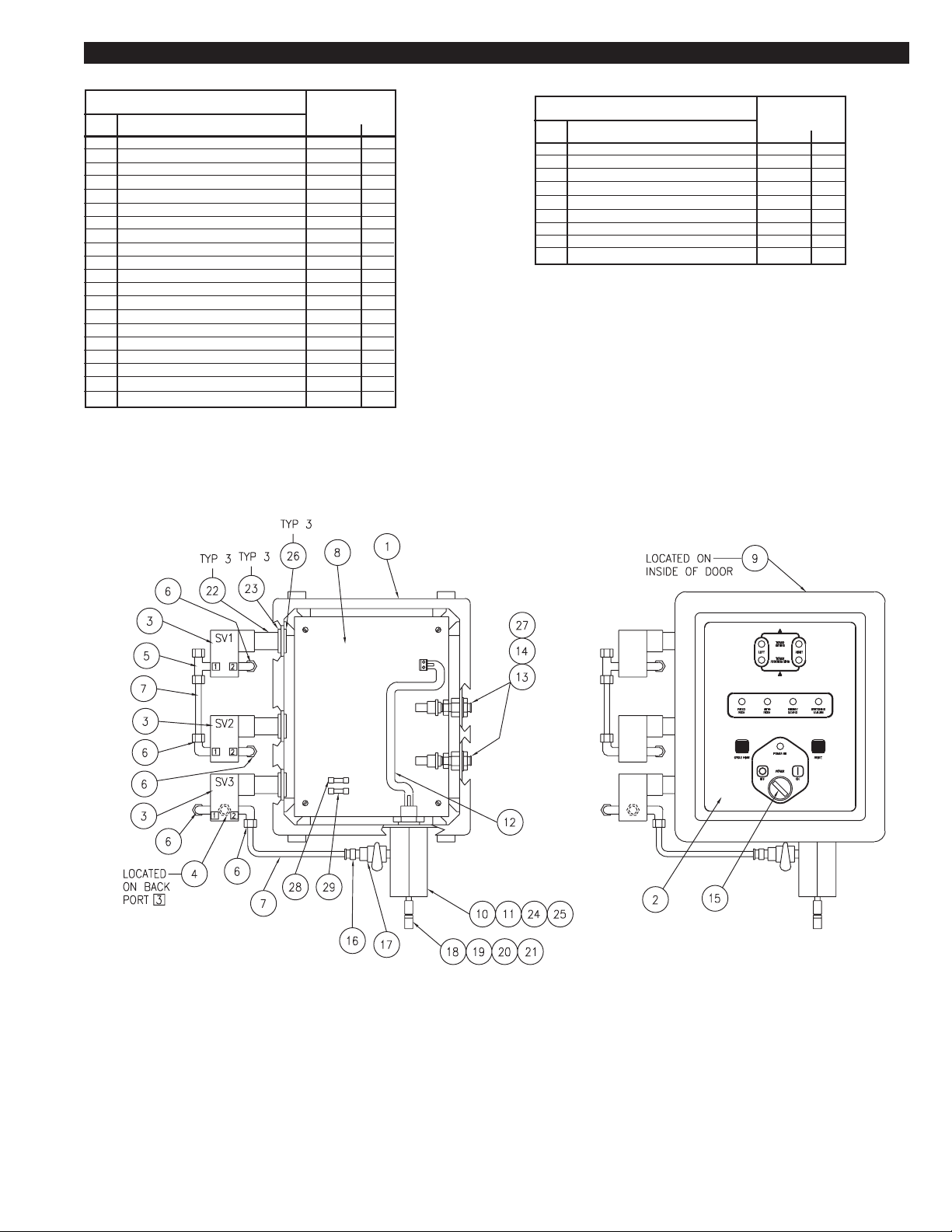
REPLACEMENT PARTS SECTION 12
12.4 CYCLE SAVER CONTROL REPLACEMENT PARTS
ITEM
1
Enclosure
2
Label (Cycle Saver)
3
1/8" NPT Solenoid Valve
4
Male Connector Fitting
5
Male Tee Tube Fitting
6
Male Elbow Tube Fitting
7
Nylon Tubing 1/4" Outside Diamater
8
PC Mother Board
9
PC Display Board
10
Sample Cell Manifold
11
Sensor
12
Cable
13
Pressure Switch
14
Bulkhead Fitting
15
Switch (On/Off)
16
Male Connector Fitting
17
Dew Point Isolation Valve
18
10-32 Choke Fitting
19
10-32 Short Coupling
20
1/4" x 10-32 Reducer Fitting
DESCRIPTION
CYCLE SAVER
PART NO.
27-1141
30-1391
14-1721
26-0639
26-0504
26-0234
26-0223
26-6501
26-6502
26-6503
26-0817
26-6505
26-6471
26-6472
26-6507
26-2142
14-2110
26-0490
26-0657
26-0296
QTY
1
1
3
1
1
5
1/2 ft.
1
1
1
1
1
2
2
1
1
1
1
1
1
ITEM
21
10-32 Sintered Filter
22
1/2" x 2" LG, Conduit Nipple
23
Seal Nut
24
Sensor Pin Insert
25
Washer
26
Ground Lock Nut
27
Washer (Phoenix)
28
Fuse 1- 6/10 Amp
29
Fuse 1/8 Amp
DESCRIPTION
CYCLE SAVER
PART NO.
26-0623
12-1876
26-6512
26-6504
26-6508
26-6511
26-6525
26-6527
26-6528
QTY
1
3
3
1
1
3
1
1
1
PAGE 25
Page 26
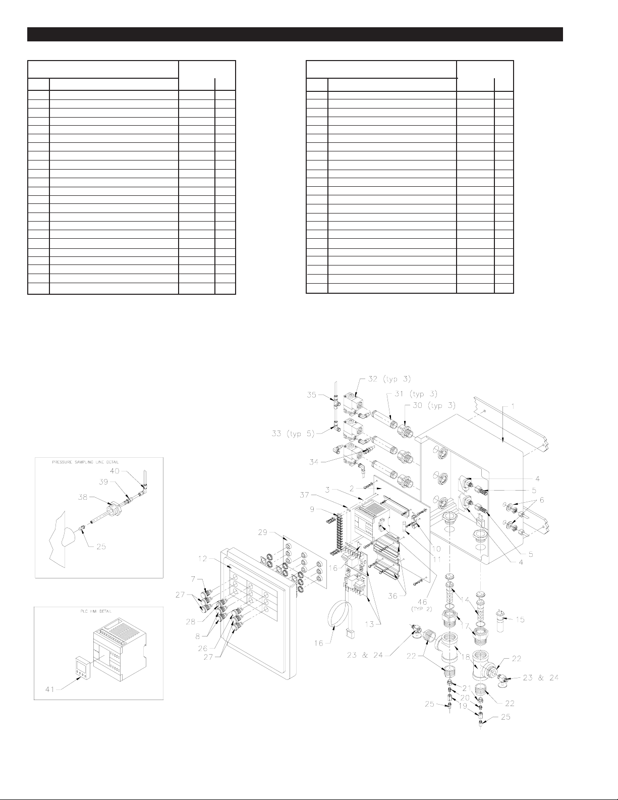
REPLACEMENT PARTS SECTION 12
12.5 EMCON II CONTROL REPLACEMENT PARTS
ITEM
1
Fiberglass Enclosure
2
Back Panel
3
Programmable controller (programmed)
4
Pressure Switch
5
Bulkhead Female Tube Fitting
6
Thread Seal
7
Lighted Push-button (white)
8
Lighted Push-button (red)
9
Terminal Block
10
Fuse Block
11
Fuse 2 amp
12
Box Label
13
Humistat
14
Sensor
15
Set Plug
16
Cable
17
Threaded Mount For Sensor
18
1" NPT Tee, Galvanized
19
10-32 Choke Fitting
20
10-32 Short Coupling
21
1/4" x 10-32 Reducer Bushing
22
1" NPT x 1/4" NPT Hex Bushing
23
Needle Valve 1/4" Tube Fitting
DESCRIPTION
EMCON II
PART NO.
27-1081
27-1082
46-3296
26-5284
26-3127
26-3042
26-5621
26-5622
26-5623
26-5624
26-5625
30-1320
26-0814
26-0817
26-0818
46-2185
26-0816
14-1807
26-0490
26-0657
26-0296
14-1808
14-1306
QTY
1
1
1
2
2
2
1
2
1
1
1
1
2
2
1
2
2
2
2
2
2
4
2
ITEM
1/4" Nut And Sleeve Tube Fitting
24
10-32 Sintered Filter
25
Light (green)
26
Light (yellow)
27
Switch
28
Door Component Circuit Board
29
1/2" Conduit Hub Connector
30
1/2" NPT Close Nipple
31
3-Way Solenoid Valve
32
1/8" NPT x 1/4" Male Elbow Tube Fitting
33
1/8" NPT x 1/4" Male Straight Tube Fitting
34
1/8" NPT x 1/4" Male Branch Tee Tube Fitting
35
Snap Track Mounting Strip
36
Terminal Strip Marker
37
1/2" NPT x 1/4"" NPT Bushing
38
1/4" NPT Thermocouple Fitting
39
1/4" Union Elbow Tube Fitting
40
HMI Module Kit
41
Replacement LED, white
42
Replacement LED, red
43
Replacement LED, yellow
44
Replacement LED, green
45
Mounting Clip for PLC
46
DESCRIPTION
EMCON II
PART NO.
26-3043
26-0623
26-5628
26-5632
26-5629
26-5633
26-3662
12-1668
14-1721
26-0234
26-0369
26-0504
26-5664
26-5762
14-0441
26-0862
26-0416
46-3326
26-5783
26-5786
26-5784
26-5785
26-6884
QTY
2
4
1
4
1
1
3
3
3
5
1
1
2
1
2
2
2
1
1
2
4
1
2
PAGE 26
Page 27
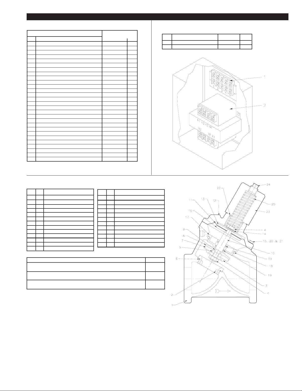
REPLACEMENT PARTS SECTION 12
12.6 REPLACEMENT P A RTS
ITEM
Inlet Transfer Valve
1
a
Seat & Seal Kit for Inlet Transfer Valve
b
Position Indicator Kit for Inlet Transfer Valve
c
Shuttle Assembly Kit for Inlet Transfer Valve
2
Check Valve
3
Purge Valve
Diaphragm & Seal Kit for Purge Valve
a
b
Internal Repair Kit for Purge Valve
c
Spring Kit for Purge Valve
4
Gasket 3"
5
Sintered Filter
6
Purge Exhaust Muffler
Element, purge exhaust muffler
7
a
Control Air Filter
8
Element, control air filter
a
Purge Metering Valve
9
Pneumatic Limit Switch (set)
10
Manifold Block w/Pneumatic Limit Switches
Desiccant drain plug
11
12
Gasket 4"
13
Gasket for 12 x 16 hatch cover
14
Hatch cover 12 x 16 (painted)
15
Desiccant
Activated Alumina, 1/8" dia, 25# pail
Activated Alumina, 1/8" dia., 50# bag
Activated Alumina, 1/8" dia., 375# drum
16
Touch-Up Paint, 9oz. spray can
17
OPTIONAL SAFETY RELIEF VALVE
DESCRIPTION
HL-2500
PART NO.
14-0945
26-0644
26-1055
26-1040
14-1868
14-1832
26-6024
26-6026
26-6031
18-0227
26-1014
26-0366
26-5777
26-6830
26-6831
26-0359
14-0797
14-1037
14-1534
18-0208
18-0214
46-3285
33-0237
n/a
33-0320
45-0201
14-0990
QTY
1
1
1
1
2
2
2
2
2
4
1
2
4*
1
1
1
1
1
2
8
2
2
-
11
n/a
7
1
2
12.7 OPTIONAL 230 VOLT TRANSFORMER
ITEM
1
2
DESCRIPTION
Terminal Strip
Transformer
PART NO.
26-0250
26-5751
QTY
1
1
* Quantity of 4 required per muffler
12.8 3" PURGE VALVE
ITEM
QTY
1
1
2
1
3
1
4
2
5
1
6
1
7
1
8
1
9
2
10
1
11
1
12
1
13
1
DIAPHRAM & SEAL KIT
Consists of Item Numbers: 4(2), 6, 7, 9(2), 11, 14, 18 & 19(2)
INTERNAL REPAIR KIT
Consists of Item Numbers: 3, 5, 8, 10, 13, 16 & 17 and "DIAPHRAGM AND SEAL KIT "
SPRING KIT
Consists of Item Number: 25
* Disc is directional and should be installed with 3/64 smooth nitrile coating
towards seat (away from disc holder)
DESCRIPTION
Body 3" Flanged
Seat (cast brass)
Disc Plate
Hex Lock Nut (5/16-24)
Disc Spacer (brass)
O-Ring (viton)
Disc (hycar)*
Disc Holder (brass)
O-Ring (viton)
Shaft
Diaphragm
Cap (cast iron)
Upper Diaphragm Plate
REPAIR KITS
ITEM
14
15
16
17
18
19
20
21
22
23
24
25
QTY
1
Lockwasher Set
2
Hex HD. Cap Screw (3/8-16 x 7/8)
1
Lower Diaphragm Plate
1
O-Ring Retainer (brass)
1
O-Ring (viton)
2
O-Ring (AFLAS)
6
Hex HD. Cap Screw (3/8-16 x 1-1/2)
6
Hex Nut (3/8-16)
1
Gasket (copper)
1
Retainer Nut
1
Square Head Plug 1/8" NPT
1
Spring
DESCRIPTION
PART NO.
26-6024
26-6026
26-6031
12.9 HOW TO ORDER PARTS
To order parts for your dryer contact your local VAN AIR representative or the representative where you purchased the dryer from. If you cannot
find a local representaitve or have problems ordering the parts, contact the factory.
When contacting your local VAN AIR representative or the factory, the following information is necessary:
Dryer model
Dryer serial number
Dryer part number
This information can be found on the dryer data tag. The data tag is located inside the door of the control box.
The Service Department can be reached by calling 888-606-9303 or faxing 814-774-3482. Hours are 8:00 AM EST to 5:00 PM EST, Monday through
Friday.
PAGE 27
Page 28
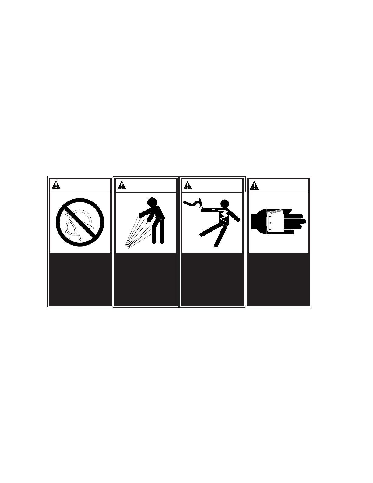
Safety is everybody's business and is based on your use of good common sense. All situations or circumstances cannot
SAFETY PRECAUTIONS
always be predicted and covered by established rules. Therefore, use your past experience, watch out for safety hazards
and be cautious.
DANGER
DISCHARGE AIR USED FOR
BREATHING WILL CAUSE SEVERE
INJURY OR DEATH. CONSULT
FILTRATION SPECIALIST FOR
ADDITIONAL FILTRATION AND
TREATMENT EQUIPMENT TO
MEET HEALTH AND SAFETY
REGULATIONS.
DANGER
AIR AND OIL UNDER PRESSURE
WILL CAUSE SEVERE
PERSONAL INJURY OR DEATH.
SHUT DOWN COMPRESSOR AND
RELIEVE SYSTEM OF ALL
PRESSURE BEFORE REMOVING
VALVES, CAPS, PLUGS,
FITTINGS, BOLTS AND FILTERs.
W ARNING
ELECTRICAL SHOCK FROM
IMPROPER GROUNDING CAN
CAUSE INJURY OR DEATH.
GROUND UNIT AND RELATED
EQUIPMENT ACCORDING TO
NATIONAL ELECTRICAL CODE
AND LOCAL REGULATIONS.
W ARNING
READ THE OPERATOR'S
MANUAL BEFORE STARTING OR
SERVICING THIS UNIT. FAILURE
TO ADHERE TO INSTRUCTIONS
CAN RESULT IN SEVERE
PERSONAL INJURY OR DEATH.
REPLACEMENT MANUALS CAN
BE PURCHASHED BY
CONTA CTING THE
MANUFACTURER.
PAGE 28
 Loading...