

Page 1
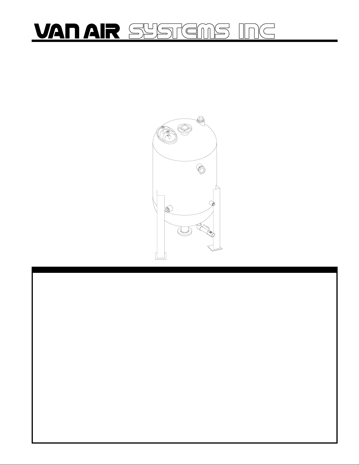
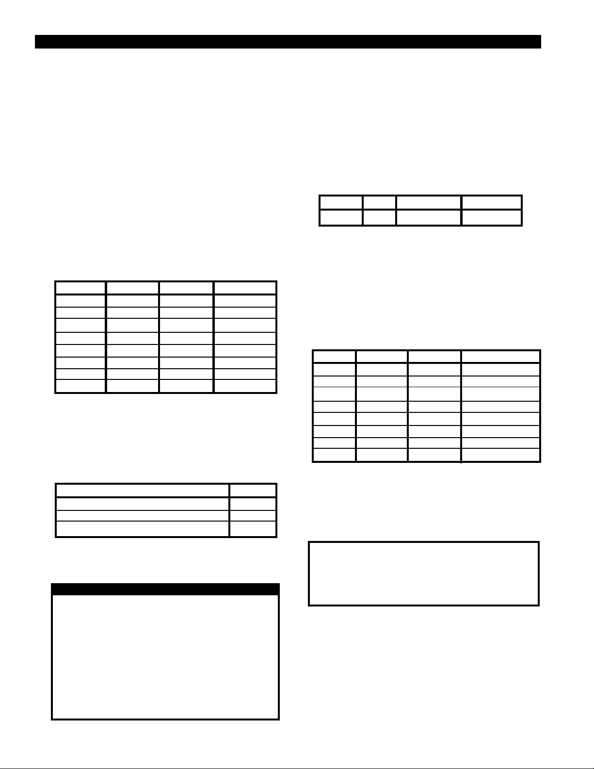
p/n 32-0120 rev D
INSTALLATION, OPERATION, & MAINTENANCE INSTRUCTIONS
FOR
SINGLE TOWER
COMPRESSED AIR DRYER
MODELS
D-42 through D-84
MARCH 2005
WARNING
DO NOT REMOVE, REPAIR, OR REPLACE ANY ITEM ON THE
DRYER WHILE IT IS UNDER PRESSURE. DEPRESSURIZE THE
DRYER COMPLETELY BEFORE STARTING INSTALLATION AND/
OR MAINTENANCE PROCEDURES. SERIOUS PERSONAL
INJURY MAY RESULT IF THESE SAFETY RULES ARE NOT
FOLLOWED.
DO NOT OPERATE THIS PRESSURE VESSEL ABOVE MAXIMUM
WORKING PRESSURE (MWP) AT MAXIMUM OPERATING
TEMPERATURE (OF) AS SHOWN ON THE ASME DATA PLATE.
THIS ASME CODE VESSEL MUST BE PROTECTED BY A
PRESSURE RELIEF VALVE. Refer to OSHA 1910.169 Par. b,
Sub. Par (3) and ASME Boiler and Pressure Vessel Code,
Section VIII, Division 1, UG-125 through UG-136. Also check
government regulations, i.e., state and local codes.
DO NOT WELD, GRIND, OR SAND VESSEL, OR IT WILL NOT
BE SAFE TO OPERATE. (Note: Any alteration to the vessel
will void the ASME Code Certification and the warranty.)
ANY DAMAGE TO THE VESSEL CAN MAKE IT UNSAFE.
INSPECT OUTSIDE AND INSIDE OF VESSELS REGULARLY
FOR BULGES, CORROSION, DENTS, GOUGES, LEAKS OR
SIGNS OF FIRE. IF DAMAGED, TAKE OUT OF SERVICE
IMMEDIATELY AND NOTIFY YOUR CERTIFYING AUTHORITY.
USE THE PROPER SAFETY RULES FOR THE GAS BEING
PROCESSED.
DO NOT REMOVE THE HATCH COVER UNTIL ALL AIR
PRESSURE IS OUT OF THE VESSEL. PUSH ON THE HATCH
COVER BY HAND TO FIND OUT IF THE VESSEL PRESSURE IS
REDUCED TO ZERO.
DO NOT TRY TO TIGHTEN THE HATCH COVER IF YOU HEAR
OR FEEL A LEAK. IMMEDIATELY SHUT OFF THE AIR OR GAS
SUPPLY TO THE VESSEL AND REDUCE THE DRYER
PRESSURE TO ZERO.
ALWAYS INSTALL A NEW GASKET EVERY TIME THE HATCH
COVER IS REMOVED, OR AT LEAST ONCE PER YEAR.
REPLACE THE HATCH COVER EVERY FIVE YEARS
REGARDLESS OF CONDITION. USE VAN AIR AUTHORIZED
PARTS ONLY.
DO NOT USE POWER TOOLS OR CHEATER BARS TO
TIGHTEN THE NUT ON THE COVER. TOO MUCH FORCE CAN
DISTORT THE COVER AND/OR THE GASKET. IF DAMAGED
BY OVERTIGHTENING, THE COVER CAN BLOW OUT AND
CAUSE SERIOUS INJURY. (Note: Tighten the nut until it is
snug only. When pressure is in the vessel, the seal will be
complete.)
INSPECT THE COVER AND SEALING SURFACE EVERY TIME
THE COVER IS REMOVED, OR AT LEAST ONCE PER YEAR,
FOR DAMAGE SUCH AS CORROSION, CRACKS, OR
DISTORTION. IF THERE IS ANY DAMAGE, INSTALL A NEW
COVER AND GASKET. USE VAN AIR AUTHORIZED PARTS
ONLY.
PAGE 1
Page 2
SECTION 1 INTRODUCTION
1.0 PURPOSE OF OPERATION
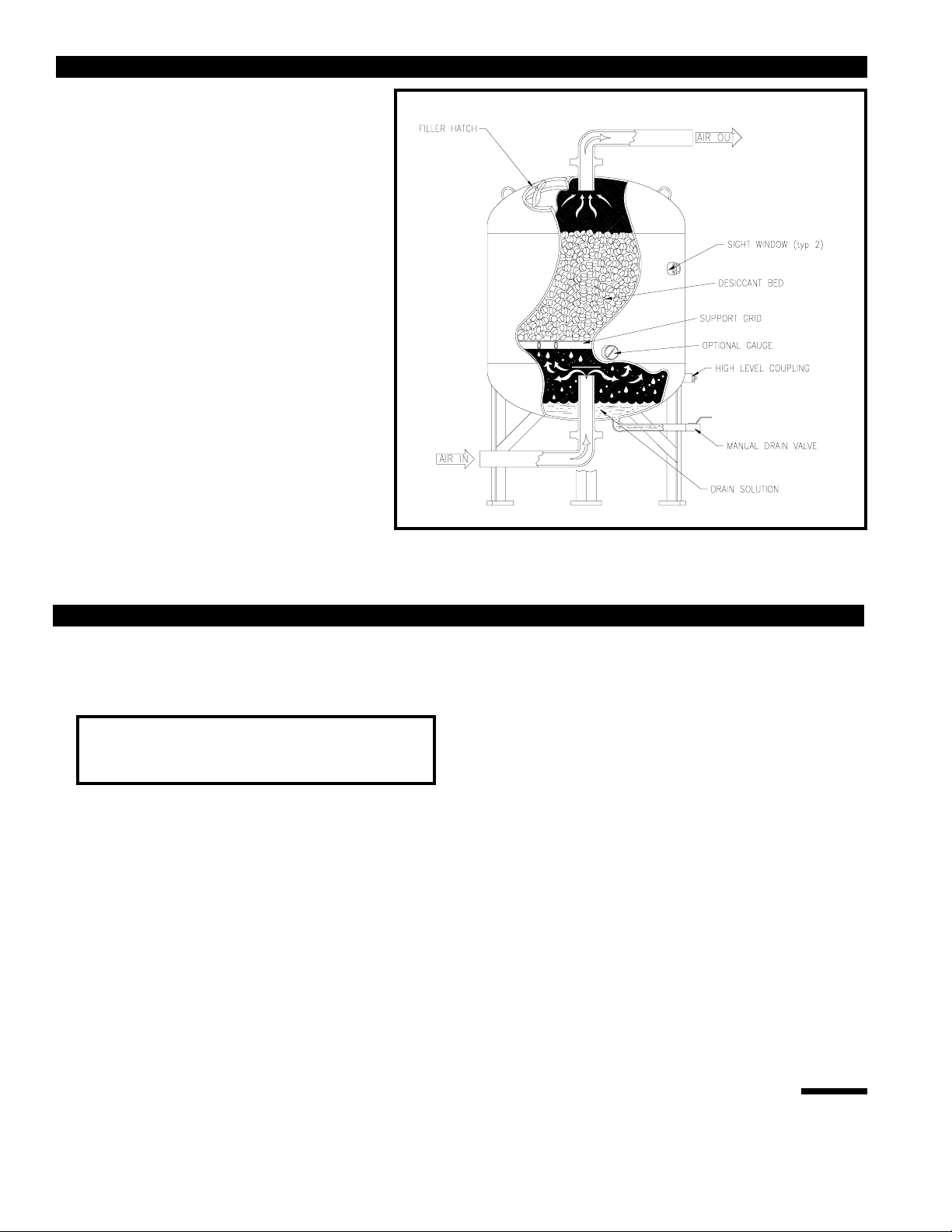
The purpose of installing a Van Air single tower dryer in
a compressed air system is to remove the water vapor
(humidity) which has been drawn into the system at the
compressor intake. The Van Air process dries the air as
it flows through the vessel, which is filled with a special
drying agent. The dryer operates automatically. There
are no moving parts and no external source of power is
required. If an automatic drain is installed, a power
source is required only to operate the valve.
The wet air enters the centrally located inlet which
channels the flow into the lower portion of the dryer.
Liquid water and solid particles are separated by gravity
and fall to the bottom of the vessel.
The process air moves upward through the bed of
desiccant tablets which attract and absorb the moisture
from the air before it flows through the dryer outlet. The
tablets dissolve gradually as they absorb the moisture.
The tablets create a structured bed that does not crush
under its own weight. In the bed of an operating dryer,
the lower tablets are consumed first.
The tablets in the top portion are virtually unused and
serve as a reserve supply. When the reserve supply is
depleted, the dryer must be refilled to maintain
performance.
The solution, which consists of dissolved desiccant and water, falls
into the claim area at the bottom of the vessel. The dryer must be
FIGURE 1 DRYER DETAILS
drained at least once each shift to remove the accumulated solution.
SECTION 2 INSTALLATION
2.1 LOCATION
The ability of a dryer to provide dry compressed air depends on the
correct location of the unit. Inlet air temperature and pressure are the
keys to selecting the proper location.
IMPORTANT
ALWAYS PROCESS AIR THROUGH THE DRYER AT THE
LOWEST POSSIBLE TEMPERATURE AND THE HIGHEST
PRACTICAL PRESSURE.
2.1-A INLET AIR TEMPERATURE
The dew point of the outlet air is directly related to the inlet air
temperature and the type of desiccant being used. The lower the inlet
temperature, the lower the dew point of the outlet air. Determine the
lowest ambient temperature where the compressed air is used or
where the lines are located. If you are using DRY-O-LITE or 10BF
desiccants, do not exceed 100oF inlet air temperature. If you are
using SP desiccant, do not exceed 80oF inlet air temperature.
2.1-B AFTERCOOLING
Air discharged by the compressor is extremely hot (from 150oF to
350oF). An aftercooler, finned tubing or extended run of piping will
usually be necessary to reduce the inlet air temperature to the dryer.
area. When air equipment or piping is located in an air conditioned
area, install the dryer in the coolest area--usually the air conditioned
area.
2.1-E AIR RECEIVER
In relation to the air receiver, the Van Air single tower dryer should
be located where it will be provided with the coolest inlet temperature.
If the receiver is located in an area where the ambient temperature
is lower than the outlet air from the aftercooler, locate the dryer
downstream of the receiver to allow additional cooling of the air
before it enters the dryer. (Exception: In systems where usage
creates sudden demands on the air supply, locate dryer before the
receiver to minimize air surges through the dryer.) If the ambient
temperature around the receiver is higher than the outlet air
temperature from the aftercooler, locate the dryer between the
aftercooler and the receiver.
2.1-F SPECIAL EQUIPMENT INSTALLATION
If the Van Air Dryer is being installed on a branch line to protect a
specific piece of air-operated equipment, locate the dryer on the high
pressure side of any pressure regulators.
2.1-G OPERATING PRESSURE
2.1-C OUTDOOR AIR USAGE
If some or all of the air supplied by the Van Air single tower dryer will
be used outdoors, install the dryer outdoors in the coolest possible
area. Make sure that the dryer is not exposed to ambient temperatures
below the minimum design temperature stamped on the vessel data
tag. When the dryer will be exposed to the direct rays of the sun,
install a sun shield to protect it (i.e. a roof).
2.1-D INDOOR AIR USAGE
If all of the air from the dryer will be used indoors where temperatures
remain within a fixed range, locate the dryer in the coolest indoor
PAGE 2
More air can be processed through the dryer at higher pressures.
Locate the dryer at the highest practical pressure, but do not exceed
the maximum rated working pressure of the dryer. Refer to the
capacity chart located on Page 3 for the maximum working pressure
for your dryer.
2.2 PIPING AND ANCILLARY EQUIPMENT
Locate the dryer in the proper location as explained in the previous
section.
If the dryer is being installed in an existing piping system, make sure
that the pipe is free of scale and rust.
Page 3
SECTION 2 INSTALLATION
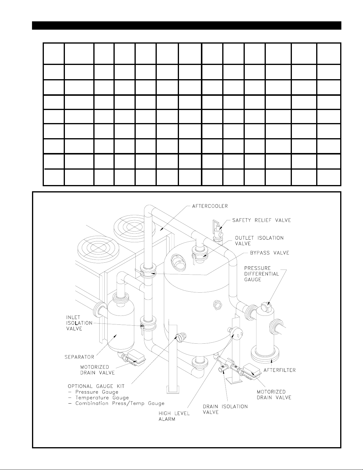
FIGURE 2 MAXIMUM CAPACITIES -SCFM (Nm3/hr)
MAXIMUM
378
642
454
771
605
756
908
40 PSIG
2.8 Bar
596
1013
715
1215
954
1620
1192
2026
1431
2431
1669
2836
1908
3241
2146
3646
50 PSIG
3.4 Bar
705
1198
846
1438
1128
1917
1410
2396
1692
2875
1974
3354
2256
3833
2538
4313
60 PSIG
4.1 Bar
814
1383
977
1660
1303
2213
1628
2766
1954
3319
2279
3873
2605
4426
2931
4979
80 PSIG
5.5 Bar
1032
1753
1238
2104
1651
2805
2064
3507
2477
4208
2890
4910
3303
5611
3715
6312
90 PSIG
6.2 Bar
1141
1939
1369
2326
1826
3102
2282
3877
2738
4653
3195
5428
3651
6203
4108
6979
100 PSIG
6.9 Bar
1250
2124
1500
2549
2000
3398
2500
4248
3000
5097
3500
5947
4000
6796
4500
7646
125 PSIG
8.6 Bar
1522
2587
1827
3104
2436
4139
3045
5173
3654
6208
4263
7243
4872
8277
5481
9312
150 PSIG
10.3 Bar
1795
3050
2154
3659
2872
4879
NO.
D-42
D-48
D-54
D-60
D-66
D-72
D-78
D-84
WORKING
PRESSURE
150 PSIG
150 PSIG
150 PSIG
125 PSIG
125 PSIG
125 PSIG
125 PSIG
125 PSIG
5 PSIG
0.3 Bar
215
365
258
438
344
584
429
730
515
875
601
1021
687
1167
773
1313
10 PSIG
0.7 Bar
269
457
323
549
431
732
538
915
646
1098
754
1281
861
1463
969
1646
20 PSIG
1.4 Bar
1028
1285
1542
1059
1799
1210
2056
1361
2313
MODEL
FIGURE 3 RECOMMENDED INSTALLATION DRAWING
NOTE:
ITEMS CALLED OUT IN THIS DRAWING ARE NOT SUPPLIED WITH THE DRYER. REFERENCE FIGURES 1 & 4
FOR ITEMS INCLUDED WITH DRYER.
PAGE 3
Page 4
SECTION 2 INSTALLATION
2.2-A INLET AND BYPASS PIPING
Using Figure 3 as a reference, make the necessary piping
connections into the dryer.
Inlet and outlet isolation valves should be installed on the dryer.
These valves will aid in the start up and shutdown of the dryer.
A bypass valve and piping should also be installed. This will allow
the dryer to be taken off stream without interrupting the air system.
2.2-B OPTIONAL PRESSURE RELIEF VALVE
A pressure relief valve should be installed to conform to OSHA
safety standards. Refer to OSHA Standard Section 1910.169,
paragraph b, subparagraph 3 and any other federal, state or
local codes concerning pressure vessels.
A coupling was provided on the upper back side of the vessel for
installing the relief valve. A bushing will be necessary to reduce
the coupling to the valve inlet size. Reference FIGURE 3 for
location.
Listed below is the recommended relief valve available for
each dryer. Contact your local Van Air representative to order.
DRYER
D-42
D-48
D-54
D-60
D-66
D-72
D-78
D-84
PART NO.
14-0540
14-0540
14-0990
14-0990
14-0990
14-1664
14-1665
14-1665
CONN. SIZE
3" NPT
3" NPT
3" NPT
3" NPT
3" NPT
3" NPT
3" NPT
3" NPT
VALVE SIZE
1-1/2" NPT
1-1/2" NPT
2" NPT
2" NPT
2" NPT
2" NPT
2-1/2" NPT
2-1/2" NPT
2.2-C OPTIONAL GAUGE KIT INSTALLATION
A coupling was provided on this dryer for the installation of a
gauge.
Three gauges are available for this dryer from your Van Air
representative.
Thread the gauge into the coupling provided on the lower, front
side of the vessel as shown in FIGURE 3.
GAUGE KIT
PRESSURE
TEMPERATURE
COMBINATION PRESSURE/TEMPERATURE
PART NO.
29-0252
29-0326
29-0200
The drain of the dryer can be remotely piped away from the dryer.
DO NOT connect the drain line to a pressurized line. Make sure that
the line is vented to atmospheric pressure.
Any remote drain piping should be of the same size and on the same
level or lower than the drain valve.
When installing the drain line, make sure that the discharge end of
the line or valve is directed away from people and equipment.
2.2-E OPTIONAL AUTOMATIC DRAIN VALVE
The MDV-400I drain valve is recommended. Contact your local
VAN AIR representative to order.
MODEL VOLT SIZE PART NO.
MDV-400I 115 1" NPT 39-2411121
Complete the automatic drain valve installation as shown in
FIGURE 3 and outlined in the instructions supplied with the drain.
The drain line can be remotely piped. Follow the precautions as
outlined in Section 2.2-D.
2.2-F AFTERFILTER
The installation of an afterfilter prevents any accidental flow of
materials from the dryer into the downstream piping.
The afterfilter can be installed before or after the outlet isolation
valve. If the afterfilter is installed before the isolation valve, the filter
can be isolated from the air system when the dryer is isolated for
DRYER
D-42
D-48
D-54
D-60
D-66
D-72
D-78
D-84
maintenance.
Below is a chart of VAN AIR recommended filters. Contact your
local VAN AIR representative to order.
FILTER
F101-1500-B
F101-1500-B
F101-2000-B
F101-3500-B
F101-3500-B
F101-3500-B
F101-5000-B
F101-5000-B
IN/OUT
3" NPT
3" NPT
4" RF FLG
6" RF FLG
6" RF FLG
6" RF FLG
6" RF FLG
6" RF FLG
DEL-P GAUGE
PD-2
PD-2
PD-2
PD-2
PD-2
PD-2
PD-2
PD-2
2.2-G DESICCANT INSTALLATION
2.2-D MANUAL DRAIN VALVE
A brass ball valve was shipped separately with the dryer. Install
the valve on the drain line. Reference FIGURE 3 for location.
CAUTION
DO NOT CONNECT THE DRAIN TO A PRESSURIZED LINE.
DO NOT INSTALL THE DRAIN LINE IN THE DIRECTION OF
PEOPLE AND EQUIPMENT. WHEN THE DRYER IS
DRAINED THE DRAIN SOLUTION WILL BE DISCHARGED
UNDER LINE PRESSURE. POINTING THE DRAIN IN THE
DIRECTION OF PEOPLE AND EQUIPMENT MAY RESULT
IN INJURY AND DAMAGE.
DO NOT INSTALL A FLOAT TYPE OR SOLENOID TYPE
DRAIN ON THE DRYER. THE DRAIN SOLUTION WILL
CAUSE THESE TYPES OF DRAINS TO FAIL, THUS
RESULTING IN FLOODING OF THE DRYER.
PAGE 4
This dryer was shipped WITHOUT the desiccant installed.
IMPORTANT
The desiccant MUST BE INSTALLED before using the dryer
THE USE OF CHEMICALS OTHER THAN VAN AIR
DESICCANT WILL VOID THE WARRANTY ON THE DRYER.
The procedures for filling the dryer with desiccant are outlined in
Section 4.5 of this manual.
2.2-H HIGH LEVEL ALARM HLA-120 (P/N 26-3667)
The HLA-120 high level alarm is designed to alert personnel that
the drain solution in the dryer has reached an unacceptable level.
A connection is provided on the dryer.
Contact your local VAN AIR representative to order.
Install the HLA120 high level alarm in the connection as shown in
FIGURE 3 and as outlined in the instructions supplied with the
alarm.
Page 5
SECTION 2 INSTALLATION
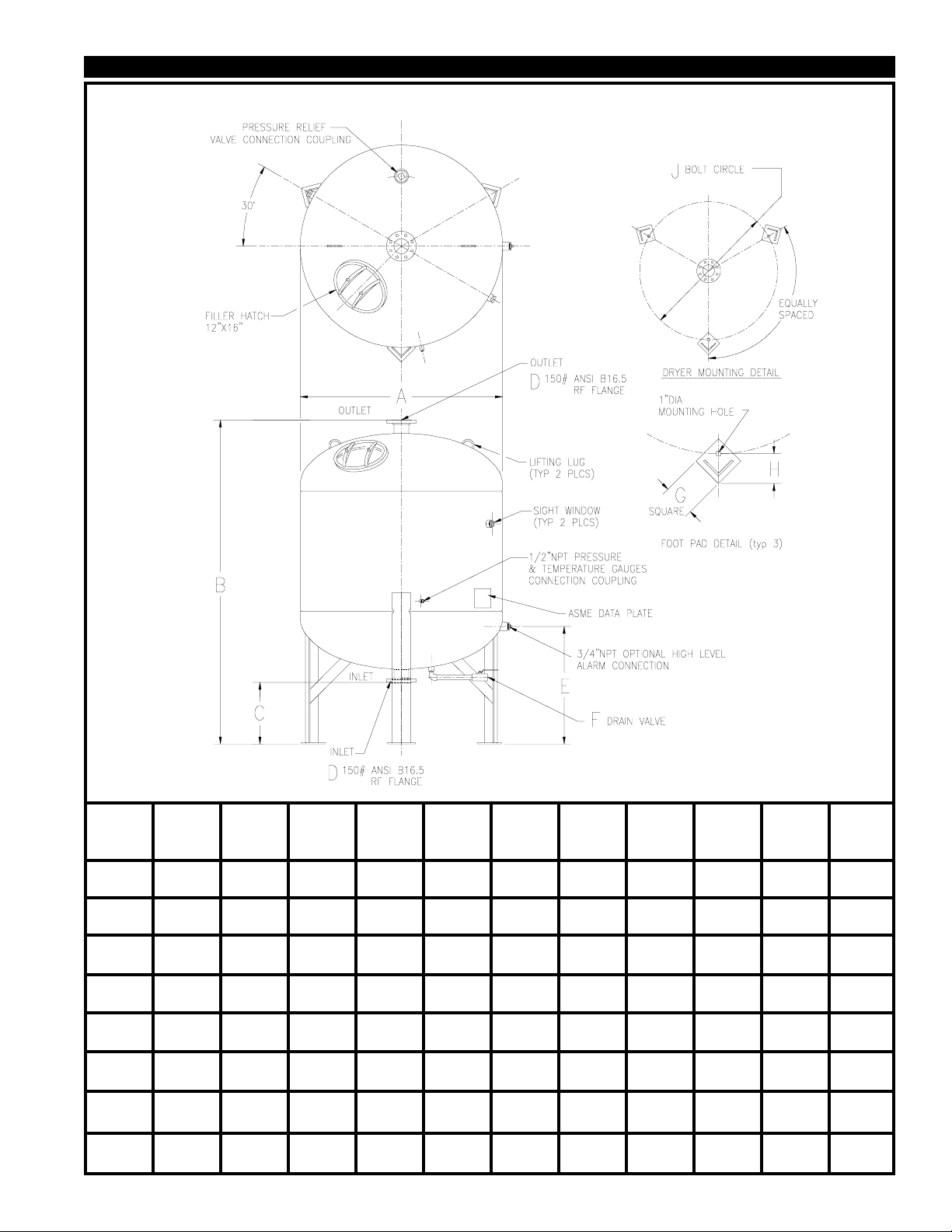
FIGURE 4 DRYER DIMENSIONAL DETAILS
MODEL
NO.
D-42
D-48
D-54
D-60
D-66
D-72
D-78
D-84
APPROX
WEIGHT
w/o Desiccant
1275 LBS
2150 LBS
2640 LBS
2700 LBS
3200 LBS
4075 LBS
4775 LBS
5700 LBS
A
42-3/4"
1085.9mm
48-3/4"
1238.3mm
54-3/4"
1390.7mm
60-3/4"
1543.1mm
66-3/4"
1695.5mm
72-3/4"
1847.9mm
78-7/8"
2003.4mm
85"
2159mm
B
85-5/8"
2174.9mm
91-1/4"
2317.8mm
94-1/4"
2393.9mm
97-1/4"
2470.2mm
100-1/4"
2546.4mm
109-7/16"
2779.7mm
114-9/16"
2909.9mm
123-9/16"
3138.5mm
C
16"
406.4mm
18-1/2"
469.9mm
18-1/2"
469.9mm
18-1/2"
469.9mm
18-1/2"
469.9mm
18-7/16"
468.3mm
20-11/16"
525.5mm
20-11/16"
525.5mm
D
4" 150#
FLANGE
4" 150#
FLANGE
4" 150#
FLANGE
4" 150#
FLANGE
6" 150#
FLANGE
6" 150#
FLANGE
6" 150#
FLANGE
6" 150#
FLANGE
E
27-13/16"
706.4mm
31-7/8"
809.6mm
34-3/8"
873.1mm
35-5/16"
896.9mm
36-3/8"
923.9mm
36-15/16"
938.2mm
41-1/2"
1054.1mm
41-1/2"
1054.1mm
F
1" NPT
1" NPT
1" NPT
2" NPT
2" NPT
2" NPT
2" NPT
2" NPT
G
6"
152.4mm
6"
152.4mm
6"
152.4mm
6"
152.4mm
6"
152.4mm
8"
203.2mm
8"
203.2mm
8"
203.2mm
H
5-5/8"
142.9
5-5/8"
142.9mm
5-5/8"
142.9mm
5-5/8"
142.9mm
5-5/8"
142.9mm
7-1/16"
179.4mm
7-1/16"
179.4mm
7-1/16"
179.4mm
J
40"
1016mm
46"
1168.4mm
52"
1320.8mm
58"
1473.2mm
64"
1625.6mm
70"
1778mm
76"
1930mm
82"
2082.8mm
PAGE 5
Page 6

SECTION 3 OPERATION
3.1 START UP PROCEDURES
Close the inlet isolation valve and open the bypass valve.
Open the outlet isolation valve SLOWLY and allow some air to bleed
through the drain valve; then close the drain valve. When the dryer
reaches normal operating pressure, SLOWLY turn the inlet valve to
full open position; then close the bypass valve.
If the vessel was installed without the bypass or isolation valves,
SLOWLY pressurize the air system. Allow some air to bleed through
the drain valve. Once the vessel starts to pressurize, the drain valve
can be closed.
Close the bypass valve. The dryer is now on stream.
CAUTION
Make sure that the dryer is not subjected to sudden flow
surges. Always open the valves slowly to permit gradual
equalization of pressure between the dryer and the air
supply lines.
3.2 OPERATING THE DRYER
The simple design of the single tower dryer allows for easy
operation. The dryer requires two procedures to ensure peak
performance.
3.2-A DAILY DRAINING
The accumulated solution in the bottom of the dryer should be
drained at least once for every 8 hours of operation.
Depending upon actual operating conditions, the dryer may
require draining on a more frequent basis.
If an automatic ball valve type drain valve was installed on the
dryer, set the time cycle for every 4 to 8 hours. If a manual
drain valve was installed, it must be opened at least once every
4 to 8 hours to drain the dryer.
CAUTION
If the dryer is not drained regularly, it may become
flooded. Accumulated liquid may enter the air system and
cause damage to downstream equipment.
On a new installation, continue to drain all downstream traps for
several days (or until no water is evident) after dryer is installed.
This period is required to dry out any accumulated water in the
compressed air system. Once the water is removed, the downstream traps should not need to be drained again.
3.2-B REFILLING THE DRYER WITH DESICCANT
During the VAN AIR drying process, the desiccant tablets dissolve
slowly. More tablets must be added to the supply when the top of
the bed drops to the sight window level (minimum level). Reference
FIGURE 5.
The desiccant consumption rate depends on several factors, such
as inlet temperature, flow, pressure and the type of desiccant being
used . With average conditions, the desiccant will usually need to
be added only two to three times per year when the dryer is
operating one shift per day. However, until the actual usage rate
is determined, check the bed level monthly.
Reference Section 4.5 for estimated consumption rates and
refilling instructions.
IMPORTANT
Use VAN AIR desiccant only. Filling dryer with any
other material will void the warranty.
3.3 USING THE SIGHT WINDOWS
WARNING
IF THE SIGHT WINDOWS ARE DAMAGED IN ANY WAY,
REPLACE THEM IMMEDIATELY WITH VAN AIR
PART NO. 26-0104 only. REFERENCE SECTION 4.3.
To check the level of the desiccant bed, look into one of the sight
windows. When the top of the desiccant bed is level with the sight
windows, the desiccant supply has dropped to the minimum level.
The bed must be replenished to raise the bed level to the maximum
level.
SECTION 4 MAINTENANCE
4.1 DAILY PROCEDURES
After every 8 hour period of operation, drain accumulated solution
from the bottom of dryer. Open manual drain valve and allow the
solution to discharge from the dryer, then close the manual drain
valve securely.
4.2 MONTHLY PROCEDURES
Check the level of the desiccant bed by looking into the sight window.
If the top of the desiccant bed is level with the sight window, the
desiccant bed must be replenished.
Check the operation of all equipment installed before and after the
dryer.
Check the afterfilter element condition. If the pressure differential
across the filter is high (6 to 9 PSID), replace the element.
Inspect the hatch cover for signs of corrosion and/or leaks. Replace
the cover and/or gasket if necessary.
PAGE 6
4.3 REPLACING THE SIGHT WINDOWS (P/N 26-0104)
WARNING
DEPRESSURIZE DRYER COMPLETELY BEFORE
REMOVING THE SIGHT WINDOW.
Using a pipe wrench, unthread the old sight window. Remove
all pipe sealant, rust or dirt from the coupling.
Apply a layer of pipe sealant to the threads of the new sight
window. DO NOT USE TEFLON TAPE. Tape may prevent
the sight window from threading into the coupling far enough.
4.4 DESICCANT SUPPORT GRID
If the grid becomes damaged, it can be replaced. The grid consists
of plastic grid pipes and steel top rings.
Should the grid require replacment, detailed instructions for
replacement will be provided with the new grid.
Page 7
SECTION 4 MAINTENANCE
4.5 ADDITION OF DESICCANT
WARNING
DO NOT REMOVE, REPAIR, OR REPLACE ANY ITEM ON
THE DRYER WHILE IT IS UNDER PRESSURE.
DEPRESSURIZE THE DRYER COMPLETELY BEFORE
STARTING INSTALLATION AND/OR MAINTENANCE
PROCEDURES. SERIOUS PERSONAL INJURY MAY
RESULT IF THESE SAFETY RULES ARE NOT FOLLOWED.
DO NOT REMOVE THE HATCH COVER UNTIL ALL AIR
PRESSURE IS OUT OF THE VESSEL. PUSH ON THE
HATCH COVER BY HAND TO FIND OUT IF THE VESSEL
PRESSURE IS REDUCED TO ZERO.
DO NOT TRY TO TIGHTEN THE HATCH COVER IF YOU
HEAR OR FEEL A LEAK. IMMEDIATELY SHUT OFF THE
AIR OR GAS SUPPLY TO THE VESSEL AND REDUCE THE
DRYER PRESSURE TO ZERO.
ALWAYS INSTALL A NEW GASKET EVERY TIME THE
HATCH COVER IS REMOVED, OR AT LEAST ONCE PER
YEAR. REPLACE THE HATCH COVER EVERY FIVE
YEARS REGARDLESS OF CONDITION. USE VAN AIR
AUTHORIZED PARTS ONLY.
DO NOT USE POWER TOOLS OR CHEATER BARS TO
TIGHTEN THE NUT ON THE COVER. TOO MUCH FORCE
CAN DISTORT THE COVER AND/OR THE GASKET. IF
DAMAGED BY OVERTIGHTENING, THE COVER CAN
BLOW OUT AND CAUSE SERIOUS INJURY. (Note:
Tighten the nut until it is snug only. When pressure is in
the vessel, the seal will be complete.)
INSPECT THE COVER AND SEALING SURFACE EVERY
TIME THE COVER IS REMOVED, OR AT LEAST ONCE A
YEAR, FOR DAMAGE SUCH AS CORROSION, CRACKS,
OR DISTORTION. IF THERE IS ANY DAMAGE, INSTALL A
NEW COVER AND GASKET. USE VAN AIR AUTHORIZED
PARTS ONLY.
Open the bypass valve. Close the dryer inlet and outlet isolation
valves. If the bypass and inlet and outlet isolation valves were not
installed, shut down the air system.
Open the drain valve and allow the dryer to depressurize completely.
Loosen the wing nut on the hatch cover. Do not remove the nut, or
the cover will fall into the vessel.
Push on the hatch cover. If the vessel is depressurized, the cover will
unseal. Once the seal is broken, slide the handle so that it is parallel
with the centerline of the long side of the opening. Tilt the hatch cover
and remove it from the dryer.
Add the amount of desiccant tablets required to raise the supply to
the normal operating level or to maximum level (see FIGURE 5); then
level off the tablet bed.
CAUTION
Make sure that the desiccant does not cover the screen
on the outlet pipe.
Check the sealing surface of the opening. If it is contaminated with
dirt or rust, it must be cleaned before installing the hatch cover. A
contaminated surface may prevent the gasket from properly sealing.
Install the filler hatch cover and gasket. Finger tighten the wing nut
on the hatch cover. Overtightening will cause damage to the nut. The
cover will seal when the vessel is pressurized.
Start the dryer following the start up procedures in Section 3.1
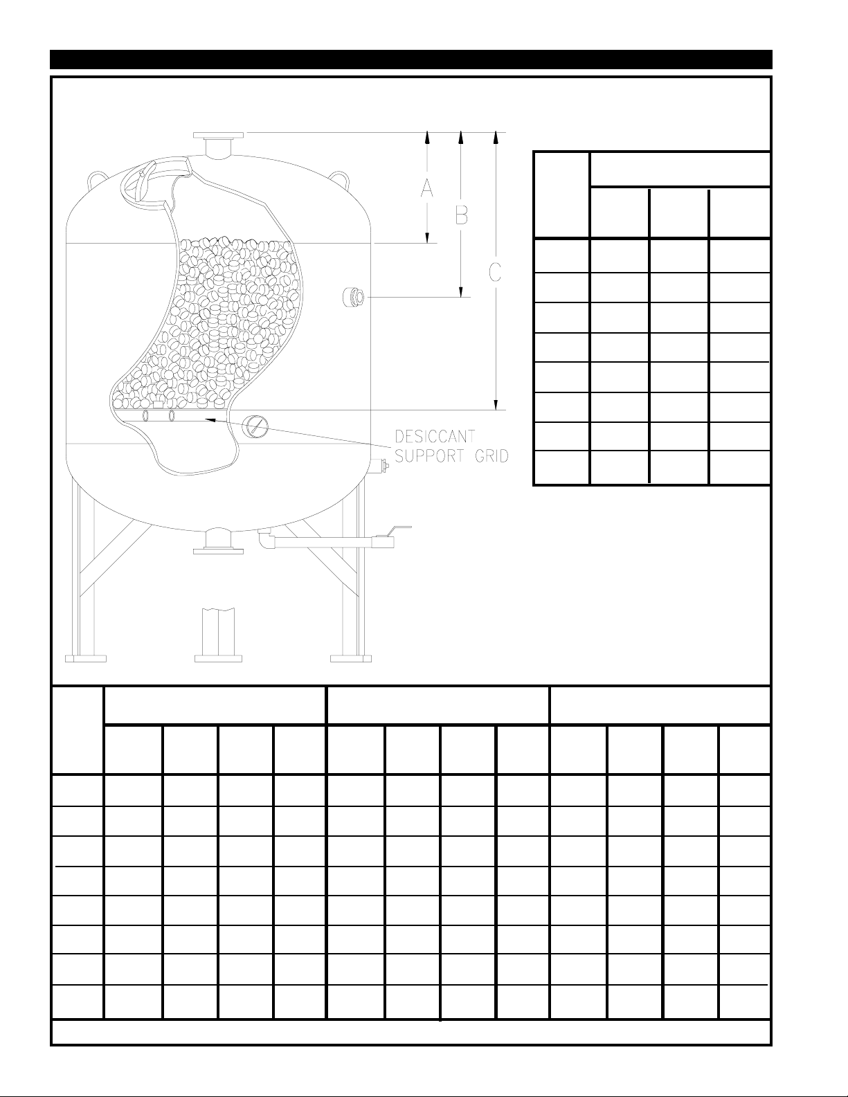
4.5-A BED LEVEL GUIDE
To determine the supply of desiccant in the dryer, insert a
measuring stick through the filler hatch until it reaches the top
of the desiccant bed; dimensions in FIGURE 5 are calculated
from the filler hatch to levels indicated on the drawing. (NOTE:
Dimensions are approximate and are intended as a general
guide only.)
4.5-B DESICCANT USAGE GUIDE
The chemical and physical characteristics of Van Air desiccant
contribute to its effectiveness and economy.
The DESICCANT CONSUMPTION RATE should be used as a
guide to estimate the usage of desiccant your installation will
require. The formula is based on an annual usage rate of one shift
per day, 5 days per week and 50 weeks per year or 2,000
operating hours per year. The figure is an average and may vary
depending upon your actual conditions (i.e. 24 hour operation,
higher inlet temperature, excessive liquid water content and/or
contaminants.)
DESICCANT CONSUMPTION
(Based upon 1 shift for a one year period @ 100 psig inlet pressure
and 75oF inlet temperature, 100% RH.)
FLOW
SCFM
100
1,000
10,000
To use the chart, first determine the SCFM that is being
processed through the dryer. Locate the nearest flow rate listed
on the chart and interpolate as necessary.
The consumption rate is proportional to the moisture loading.
Each 20oF change in inlet temperature changes the moisture
loading by a factor of nearly 2:1.
The quantity shown in the consumption rate chart is NOT the
quantity that must be added to the dryer at one time. The bed
level should be maintained at least to the minimum level at all
times to ensure optimum drying capabilities. The consumption
rate is an approximation of how much desiccant will be
added over a period of one year.
DRY-O-LITE
LBS/YEAR
132
1,320
13,200
SP
LBS/YEAR
665
6,650
66,500
10 BF
LBS/YEAR
576
5,760
57,600
Do NOT overfill the vessel. Adequate space must be left
to allow the hatch cover to be installed.
Check the condition of the hatch covet. If is damaged, it must be
replaced. The gasket should be replaced every time.
PAGE 7
Page 8
SECTION 4 MAINTENANCE
FIGURE 5 BED LEVEL DETAIL
BED DIMENSIONS
INCHES (centimeters)
MODEL
D-42
D-48
D-54
D-60
D-66
D-72
D-78
D-84
A
MAX.
Level
16-13/16
42.7
18-3/8
46.7
19-7/8
50.5
21-3/8
54.3
22-7/8
58.1
24-1/2
62.2
25-15/16
65.9
27-7/16
69.7
B
MIN.
Level
26-9/16
67.5
28-1/8
71.4
29-5/8
75.2
31-1/8
79.1
32-5/8
82.9
40-1/4
102.2
41-11/16
105.9
43-3/16
109.7
C
Total
Depth
44-9/16
113.2
46-1/8
117.2
47-5/8
121.0
49-1/8
124.8
50-5/8
128.6
58-1/4
148.0
59-11/16
151.6
61-3/16
155.4
DRY-O-LITE QUANTITY*
POUNDS (kilograms)
MIN to
Lbs./In
MODEL
D-42
of bed**
60.75
27.6
D-48
78.75
35.7
D-54
99.75
45.3
D-60
123.0
55.8
D-66
148.5
67.4
D-72
177
80.3
D-78
207
93.9
D-84
241.5
109.5
* Amounts are pounds (kilograms) required to fill dryer to levels indicated. ** Amounts in italics are kilograms per centimeter of bed depth.
PAGE 8
MIN.
Level
1094
496
1418
643
1796
815
2214
1004
2673
1212
3186
1445
3726
1690
4347
1972
MAX
Level
1686
765
2186
991
2769
1256
3413
1548
4121
1869
5974
2710
6986
3169
8151
3697
MAX
Level
592
269
768
348
973
441
1199
544
1448
657
2788
1265
3260
1479
3804
1725
SP or HPD QUANTITY*
POUNDS (kilograms)
Lbs./In
of bed**
44.6
20.2
57.75
26.2
73.2
33.2
90.2
40.9
108.9
49.4
129.8
58.9
151.8
68.9
177.1
80.33
MIN.
Level
803
364
1040
472
1318
598
1624
737
1960
889
2336
1060
2732
1239
3188
1446
MAX
Level
1238
562
1603
727
2032
922
2503
1136
3022
1371
4380
1987
5123
2324
5977
2711
MIN to
MAX
Level
435
197
563
255
714
324
879
399
1062
482
2044
927
2391
1085
2789
1265
10 BF QUANTITY*
POUNDS (kilograms)
Lbs./In
of bed**
52.7
23.9
68.3
31.0
86.5
39.2
106.6
48.4
128.7
58.4
153.4
69.6
179.4
81.4
209.3
94.9
MIN.
Level
949
430
1229
557
1557
706
1919
870
2317
1051
2761
1252
3229
1465
3767
1709
MAX
Level
1463
663
1895
859
2400
1088
2958
1341
3572
1620
5177
2348
6055
2747
7063
3204
MIN to
MAX
Level
514
233
666
302
843
382
1039
471
1255
569
2416
1096
2826
1282
3296
1495
Page 9

SECTION 5 TROUBLESHOOTING
1. DECREASED PERFORMANCE - High desiccant usage.
High inlet air temperatures.
Check the aftercooler performance. Make sure that the
aftercooler was properly sized and installed. Check the aftercooler
operation manual for further details.
If an aftercooler was not installed, one may be required.
Check the compressor capacity or air usage vs. the dryer rating.
3. DECREASED PERFORMANCE - low desiccant usage.
The desiccant bed may be contaminated.
The dryer will tolerate normal amounts of compressor lubricant. If
the compressor manufacturer's recommended lubrication rate is
exceeded, the desiccant bed can become contaminated with
compressor lubricants.
Periodically check the desiccant bed. If the tablets are discolored
(deep yellow or brown), the bed may be contaminated.
Was a different compressor installed?
High ambient temperatures.
Check the location of the dryer for changes in ambient temperatures.
Was the dryer moved to a different location?
Was a piece of equipment or piping installed near the dryer that
caused an increase in ambient temperatures? Relocate the dryer
or equipment if possible. If relocation is not possible, correct the
ambient temperature.
Dryer overloaded.
Check the flow through the dryer. Check the flow at peak usage
periods. Have the flow requirements of the system increased?
Was the dryer properly sized for the actual operating conditions?
Check the capacity of the dryer for the system conditions. If the
system requirements exceed the dryer's capability, a larger dryer
must be installed.
Desiccant bed below required level.
Check the desiccant bed level. The level should be checked at
least once a month. The usage of desiccant will vary with the
operating conditions and the type of desicccant being used. The
dryer will require more desiccant during the warmer months of the
year.
Desiccant quantities and filling procedures are outlined in Section
4.4 of this manual.
If the bed has become contaminated, it can be flushed with an
adequate supply of water. Depending upon the severity of
contamination, it might be necessary to completely flush the entire
bed from the dryer and replace it with new desiccant.
Check the compressor for proper operation. The compressor
might be worn or over lubricated. Check the compressor
operator's manual and correct.
Check the atmospheric air near the compressor air intake. Heavy
concentrations of acid fumes or smoke and dust will cause
contamination if they are drawn into the air system. Check or
install a filter on the compressor intake.
If it is not possible to reduce the amount of lubricants in the air
system, a separator and/or coalescing filter should be installed
before the dryer.
2. LIQUID DOWNSTREAM OF THE DRYER.
Improper draining. The dryer may be flooded.
The dryer must be drained at least once for every 8 hours of
operation.
Check the drain valve(s) and piping for clogs. Repair or replace
faulty valves. If the piping is clogged, it must be cleared.
If the dryer is installed outdoors where ambient temperatures fall
below freezing, the drain line and valve(s) may freeze. If ambient
temperatures fall below freezing, the drain line can be wrapped
with heat tracing and/or insulation to prevent freezing.
If maintaining the required draining schedule is a problem, an
automatic ball type drain valve should be installed. Reference
Section 2.2-F in this manual for installation instructions.
IMPORTANT: Never install a float type or solenoid type drain valve
on this dryer.
Bypass valve open or faulty.
Check the dryer bypass valve. It might be faulty or open allowing
untreated air to enter the air system.
Low or no desiccant in the dryer.
Check the dryer deissiccant bed level. Reference Section 4.4 for
filling quantities and procedures.
If the above check list does not remedy the problem, consult your local VAN AIR distributor or call
the VAN AIR factory in Lake City, Pennsylvania PHONE (814) 774-2631 or FAX (814) 774-3482.
PAGE 9
Page 10
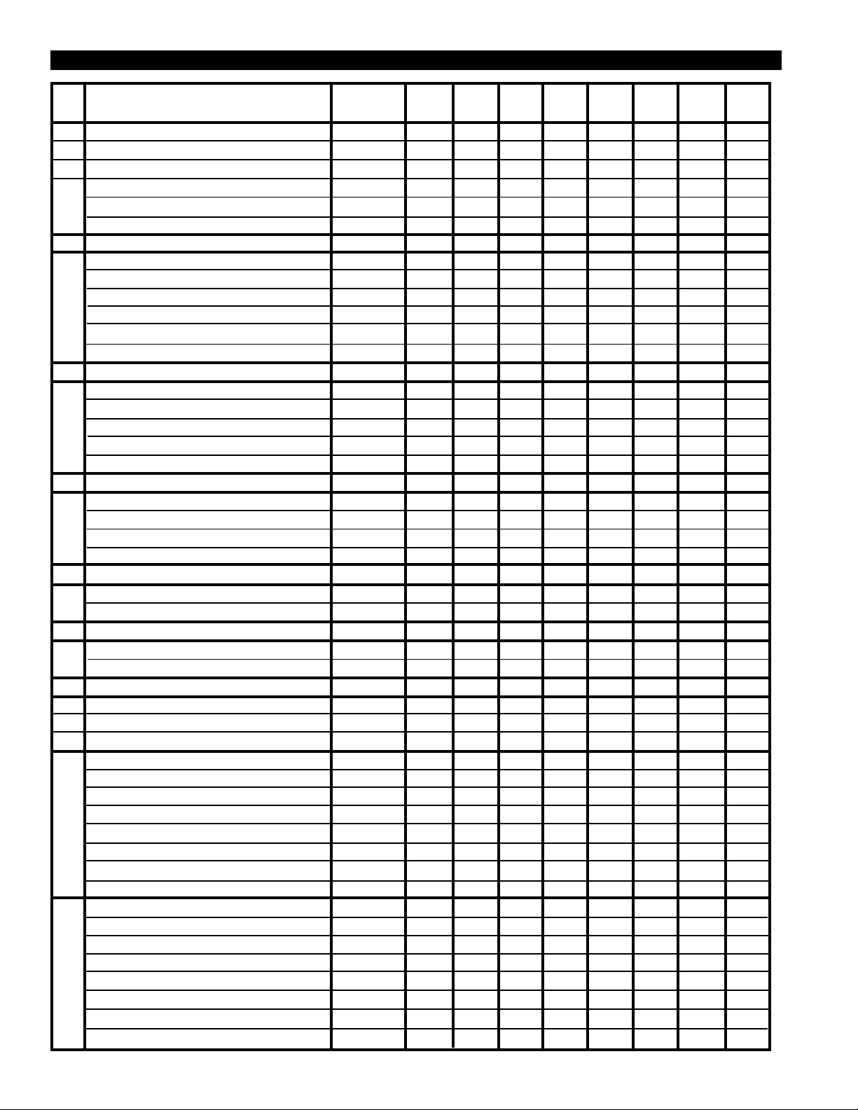
SECTION 6 REPLACEMENT PARTS
ITEM
Gasket for 12" x 16" hatch cover
1
Hatch Cover, 12" x 16"
2
Sight Window
3
Manual Drain Valve 1" NPT
4
Manual Drain Valve 2" NPT
5
DRY-O-LITE Desiccant, 55 LB BAG
DRY-O-LITE Desiccant, 506 LB DRUM
SP Desiccant, 50 LB BAG
10BF Desiccant, 25 LB PAIL
OPTIONAL PRESSURE RELIEF VALVES
6
1-1/2" NPT 150# set pressure
2" NPT 150# set pressure
2" NPT 125# set pressure
2-1/2" NPT 125# set pressure
2" NPT 125# set pressure
7
Pressure gauge kit
Temperature gauge kit
Combination pressure and temperature
DESCRIPTION
DESICCANT
OPTIONAL GAUGE KITS
PART NO.
18-0347
46-2147
26-0104
29-0451
29-0542
33-0159
33-0203
33-0205
33-0232
14-0540
14-0990
14-1664
14-1665
14-1663
29-0252
29-0326
29-0200
D42
QTY
1
1
2
1
--
31
4
34
68
1
--
--
--
--
1
1
1
D48
QTY
1
1
2
1
--
42
5
46
92
1
--
--
--
--
1
1
1
D54
QTY
1
1
2
1
--
53
6
58
116
-1
--
--
--
1
1
1
D60
QTY
1
1
2
-1
66
8
72
144
--
--
--
-1
1
1
1
D66
QTY
1
1
2
-1
80
9
88
176
--
--
--
-1
1
1
1
D72
QTY
1
1
2
-1
115
13
126
252
--
-1
--
--
1
1
1
D78
QTY
1
1
2
-1
135
15
148
296
--
--
-1
--
1
1
1
D84
QTY
1
1
2
-1
182
20
200
400
--
--
-1
--
1
1
1
8
9
10
a
b
c
d
e
OPTIONAL HIGH LEVEL ALARM
HLA-120 High level alarm kit
OPTIONAL AUTOMATIC DRAIN VALVE
MDV-400I
REPLACEMENT GRID PARTS
BOLT
NUT
WASHER
D-42 TOP RING SECTION
D-48 TOP RING SECTION
D-54 TOP RING SECTION
D-60 TOP RING SECTION
D-66 TOP RING SECTION
D-72 TOP RING SECTION
D-78 TOP RING SECTION
D-84 TOP RING SECTION
D-42 GRID TUBES
D-48 GRID TUBES
D-54 GRID TUBES
D-60 GRID TUBES
D-66 GRID TUBES
D-72 GRID TUBES
D-78 GRID TUBES
D-84 GRID TUBES
26-3667
39-2411121
28-0105
28-0104
28-0301
46-1505
46-1506
46-1507
46-1508
46-1509
46-1510
Call Factory
Call Factory
17-0502
17-0504
17-0506
17-0508
17-0512
17-0510
17-0520
17-0518
1
1
4
4
4
4
--
--
--
--
--
--
-1
--
--
--
--
--
--
--
1
1
4
4
4
-4
--
--
--
--
--
--
-1
--
--
--
--
--
--
1
1
4
4
4
--
-4
--
--
--
--
--
--
-1
--
--
--
--
--
1
1
5
5
5
--
--
-5
--
--
--
--
--
--
-1
--
--
--
--
1
1
6
6
6
--
--
--
-6
--
--
--
--
--
--
-1
--
--
--
1
1
6
6
6
--
--
--
--
-6
--
--
--
--
--
--
-1
--
--
1
1
7
7
7
--
--
--
--
--
--
CALL
--
--
--
--
--
--
-1
--
1
1
7
7
7
--
--
--
--
--
--
--
CALL
--
--
--
--
--
--
-1
PAGE 10
Page 11
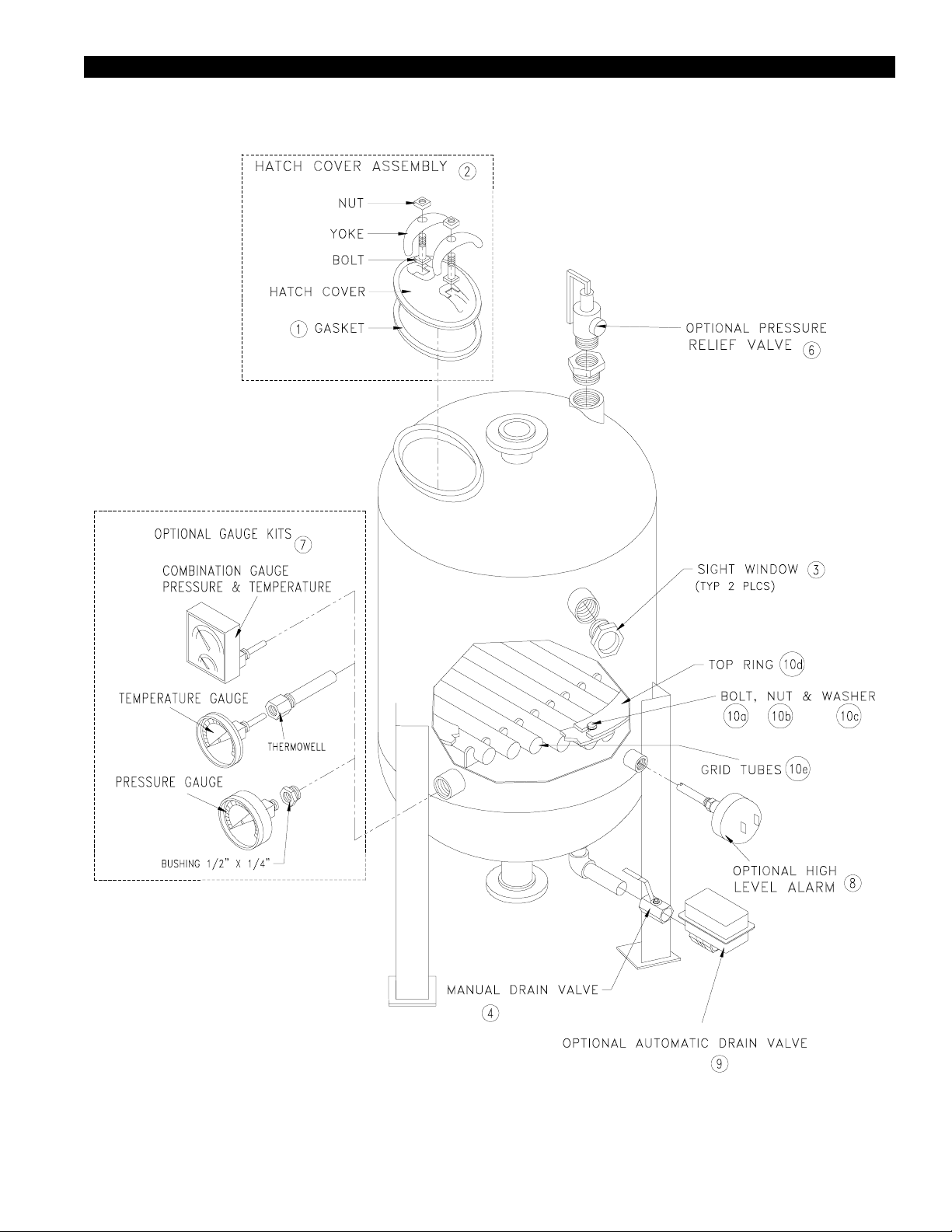
SECTION 6 REPLACEMENT PARTS
PAGE 11
Page 12
YOUR VAN AIR REPRESENTATIVE IS:
NAME:
COMPANY:
ADDRESS
CITY: STATE: ZIP
PHONE: FAX:
ATTACH BUSINESS CARD HERE
MAKING COMPRESSED AIR AND GAS WORK BETTER SINCE 1944.
PAGE 12
2950 Mechanic Street
Lake City, PA 16423-2095
Phone: 814/774-2631
Fax: 814/774-3482
 Loading...