

Page 1
P/N: 432-00128
INST ALLA TION INSTRUCTIONS
®
E101/102 SERIES FILTER ELEMENTS
(FOR F101, F102 AND FHP SERIES FILTER HOUSING - ALL GRADES)
APRIL 2000
GRADE
AA
A
B
C
To reduce energy consumption from excessive pressure drop and minimize chance of contaminant carryover, install new elements
before pressure drop reaches 10 psid (except grade RD). Install new RD elements when hydrocarbon vapors are first detected
downstream or every six months, whichever comes first.
DESCRIPTION
Extra Coarse Coalescing
Coarse Coalescing
General Purpose Coalescing
High Efficiency Coalescing
ENDCAP COLOR
Black
Green
Red
Blue
GRADE
RAA
RA
RB
RC
HT
RD
DESCRIPTION
Extra Coarse Particulate
Coarse Particulate
General Purpose Particulate
High Efficiency Particulate
High Temperature Particulate
Vapor Adsorbing
ENDCAP COLOR
Black
Green
Red
Blue
Zinc Plate
Black
WARNINGS
BEFORE INSTALLING NEW ELEMENT(S), READ INSTRUCTION MANUAL CAREFULLY. NOTE SERIES OF FILTER HOUSING
(F101, F102 OR FHP) AND CONSULT THE APPROPRIATE SECTION FOR SPECIFIC INSTRUCTIONS.
F101 SERIES
Close inlet and outlet shut-off valves (and open by-pass valve
1.
if provided); or lock out compressed air supply to filter housing.
WARNING
DO NOT LOOSEN FLANGE BOLTS BEFORE THE
VESSEL IS COMPLETELY DEPRESSURIZED.
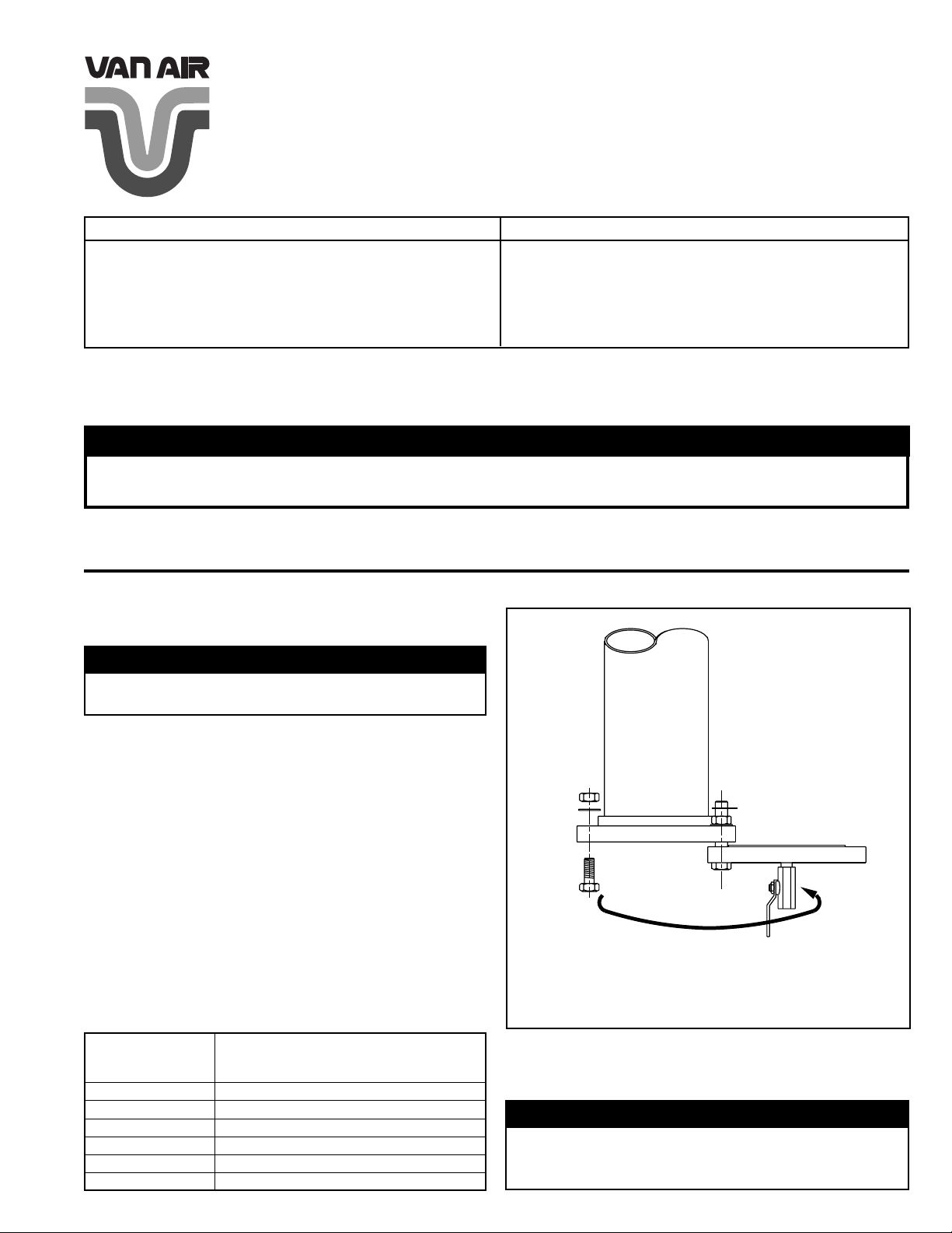
FIGURE 1 LONG FLANGE BOLT (F101-500 thru 2000)
On units with manual drain valve, stand clear and turn manual
2.
valve until fully open. Leave valve open until all pressure is out
of filter housing and bottom blind flange is removed. On units
with automatic drain valves (timed electric type) allow valve to
cycle until all pressure is out of filter housing.
Provide support under blind flange to prevent it from falling
3.
when bolts are removed.
Remove bolts from flange and lower blind flange for access to
4.
elements.
5.
Remove hex fastener from tie rod and remove used element
from housing. Discard used element properly.
NOTE
Filter models F101-500 thru F101-2000 are equipped
TABLE 1 BOTTOM BLIND FLANGE WEIGHTS
(F101 Series)
BOTTOM
FILTER
MODEL
F101-500
F101-1000
F101-1500
F101-2000
F101-3500
F101-5000
PRINTED IN THE USA © 2000 VAN AIR SYSTEMS INC. 2950 MECHANIC STREET, LAKE CITY, PA 16423 PAGE 1
BLIND FLANGE WEIGHT
(LBS.)
28
47
69
69
102
177
with a single long flange bolt to permit rotating of blind
flange for access to elements.
WARNING
BLIND FLANGES ARE HEAVY AND COULD CAUSE INJURY IF ALLOWED TO FALL. SEE (TABLE 1) FOR BLIND
FLANGE WEIGHTS.
Page 2
6.
Remove new element from packaging. Remove small plastic
bag (o-ring inside)and rubber band from element. Install new
small o-ring in groove on hex fastener. Be sure that large o-ring
is firmly and squarely positioned on top end cap.
7.
Install element in housing so that the tie rod protrudes through
the small hole in the bottom endcap.
8.
Thread hex fastener onto the tie rod and tighten so that
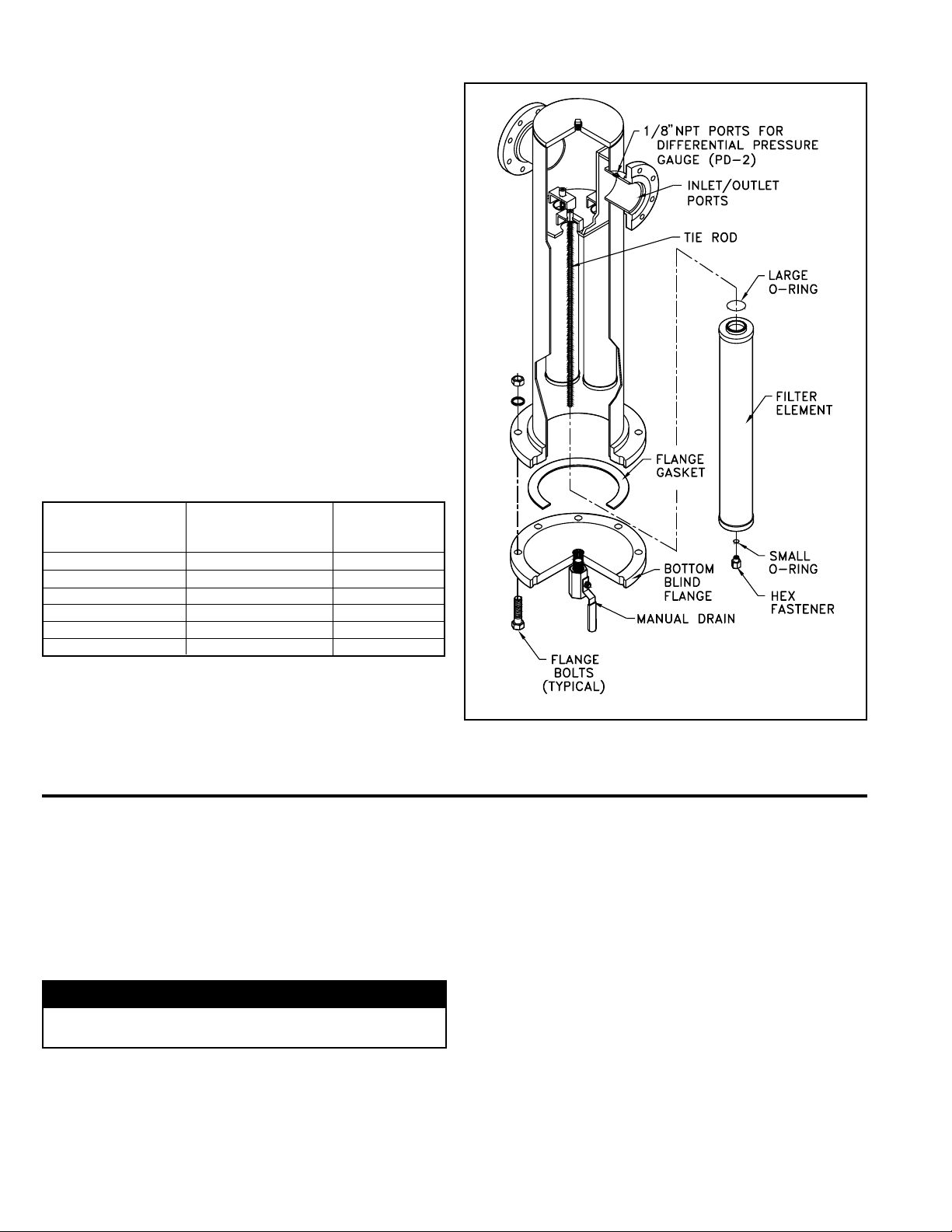
element is held firmly in place. Do not overtighten. (See Figure
2).
9.
Repeat same procedure for each new element required. (See
Table 2 for Element Replacement Data).
10.
Before closing housing, inspect the interior to make certain all
of the new elements have been installed.
11.
With gasket in place, carefully raise blind flange and align bolt
holes. Insert all bolts and completely tighten all nuts evenly.
Close drain valve; then slowly open inlet and outlet valves.
12.
Close by-pass valve if provided. Check for leaks.
13.
Filter is now in service.
TABLE 2 ELEMENT REPLACEMENT DATA
(F101 Series)
REPLACEMENT
FILTER
MODEL
F101-500-(*)
F101-1000-(*)
F101-1500-(*)
F101-2000-(*)
F101-3500-(*)
F101-5000-(*)
*Insert appropriate filtration grades here; for example F101-3500-C uses
replacement element E101/102-625-C (five required).
ELEMENT
MODEL NUMBER
E101/102-500-(*)
E101/102-500-(*)
E101/102-500-(*)
E101/102-625-(*)
E101/102-625-(*)
E101/102-625-(*)
NUMBER OF
ELEMENTS IN
HOUSING
1
2
3
3
5
8
FIGURE 2 TYPICAL ASSEMBLY (F101 Series)
F102 SERIES
Close inlet and outlet shutoff valves (and open by-pass valve
1.
if provided); or lock out all compressed air supply to filter
housing.
2.
On units with manual drain valves stand clear and turn both
manual drain valves until fully open. Leave valves open until
all pressure is out of filter housing and T-bolt/swing bolt closure
is open. On units with automatic drain valves (timed electric
type) allow valve to cycle until all pressure is out of filter
housing.
WARNING
DO NOT LOOSEN SWING BOLTS BEFORE THE VESSEL
IS COMPLETELY DEPRESSURIZED.
Loosen swing bolt nuts until they will clear the tabs on the
3.
enclosure. It is not necessary to remove the nuts from the
bolts. (See Figure 3).
4.
Remove hex fasteners from tie rods and lift used elements
from housing. Discard used elements properly.
5.
Remove new element from packaging. Remove small plastic
bag (o-ring inside)and rubber band from element. Install new
PAGE 2 © 2000 VAN AIR SYSTEMS INC. 2950 MECHANIC STREET, LAKE CITY, PA 16423 PRINTED IN THE USA
small o-ring in groove on hex fastener. Be sure that large oring is firmly and squarely positioned on the end cap with the
large opening.
Install element in housing so that the tie rod protrudes through
6.
the small hole in endcap. End cap with large opening faces
down.
7.
Thread hex fastener onto the tie rod and tighten so that
element is held firmly in place. Do not overtighten (See Figure
3).
8.
Repeat same procedure for each new element required. (See
Table 3 for Element Replacement Data).
Before closing housing, inspect baffle to make certain all the
9.
new elements have been installed.
10.
With enclosure o-rings in place, carefully lower enclosure and
raise all swing bolts over tabs. Tighten all nuts evenly.
11.
Close drain valve; then slowly open inlet and outlet valves.
Close by-pass valve if provided. Check for leaks.
12.
Filter is now in service.
Page 3
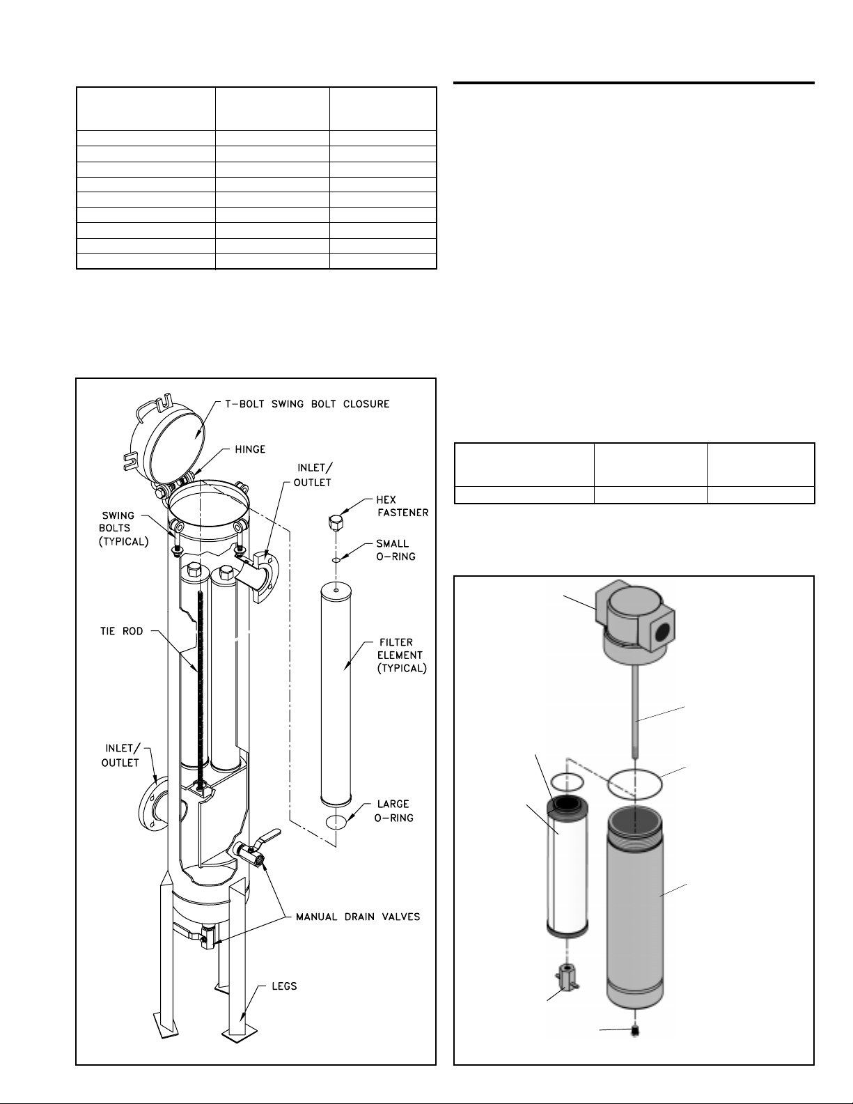
TABLE 3 ELEMENT REPLACEMENT DATA
(F102 Series)
FILTER
MODEL
F102-1500-(*)
F102-2000-(*)
F102-3500-(*)
F102-5000-(*)
F102-7500-(*)
F102-10,000-(*)
F102-12,500-(*)
F102-15,000-(*)
F102-20,000-(*)
*Insert appropriate filtration grades here; for example F102-3500-C uses
replacement element E101/102-625-C (five required).
REPLACEMENT
ELEMENT
MODEL NUMBER
E101/102-500-(*)
E101/102-625-(*)
E101/102-625-(*)
E101/102-625-(*)
E101/102-625-(*)
E101/102-625-(*)
E101/102-625-(*)
E101/102-625-(*)
E101/102-625-(*)
NUMBER OF
ELEMENTS IN
HOUSING
3
3
5
8
12
16
20
24
32
FIGURE 3 TYPICAL ASSEMBLY (F102 Series)
FHP-670-7.25
Close inlet and outlet shutoff valves (and open by-pass valve
1.
if provided); or lock out all compressed air supply to filter
housing.
2.
Completely depressurize filter before removing filter bowl.
Remove filter bowl using a spanner or strap wrench, turning
3.
bowl counterclockwise.
Remove locknut from bottom of element and pull element down
4.
off of seat. (See Figure 4).
5.
Lightly grease element o-ring and slide element onto tie rod.
Thread the lock nut onto the tie rod and tighten hand tight.
Ensure body o-ring is seated inside filter head. Lightly grease
6.
filter bowl threads and thread it into filter head. Tighten with a
spanner or strap wrench.
Tighten the drain plug then slowly open inlet and outlet shutoff
7.
valves. Close bypass valve (if provided).
Filter is now in service.
8.
FILTER
MODEL
FHP-670-7.25-(*)
*Insert appropriate filtration grades here; for example FHP-670-7.25-C
uses replacement element E101/102-500-C (one required).
REPLACEMENT
ELEMENT
MODEL NUMBER
E101/102-500-(*)
NUMBER OF
ELEMENTS IN
HOUSING
1
FIGURE 4 TYPICAL ASSEMBLY (FHP-670-7.25)
FILTER HEAD
TIE ROD
ELEMENT
O-RING
FILTER
ELEMENT
BODY O-RING
FILTER BOWL
LOCKNUT
1/4" NPT
DRAIN PLUG
PRINTED IN THE USA © 2000 VAN AIR SYSTEMS INC. 2950 MECHANIC STREET, LAKE CITY, PA 16423 PAGE 3
Page 4
WARRANTY
I. INSTALLATION.
Unless otherwise set forth in a quotation and/or acknowledgment, Seller shall not be responsible
for installation. Cost of and all risks of damage to the equipment and/or components thereof
caused by installation shall be the sole responsibility of Buyer. If supervision of installation and/
or supervision of start up of the equipment is to be provided by Seller, Buyer shall assume all costs
incurred by Seller in furnishing supervision. If supervision of installation and/or supervision of start
up of the equipment is provided by Seller, Seller shall only be responsible for any loss or damage
growing out of a direct negligent act or acts of Seller’s supervisor.
SELLER SHALL NOT BE RESPONSIBLE FOR IMPROPER OPERATION OF THE EQUIPMENT
DUE TO FAULTY ERECTION OR INSTALLATION.
II. PERFORMANCE.
Seller shall have no responsibility for the performance of its Goods when installed under
conditions varying materially from those under which the product is usually tested or operated
under existing industry standards.
III. WARRANTY
All filter housings manufactured by Seller are guaranteed to be free of defective materials and
workmanship for a period of five (5) years from the date of shipment. This warranty does not include
elements, drain line components, gaskets, o-rings or any other types of seals, or any accessories
All goods manufactured by Seller are guaranteed to be free from defective materials and
workmanship for a period of one (1) year from date of shipment. The equipment and accessories
sold but not manufactured by Seller are guaranteed only to the extent that either Seller or Buyer
is able to recover under the manufacturer's warranty. This warranty shall not be assignable to
buyer.
or expendable items.
The above warranties for all products described do not cover abuse, neglect, lack of normal
maintenance, accidents or other exceptional circumstances.
Date of shipment will be defined as the date of departure from the factory or from distributor stock.
A copy of the distributor invoice to the customer at time of shipment is required as verification of
shipment from distributor stock. Equipment start up will be verified by receipt of the product
registration card.
Seller’s obligation under this warranty may, at its option, be discharged by furnishing or repairing,
without charge, FOB its factory, a similar part to replace any part of its own manufacture which
within the above specified periods, proves to have been defective, provided that within a
reasonable time for inspection after delivery, Seller is notified of such defects and the equipment,
material or part claimed to be defective is delivered pre-paid to Seller at Lake City, Pennsylvania
with evidence that it has been properly maintained and used in accordance with instructions. If,
in connection with such warranties, repairs are performed by the Buyer with the written
authorization of Seller, then the expense in connection with such repairs shall not exceed the cost
of material and direct labor. If such repairs are performed by Buyer without the written
authorization of Seller, Seller will not assume any of the expenses in connection with such repairs
and will immediately void any remaining warranty on the Goods.
THE REPAIR OR REPLACEMENT WARRANTY HEREIN SET FORTH IS THE EXCLUSIVE
WARRANTY GIVEN BY SELLER FOR ITS GOODS. THIS WARRANTY IS GIVEN IN LIEU OF
ANY OR ALL WARRANTIES, WHETHER WRITTEN OR ORAL, EXPRESSED OR IMPLIED.
ANY AND ALL IMPLIED WARRANTIES OF MERCHANTABILITY OR FITNESS FOR ANY
PARTICULAR PURPOSE ARE HEREBY EXPRESSLY EXCLUDED BY SELLER. SELLER
NEITHER ASSUMES, NOR DOES IT AUTHORIZE ANY OTHER PERSON TO ASSUME ON ITS
BEHALF ANY OTHER LIABILITY IN CONNECTION WITH THE SALE OF ITS GOODS.
IV. LIMITATIONS OF LIABILITIES AND INDEMNITIES.
IN NO CASE, WHETHER AS A RESULT OF BREACH OF CONTRACT, BREACH OF WARRANTY
OR TORT (INCLUDING SELLER’S OR BUYER’S NEGLIGENCE OR STRICT LIABILITY) SHALL
SELLER BE LIABLE FOR ANY CONSEQUENTIAL OR INCIDENTAL DAMAGES INCURRED BY
BUYER, INCLUDING, BUT NOT LIMITED TO, LOSS OF SALES PROFIT, REVENUE, OR GOOD
WILL; LOSS OF USE OF GOODS OR ANY ASSOCIATED EQUIPMENT OR MATERIAL; COST OF
CAPITAL; COST OF SUBSTITUTE PRODUCTS, FACILITIES OR SERVICES; DOWN TIME COSTS;
ATTORNEY’S FEES; OR LOSSES OR CLAIMS OF CUSTOMERS OF BUYER FOR SUCH
DAMAGES BUYER HEREBY AGREES TO INDEMNIFY AND HOLD HARMLESS SELLER FROM
ANY AND ALL SUCH DAMAGES. BUYER FURTHER AGREES TO DEFEND, INDEMNIFY AND
HOLD HARMLESS SELLER FROM ANY AND ALL CLAIMS, LIABILITY, DAMAGES OR EXPENSES
(INCLUDING ATTORNEY’S FEES) DUE TO PERSONAL INJURIES OR DEATH, TO BUYER, ITS
EMPLOYEES, AND THIRD PARTIES AND FROM PROPERTY DAMAGE RESULTING FROM THE
NEGLIGENCE OR STRICT LIABILITY OF BUYER NOT WITHSTANDING THE PROVISIONS OF
ANY WORKER COMPENSATION OR SIMILAR STATUTE.
V. SERVICE, OPERATING PROCEDURE, WARNINGS.
Should Buyer request start up supervision by Seller, a maximum number of days required for this
supervision may be included and specified in the quotation and/or acknowledgment as a separate
price item. The specified days are only approximate, since start up supervision is contingent upon
equipment and work supplied by others and beyond the control of Seller, and Seller shall be paid for
any days actually worked in addition to those specified on a pro-rata basis.
Start up supervision and warranty supervision and warranty service time will include all elapsed time
during the standard working hours, as defined by Seller, or Seller’s representative from the time
Seller’s representative leaves his operating base or another customer’s plant.
Where the service to be performed is start up supervision. Seller should be notified approximately
30 days prior to start up Seller’s representatives may be required to have standard time verification
sheets approved by Buyer’s authorized representative, and the name and title of this representative
should be furnished to Seller with the notification.
Unless set forth in the quotation and/or acknowledgment, Seller shall not be obligated to provide
special operating manuals or operating procedures for the operation of its equipment or supply special
warning placards to be affixed to the equipment. If such manuals, procedures or placards are provided
by Seller, Buyer shall be responsible for payment of cost of furnishing such items, for instructing any
operator of the equipment as to the contents of such manuals and/or procedures; for requiring that
such procedures be abided by; for insuring that warning placards remain affixed to the equipment and
for requiring operators to abide by warning placards.
Any safety equipment required to be worn by any operator or maintenance person shall be provided
by Buyer, and the failure to provide such equipment or the failure to require the use thereof shall be
the Buyer’s sole responsibility. Buyer shall indemnify and hold Seller harmless for any liability with
respect thereto.
Seller shall not be responsible for providing safety devices and/or guarding of the equipment except
as provided for in the quotation and/or acknowledgment, and Buyer specifically assumes all
responsibility for supplying such safety devices and/or guarding necessary for the safe operation of
the equipment. If safety devices and/or guarding are specified in the quotation and/or acknowledgment,
Buyer shall be solely responsible for making certain that any operator of the equipment uses such
safety devices and/or guarding and Buyer shall indemnify and hold Seller harmless with respect to
any property damage and/or personal injury, including death, occasioned by any person by reason
of such failure on the part of Buyer and/or its operator.
2950 Mechanic Street
Lake City, PA 16423-2095
Phone: 814/774-2631
MAKING COMPRESSED AIR AND GAS WORK BETTER SINCE 1944.
Fax: 814/774-3482
PAGE 4 © 2000 VAN AIR SYSTEMS INC. 2950 MECHANIC STREET, LAKE CITY, PA 16423 PRINTED IN THE USA
 Loading...