

Page 1
April 2012
P/N 432-10016-D
INSTALLATION, OPERATION & MAINTENANCE INSTRUCTION
F200 SERIES
COMPRESSED AIR FILTERS
PRODUCT PURPOSE & FUNCTION:
Van Air's F200 series lters are designed to remove contaminants from compressed air systems. Available in 1/4" to 3"
connection sizes and ow capacities from 15 to 1250 SCFM (at 100 psig) in 15 housings and 9 ltration grades, the F200 series
can remove oil aerosols, oil vapors, water and particulates. Housings are made of cast aluminum and coated with an epoxy powder
coating for corrosion resistance. All units include push-on elements with durable polyester drain layer (except RD grade).
Accessories include differential pressure indicators, wall mounting kits, connector kits, and automatic drain valves.
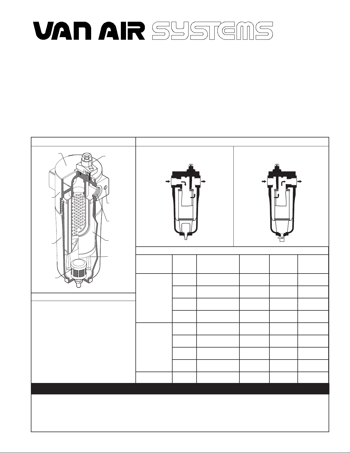
FILTER DETAILS
BLANKING
PLATE
FILTER
HEAD
FILTER
BOWL
ADM-2-2
(OPTIONAL)
OPERATING CONDITIONS
MAXIMUM WORKING PRESSURE
All Models
OPERATING TEMPERATURE
Minimum
Maximum
MAXIMUM RECOMMENDED INLET
TEMPERATURE
AA, A, RAA, RA, RB, and RC Series
B Series
C Series
RD Series
PD-6 POP-UP
INDICATOR
(STANDARD)
THRU-BOLT
HOLES
INLET/
OUTLET
ELEMENT
ELEMENT
SUPPORT
250 PSIG
35°F
225°F
225°F
175°F
125°F
80°F
FLOW DIRECTION THROUGH ELEMENT
(COALESCING)
IN/OUT
INLET
APPLICATION ELEMENT
OIL
REMOVAL
(LIQUIDS)
PARTICULATE
REMOVAL
(SOLIDS)
OIL VAPOR
REMOVAL
GRADE
AA
A
B
C
RAA
RA
RB
RC
RD
WARNINGS
OUTLET
INLET
FILTRATION GRADES
PURPOSE NOMINAL
Extra Coarse
Coalescing
Coarse
Coalescing
General Purpose
Coalescing
High Efciency
Coalescing
Extra Coarse
Particulate
Coarse
Particulate
General Purpose
Particulate
High Efciency
Particulate
Vapor Absorbing
PARTICULE
REMOVAL
25.00 μ IN/OUT WHITE
1.00 μ IN/OUT RED
25.00 μ OUT/IN WHITE
(PARTICULATE)
OUT/IN
OUTLET
ELEMENT
FLOW
DIRECTION
5.00 μ IN/OUT GREEN
0.01 μ IN/OUT BLUE
5.00 μ OUT/IN GREEN
1.00 μ OUT/IN RED
0.01 μ OUT/IN BLUE
0.01 μ OUT/IN WHITE
COLOR
CODE
DO NOT REPLACE ANY ITEM ON FILTER WHILE IT IS PRESSURIZED.
•
DO NOT OPERATE A LEAKING FILTER. TAKE FILTER OUT OF SERVICE IMMEDIATELY.
•
DO NOT OPERATE ABOVE MAXIMUM WORKING PRESSURE (MWP) AT MAXIMUM OPERATING TEMPERATURE (°F).
•
PAGE 1
Page 2
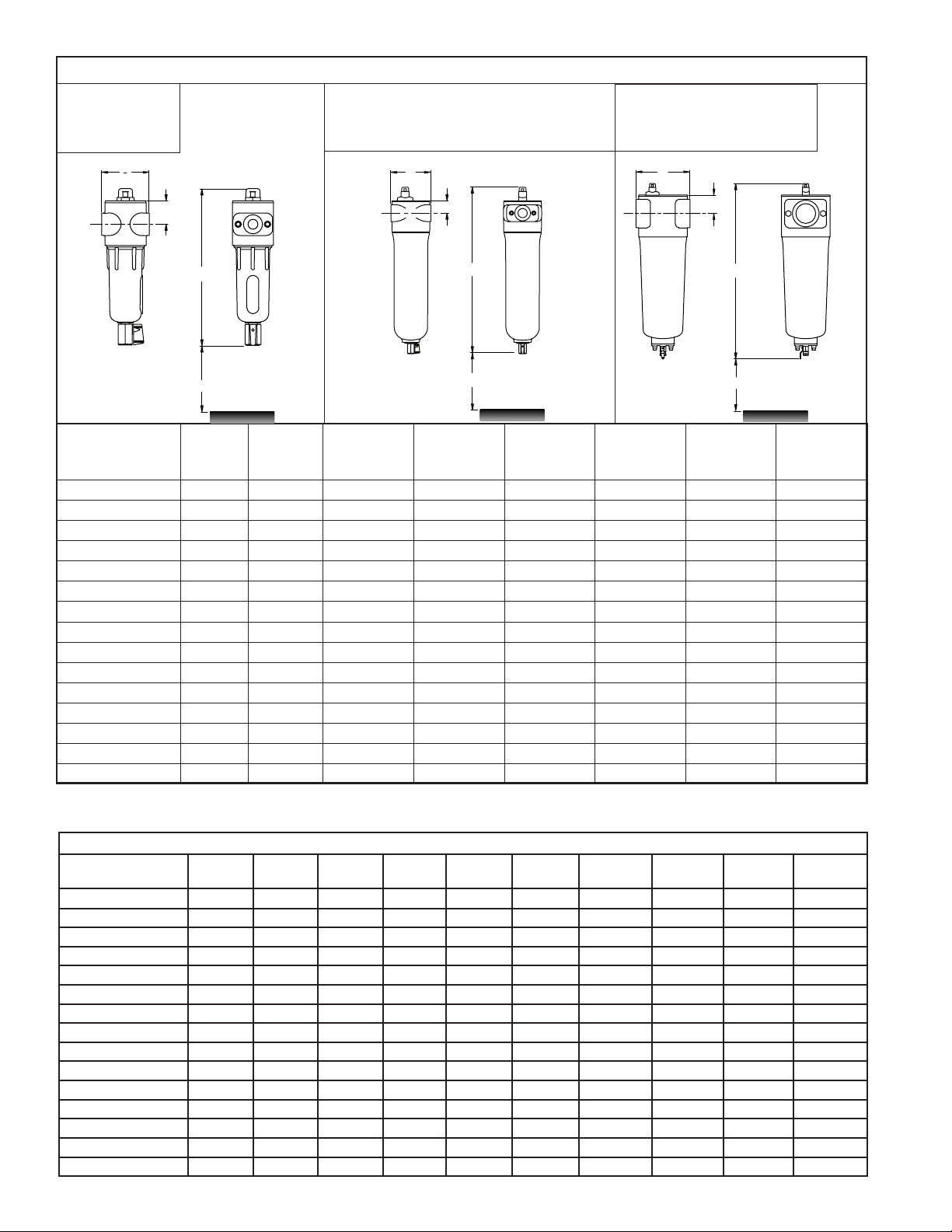
DIMENSIONS FOR:
F200-15-1/4
F200-25-3/8
F200-25-1/2
FILTER HOUSING DIMENSIONS & WEIGHTS
DIMENSIONS FOR:
F200-55-1/2
F200-85-3/4
F200-100-1
F200-150-1
F200-265-1-1/4
F200-350-1-1/2
F200-400-2
F200-500-2
DIMENSIONS FOR:
F200-600-3 F200-1250-3
F200-800-3
F200-1000-3
A
FILTER MODEL
B
C
ELEMENT
REMOVAL
D
CLEARANCE
FLOW**
(SCFM)
IN/OUT
CONN.
(NPT)
A
(INCHES)
A
B
C
D
B
(INCHES)
ELEMENT
REMOVAL
CLEARANCE
(INCHES)
C***
D
(INCHES)
A
B
C
ELEMENT
D
REMOVAL
CLEARANCE
HOUSING
WEIGHT****
(LBS)
ELEMENT
WEIGHT****
(LBS)
F200-15-1/4-(*) 15 1/4" 2-13/16 1-5/8 9-1/4 3 1.3 0.1
F200-25-3/8-(*) 25 3/8" 2-13/16 1-5/8 9-1/4 3 1.3 0.1
F200-25-1/2-(*) 25 1/2" 2-13/16 1-5/8 9-1/4 3 1.3 0.1
F200-55-1/2-(*) 55 1/2" 3-7/16 1-5/16 11-3/4 4 3.2 0.3
F200-85-3/4-(*) 85 3/4" 4-15/16 1-5/8 14-9/16 4 5.7 0.5
F200-100-1-(*) 100 1" 4-15/16 1-5/8 14-9/16 4 5.7 0.6
F200-150-1-(*) 150 1" 4-15/16 1-5/8 20-7/16 6 6.7 0.9
F200-265-1-1/4-(*) 265 1-1/4" 4-15/16 1-5/8 20-7/16 6 6.7 1
F200-350-1-1/2-(*) 350 1-1/2" 5-5/16 2-1/16 21-3/8 6 8.7 1.1
F200-400-2-(*) 400 2" 5-5/16 2-1/16 21-3/8 6 8.7 1.1
F200-500-2-(*) 500 2" 5-5/16 2-1/16 29-3/8 6 9.9 2.3
F200-600-3-(*) 600 3" 7-7/8 2-3/4 24-1/2 8 19.8 2.7
F200-800-3-(*) 800 3" 7-7/8 2-3/4 30-1/16 8 21.9 3.6
F200-1000-3-(*) 1000 3" 7-7/8 2-3/4 34-3/4 12 28.1 4.3
F200-1250-3-(*) 1250 3" 7-7/8 2-3/4 34-3/4 12 28.1 4.3
*Insert appropriate ltration grades here; for example F200-15-1/4-B.
***Dimensions include lter housing, PD-6 and manual drain.
**Flow is based on SCFM @ 100 PSIG @ 100°F.
****For total lter weight, add element weight to housing weight.
FLOW CAPACITIES AT VARIOUS OPERATING PRESSURES (SCFM)
FILTER MODEL 25
PSIG
50
PSIG
75
PSIG
100
PSIG
125
PSIG
150
PSIG
175
PSIG
200
PSIG
225
PSIG
F200-15-1/4 8 11 13 15 17 18 20 21 23 24
F200-25-3/8 13 18 22 25 28 31 33 35 38 40
F200-25-1/2 13 18 22 25 28 31 33 35 38 40
F200-55-1/2 28 39 48 55 62 67 73 78 83 87
F200-85-3/4 43 60 74 85 95 104 112 120 128 134
F200-100-1 50 71 87 100 11 2 122 132 141 150 158
F200-150-1 75 107 131 150 168 183 198 212 225 237
F200-265-1-1/4 133 188 231 265 297 323 350 374 398 419
F200-350-1-1/2 175 249 305 350 392 427 462 494 525 553
F200-400-2 200 284 348 400 448 488 528 564 600 632
F200-500-2 250 355 435 500 560 610 660 705 750 790
F200-600-3 300 426 522 600 672 732 792 846 900 948
F200-800-3 400 568 696 800 896 976 1056 1128 1200 1264
F200-1000-3 500 710 870 1000 1120 1220 1320 1410 1500 1508
F200-1250-3 625 888 1088 1250 1400 1525 1650 1763 1875 1885
PAGE 2
250
PSIG
Page 3
INSTALLATION
Before installing lter, check operating temperature and pres-
1.
sure conditions to verify that they are within the specied
ranges. (See Operating Conditions on page 1). Also verify
that system ow rate corresponds to the rated capacity of
the lter. Operating at ows above rated capacity will result
in increased pressure drop.
Locate Filter at the point of lowest operating temperature to
2.
ensure that water and oil vapor do not condense downstream
of the lter. Filter should be installed close to the point of
use to minimize the risk of pipe scale, dirt, etc. recontaminating the compressed air. This is particularly important when
installing a new lter on an existing system that has not had
proper ltration.
Install lter vertically. Provide required minimum clearance
3.
below lter to allow for replacement of element.
(See Element Removal Clearance on page 2).
Protect lter from reverse ow conditions. Do not install lter
4.
downstream of quick opening valves.
Remove lter head from the bowl by turning bowl counter-
5.
clockwise. Pull element from locator. Set bowl and element
aside for use later.
Install inlet and outlet shutoff valves to facilitate replacement
6.
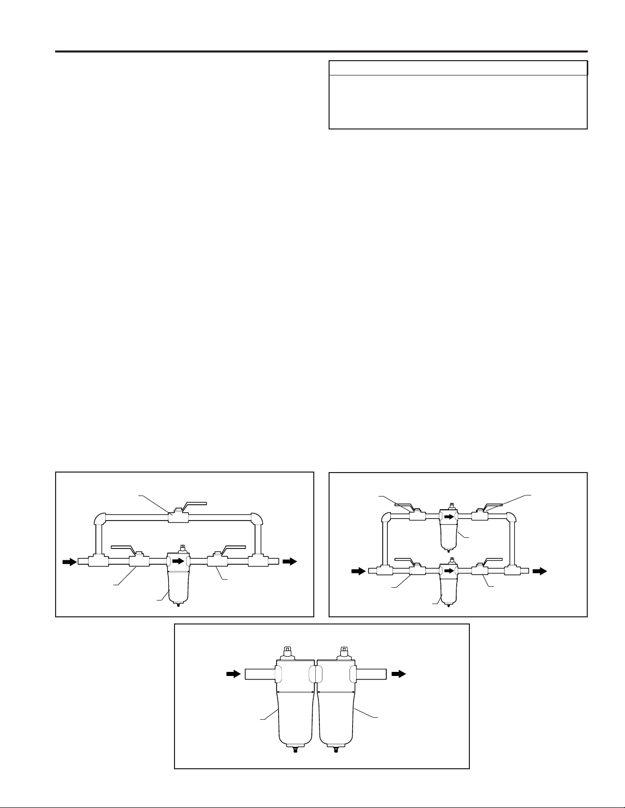
of element. Bypass piping is recommended (See Figure 1A
and 1B). MAKE SURE VALVES ARE CLOSED BEFORE
PROCEEDING.
IMPORTANT
INSTALL FILTER HEAD INTO THE PIPING WITH ARROWS POINTING IN THE PROPER DIRECTION TO
ENSURE PROPER OPERATION. (SEE FLOW DIRECTION DIAGRAM BELOW).
8.
Install element by pushing onto element locator on lter head.
Check to make sure that the o-ring in the head is in the proper
9.
position. Thread lter bowl into lter head and tighten either
by hand (models F200-15 through 55) or with strap wrench
(models F200-85 through 1250). Do not over tighten. Overtightening could damage lter bowl or make it difcult to remove.
10.
Make sure drain valve on bottom of lter is closed. On lters
equipped with ADM2-2 auto drain, provide a drain line to
remove accumulated water and oil.
11.
Pressurize system and slowly open inlet and outlet shutoff
valves.
12.
Check piping for leaks. Depressurize system and repair leaks
as needed.
13.
Re-pressurize system and slowly open inlet and outlet shutoff
valves. Close bypass valve if provided.
14.
Filter is now in service.
Connect lter head into piping. Avoid reducers or bushings to
7.
match inlet size. The resulting restriction will increase pressure
drop. Make sure head is installed with ow arrows pointing
in proper direction. Use pipe thread compound as required.
FIGURE 1A BYPASS
BYPASS
VALV E
INLET
SHUTOFF
VALV E
FILTER
OUTLET
SHUTOFF
VALV E
FIGURE 1C FILTERS MANIFOLDED WITH CONNECTOR KIT
FIGURE 1B FILTERED BYPASS
INLET
BYPASS
VALV E
INLET
SHUTOFF
VALV E
FILTER
OUTLET
BYPASS
VALV E
BYPASS
FILTER
OUTLET
SHUTOFF
VALV E
PARTICULATE
FILTER
(LOWER EF-
FICIENCY)
PAGE 3
COALESCING FILTER
(HIGHER EFFICIENCY)
Page 4
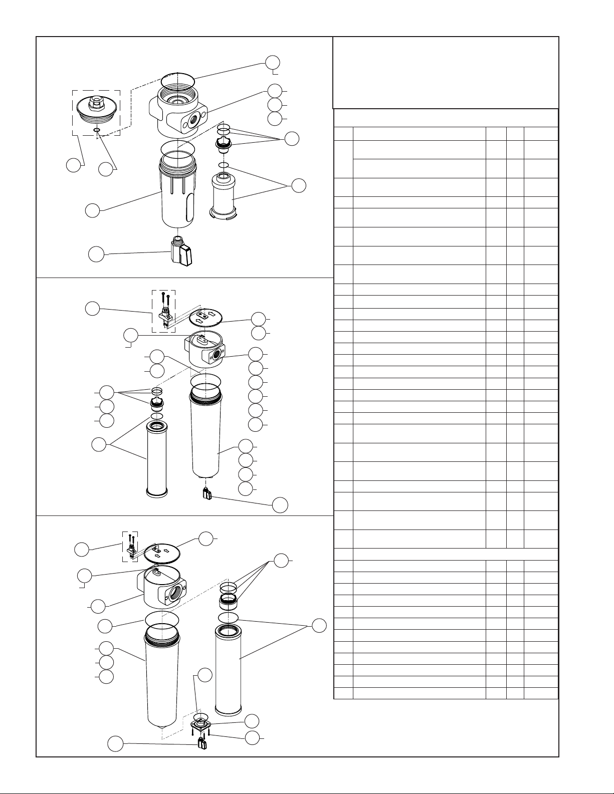
FIGURE 2A F200-15-1/4 THRU 25-1/2 REPLACEMENT PARTS
4A
2 PLACES
F200-15-1/4
5A
F200-25-3/8
5B
F200-25-1/2
5C
6A
1A
3A
8A
12
FIGURE 2B F200-55-1/2 THRU 500-2 REPLACEMENT PARTS
1B
F200-55-1/2
2A
F200-85-3/4
2B
THRU 500-2
F200-55-1/2
5D
F200-85-3/4
5E
F200-100-1 & 150-1
5F
F200-265-1-1/4
5G
F200-350-1-1/2
5H
F200-400-2 & 500-2
5J
F200-55-1/2
8B
F200-85-3/4 & 100-1
8C
F200-150-1 THRU 400-2
8D
F200-500-2
8E
F200-85-3/4 THRU 500-2
F200-55-1/2
F200-85-3/4 THRU
265-1-1/4
F200-350-1-1/2
THRU 500-2
2 PLACES
F200-55-1/2
6B
6C
6D
7
3B
4B
4C
12
FIGURE 2C F200-600-3 THRU 1250-3 REPLACEMENT PARTS
F200-600-3
2C
9
THRU 1250-3
6E
F200-600-3
THRU 1250-3
1B
2 PLACES
F200-600-3
THRU 1250-3
F200-600-3
F200-800-3
F200-1000-3
& 1250-3
3B
5K
4D
8F
8G
8H
Find the gure that references your lter.
1.
Find the replacement part you need and the item number of that
2.
part.
Find the item number in the rst column of the Replacement Parts
3.
table.
Find the part description that best describes the part.
4.
See the last column for the part number.
5.
REPLACEMENT PARTS
ITEM PART DESCRIPTION FIG 2- QTY PART NO.
Finding a part number
PD-6A-C DIFFERENTIAL PRESSURE
INDICATOR KIT FOR COALESCING FILTERS
1A
PD-6A-P DIFFERENTIAL PRESSURE
INDICATOR KIT FOR PARTICULATE FILTERS
7
1B PD-6 DIFFERENTIAL PRESSURE INDICA-
TOR KIT
2A BLANKING PLATE FOR F200-55-1/2 B 1 326-00110
2B BLANKING PLATE FOR F200-85-3/4 THRU
500-2
2C BLANKING PLATE FOR F200-600-3 THRU
1250-3
3A BLANKING PLATE O-RING FOR F200-15-1/4
THRU 25-1/2
3B BLANKING PLATE O-RING FOR F200-55-1/2
THRU 1250-3
4A BODY O-RING FOR F200-15-1/4 THRU 25-1/2 A 2 475-01000
4B BODY O-RING FOR F200-55-1/2 B 1 475-00146
4C BODY O-RING FOR F200-85-3/4 THRU 500-2 B 1 475-00242
4D BODY O-RING FOR F200-600-3 THRU 1250-3 C 1 475-00362
5A 1/4" NPT FILTER HEAD FOR F200-15-1/4 A 1 201-00100
5B 3/8" NPT FILTER HEAD FOR F200-25-3/8 A 1 201-00110
5C 1/2" NPT FILTER HEAD FOR F200-25-1/2 A 1 201-00120
5D 1/2" NPT FILTER HEAD FOR F200-55-1/2 B 1 201-00130
5E 3/4" NPT FILTER HEAD FOR F200-85-3/4 B 1 201-00140
5F 1" NPT FILTER HEAD FOR F200-100-1 & 150-1 B 1 201-00150
5G 1-1/4" NPT FILTER HEAD FOR F200-265-1-1/4 B 1 201-00160
5H 1-1/2" NPT FILTER HEAD FOR F200-350-1-1/2 B 1 201-00170
5J 2" NPT FILTER HEAD FOR F200-400-2 &
F200-500-2
5K 3" NPT FILTER HEAD FOR F200-600-3 THRU
1250-3
6A EPL1 ELEMENT ADAPTOR FOR F200-15-1/4
THRU 25-1/2
6B EPL2 ELEMENT ADAPTOR FOR F200-55-1/2 B 1 326-00010
6C EPL3 ELEMENT ADAPTOR F200-85-3/4 THRU
265-1-1/4
6D EPL4 ELEMENT ADAPTOR FOR F200-350-1-
1/2 THRU 500-2
6E EPL5 ELEMENT ADAPTOR FOR F200-600-3
THRU 1250-3
7 REPLACEMENT ELEMENTS (REFER TO PAGE 5)
8A FILTER BOWL FOR F200-15-1/4 THRU 25-1/2 A 1 201-01000
8B FILTER BOWL FOR F200-55-1/2 B 1 201-01010
8C FILTER BOWL FOR F200-85-3/4 & 100-1 B 1 201-01020
8D FILTER BOWL FOR F200-150-1 THRU 400-2 B 1 201-01030
8E FILTER BOWL FOR F200-500-2 B 1 201-01040
8F FILTER BOWL FOR F200-600-3 C 1 201-01050
7
8G FILTER BOWL FOR F200-800-3 C 1 201-01060
8H FILTER BOWL FOR F200-1000-3 & 1250-3 C 1 201-01070
9 DRAIN ADAPTOR O-RING C 1 475-00142
10 DRAIN ADAPTOR PLATE C 1 261-00006
11 DRAIN ADAPTOR SCREW C 4 460-00100
12 MANUAL DRAIN 1/4" KIT A,B, C 1 84-10852
A 1 84-10126
A 1 84-10127
B,C 1 84-10125
B 1 326-00120
B 1 326-00130
A 1 475-00110
B,C 2 475-00006
B 1 201-00180
C 1 201-00200
A 1 326-00005
B 1 326-00015
B 1 326-00020
C 1 326-00025
PAGE 4
10
4 PLACES
12
11
Page 5
REPLACEMENT ELEMENTS
FILTER MODEL ELEMENT MODEL PART NO. FILTER MODEL ELEMENT MODEL PART NO.
F200-15-1/4,
F200-25-3/8,
& F200-25-1/2
F200-55-1/2 E200-55-AA 26-10032 F200-500-2 E200-500-AA 26-10418
F200-85-3/4 E200-85-AA 26-10034 F200-600-3 E200-600-AA 26-10427
F200-100-1 E200-100-AA 26-10035 F200-800-3 E200-800-AA 26-10436
F200-150-1 E200-150-AA 26-10036 F200-1000-3 E200-1000-AA 26-10040
F200-265-1-1/4 E200-265-AA 26-10037 F200-1250-3 E200-1250-AA 26-7510
E200-15/25-AA 26-10400 F200-350-1-1/2,
E200-15/25-RAA 26-10401 E200-350/400-RAA 26-10410
E200-15/25-A 26-10402 E200-350/400-A 26-10411
E200-15/25-RA 26-10403 E200-350/400-RA 26-10412
E200-15/25-B 26-10404 E200-350/400-B 26-10413
E200-15/25-RB 26-10405 E200-350/400-RB 26-10414
E200-15/25-C 26-10406 E200-350/400-C 26-10415
E200-15/25-RC 26-10407 E200-350/400-RC 26-10416
E200-15/25-RD 26-10408 E200-350/400-RD 26-10417
E200-55-RAA 26-10107 E200-500-RAA 26-10419
E200-55-A 26-2059 E200-500-A 26-10420
E200-55-RA 26-2092 E200-500-RA 26-10421
E200-55-B 26-2070 E200-500-B 26-10422
E200-55-RB 26-2103 E200-500-RB 26-10423
E200-55-C 26-2081 E200-500-C 26-10424
E200-55-RC 26-2114 E200-500-RC 26-10425
E200-55-RD 26-2151 E200-500-RD 26-10426
E200-85-RAA 26-10109 E200-600-RAA 26-10428
E200-85-A 26-2061 E200-600-A 26-10429
E200-85-RA 26-2094 E200-600-RA 26-10430
E200-85-B 26-2072 E200-600-B 26-10431
E200-85-RB 26-2105 E200-600-RB 26-10432
E200-85-C 26-2083 E200-600-C 26-10433
E200-85-RC 26-2116 E200-600-RC 26-10434
E200-85-RD 26-2153 E200-600-RD 26-10435
E200-100-RAA 26-10110 E200-800-RAA 26-10437
E200-100-A 26-2062 E200-800-A 26-10438
E200-100-RA 26-2095 E200-800-RA 26-10439
E200-100-B 26-2073 E200-800-B 26-10440
E200-100-RB 26-2106 E200-800-RB 26-10441
E200-100-C 26-2084 E200-800-C 26-10442
E200-100-RC 26-2117 E200-800-RC 26-10443
E200-100-RD 26-2154 E200-800-RD 26-10444
E200-150-RAA 26-10111 E200-1000-RAA 26-10115
E200-150-A 26-2063 E200-1000-A 26-2067
E200-150-RA 26-2096 E200-1000-RA 26-2100
E200-150-B 26-2074 E200-1000-B 26-2078
E200-150-RB 26-2107 E200-1000-RB 26-2111
E200-150-C 26-2085 E200-1000-C 26-2089
E200-150-RC 26-2118 E200-1000-RC 26-2122
E200-150-RD 26-2155 E200-1000-RD 26-2159
E200-265-RAA 26-10112 E200-1250-RAA 26-7514
E200-265-A 26-2064 E200-1250-A 26-7509
E200-265-RA 26-2097 E200-1250-RA 26-7513
E200-265-B 26-2075 E200-1250-B 26-7511
E200-265-RB 26-2108 E200-1250-RB 26-7515
E200-265-C 26-2086 E200-1250-C 26-7512
E200-265-RC 26-2119 E200-1250-RC 26-7516
E200-265-RD 26-2156 E200-1250-RD 26-7517
& F200-400-2
E200-350/400-AA 26-10409
PAGE 5
Page 6
A
B
D
C
E
A
A
F
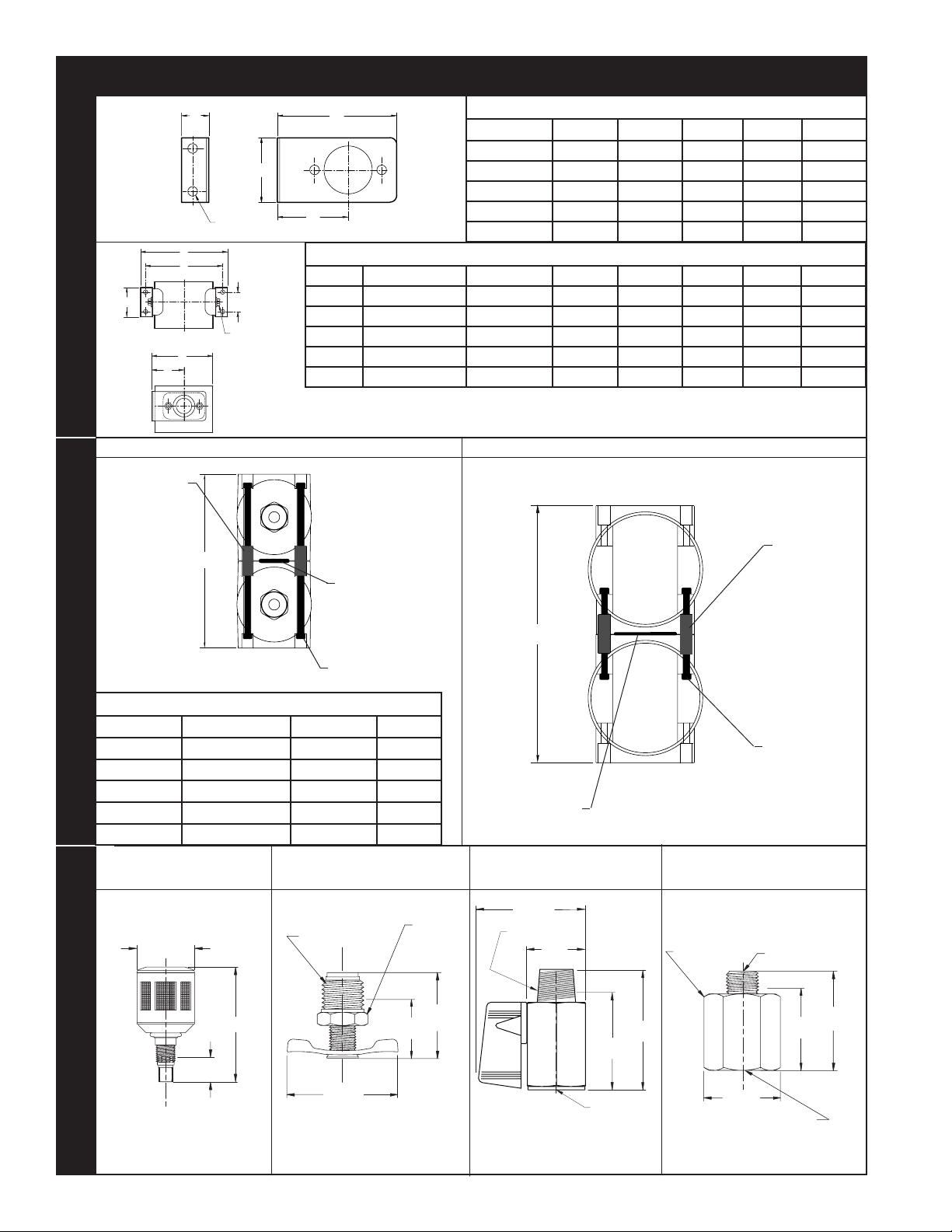
MOUNTING BRACKET KITSCONNECTOR KITSDRAIN KITS
STANDOFF
2 EACH
ACCESSORIES
MOUNTING BRACKET DIMENSIONS
TYPE A B C D E
MB-1 2-15/16" 1-9/16" 13/16" 1-3/4" 1/4"
MB-1-2 2-15/16" 1-9/16" 13/16" 1-3/4" 1/4"
MB-2 4-15/16" 2-3/8" 1" 2-9/16" 5/16"
MB-2-2 4-3/4" 2-3/4" 1" 2-3/4" 5/16"
MB-3-2 7-1/8" 4-15/16" 1-3/16" 3-15/16" 3/8"
E
A
B
TYPE USED ON PART NO A B C D E
MB-1 55 84-0720 4-1/2" 1-1/4" 1-3/4" 3-5/16" 5-1/4"
MB-1-2 15 THRU 25 84-10130 3-3/4" 1-1/4" 1-3/4" 3" 4-7/16"
HEX
D
C
NUT
(4 EACH)
MB-2 85 THRU 265 84-0721 5-15/16" 1-9/16" 2-9/16" 4-7/8" 6-11/16"
MB-2-2 350 THRU 500 84-10131 6-1/2" 2" 2-3/4" 5-1/4" 7-5/16"
MB-3-2 600 THRU 1250 84-10132 9-5/16" 3-3/4" 3-15/16" 7-7/16" 10-1/4"
CK-1 & CK-1-2
INSTALLED MOUNTING BRACKET KIT DIMENSIONS
KITS FOR MB-1 THRU MB-2-2 INCLUDES
(2) MOUNTING BRACKETS, (2) TIE RODS,
(2) WASHERS, & (2) NUTS.
NOTE: BLANKING PLATES REMOVED FOR CLARITY.
CK-2, CK-2-2 & CK-3-2
KIT FOR MB-3-2 INCLUDES (2) MOUNTING
BRACKETS, (4) SCREWS, (4) WASHERS, &
(4) NUTS.
O-RING
SCREW
4 EACH
CONNECTOR KIT DETAIL
TYPE USED ON PART NO A
CK-1 55 84-0723 7"
CK-1-2 15 THRU 25 84-10133 5-3/4"
CK-2 85 THRU 265 84-0724 9-7/8"
CK-2-2 350 THRU 500 84-10134 10-11/16"
CK-3-2 600 THRU 1250 84-10135 15-3/4"
ADM-2-2 AUTODRAIN
(P/N: 84-10852)
1-1/2"
1/4" BALL VALVE MANUAL
DRAIN (P/N: 84-10852)
1/4" N
PT
9/16"
WR
SI
ZE
O-RING
1/4" BALL VALVE MANUAL
DRAIN (P/N: 84-10852)
1-9/16"
EN
CH
1/4" MNPT
7/8"
STANDOFF
2 EACH
SCREW
4 EACH
1/4" TO 1/2" DRAIN ADAPTER
(P/N: 84-10851)
1-1/16"
WREN
CH
S
IZE
1/4" M
ALE NPT
PAGE 6
3"
*
11/16"
KIT INCLUDES (1) AUTO DRAIN, (1)
NUT, (1) O-RING & INSTRUCTION
SHEET.
* DIMENSION EXTENDING OUT OF
FILTER HOUSING
1-1/16"
*
3/4"
1-3/8"
* DIMENSION EXTENDING OUT OF
FILTER HOUSING
1-3/4"
1-1/8"
*
FNPT
1/4"
* DIMENSION EXTENDING OUT OF
FILTER HOUSING
1-3/8"
1-1/4"
1/
2" FEMALE NPT
* DIMENSION EXTENDING OUT OF
FILTER HOUSING
1-3/4"
*
Page 7
2-1/4"
2-5/8"
1-1/2"
1/2"
1"
1-11/16"
1-7/8"
ACCESSORIES CONT'D
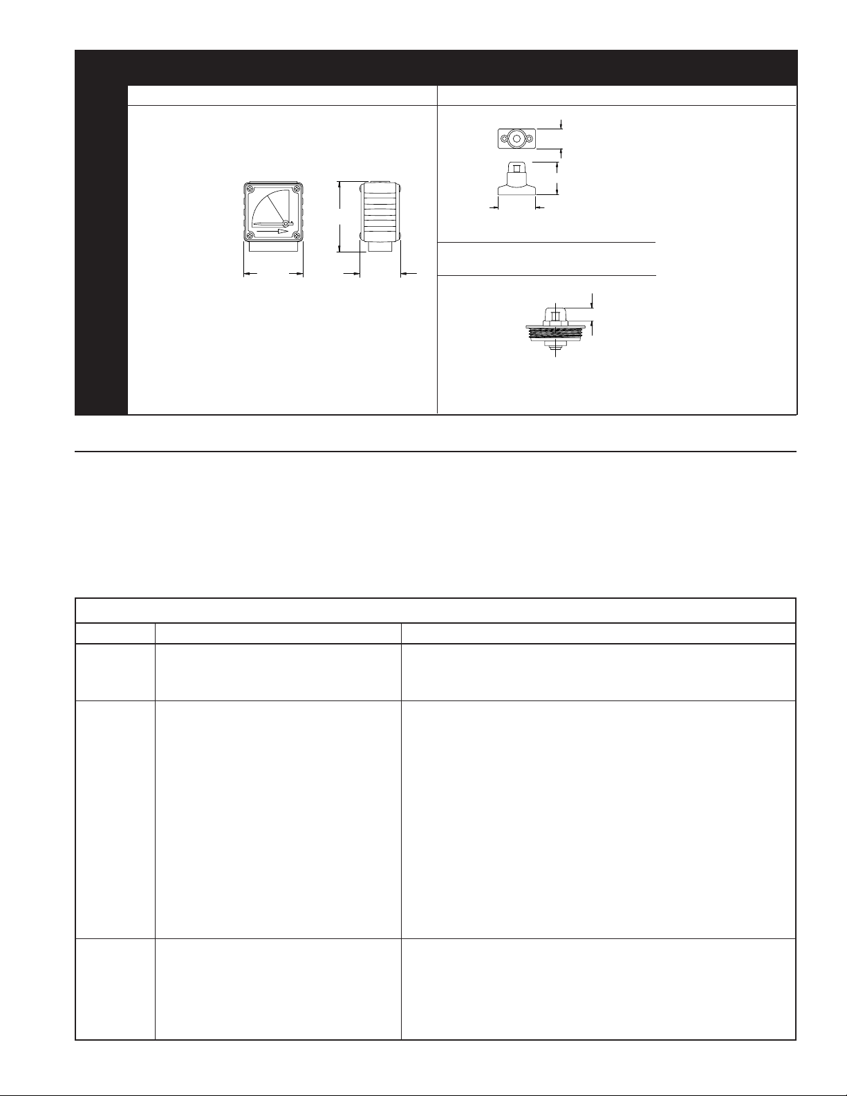
PD-5 (P/N: 84-10001) PD-6 (P/N: 84-10125)
FITS ALL MODELS EXCEPT F200-15-1/4 THRU 25-1/2. FITS ALL MODELS EXCEPT F200-15-1/4 THRU 25-1/2.
*
*
INDICATOR KITS
DIFFERENTIAL PRESSURE
KIT INCLUDES (1) PD-5, (2) SCREWS, (4) O-RINGS &
INSTRUCTION SHEET.
*DIMENSIONS EXTENDING ABOVE FILTER HOUSING.
MAINTENANCE
Drain coalescing lters every shift.
•
Check differential pressures weekly on coalescing and par-
•
ticulate lters (AA, A, B, C, RA, RB, and RC grades). When
the indicator is red on differential pressure indicator, install
clean elements. On adsorbing lters (grade RD), install clean
elements when hydrocarbon vapors are rst detected downstream or every six months, whichever comes rst.
TROUBLE SHOOTING
KIT INCLUDES (1) PD-6, (2) SCREWS, (4) O-RINGS &
INSTRUCTION SHEET.
PD-6A-C (P/N: 84-10126)
PD-6A-P (P/N: 84-10127)
FITS MODELS F200-15-1/4 THRU 25-1/2 ONLY.
PD-6A-C
FOR COALESCING
FILTERS
PD-6A-P
FOR PARTICULATE
FILTERS
KIT INCLUDES (1) PD-6A, (2) O-RINGS & INSTRUCTION SHEET.
*DIMENSIONS EXTENDING ABOVE FILTER HOUSING.
For correct replacement element model numbers, see label
•
*
on lter housing, the bottom endcap of the element, or page
5 of this instruction manual.
When changing out element, inspect housing o-ring for nicks
•
and/or cracks. If nicks and/or cracks are present, replace
o-ring.
CONDITION POTENTIAL CAUSE RECOMMENDATION
Initial pressure
drop too high
Oil carryover Oil present in system before installing lter. Clean piping.
Short element
life
Filter undersized for ow rate. Install larger lter.
Filter grade too ne. Install coarser grade element.
Filter inlet smaller than pipe size. Install larger lter.
Excessive inlet oil >50ppm. Check compressor and/or gas/oil separator if compressor is rotary vane or screw type.
Filter installed backwards. Check ow direction (See page 1).
Filter bowl not being drained. Drain more frequently.
High differential pressure. Check differential pressure indicator, replace element if necessary.
Defective seal. Check o-ring in element.
Incorrect element grade. Use ner grade.
By-pass valve leaking or open. Close valve. Check seals on valve
Unltered gas entering from source down stream of
lter.
High operating temperatures. Install, clean, replace or relocate aftercooler, or relocate lter.
Cooling by refrigerated dryer. Install grade C lter downstream of dryer.
Excessive contamination. Install coarse particulate lter immediately upstream of existing lter.
High compression temperatures causing varnish/
carbon formation.
Oil/water emulsion overloading element. Inspect moisture separator. Remove water with better separation.
High viscosity oil or freeze-up due to low ambient
temperature.
Check lube rate if reciprocating compressor. Install coarse coalescer for preltration.
Relocate lter or install additional lter.
Use compression lubricant with good temperature stability. Lower lube rates where possible. Use coarser grade lter element.
Raise ambient temperatures. Heat trace inlet piping and housing.
PAGE 7
Page 8
Safety is everybody's business and is based on your use of good common sense. All situations or circumstances cannot
SAFETY PRECAUTIONS
always be predicted and covered by established rules. Therefore, use your past experience, watch out for safety hazards
and be cautious.
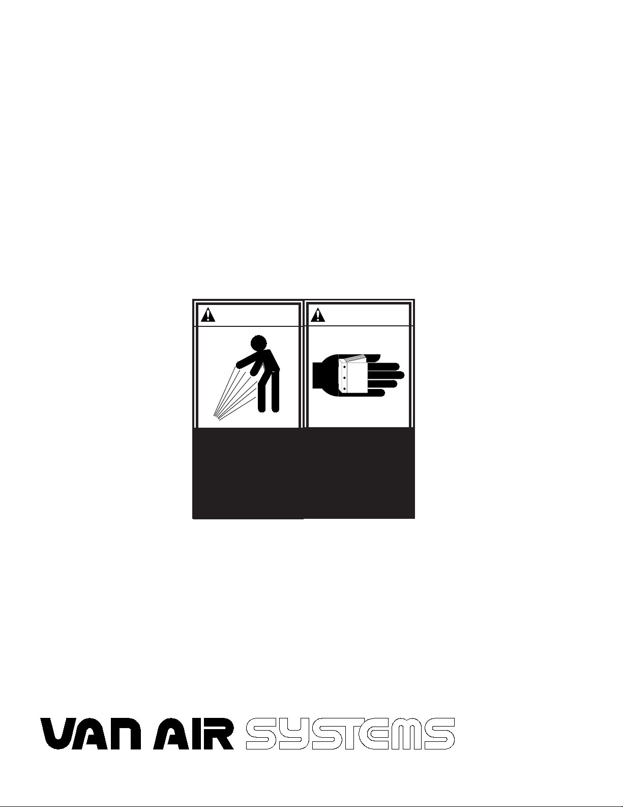
DANGER
AIR AND OIL UNDER PRESSURE
WILL CAUSE SEVERE
PERSONAL INJURY OR DEATH.
SHUT DOWN COMPRESSOR
AND RELIEVE SYSTEM OF ALL
PRESSURE BEFORE REMOVING
VALVES, CAPS, PLUGS,
FITTINGS, BOLTS AND FILTERs.
WARNING
READ THE OPERATOR'S
MANUAL BEFORE STARTING OR
SERVICING THIS UNIT. FAILURE
TO ADHERE TO INSTRUCTIONS
CAN RESULT IN SEVERE
PERSONAL INJURY OR DEATH.
REPLACEMENT MANUALS CAN
BE OBTAINED BY CONTACTING
THE MANUFACTURER.
PAGE 8
2950 Mechanic Street
Lake City, PA 16423-2095
Phone: 800-840-9906
Fax: 814-774-3482
www.vanairsystems.com
 Loading...