

Page 1
INSTALLATION, OPERATION AND
MAINTENANCE INSTRUCTIONS
PIPE LINE DEHYDRATOR FOR NATURAL GAS
PLD 8-2.8 thru PLD 36-2.8
PN 32-0280
REV A
FEBRUARY 2011
WARNING
DO NOT REMOVE, REPAIR OR REPLACE ANY ITEM ON THIS VESSEL WHILE IT IS UNDER
PRESSURE.
DO NOT OPERATE IF THERE IS A LEAK IN VESSEL. IMMEDIATELY TAKE VESSEL OUT OF
SERVICE AND CALL YOUR CERTIFYING AUTHORITY. IF THERE IS A LEAK, DEPRESSURIZE
VESSEL, INSPECT, REPAIR AND OR REPLACE AS NECESSARY.
DO NOT OPERATE ABOVE MAXIMUM WORKING PRESSURE (MWP) AND OR ABOVE MAXIMUM
OPERATING TEMPERATURE (DEGREES OF).
DO NOT WELD OR GRIND VESSEL. IT WILL NOT BE SAFE TO OPERATE.
DO NOT OPERATE IF THE VESSEL HAS BEEN DAMAGED BY FIRE. TAKE OUT OF SERVICE
IMMEDIATELY AND NOTIFY YOUR CERTIFYING AUTHORITY.
ANY DAMAGE TO VESSEL CAN MAKE IT UNSAFE. INSPECT OUTSIDE AND INSIDE OF
VESSEL REGULARLY FOR CORROSION OR ANY DAMAGE (I.E., DENTS, GOUGES OR BULGES).
IF DAMAGED, TAKE OUT OF SERVICE IMMEDIATELY. CALL YOUR CERTIFYING AUTHORITY.
Page 2
1.0 OPERATION
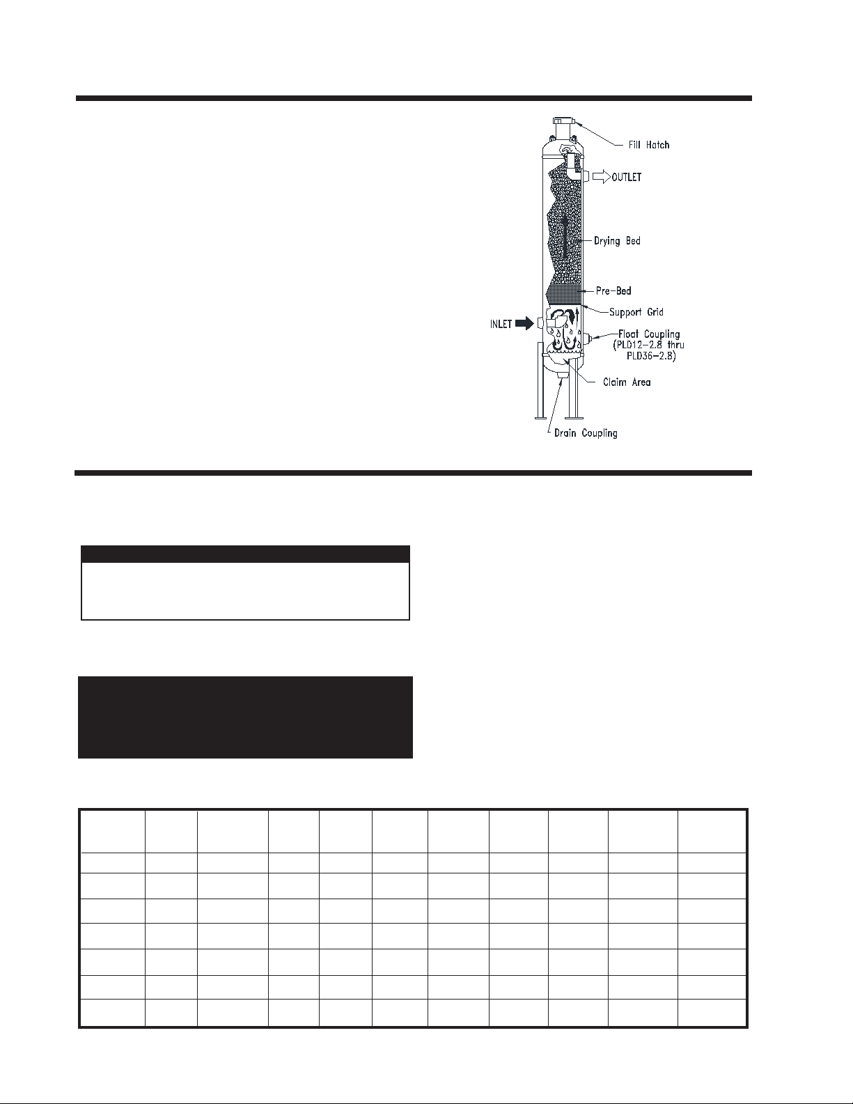
A Pipeline Dehydrator removes the water vapor (humidity) present in the gas stream. The process cleans and dries the gas as it
ows through a vessel which is lled with a special drying agent
(desiccant). The dehydrator operates automatically. There are no
moving parts and no external source of power is required.
"Wet" natural gas enters the lower portion of the dryer where liquid
water and solid particles are separated by gravity and fall to the
bottom of the vessel. The gas moves upward through the prebed
and drying bed of Van Gas desiccant tablets. The tablets attract
and absorb moisture from the gas as it ows through the desiccant
bed. The tablets dissolve gradually as they absorb the moisture
and the liquid falls to the bottom of the vessel. The liquid run off in
the prebed creates an extended surface area capable of removing
additional moisture from the gas. This conserves the absorbent
desiccant tablets. The "dry" natural gas ows through the dryer
outlet.
The solution of dissolved desiccant and water that falls into the
claim area at the bottom of the vessel must be drained regularly to
prevent the vessel from ooding. An automatic drain valve can be
installed to prevent the vessel from ooding.
2.0 INSTALLATION
2.1 LOCATION
The ability of a dehydrator to dry natural gas is dependent on
the correct location of the unit. Temperature and pressure are
the keys to selecting the proper location.
IMPORTANT
ALWAYS PROCESS THE GAS THROUGH THE
DEHYDRATOR AT THE LOWEST TEMPERATURE
AND THE HIGHEST PRESSURE.
INLET GAS TEMPERATURE: Lower inlet gas temperatures will
result in a lower moisture content at the outlet of the dehydrator.
Locate the dehydrator at the point where temperature is the lowest.
CAUTION
The gas temperature should not exceed:
100°F for GASDRY PRIME
80°F for GASDRY PEAK
100°F for GASDRY MAX
MAXIMUM CAPACITIES - MSCFD
1,000 STANDARD CUBIC FEET PER DAY
AFTERCOOLING: If the gas being processed has been compressed
mechanically, an aftercooler, nned tubing or extended run of piping
will usually be necessary to reduce the inlet gas temperature to the
dehydrator.
OPERATING PRESSURE: More gas can be processed through the
dehydrator at higher pressures. Locate the dehydrator at the highest
practical pressure, but do not exceed the maximum rated working
pressure of the dehydrator. Refer to the capacity chart located below.
CAPACITY: The chart below indicates the maximum ow rate
through the dehydrator for a 24 HOUR period. To calculate the
capacity for a rate per minute just multiply the MSCFD RATE (from
chart ) by 0.6944 example:
A PLD 12-2.8 operating at 50 PSIG has a maximum MSCFD rate of
79. To gure the SCFM multiply 79 MSCFD x 0.6944 which equals
54.86SCFM
NOTE: This is the MAX instantanious ow that can be processed
through the dehydrator without deterioration of the drying
performance.
MODEL
NO.
PLD 8-2.8
PLD 12-2.8
PLD 16-2.8
PLD 20-2.8
PLD 24-2.8
PLD 30-2.8
PLD 36-2.8
PAGE 2
PART
NO.
80-1397
80-1399
80-1401
80-1403
80-1405
80-1468
80-1407
MAXIMUM
WORKING
PRESSURE
280 PSIG
280 PSIG
280 PSIG
280 PSIG
280 PSIG
280 PSIG
280 PSIG
50 PSIG
42
79
125
192
280
447
672
100 PSIG
75
141
221
341
497
793
1191
150 PSIG
108
202
317
489
714
1139
1711
175 PSIG
124
233
365
563
822
1312
1970
200 PSIG
141
263
413
638
930
1485
2230
225 PSIG
157
294
462
712
1038
1658
2490
250 PSIG
173
325
510
786
1147
1831
2749
280 PSIG
193
362
567
875
1277
2038
3061
Page 3
2.2 PIPING AND ANCILLARY EQUIPMENT
2.3 INLET AND OUTLET PIPING
IMPORTANT
COMPLY WITH ALL FEDERAL, STATE, AND
LOCAL REGULATIONS CONCERNING
INSTALLATION OF NATURAL GAS SYSTEMS.
COMPLIANCE TO AND KNOWLEDGE OF ALL
REGULATIONS IS THE RESPONSIBILITY OF
THE INSTALLER.
Make sure that the temperature of gas is not over the maximum
for the desiccant being used. If gas temperature is too high, cool it
prior to the dehydrator.
Mount the dehydrator on a level surface capable of supporting the
weight of the vessel, such as a cement pad or a skid.
Install a pressure relief valve in the up-stream piping (relief
valve not furnished). A relief valve must be installed to
conform with the ASME Boiler and Presssure Vessel Codes,
Section VIII, Division 1 UG-125, Paragraph (1) and OSHA
standards. Also comply with all applicable Federal, State,
and Local codes.
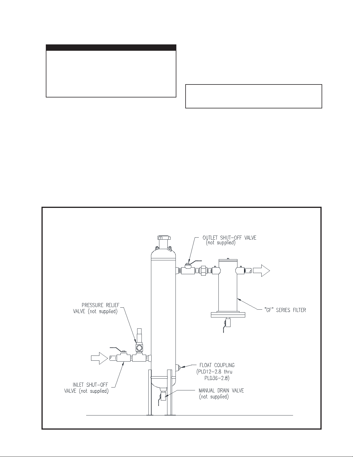
FIGURE 2-A RECOMMENDED INSTALLATION
Two shut-off valves should be installed (not furnished with
dehydrator)-one at dryer inlet and another at dryer outlet. See
Figure 2-A Recommended Installation.
Connect the inlet and outlet piping as shown in Figure 2-A.
NOTE
Inlet and outlet shut-off valves will make start-up
and addition of desiccant easier.
2.4 AFTERFILTER
Van Gas "GF" Series Filters can be installed downstream of the
dehydrator to remove particulate contamination from the natural
gas. Contact Van Gas for details.
2.5 DRAIN VALVE
Install a drain valve (not furnished with dehydrator) in the drain
coupling at the bottom of the tower (except on PLD8-2.8). A oat/
auto drain valve system is available. Contact Van Gas for details.
PAGE 3
Page 4
2.6 INSTALLING DESICCANT
IMPORTANT
DEPRESSURIZE DEHYDRATOR
COMPLETELY BEFORE ATTEMPTING
TO REMOVE FILL COVER.
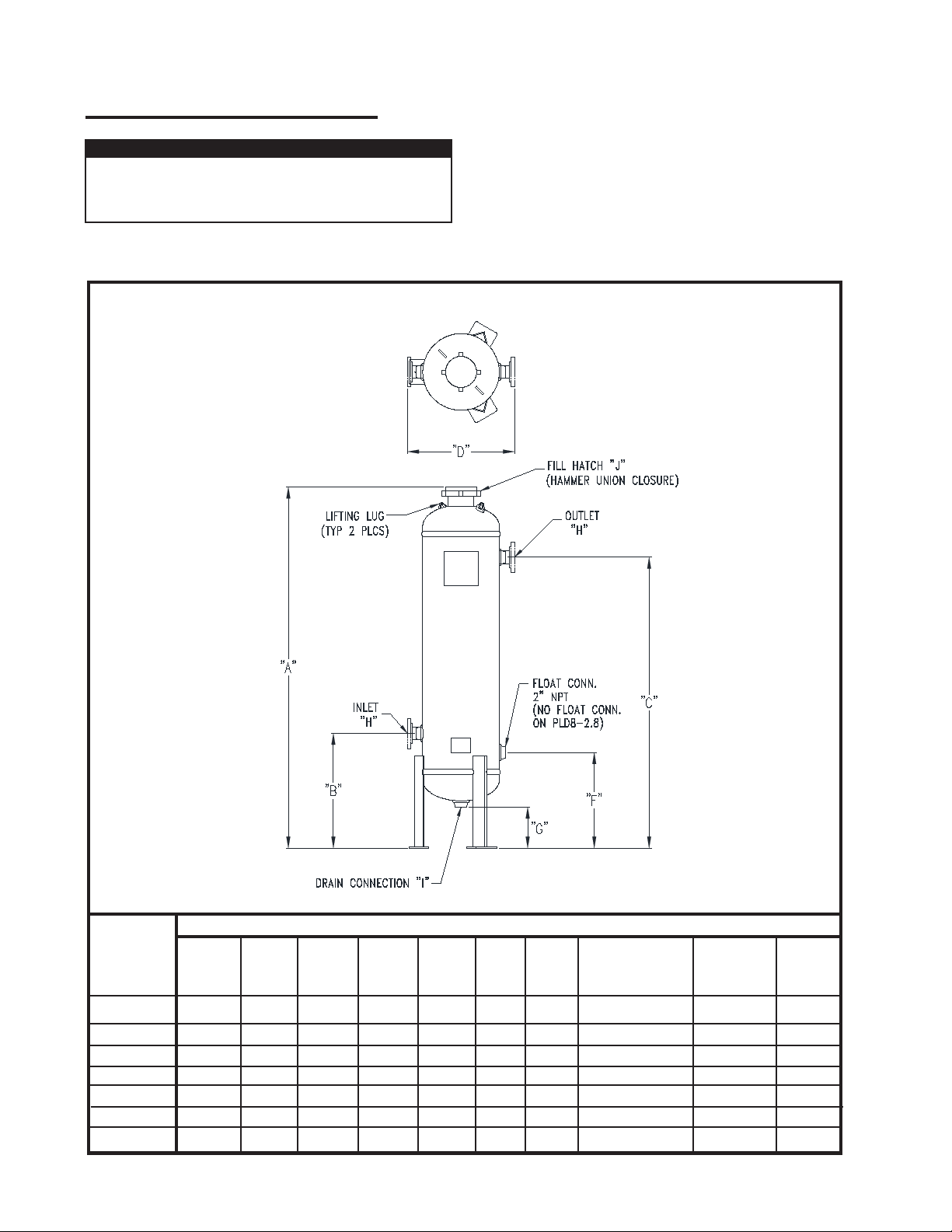
FIGURE 2-B DIMENSIONS
Open ll cover and add the proper amount of pre-bed material and
desiccant to ll the dehydrator to the MAXIMUM LEVEL; then level
off the top off the bed.
(Reference SECTION 4.3 for desiccant installation instructions)
USE VAN GAS ABSORBENT DESICCANT ONLY!
Close ll cover. Make sure that the inlet and outlet shut-off
valves, and manual drain valve are closed.
MODEL
PLD 8-2.8
PLD 12-2.8
PLD 16-2.8
PLD 20-2.8
PLD 24-2.8
PLD 30-2.8
PLD 36-2.8
PAGE 4
A
Overall
Height
47-1/4"
73-13/16"
74-1/8"
76-5/8"
74"
80-3/16"
81-3/16"
DRYER DIMENSIONS-INCHES
B
Inlet
Height
13"
30"
30"
30"
25-3/8"
30"
29-5/16"
C
Outlet
Height
36"
58"
58"
58"
52-7/8"
57-1/2"
56-13/16"
D
In to Out
Width
13-1/8"
18"
21-1/4"
23"
36"
42"
48-3/4"
Outside
8-5/8"
12-3/4"
36-3/4"
E
Dia.
16"
20"
24"
30"
F
Float
Height
N/A
25"
25"
25"
20-3/8"
25"
24-5/16"
G
Drain
Height
2-7/16"
14"
13-5/8"
11-5/8"
6-1/8"
9-1/4"
6-7/8"
H
Inlet
/Outlet
2" NPT
2" NPT
2" NPT
2" NPT
3" RF FLG 150#
3" RF FLG 150#
3" RF FLG 150#
I
Drain
1" NPT
2" NPT
2" NPT
2" NPT
2" NPT
2" NPT
2" NPT
J
Hammer
Union
4"
4"
4"
6"
6"
6"
6"
Page 5

3.0 OPERATION
3.1 START-UP
Close dehydrator drain valve. See Figure 2-A Recommended
Installation.
SLOWLY pressurize by opening the inlet shutoff valve (if installed).
Open the outlet shutoff valve (if installed) slowly to place dehydrator
on stream.
CAUTION
Make sure that the dehydrator is not subjected
to sudden ow surges. Always open valves
slowly to permit a gradual equalization of
pressure between the dehydrator and the gas
supply lines.
4.0 MAINTENANCE
4.1 MAINTENANCE
WARNING
IF DRYER IS NOT DRAINED REGULARLY,
FLOODING WILL OCCUR AND ACCUMULATED
LIQUID MAY ENTER SYSTEM AND DAMAGE
DOWNSTREAM EQUIPMENT.
4.2 INSPECT DESSICCANT BED LEVEL
Check bed level monthly until the actual usage rate is determined.
During the drying process, the desiccant tablets dissolve slowly. More
tablets must be added to the supply when the top of the bed drops
to the MINIMUM LEVEL. The consumption rate is dependent upon
several factors, such as inlet temperature and ow. In Section 4.5,
DESICCANT CONSUMPTION, are several charts showing desiccant
consumption rates. Use the charts to determine an approximate
usage rate for your application.
NOTE
Use VAN GAS desiccants only. Filling dryer with
any other material will void the warranty.
4.3 ADDITION OF DESICCANT
Close dryer inlet and outlet shut-off valves (If installed). Open drain
valve and allow dryer to depressurize completely.
Use a solution of soapy water to check all pipe and tting
connections made during installation for leaks. If any leaks are
present, immediately depressurize the system and remedy the
problem before continuing operation.
3.2 SHUTDOWN
Before shutdown, use the manual drain valve to remove any liquid
that has accumulated in the sump area of the vessel.
Close dryer inlet and outlet shutoff valves (if installed). Open drain
valve to depressurize the vessel.
Remove the ll cover.
Using the chart in Figure 4-A, determine the proper quantity of
prebed.
Place the prebed into the dehydrator rst. Level off the prebed.
Again using the chart in Figure 4-A determine the correct quantity
and type of desiccant required to ll the dehydrator.
Slowly pour the desiccant into the dehydrator. Level off the desiccant bed. The desiccant level should NOT be higher than the
OUTLET screen.
Replace the ll cover.
WARNING
WHEN HATCH COVER IS REMOVED TO ADD
DESICCANT, ALWAYS CHECK O-RING FOR
SIGNS OF WEAR.
CHECK COVER FOR RUST, CORROSION OR
DAMAGE; REPLACE AS NEEDED.
SEE SECTION 6 FOR REPLACEMENT PARTS.
WARNING
COMPLETELY DEPRESSURIZE DRYER
BEFORE ATTEMPTING TO REMOVE FILL
COVER.
Close the drain valve.
Slowly open the inlet shut-off valve (if installed) to pressurize
the dehydrator.
Open the outlet shut-off valve (if installed) and place the dehydrator
on stream.
PAGE 5
Page 6
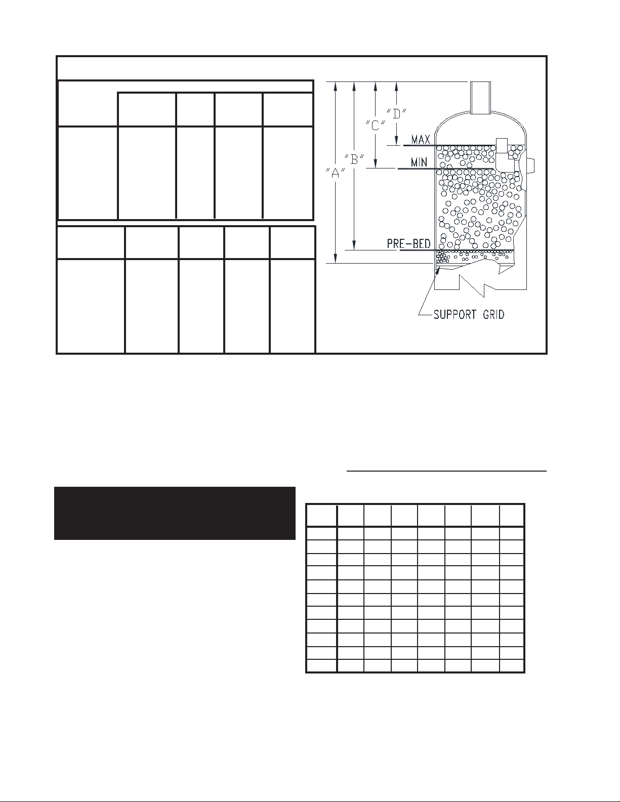
FIGURE 4-A BED LEVEL DETAIL
DRYER DIMENSIONS-INCHES
MODEL
PLD 8-2.8
PLD 12-2.8
PLD 16-2.8
PLD 20-2.8
PLD 24-2.8
PLD 30-2.8
PLD 36-2.8
A
Dim. To
Grid
29-1/2"
36-1/2"
37-1/8"
39-3/8"
40-3/8"
41-7/8"
43-5/8"
B
Dim. To
Pre-Bed
23-1/2"
30-1/2"
31-1/8"
33-3/8"
34-3/8"
35-7/8"
37-5/8"
C
Dim. To
MIN LEVEL
15-1/2"
14-1/2"
15-1/8"
17-3/8"
18-3/8"
19-7/8"
21-5/8"
D
Dim. To
MAX LEVEL
12-1/4"
7-1/2"
7-3/8"
9-3/8"
10-3/8"
11-7/8"
13-5/8"
MODEL
PLD 8-2.8
PLD 12-2.8
PLD 16-2.8
PLD 20-2.8
PLD 24-2.8
PLD 30-2.8
PLD 36-2.8
PRE-BED
CERAMIC
BEAD
17 LBS
38 LBS
59 LBS
91 LBS
133 LBS
212 LBS
318 LBS
DRYING
GASDRY
PRIME
25 LBS
115 LBS
187 LBS
291 LBS
425 LBS
678 LBS
1018 LBS
DRYING
GASDRY
PEAK
19 LBS
88 LBS
143 LBS
222 LBS
324 LBS
518 LBS
778 LBS
4.4 BED LEVEL GUIDE
The level of the desiccant bed should be maintained as close to
the MAXIMUM level as possible. The bed level should not be
allowed to fall below the MINIMUM level. Dehydrator performance
will be effected. Reference Figure 4-A for levels and quantities.
With the ll port cover removed, use a measuring stick to determine the distance from the top of the ll opening to the top of the
desiccant bed. Reference Figure 4-A. Add desiccant as required
to bring desiccant bed to maximum level.
CAUTION
Never ll the vessel above the MAXIMUM LEVEL.
Filling the vessel above the MAXIMUM level may
effect the performance of the dehydrator.
The desiccant bed level should be checked regularly. Section
4.4 DESICCANT CONSUMPTION will help you estimate the
amount of desiccant that the dehydrator should use based on
operating conditions.
4.5 DESICCANT CONSUMPTION
Consumption rate based on average conditions. Actual conditions can vary.
4.5-A GASDRY PRIME DESICCANT
This general purpose tablet is recommended for installations
where inlet gas temperature is 100oF or lower. Depending on the
pressure and temperature, GasDry Prime can provide a residual
moisture content below 19 lbs/mmscf.
DRYING
GASDRY
MAX
21 LBS
96 LBS
156 LBS
243 LBS
354 LBS
565 LBS
848 LBS
Chart 1 shows the level of dryness that GasDry Prime will provide
at different conditions.
Chart 2 shows an approximate consumption rate for GasDry Prime
at several conditions. Use the charts for guidelines to calculate
the approximate consumption rate of the desiccant.
CHART 1
MOISTURE CONTENT OF GAS (LBS. H2O/MMSCF)
AFTER DEHYDRATOR WITH GASDRY PRIME
INLET
TEMP
100oF
95oF
90oF
85oF
80oF
75oF
70oF
65oF
60oF
55oF
50oF
50
PSIG
391.8
336.5
288.9
246.5
210.2
178.1
150.3
126.9
106.9
89.0
74.4
100
PSIG
224.7
193.1
165.9
141.6
120.8
102.5
86.6
73.2
61.7
51.4
43.0
150
PSIG
159
136.7
117.6
100.4
85.7
72.8
61.5
52.0
43.9
36.7
30.7
175
PSIG
139.2
119.7
103.0
87.9
75.1
63.8
53.9
45.7
38.6
32.2
27.0
200
PSIG
124.0
106.6
91.7
78.4
67.0
56.9
48.2
40.8
34.4
28.8
24.1
250
PSIG
102.1
87.9
75.7
64.7
55.3
47.0
39.8
33.8
28.5
23.9
20.0
280
PSIG
92.6
79.8
68.7
58.7
50.2
42.7
36.2
30.7
26.0
21.7
18.2
PAGE 6
NOTE
MMSCF is 1,000,000 STANDARD CUBIC FEET
Page 7

CHART 2
GASDRY PRIME CONSUMPTION RATE
(LBS./MMSCF)
INLET
TEMP
100oF
95oF
90oF
85oF
80oF
75oF
70oF
65oF
60oF
55oF
50oF
50
PSIG
71.2
61.2
52.5
44.8
38.2
32.4
27.3
23.1
19.4
16.2
13.5
100
PSIG
40.9
35.1
30.2
25.8
22.0
18.6
15.7
13.3
11.2
9.4
7.8
150
PSIG
28.9
24.9
21.4
18.3
15.6
13.2
11.2
9.5
8.0
6.7
5.6
175
PSIG
25.3
21.8
18.7
16.0
13.7
11.6
9.8
8.3
7.0
5.9
4.9
200
PSIG
22.5
19.4
16.7
14.3
12.2
10.4
8.8
7.4
6.3
5.2
4.4
250
PSIG
18.6
16.0
13.8
11.8
10.1
8.6
7.2
6.1
5.2
4.3
3.6
280
PSIG
16.8
14.5
12.5
10.7
9.1
7.8
6.6
5.6
4.7
4.0
3.3
4.5-B GASDRY PEAK DESICCANT
The general purpose tablet is reccommended for installations where
inlet gas temperature is 80oF or lower. Depending on the pressure and
temperature, GasDry Peak can provide a residual moisture content
below 10 lbs/MMSCF.
Chart 3 shows the level of dryness that GasDry Peak provides at
different conditions.
Chart 4 shows an approximate consumption rate for GasDry Peak
at several conditions. Use the charts for guidelines to calculate the
approximate consumption rate of the desiccant.
CHART 3
MOISTURE CONTENT OF GAS (LBS. H2O/MMSCF)
AFTER DEHYDRATOR WITH GASDRY PEAK
INLET
TEMP
80oF
75oF
70oF
65oF
60oF
55oF
50oF
45oF
CHART 4
50
PSIG
126.1
106.9
90.2
76.1
64.1
53.4
44.6
37.0
100
PSIG
72.5
61.5
51.9
43.9
37.0
30.9
25.8
21.5
150
PSIG
51.4
43.7
36.9
31.2
26.3
22.0
18.4
15.3
175
PSIG
45.1
38.3
32.4
27.4
23.1
19.3
16.2
13.5
200
PSIG
40.2
34.2
28.9
24.5
20.7
17.3
14.5
12.0
250
PSIG
33.2
28.2
23.9
20.3
17.1
14.3
12.0
10.0
280
PSIG
30.1
25.6
21.7
18.4
15.6
13.0
10.9
9.1
GASDRY PEAK CONSUMPTION RATE (LBS./MMSCF)
INLET
TEMP
80oF
75oF
70oF
65oF
60oF
55oF
50oF
45oF
50
PSIG
116.4
98.6
83.2
70.3
59.2
49.3
41.2
34.2
100
PSIG
66.9
56.7
47.9
40.5
34.1
28.5
23.8
19.8
150
PSIG
47.5
40.3
34.1
28.8
24.3
20.3
17.0
14.1
175
PSIG
41.6
35.3
29.9
25.3
21.3
17.8
14.9
12.4
200
PSIG
37.1
31.5
26.7
22.6
19.1
15.9
13.3
11.1
250
PSIG
30.6
26.0
22.0
18.7
15.8
13.2
11.1
9.2
280
PSIG
27.8
23.7
20.0
17.0
14.4
12.0
10.1
8.4
4.5-B GASDRY MAX DESICCANT
Where extremely dry gas is required or where operating pressure is
low, GasDry Max tablets provide a lower residual moisture content.
Chart 5 shows the level of dryness that GasDry Max will provide at
different conditions.
Chart 6 shows an approximate consumption rate for GasDry Max
at several conditions. Use the charts for guidelines to calculate the
approximate consumption rate of the desiccant.
CHART 5
MOISTURE CONTENT OF GAS (LBS.H2O/MMSCF)
AFTER DEHYDRATOR WITH GASDRY MAX
INLET
TEMP
100oF
95oF
90oF
85oF
80oF
75oF
70oF
65oF
60oF
55oF
50oF
45oF
40oF
CHART 6
50
PSIG
92.6
79.5
68.3
58.3
49.7
42.1
35.5
30.0
25.3
21.0
17.6
14.6
12.1
100
PSIG
53.1
45.6
39.2
33.5
28.6
24.2
20.5
17.3
14.6
12.2
10.2
8.5
7.0
150
PSIG
37.6
32.3
27.8
23.7
20.3
17.2
14.5
12.3
10.4
8.7
7.3
6.0
5.0
175
PSIG
32.9
28.3
24.3
20.8
17.8
15.1
12.8
10.8
9.1
7.6
6.4
5.3
4.4
200
PSIG
29.3
25.2
21.7
18.5
15.8
13.5
11.4
9.6
8.1
6.8
5.7
4.7
3.9
250
PSIG
24.1
20.8
17.9
15.3
13.1
11.1
9.4
8.0
6.7
5.6
4.7
3.9
3.3
280
PSIG
21.9
18.9
16.2
13.9
11.9
10.1
8.6
7.3
6.1
5.1
4.3
3.6
3.0
GASDRY MAX CONSUMPTION RATE (LBS./MMSCF)
INLET
TEMP
100oF
95oF
90oF
85oF
80oF
75oF
70oF
65oF
60oF
55oF
50oF
45oF
40oF
50
PSIG
206.6
177.4
152.3
130.0
110.8
93.9
79.3
66.9
56.3
47.0
39.2
32.5
26.9
100
PSIG
118.5
101.8
87.5
74.7
63.7
54.0
45.6
38.6
32.5
27.1
22.7
18.9
15.6
150
PSIG
83.8
72.1
62.0
53.0
45.2
38.4
32.5
27.4
23.1
19.3
16.2
13.5
11.1
175
PSIG
73.4
63.1
54.3
46.4
39.6
33.6
28.4
24.1
20.3
17.0
14.2
11.8
9.8
200
PSIG
65.4
56.2
48.4
41.4
35.3
30.0
25.4
21.5
18.2
15.2
12.7
10.6
8.8
250
PSIG
53.9
46.4
39.9
34.1
29.2
24.8
21.0
17.8
15.1
12.6
10.6
8.8
7.3
280
PSIG
48.8
42.1
36.2
31.0
26.5
22.5
19.1
16.2
13.7
11.5
9.6
8.0
6.7
NOTE
MMSCF is 1,000,000 STANDARD CUBIC FEET
PAGE 7
Page 8
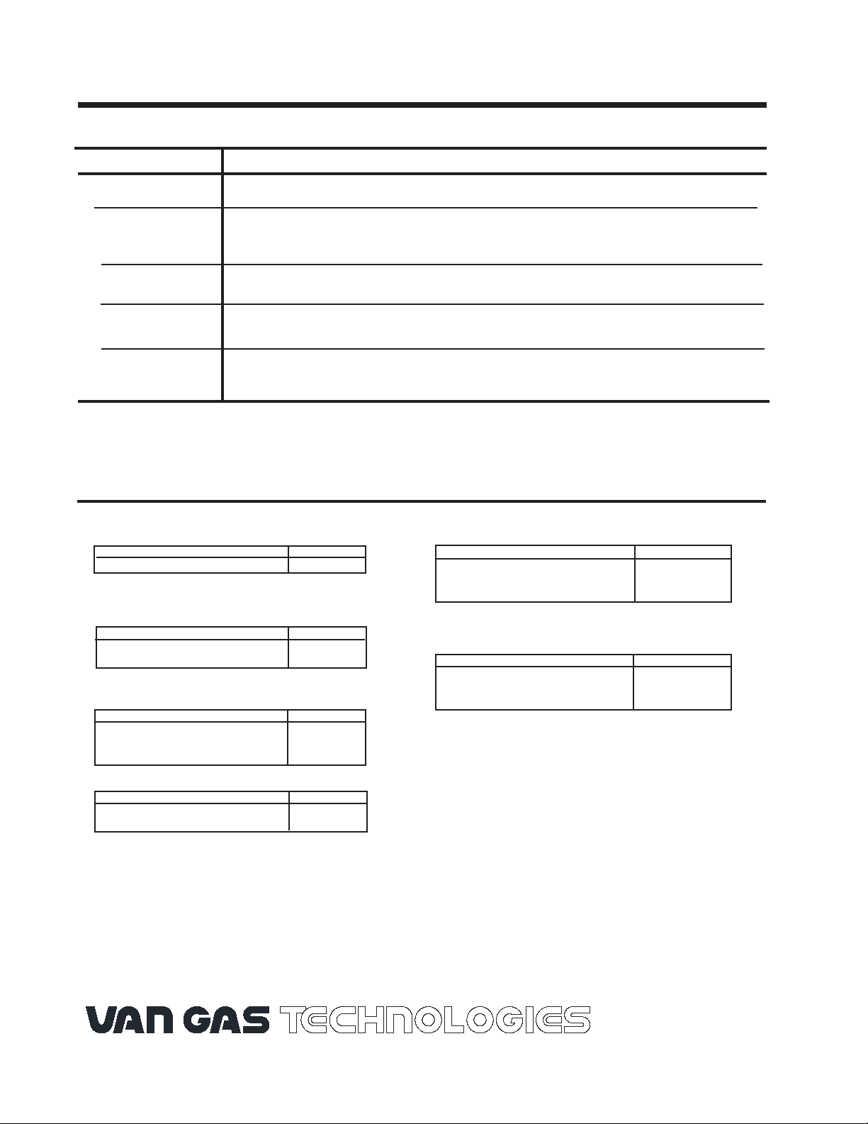
5.0 TROUBLESHOOTING CHECK LIST
If liquid water is detected downstream or if desiccant consumption seems excessively high, the most likely causes are as
follows:
Problem
Possible Cause
Liquid downstream The frequency of draining is not adequate.
Check inlet Temperature. Conditions may have changed. Determine the cause.
High inlet
temperature
Low desiccant
If gas is compressed mechanically, check compressor aftercooler.
Check bed level to make sure that desiccant tablet level has not dropped below minimum level.
level
Incorrect flow
and/or pressure
Contaminated
Desiccant bed
If correcting conditions in the troubleshooting check list does not remedy the problem, consult your local VAN GAS Distributor or call the
VAN GAS factory in Lake City, Pennsylvania (888)-606-9303 or (814)-774-2636.
Check ow through dehydrator, refer to chart on page 2.
Check inlet pressure.
Inspect condition of desiccant. If discolored (deep yellow or brown), it may be contaminated.
A heavily contaminated desiccant bed must be replaced to return dehydrator to optimum performance.
6.0 REPLACEMENT PARTS LIST
DESICCANTS
CERAMIC BEAD (PREBED)
DESCRIPTION PART NO.
90 LB. CARTON 33-0281
GASDRY PRIME(DRYING)
DESCRIPTION PART NO.
50 LB. PAIL 33-0355
50 LB. BAG 33-0354
GASDRY PEAK(DRYING)
DESCRIPTION PART NO.
45 LB. PAIL 33-0328
50 LB. BAG 33-0205
400 LB. DRUM 33-0283
PLD 8, PLD 12, AND PLD 16 DEHYDRATOR
DESCRIPTION PART NO.
BLIND PLATE 26-7126
HAMMER UNION NUT 26-7128
FILL COVER O-RING 26-7573
PLD 20, PLD 24, AND PLD 36 DEHYDRATOR
DESCRIPTION PART NO.
BLIND PLATE 26-7127
HAMMER UNION NUT 26-7129
FILL COVER O-RING 26-3640
DESCRIPTION PART NO
7 LB. PAIL 33-0318
25 LB. PAIL 33-0232
GasDry Prime, GasDry Peak, and GasDry Max are the registered trade names of chemical drying agents specically formulated by and
for VAN GAS Single Tower Dehydrators.
GASDRY MAX (DRYING)
2950 Mechanic Street
Lake City, Pa 16423 USA
Phone: 800-840-9906
Fax: 814-774-0778
www.vangastech.com
 Loading...