

Page 1
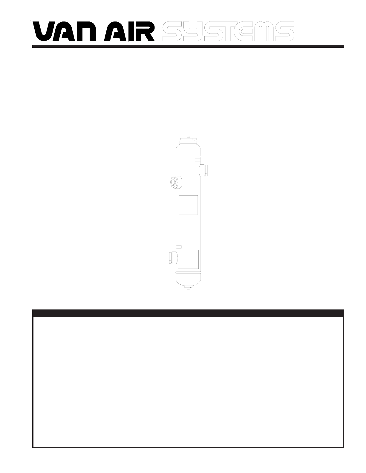
INSTALLATION & OPERATION INSTRUCTIONS
FOR
COMPRESSED AIR/GAS
IN-LINE DESICCANT DRYER
MODEL
ID-35 (P/N 80-1364)
September 2009
P/N 32-0288-B
WARNING
DO NOT REMOVE, REPAIR, OR REPLACE ANY ITEM ON THE DRYER WHILE IT IS PRESSURIZED. DEPRESSURIZE THE
DRYER COMPLETELY BEFORE STARTING INSTALLATION AND/OR MAINTENANCE PROCEDURES. SERIOUS
PERSONAL INJURY MAY RESULT IF THESE SAFETY RULES ARE NOT FOLLOWED.
DO NOT OPERATE THIS PRESSURE VESSEL ABOVE MAXIMUM WORKING PRESSURE (MWP) AND/OR MAXIMUM
OPERATING TEMPERATURE (OF) AS SHOWN ON THE ASME DATA PLATE.
THIS ASME CODE VESSEL MUST BE PROTECTED BY A PRESSURE RELIEF VALVE. Refer to OSHA 1910.169 Par.
b, Sub. Par (3) and ASME Boiler and Pressure Vessel Code, Section VIII, Division 1, UG-125 through UG-136. Also
comply with all applicable state and local codes.
DO NOT WELD, GRIND, OR SAND VESSEL, OR IT WILL NOT BE SAFE TO OPERATE. (Note: Any alteration to the
vessel will void the ASME Code Certification and the warranty.)
INSPECT OUTSIDE AND INSIDE OF VESSEL REGULARLY FOR CORROSION AND DAMAGE (I.E., DENTS GOUGES
OR BULGES). ANY DAMAGE TO THE VESSEL CAN MAKE IT SAFE TO USE. IF DAMAGED, TAKE OUT OF SERVICE
IMMEDIATELY.
USE THE PROPER SAFETY RULES FOR THE GAS BEING PROCESSED.
DO NOT REMOVE THE FILL PORT UNTIL ALL PRESSURE IS OUT OF THE VESSEL.
PAGE 1
Page 2
SECTION 1 SPECIFICATIONS
1.0 PURPOSE OF OPERATION
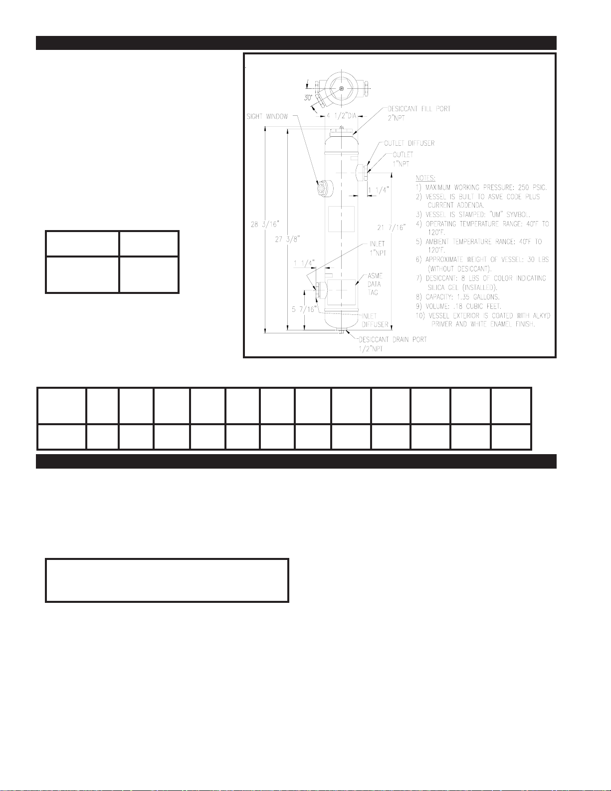
The Van Air In-Line Desiccant Dryer is designed to
be filled with adsorbent desiccant such as silica gel.
The saturated air or gas enters the bottom side
connection (inlet) on the vessel and travels through
the bed of adsorbent material.
Dry air or gas exits the top side connection (outlet)
on the vessel.
FIGURE 1 DRYER DETAILS
FIGURE 3 DRYING TIME USING SILICA GEL
(at rated flow at 100 PSIG)
INLET
TEMPERATURE
60°F
80°F
100°F
TIME
(MINUTES)
542
283
156
FIGURE 2 MAXIMUM CAPACITIES -SCFM (Nm3/hr)
MAXIMUM
WORKING
PRESSURE
250 PSIG
5 PSIG
0.3 Bar
6
9.6
10 PSIG
0.7 Bar
7.5
12.1
20 PSIG
1.4 Bar
10.5
16.9
40 PSIG
2.8 Bar
17
27.3
60 PSIG
4.1 Bar
23
37.0
80 PSIG
5.5 Bar
29
46.6
90 PSIG
6.2 Bar
32
51.4
100 PSIG
6.9 Bar
35
56.3
125 PSIG
8.6 Bar
43
69.1
150 PSIG
10.3 Bar
80.4
50
200 PSIG
13.8 Bar
66
106.1
250 PSIG
17.2 Bar
81
130.2
SECTION 2 INSTALLATION
2.1 LOCATION
Proper performance depends on the correct location of the unit. Locate
the dryer at the lowest temperature and highest pressure possible in the
system. If there is a pressure regulator in the system, install the dryer
upstream of the regulator.
Make sure that the system pressure does not exceed the 250 PSIG
maximum working pressure of the vessel.
IMPORTANT
ALWAYS PROCESS AIR THROUGH THE DRYER AT THE
LOWEST POSSIBLE TEMPERATURE AND THE HIGHEST
PRACTICAL PRESSURE.
2.2 PIPING AND ANCILLARY EQUIPMENT
If the dryer is being installed in an existing piping system, make sure
that the pipe is free of scale and rust.
The dryer is supported by the piping system. Adequate pipe supports
must be used to prevent damage to the pipeline and dryer.
2.2-A ISOLATION VALVES
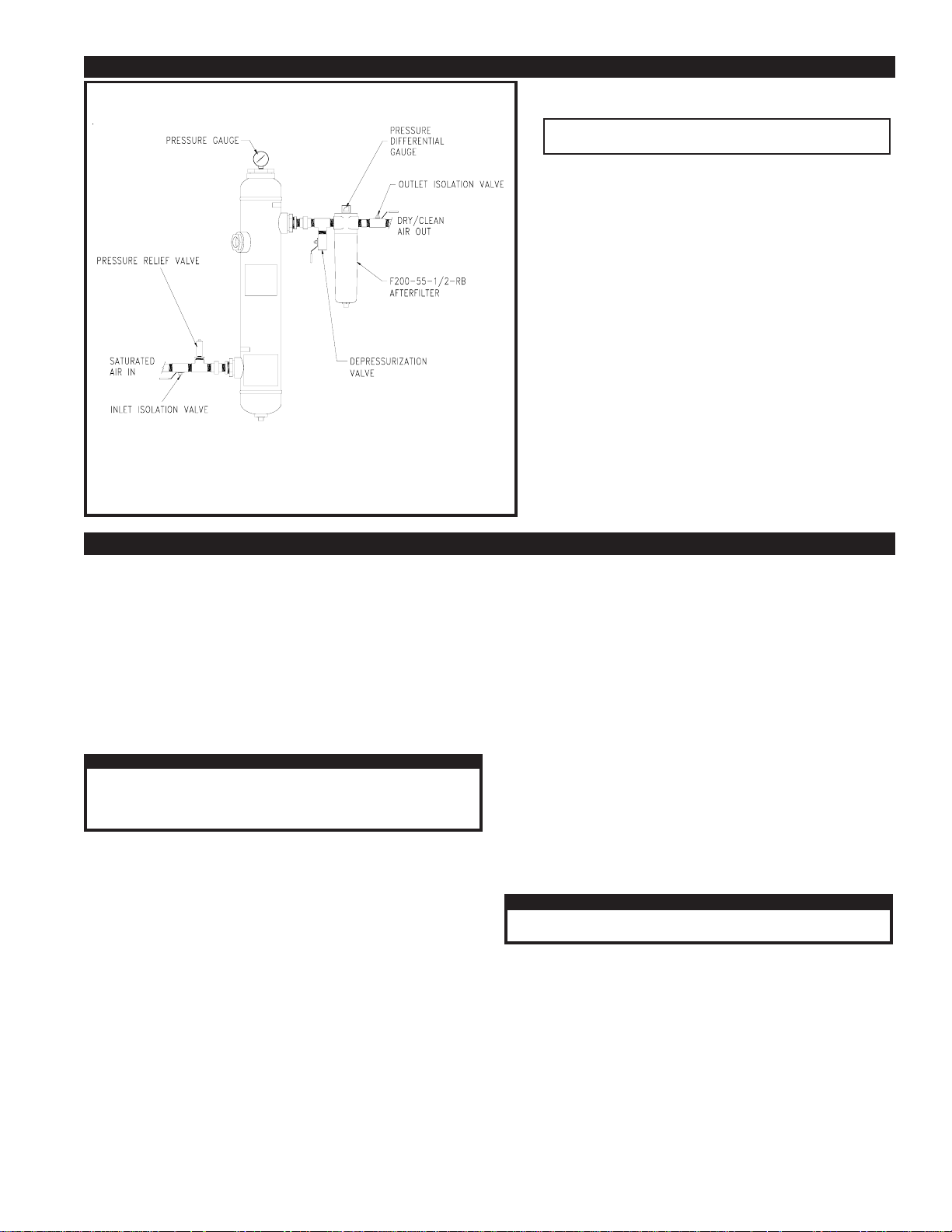
Using Figure 3 as a reference, make the necessary piping connections
into the dryer.
Inlet and outlet isolation valves are required to isolate the dryer when
the adsorbent material is changed.
PAGE 2
These valves will also aid in start up and shutdown of the dryer. The
inlet isolation valve should be mounted before the pressure relief
valve. The outlet isolation valve should be installed on the dryer
outlet. A manual valve and a tee should be installed on either the inlet
or outlet side of the dryer to depressurize the unit.
A bypass is not recommended, as contamination can go downstream
while the unit is maintained. The bypass valve can also accidentally
be left open.
2.2-B OPTIONAL PRESSURE RELIEF VALVE (p/n 14-2213)
A pressure relief valve should be installed to conform to OSHA
safety standards. Refer to OSHA Standard Section 1910.169,
paragraph “b”, subparagraph “3”. Also comply with all applicable
federal, state and local codes concerning pressure vessels.
2.2-C OPTIONAL PRESSURE GAUGE (p/n 29-0160)
An optional pressure gauge is available to mount in the 1/4" NPT
connection on the fill port.
2.2-D AFTERFILTER (p/n 84-23256)
The installation of an F200-55-1/2-RB-MD-PD6 afterfilter prevents
any adsorbent material from going downstream.
The afterfilter should be installed upstream of the outlet isolation
valve. This will allow the filter to be isolated from the air system
when the dryer is isolated for maintenance.
Page 3
SECTION 2 INSTALLATION
FIGURE 3 RECOMMENDED INSTALLATION DRAWING
2.2-E DESICCANT INSTALLATION
IMPORTANT
NOTE:
ITEMS CALLED OUT IN THIS DRAWING
ARE NOT SUPPLIED WITH THE DRYER.
REFERENCE FIGURE 1 FOR ITEMS
INCLUDED WITH DRYER.
This dryer was shipped WITH the desiccant installed.
See Section 3.3 of this manual for desiccant replacement.
SECTION 3 OPERATION
3.1 START UP PROCEDURES
Make sure all isolation valves are closed.
3.3 REPLACING THE ADSORBENT DESICCANT
Close the inlet and outlet isolation valves (if installed).
Pressurize the system.
SLOWLY open the inlet isolation valve to bring the unit up to line
pressure.
SLOWLY open the outlet isolation valve to put the unit on stream.
If the vessel was installed without isolation valves, SLOWLY pressurize
the air system.
CAUTION
Make sure that the dryer is not subjected to sudden flow
surges. Always open valves slowly to permit gradual
equalization of pressure between the dryer and the air supply
lines.
3.2 OPERATING THE DRYER
On a new installation, drain all downstream traps for several days (or
until no water is evident) after dryer is installed. This period is required
to dry out any accumulated water in the compressed air system. Once
the water is removed, the downstream traps should not need to be
drained again.
If silica gel desiccant is used in the vessel, it should be replaced when
the color in the sight window changes. Pink silica gel is moist and blue
silica gel is dry.
If other adsorbents are used, they should be replaced on a scheduled
basis, or when downstream measurement equipment indicates it.
Slowly open the depressurization valve to completely depressurize the
unit.
Remove the desiccant drain plug from the bottom of the vessel and
drain the old desiccant.
Replace the drain plug. Use pipe thread compound as needed.
Remove the fill port plug from the top of the vessel.
Fill the vessel with adsorbent desiccant. It takes approximately 8
pounds of indicating silica gel to fill the vessel.
Replace the fill port plug.
Start up the dryer per section 3.1.
3.3 USING THE SIGHT WINDOW
WARNING
IF SIGHT WINDOW IS DAMAGED IN ANY WAY, REPLACE IT
IMMEDIATELY WITH VAN AIR PART NO. 26-0104 only.
When using indicating silica gel, look into the sight window to check the
color of the desiccant bed. Pink silica gel is moist and blue silica gel is
dry. Replace the silica gel when the sight window shows pink.
PAGE 3
Page 4
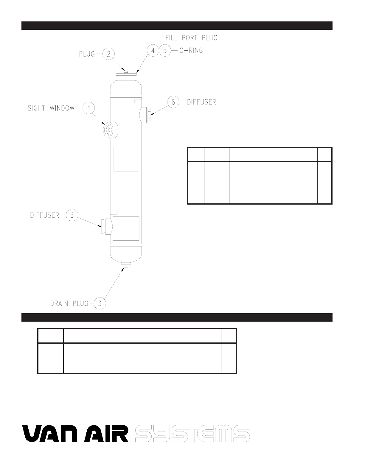
SECTION 4 PARTS
ITEM
1
2
3
4
5
6
7
PART NO.
26-0104
14-0308
14-0320
14-2188
26-10264
26-8978
33-0246
DESCRIPTION
Sight Window
Plug
Drain Plug
Fill Port Plug
O-Ring
Diffuser
Desiccant 25# Pail, indicating silica gel
QTY
1
1
1
1
1
2
1
SECTION 5 ACCESSORIES
PART NO.
84-23256
26-2103
29-0160
14-2213
14-0450
SEE FIGURE 3 FOR LOCATION OF ACCESSORIES
PAGE 4
F200-55-1/2-RB-MD-PD6 Afterfilter with differential pressure indicator
E200-55-RB Afterfilter Element
Pressure Gauge (0-300 PSIG)
Pressure Relief Valve
Ball Valve 1/2" NPT
DESCRIPTION
QTY
1
1
1
1
3
2950 Mechanic Street
Lake City, PA 16423 USA
Phone: 800-840-9906
Fax: 814-774-3482
www.vanairsystems.com
 Loading...