

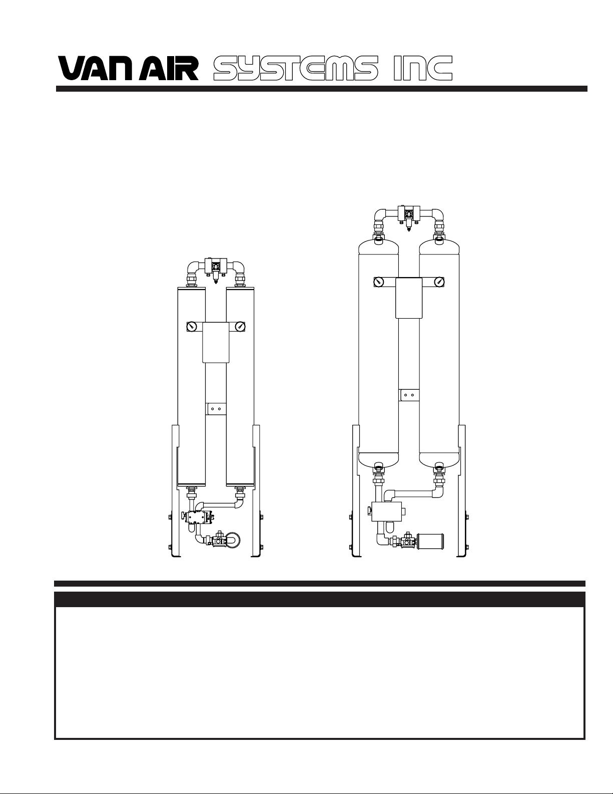
INSTALLATION, OPERATION & MAINTENANCE MANUAL
FOR
HEATLESS REGENERATIVE
COMPRESSED AIR DRYER
models
HLS-55 through HLS-150
SEPTEMBER 2004
P/N 32-0266-C
2950 MECHANIC STREET
LAKE CITY, PA 16423
PHONE:814-774-2631
FAX: 814-774-3482
HLS-55/80
HLS-120/150
WARNING
READ ALL INFORMATION IN THIS MANUAL BEFORE BEGINNING INSTALLATION OR OPERATION OF THE
DRYER. BEFORE STARTING INSTALLATION AND/OR MAINTENANCE PROCEDURES, TURN OFF THE MAIN
POWER TO THE DRYER AND COMPLETELY DEPRESSURIZE THE UNIT TO PREVENT PERSONAL INJURY.
DO NOT REMOVE, REPAIR, OR REPLACE ANY ITEM ON THIS DRYER WHILE IT IS UNDER PRESSURE.
NEVER OPERATE THIS DRYER ABOVE THE RATED OPERATING CONDITIONS. OPERATION ABOVE SPECIFIED CONDITIONS WILL RESULT IN DECREASED PERFORMANCE, POSSIBLE DAMAGE TO THE UNIT AND/
OR PERSONAL INJURY.
SEE BACK OF THIS MANUAL FOR ADDITIONAL SAFETY INSTRUCTIONS
PRINTED IN THE U.S.A. PAGE 1

HANDLING THE DRYER SECTION 1
1.1 HANDLING INSTRUCTIONS
DO NOT LIFT THE DRYER BY THE INLET PIPING OR CONTROL
WARNING
BOX. THESE COMPONENTS ARE NOT DESIGNED TO HOLD
THE WEIGHT OF THE DRYER. PERSONAL INJURY AND/OR
EQUIPMENT DAMAGE MAY RESULT.
If the unit is to be stored outdoors, it MUST BE covered completely.
The cover must be adequate enough to prevent rain or snow from
accumulating on the dryer. The location must be free of standing
water and mud. The preferred location if outdoors, is on a paved
surface.
Lift the dryer by the outlet (top) piping or vessel center connector bar.
When lifting the unit make sure that the chains or cables are clear of
all tubing and fragile components.
1.2 STORAGE INSTRUCTIONS
The ideal place to store the unit is indoors. The location should be
free from corrosive gasses and extreme humidity. These conditions
will cause damage to the unit. The unit should be covered with a
tarpaulin to keep the unit clean.
1.3 EQUIPMENT CHECK
Inspect the dryer for any damage that may have occurred during
shipment. Inspect all fittings, piping connections, fasteners, etc. for
loose connections. Also check gauges for cracks or breakage.
IF DRYER HAS BEEN DAMAGED DURING SHIPMENT:
(1) NOTIFY CARRIER IMMEDIATELY AND FILE A CLAIM.
(2) CONSULT FACTORY BEFORE OPERATING THE DRYER.
SAFETY INSTRUCTIONS SECTION 2
2.1 HANDLING
DO NOT LIFT THE DRYER BY INLET (BOTTOM) PIPING OR
CONTROL BOX. THESE COMPONENTS ARE NOT DESIGNED TO
HOLD THE WEIGHT OF THE DRYER. PERSONAL INJURY AND/
OR EQUIPMENT DAMAGE MAY RESULT.
MAKE SURE THAT ALL EQUIPMENT BEING USED TO LIFT THE
DRYER IS CAPABLE OF LIFTING THE WEIGHT OF THE DRYER.
IF THE DRYER IS TO BE TRANSPORTED OVERHEAD, MAKE
SURE THAT ALL PERSONNEL ARE ALERTED AND SAFETY
PROCEDURES ARE FOLLOWED.
2.2 INSTALLATION
BEFORE STARTING INSTALLATION AND/OR MAINTENANCE
PROCEDURES, TURN OFF POWER AND DEPRESSURIZE UNIT TO
PREVENT INJURY. SERIOUS PERSONAL INJURY MAY RESULT IF
THESE SAFETY RULES ARE NOT FOLLOWED.
DO NOT REMOVE, REPAIR, OR REPLACE ANY ITEM ON DRYER
WHILE IT IS UNDER PRESSURE. TURN OFF MAIN POWER TO THE
DRYER AND DEPRESSURIZE THE DRYER COMPLETELY BEFORE
STARTING INSTALLATION AND/OR MAINTENANCE PROCEDURES.
WHEN INSTALLING AND OPERATING THIS EQUIPMENT, COMPLY
WITH THE NATIONAL ELECTRICAL CODE AND ANY APPLICABLE
FEDERAL, STATE, AND LOCAL CODES.
WHEN INSTALLING THIS DRYER, MAKE SURE THAT THE NEMA
RATING OF THE CONTROL BOX IS APPLICABLE TO THE
INSTALLATION.
MAKE SURE THAT ALL CUSTOMER SUPPLIED WIRING AND
ELECTRICAL DEVICES ARE PROPERLY SIZED TO HANDLE THE
ELECTRICAL REQUIREMENTS OF THE DRYER.
2.3 OPERATION
DO NOT OPERATE DRYER IF THERE IS A LEAK IN EITHER VESSEL.
IMMEDIATELY TAKE THE DRYER OUT OF SERVICE.
ANY DAMAGE TO THE VESSELS CAN MAKE THEM UNSAFE TO
USE. INSPECT OUTSIDE AND INSIDE OF VESSELS REGULARLY
FOR CORROSION AND ANY DAMAGE (I.E., DENTS, GOUGES OR
BULGES). IF DAMAGED, TAKE OUT OF SERVICE IMMEDIATELY.
DO NOT OPERATE THIS DRYER ABOVE THE MAXIMUM RATED
WORKING PRESSURE.
OPERATING CONDITIONS FOR PROPER PERFORMANCE OF THIS
DRYER ARE DIFFERENT THAN MAXIMUM OPERATING CONDITIONS
FOR THE VESSELS. BE SURE TO CHECK THE DRYER OPERATING
CONDITIONS. SEE SECTION 3.1.
USE THIS DRYER FOR COMPRESSED AIR ONLY.
AIR FROM THIS DRYER IS NOT SUITABLE FOR BREATHABLE
AIR SYSTEMS WITHOUT FURTHER TREATMENT.
DO NOT OPERATE THIS DRYER IF EITHER VESSEL HAS BEEN
DAMAGED BY FIRE. TAKE OUT OF SERVICE IMMEDIATELY.
2.4 MAINTENANCE
DO NOT REMOVE, REPAIR, OR REPLACE ANY ITEM ON THE
DRYER WHILE IT IS UNDER PRESSURE. TURN OFF MAIN
POWER TO THE DRYER AND DEPRESSURIZE THE DRYER
COMPLETELY BEFORE STARTING MAINTENANCE PROCEDURES.
DO NOT WELD OR GRIND ON EITHER VESSEL. IT WILL NOT BE
SAFE TO OPERATE.
ALWAYS WEAR EYE PROTECTION, GLOVES AND A RESPIRATORY
PROTECTIVE DEVICE WHEN HANDLING THE DESICCANT. THE
DUST FROM THE DESICCANT MAY CAUSE EYE AND SKIN
IRRITATION. AVOID BREATHING THE DUST AND PROLONGED
CONTACT WITH THE SKIN.
FIRST AID IN CASE OF EYE CONTACT WITH DESICCANT DUST;
IMMEDIATELY FLUSH THE EYES WITH PLENTY OF WATER FOR
AT LEAST 15 MINUTES. CONSULT A PHYSICIAN.
PAGE 2 PRINTED IN THE U.S.A.
DIMENSIONS AND SPECIFICATIONS SECTION 3
3.1 DRYER SPECIFICATIONS
WEIGHT (with desiccant installed)
HLS-55 .... 230 lbs HLS-80.... 280 lbs HLS-120.... 385 lbs
HLS-150.... 445 lbs
DIMENSIONS See SECTION 3.2
IN/OUT CONNECTION
HLS-55....1/2"NPT HLS-80....1"NPT HLS-120....1" NPT
HLS-150....1"NPT
VESSELS (desiccant towers)
Design Pressure ............ 150 PSIG
Design Temperature ...... -20OF TO 200OF
PIPING
Threaded pipe fittings: ANSI B16.3
Threaded union fittings: ANSI B16.39
Pipe: Carbon Steel, Schedule 40
VALVES
Inlet ............... 4-Way, solenoid piloted
Outlet ............. Shuttle valve
Purge .............. 3-Way Valve (run as a 2-Way Valve), solenoid piloted
CONTROL AIR FILTER
Construction ... Zinc housing
ELECTRICAL
Nema 4 Electrical enclosure
Standard 115V ...... 115V/1PH/50-60Hz
Optional 230V: ....... 230V/1PH/50-60Hz
DESICCANT
Material .............. Activated Alumina, 1/8" (2-5 MM) Bead type
Quantity Per Tower (LBS)
HLS-55....30.5 lbs HLS-80....43.5 lbs HLS-120....67.5 lbs
HLS-150....82.5 lbs
OPERATING CONDITIONS
Inlet Air Pressure ............... MIN 60 PSIG ......... MAX 150 PSIG
Inlet Air Temperature ......... MIN 40OF ............... MAX 120OF
Ambient Air Temperature .. MIN 40OF ............... MAX 120OF
RATED INLET CONDITIONS
Inlet Air Pressure ................................ 100 PSIG
Inlet Air Temperature ..........................100OF
Relative Humidity (saturation) ............ 100% RH
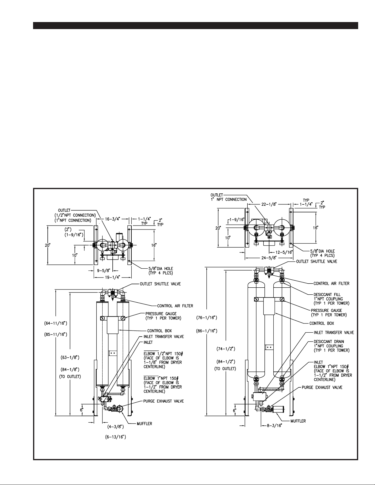
3.2 DIMENSIONS Models HLS-55 through HLS-150
HLS-55
HLS-80
HLS-55
HLS-80
HLS-55
HLS-80
HLS-55
HLS-80
HLS-120
HLS-150
HLS-120
HLS-55
HLS-150
HLS-80
HLS-55
HLS-80
HLS-55 & HLS-80
PRINTED IN THE U.S.A. PAGE 3
HLS-120 & HLS-150
* (ROTATED TO BACK ON HLS-150)

INSTALLING THE DRYER SECTION 4
4.1 LOCATION
WARNING
DO NOT INSTALL THIS DRYER IN AN ENVIRONMENT OF
CORROSIVE CHEMICALS, EXPLOSIVE GASSES, POISONOUS
GASSES, OR SATURATED STEAM HEAT.
Locate dryer in a protected, well vented area where ambient
temperatures are between 40oF and 120oF. If this dryer must be
installed where ambient temperatures are below 40
heat tracing must be properly installed on the inlet piping, purge exhaust
line and the desiccant towers to prevent freezing of the equipment.
Position the dryer in the upright position on a solid, level, vibration free
surface capable of supporting the dryer’s weight. Allow sufficient
clearance over and around the dryer. Refer to SECTION 3.2 for dryer
dimensions.
The dryer should not be located in extremely dirty areas where airborne
contaminants can accumulate on the dryer. If this cannot be prevented,
the dryer should be cleaned periodically.
o
F, insulation and
4.2 PIPING AND ANCILLARY EQUIPMENT
IMPORTANT
Make sure that the inlet air piping is connected to the bottom and the
outlet air piping is connected to the top of the dryer.
Make sure that the inlet and outlet piping to and from the dryer is
properly supported. Excessive stress may cause damage and/or
dryer malfunction.
Remove protective caps or covers from all valves before installing this
dryer.
If this dryer is to be installed into an existing piping system, clean the
existing inlet piping to remove all accumulated dirt, pipe scale, etc.,
before connecting the dryer. Make sure that the inlet and outlet shutoff
valves are tightly closed before connecting to the existing piping system.
When installing the piping and any additional components, make sure
that adequate pipe supports are used. Excessive stress on the dryer
and components may cause damage or premature failure. Use either
overhead or stiff-leg type supports.
Make sure that the piping is correctly connected to the dryer. The inlet
is the bottom connection and the outlet is the top connection.
Reference SECTION 3.2 for dryer dimensions and connection
locations.
Once the location has been determined, place the dryer into position.
Reference SECTION 1 for handling instructions.
4.2-1 BYPASS PIPING (optional)
The installation of bypass piping is not required, but will allow the
dryer and filter(s) to be taken off stream without interrupting the air
system.
In Figure 4A, a recommended bypass piping layout and additional
components are shown. Basic bypass piping should include an inlet
isolation valve, a bypass valve, and an outlet isolation valve. The
isolation and bypass valves must be bubble-tight.
4.2-2 FILTERS
A PROPERLY RATED COALESCING PREFILTER MUST BE
INSTALLED BEFORE THE DRYER TO REMOVE LUBRICATING
OILS, DUST AND PIPE SCALE CONTAMINATION. FAILURE TO
USE A PREFILTER WILL RESULT IN DAMAGE TO THE DRYER
AND VOIDS THE WARRANTY.
CAUTION
A coalescing prefilter must be installed before the dryer to remove
lubricating oils, dust and pipe scale contamination. It is
recommended that a high efficiency coalescing filter with an
automatic drain or electric drain valve be installed. The filter should
be equipped with a pressure differential indicator to monitor the
condition of the element.
A particulate afterfilter should be installed downstream of the dryer.
The afterfilter will remove any desiccant dust. The afterfilter should
be equipped with a pressure differential indicator to monitor the
condition of the element.
Make sure that the filters are properly installed according to the
instructions provided with them.
4.3 REMOTE PURGE EXHAUST PIPING
To reduce the noise during purging and tower depressurization, this
dryer was supplied with a muffler for installation on the purge exhaust
valve. If the sound or humidity discharged from this dryer is unacceptable, the purge of this dryer can be piped remotely away.
IMPORTANT
Make sure that the piping is as short as possible and does not
create back pressure on the dryer. To prevent liquid accumulation in the piping and purge valve, the piping must be at the
same level or lower than the purge valve.
The purge line must be vented to atmospheric pressure. If the
ambient temperature at the venting end of the piping is subject
to temperatures below 32oF, freeze protection must be installed.
The purge valve has threaded pipe connections. Reference Section
3.2 for location. Use adequate pipe supports on the piping to prevent
stress on the valve.
The distance will determine the size of piping that is recommended.
For distances of 10 feet or less, use piping of the same size as the
purge valve. For distances up to 20 feet, use piping one size larger
than the purge valve.
4.4 INSTALLING PRESSURE RELIEF VALVES
CAUTION
THESE VESSELS MUST BE PROTECTED BY PRESSURE RELIEF
VALVES. Refer to OSHA 1910.169 Par. b, Sub. Par (3) and ASME
Boiler and Pressure Vessel Code, Section VIII, Division 1, UG-1 25
through UG-136. Also check government regulations, i.e., state
and local codes.
Relief valve connection ports were NOT provided on this dryer. It is
recommended that relief valves be installed to comply with all
applicable codes. The relief valves should be full flow type, rated for
the dryer operating conditions. For recommended location see Figure
4A.
4.5 INSTALLING THE PURGE MUFFLER
To reduce the sound level during purge and tower depressurization,
this dryer was supplied with a muffler for installation on the purge
exhaust valve. For muffler location Reference SECTION 3.2.
The muffler was shipped separately. It should NOT be installed until
the dryer has been operated for several hours. From desiccant
installation, some dust may be present in the desiccant towers.
Operating the dryer with the muffler installed immediately after the
towers have been filled with desiccant or at initial start up may cause
the muffler to clog.
IMPORTANT
The dryer must be operated for several hours without the
muffler after the towers have been filled with desiccant. This
will prevent the muffler from becoming clogged.
Make sure that the elements are installed in all filter housings
prior to start up.
PAGE 4 PRINTED IN THE U.S.A.

INSTALLING THE DRYER SECTION 4
FIGURE 4A RECOMMENDED PIPING CONFIGURATION AND COMPONENTS
MODEL
HLS-55
HLS-80
HLS-120
HLS-150
DRYER
IN/OUT
1/2" NPT(F)
1" NPT(F)
1" NPT(F)
1" NPT(F)
F200-0055-1/2-C-AD
F200-0085-3/4-C-AD
F200-0150-1-C-AD
F200-0150-1-C-AD
PREFILTER
MODEL
IN/OUT
1/2" NPT(F)
3/4" NPT(F)
1" NPT(F)
1" NPT(F)
4.6 ELECTRICAL CONNECTIONS
SERIOUS PERSONAL INJURY AND DAMAGE TO THE DRYER
WILL OCCUR IF THE DRYER IS CONNECTED TO A POWER
SOURCE OTHER THAN THE VOLTAGE LISTED ON THE DATA
TAG.
WHEN INSTALLING THE ELECTRICAL CONNECTIONS FOR
THIS DRYER, COMPLY WITH NATIONAL ELECTRICAL CODE
AND ALL APPLICABLE FEDERAL, STATE AND LOCAL
CODES.
The power supply to the dryer will be connected into the dryer control
box. A 7/8" dia hole was provided in the bottom of the box for the
connection of conduit or a cord grip connector.
FIGURE 4B ELECTRICAL CONNECTIONS
WARNING
DEL-P
INDICATOR
MODEL
PD-6
PD-6
PD-6
PD-6
Check the electrical rating of the dryer as listed on the dryer data tag.
Make sure that the power source is correct for the dryer rating.
Remove the box cover to access the power supply and alarm
terminals. Wire the power supply as shown in Figure 4B. Connect
the wiring and necessary components to the dryer box. Comply with
all codes applicable for this installation.
AFTERFILTER
MODEL
F200-0055-1/2-RB-MD
F200-0085-3/4-RB-MD
F200-0150-1-RB-MD
F200-0150-1-RB-MD
INDICATOR
IN/OUT
1/2" NPT(F)
3/4" NPT(F)
1" NPT(F)
1" NPT(F)
DEL-P
MODEL
PD-6
PD-6
PD-6
PD-6
PRINTED IN THE U.S.A. PAGE 5

START UP SECTION 5
5.1 START UP
WARNING
BEFORE STARTING THIS DRYER, FOLLOW THE INSTALLATION
INSTRUCTIONS AND PROCEDURES COMPLETELY. SERIOUS
PERSONAL INJURY CAN RESULT IF INSTRUCTIONS ARE NOT
CAREFULLY AND COMPLETELY FOLLOWED.
DO NOT REMOVE, REPAIR, OR REPLACE ANY ITEM ON THIS
DRYER WHILE IT IS UNDER PRESSURE.
IMPORTANT
TO START THE DRYER YOU MUST PRESS THE RUN SWITCH
WHICH WILL LIGHT THE RUN LED.
If the dryer is being started up for the first time or after the
desiccant has been changed, the purge muffler must be removed.
Operate the dryer until no desiccant dust is visible at the purge
valve. Then the muffler can be reinstalled.
If bypass piping was installed on this dryer as outlined in SECTION
4.2, close the inlet and outlet isolation valves. Open the bypass valve.
Pressurize the air system. Once the air system is pressurized, slowly
open the inlet isolation valve. Check timing settings in control box.
The dryer should be factory set as shown in Figure 4B.
Energize the power supply to the dryer. Both towers will pressurize.
Several seconds later one tower will depressurize. Open the outlet
isolation valve.
5.2 PURGE FLOW ORIFICE
DRYER
MODEL
HLS-55
HLS-80
HLS-120
HLS-150
The Purge Orifice is located at the top of the outlet valve. Purge
can be adjusted by taking a blank orifice and drilling a new size
hole.
ORIFICE
SIZE
3/32" DIA
7/64" DIA
9/64" DIA
5/32" DIA
FLOW AT
100 PSIG
9.5 SCFM
12.9 SCFM
21.4 SCFM
26.4 SCFM
BLANK
ORIFICE P/N
26-1933
26-1933
26-1933
26-1933
5.3 CONDITIONING THE DESICCANT BED
To condition the desiccant bed, the dryer is operated withou t any
outlet flow, while the towers regenerate with purge air.
Close the outlet isolation valve and pressurize the system. Energize the
power supply and start the dryer. Observe the dryer for several cycles.
Make sure that it is operating properly.
At initial start up or after extended shutdowns (over one month), the dryer
may take 24 to 48 hours of continuous operation for the bed to be
conditioned. Moisture that has accumulated on the desiccant bed should
be removed before the dryer is placed on stream.
PRINCIPLE OF OPERATION SECTION 6
6.1 PRINCIPLE OF OPERATION
HLS Series Heatless Regenerative Air Dryers utilize the pressure swing
principle of operation. The desiccant bed in one tower dries the air stream
while the desiccant bed in the other tower is regenerated.
A purge of dry air is used for tower regeneration. It is taken from the outlet
of the dryer. To allow the correct amount of dry air to flow into the
regenerating tower, dryers are equipped with a purge metering orifice.
The heat created during adsorption of moisture in the drying tower is
retained in the desiccant bed and increases the moisture removal
capacity of the purge air.
When the dryer is pressurized and the power supply to the dryer is
energized, the dryer will begin operation. To achieve maximum
performance from this dryer, it should be operated continuously.
Operating this dryer for single shift periods may result in varied outlet
dew point performance.
The dryer operation consists of four stages; REPRESSURIZATION,
CHANGEOVER/DEPRESSURIZATION, DRYING and
REGENERATION.
The regeneration stage of one tower occurs at the same time as the
drying stage in the opposite tower. During the regeneration stage, a
percentage of dry air is directed through the desiccant bed of the
offstream tower. The purge air is vented through the purge valve to the
atmosphere.
FIGURE 6A PNEUMATIC SCHEMATIC
6.1-1 REPRESSURIZATION STAGE
Repessurization occurs in the regenerating tower. Repessurization
must occur before tower changover. This reduces shock to the
desiccant and the possibility of downstream pressure spikes.
The purge valve is closed and the purge air, which was vented to
atomosphere earlier in the cycle, is now used to repressurize the
regenerated tower.
6.1-2 CHANGEOVER/DEPRESSURIZATION STAGE
Tower changeover occurs after the previous regenerating tower is
pressurized. The controller signals the inlet transfer valve to switch.
The tower that was on line and drying the process air will begin to
depressurize.
6.1-3 DRYING AND REGENERATION STAGE
During the drying stage, one tower is pressurized with process air. This
tower is in the drying stage. The process air passes through the
desiccant bed, which adsorbs moisture from the air.
PAGE 6 PRINTED IN THE U.S.A.

USING THE DRYER SECTION 7
7.1 CONTROLLER
The Controller is a compact NEMA 4 control box. It has the following features:
• Dryer Status LEDs
- POWER ON LED - L/R TOWER DRYING LEDS
- RUN LED - L/R TOWER REGENERATING
LEDS
- HOLD LED - DRYER PURGING LED
- SWITCHING FAILURE LED
The Dryer Status LEDs are located on the front panel of the control box.
Figure 7A shows the location of each.
FIGURE 7A
When the Left tower is pressurized and on line drying the process air, the
corresponding LEFT TOWER DRYING LED is illuminated. When the right
tower is pressurized and on line drying the process air, the corresponding
RIGHT TOWER DRYING LED is illuminated.
The DRYER PURGING LED is illuminated when the purge exhaust valve
is energized open. During repressurization this LED will not be illuminated.
Repressurization occurs for approximately 20 seconds just before tower
changeover.
The operation sequence of the dryer is shown in FIGURE 7B TIMING
CHART.
SWITCHING FAILURE:
When there is a switching failure, the LED will be lit. This will energize
the contacts shown in FIGURE 4B. The contacts can be wired for
remote annunciation. To reset the Switching Failure Alarm press the
run button on the control box front panel.
HOLD FEATURE:
For low load or static pressure conditions, the hold contacts shown on
Figure 4B can be wired to an auxillary set of normally closed contacts
on the compressor starter. This will stop the cycling of the dryer and
repressurize both towers of the dryer, until there is demand on the
compressor. The Hold LED will light, if the dryer is wired as described
and the compressor is not running.
7.2 SETTING THE CYCLE TIME
Reference Figure 4B:
The setting for the time cycle is a 5 min/half cycle. For the half cycle
time setting, the switches indicated for DS1 (2, 5, 7, & 8) as shown in
the CYCLE TIME DETAIL have been factory set by pushing the
switches up. The values for these switches are (256, 32, 8, & 4) sec.,
so when added together equal 300 sec or 5 min. WE DO NOT
RECOMMEND a time cycle setting below 2 min/half cycle. For this
half cycle time setting, the switches that need to be pushed up are DS1
(4, 5, 6, & 7) there values are (64, 32, 16, & 8) sec. so when added
together equal 120 sec or 2 min.
The setting for the pressurization time is 20 sec. For the pressurization time setting, the switches indicated for DS2 (2 & 4) as shown in
the CYCLE TIME DETAIL have been factory set by pushing the
switches up. The values for these switches are (16 & 4) sec., so when
added together equal 20sec. WE DO NOT RECOMMEND CHANG-
ING THIS SETTING.
POWER ON
HOLD
STOP
RUN
RUN
SWITCHING FAILURE
TOWER DRYING
TOWER REGENERATING
LEFT
RIGHT
DRYER PURGING
The setting for the alarm time is 96 sec. For the alarm time setting,
the switches indicated for DS2 (5 & 6) as shown in the CYCLE TIME
DETAIL have been factory set by pushing the switches up. The values
for these switches are (64 & 32) sec., so when added together equal
96 sec. WE DO NOT RECOMMEND CHANGING THIS SETTING.
NOTE: THE ALARM TIME SETTING NEEDS TO BE LESS THEN
THE HALF CYCLE TIME SETTING OR THIS WILL NEGATE
THE ALARM FUNCTION.
Operating this dryer on the 4 minute cycle will more than
double the wear on the dryer components. To reduce wear on
the dryer, operate the dryer on the 10 minute cycle if the -40OF
dew point is acceptable.
IMPORTANT
FIGURE 7B CYCLE TIMING CHART
PRINTED IN THE U.S.A. PAGE 7

SHUTDOWN SECTION 8
8.1 SHUTDOWN PROCEDURES
Shutoff the air supply to the dryer. If bypass piping and valves were
installed, close the inlet and outlet isolation valves and open the
bypass valve. Let the dryer cycle until it is totally depressurized.
MAINTENANCE & TROUBLESHOOTING SECTION 9
9.1 DAILY INSPECTION
The following procedures should be performed daily:
• Check the dryer operating conditions, inlet temperature, ambient
temperature, inlet pressure and inlet flow.
• Monitor the dryer for one complete cycle. Make sure that it is
operating properly. Visually check the dryer and piping for damage.
• Check the purge muffler. Purge air should be exhausting from
the valve. If oil is present, the dryer and air system may be
contaminated with lubricants.
• Inspect all upstream equipment, aftercoolers, separators, drains
and filters. Make sure that all bypass valves are tightly closed.
• Check the prefilter(s) for proper draining. If the prefilter is not
equipped with an automatic drain, it must be manually drained.
Check the pressure differential indicator on all prefilters and
afterfilters. If the differential pressure is unacceptable, replace the
elements.
9.2 SCHEDULED MAINTENANCE
12 MONTHS
• Replace purge muffler element
• Replace the control air filter element
24-60 MONTHS
• The desiccant in the towers should be replaced every two to five
years. The life of the desiccant will vary depending on the inlet air
conditions. Systems with excessive contaminants and/or inadequate filtration will decrease the life span of the desiccant
drastically. Once the desiccant is contaminated with lubricants, it
must be replaced.
9.3 DESICCANT REPLACEMENT
WARNING
DO NOT ATTEMPT TO REMOVE ANY ITEM UNTIL ALL AIR
PRESSURE IS OUT OF THE VESSEL. CHECK ALL TOWER
PRESSURE GAUGES, MAKING SURE THAT THEY ARE AT 0
PSIG AND THAT INCOMING PRESSURE HAS BEEN TURNED
OFF.
ALWAYS WEAR EYE PROTECTION AND GLOVES WHEN
HANDLING THE DESICCANT. DUST FROM THE DESICCANT
MAY CAUSE EYE AND SKIN IRRITATION. AVOID BREATHING
THE DUST AND PROLONGED CONTACT WITH THE SKIN.
Remove any oil, dirt, or scale from the towers and piping. Do NOT
weld, grind or sandblast the vessels. The vessels may be steam
cleaned internally and externally to remove dirt and oil.
CAUTION
Make sure that the towers are clean to prevent contamination of
new desiccant.
Reinstall the bushing/diffusers in the bottom of the vessels. Install the
inlet piping assembly. Apply pipe thread sealant as necessary.
Remove the bushing/diffusers from the top of the vessels. Load
desiccant through these ports. REFER TO SECTION 3.1 FOR
PROPER DESICCANT AMOUNTS.
Reinstall the bushing/diffusers in the top of the vessels. Install the
outlet piping assembly. Reconnect the dryer to the process piping.
Apply pipe thread sealant as necessary.
Follow START UP PROCEDURES IN SECTION 5.1 to start up and place
dryer in operation.
For HLS-120 and HLS-150 fill and drain ports are provided, so piping
disassembly is not required.
9.4 CONTROL AIR FILTER REPLACEMENT
Close the dryer inlet and outlet isolation valves (and open bypass
valve if provided). Turn off the power and completely depressurize the
dryer.
WARNING
DO NOT REMOVE THE FILTER BOWL FROM HEAD UNTIL
HOUSING IS COMPLETELY DEPRESSURIZED.
After all pressure is out of the dryer, grasp the filter bowl firmly. While
pushing the bowl upward, turn it clockwise to remove it from the filter
head.
Unthread the used element from the head. Discard the used element
properly.
FIRST AID IN CASE OF EYE CONTACT, IMMEDIATELY FLUSH
EYES WITH PLENTY OF WATER FOR AT LEAST 15 MINUTES.
CONSULT A PHYSICIAN.
Take dryer off stream following the SHUTDOWN PROCEDURES IN
SECTION 8.
For HLS-55 and HLS-80:
Carefully disconnect the inlet and outlet piping assemblies from the
dryer and process piping. Disconnect the piping assemblies at the
union connections. Unthread the bushing/diffusers from the bottom of
each vessel to drain the old desiccant.
PAGE 8 PRINTED IN THE U.S.A.
Remove new element from the shipping package. Thread the new
element into the filter head.
Position the bowl in the filter head. While pushing the bowl upward
into the head, turn the bowl counterclockwise to lock it in place.
Following the start up procedures for the dryer, place the dryer on
stream.

MAINTENANCE & TROUBLESHOOTING SECTION 9
9.5 TROUBLESHOOTING
The following check list should be used as a guideline for troubleshooting problems.
IS THE POWER ON AND RUN SWITCH PRESSED?
Check the main power source and check that the Power LED is
lit. Make sure that the dryer Run switch has been pressed and
that the Run LED is lit
IS THE SYSTEM PRESSURIZED?
The dryer is designed to operate at 60 to 150 psig. Check the
upstream equipment and any isolation or bypass valves.
IS THE DRYER CYCLING?
• IS THE CONTROL SYSTEM WORKING?
Is there incoming power to the control box.
• IS THERE CONTROL AIR PRESSURE, 60 PSIG MINIMUM.
Make sure that the dryer inlet pressure is above 60 PSIG. Check
the control air filter element and replace it with a new element.
Reference Section 9.4 for element replacement instructions.
• IS THE INLET VALVE FAULTY?
Rebuild or replace the inlet valve as necessary. Use manual
override to check.
• IS THE PURGE EXHAUST VALVE FAULTY?
Rebuild or replace the faulty purge exhaust valve. Use manual
override to check.
• IS THE OUTLET VALVE FAULTY?
Check the outlet shuttle valve.
ARE THE TOWERS DEPRESSURIZING?
Check the purge valve for proper operation. Check the purge
muffler. It might be clogged. If clogged or damaged, replace it.
Use manual overide to check. (This should cause
depressurization.)
IS THE DEW POINT ACCEPTABLE?
• ARE THE INLET CONDITIONS WITHIN THE SPECIFICATIONS?
Reference Section 3.1 for the inlet conditions of the dryer.
Correct the inlet conditions if necessary. Excessive inlet flow will
greatly reduce the performance of the dryer.
• WAS THE DESICCANT INSTALLED?
Make sure that the desiccant was installed. Reference Section 9.3
for desiccant installation procedures.
• IS THE DESICCANT CONTAMINATED WITH LUBRICANTS?
Check the condition of the desiccant bed. If the bed is
contaminated with lubricants, replace the desiccant following the
procedures in Section 9.3.
• IS THE DESICCANT CONTAMINATED WITH MOISTURE?
If the dryer was operated under excessive inlet conditions, the
desiccant bed may be saturated with liquid moisture. Check
upstream equipment such as aftercoolers. Check the actual inlet
conditions, correct them and condition the bed following the
procedures in Section 5.3.
• ARE THE BYPASS VALVES OPEN OR LEAKING?
Check the valves (if installed). Repair or replace if faulty.
9.6 WIRING DIAGRAMS
THE DRYER CONTROL CIRCUIT IS DUAL VOLTAGE RATED.
NEVER SET THE BOARD TO A VOLTAGE OTHER THAN THE
VOLTAGE RATING OF THE DRYER LISTED ON THE DRYER
DATA TAG. SETTING THE BOARD INCORRECTLY WILL CAUSE
DAMAGE TO THE INLET AND PURGE VALVES AND POSSIBLE
PERSONAL INJURY OR FIRE.
PRINTED IN THE U.S.A. PAGE 9
CAUTION

REPLACEMENT PARTS SECTION 10
ITEM
1
Inlet Transfer Valve, 4-way
a
Repair kit for 4-way valve
b
Valve pilot for 4-way valve
c
4-way valve without base
2
Outlet Shuttle Valve
3
Purge Valve, 3-way
a
Repair Kit for 3-way valve
b
Valve pilot for 3-way valve
4
Pressure Gauge
5
Diffuser/Desiccant Retainer
6
Purge Exhaust Muffler
a
Element, purge exhaust muffler
7
Control Air Filter
a
Element, control air filter
8
Desiccant
Activated Alumina, 1/8" dia, 25# pail
9
Control Box (complete)
a
Circuit Board only
b
Membrane Panel
c
Pressure Switch
DESCRIPTION
HLS-55
(115V)
PART NO.
14-2072
26-6516
26-6518
26-6520
14-2071
14-2076
26-6514
26-6517
29-0344
26-6464
26-6152
26-6251
26-6830
26-6831
33-0237
46-2771
26-6469
26-6356
26-5284
QTY
HLS-55
(230V)
PART NO.
1
14-2073
1
26-6516
1
26-6518
1
26-6522
1
14-2071
1
14-2077
1
26-6514
1
26-6517
2
29-0344
4
26-6464
1
26-6152
1
26-6251
1
26-6830
1
26-6831
3
33-0237
1
46-2771
1
26-6469
1
26-6356
2
26-5284
QTY
1
1
1
1
1
1
1
1
2
4
1
1
1
1
3
1
1
1
2
HLS-80
(115V)
PART NO.
14-2074
26-6515
26-6518
26-6521
14-2071
14-2078
26-6514
26-6517
29-0344
26-6464
26-3734
26-6539
26-6830
26-6831
33-0237
46-2771
26-6469
26-6356
26-5284
QTY
1
1
1
1
1
1
1
1
2
4
1
1
1
1
4
1
1
1
2
HLS-80
(230V)
PART NO.
14-2075
26-6515
26-6518
26-6523
14-2071
14-2079
26-6514
26-6517
29-0344
26-6464
26-3734
26-6539
26-6830
26-6831
33-0237
46-2771
26-6469
26-6356
26-5284
QTY
1
1
1
1
1
1
1
1
2
4
1
1
1
1
4
1
1
1
2
PAGE 10 PRINTED IN THE U.S.A.

REPLACEMENT PARTS SECTION 10
ITEM
1
Inlet Transfer Valve, 4-way
a
Repair kit for 4-way valve
b
Valve pilot for 4-way valve
c
4-way valve without base
2
Outlet Shuttle Valve
3
Purge Valve, 3-way
a
Repair Kit for 3-way valve
b
Valve pilot for 3-way valve
4
Pressure Gauge
5
Diffuser/Desiccant Retainer
6
Purge Exhaust Muffler
a
Element, purge exhaust muffler
7
Control Air Filter
a
Element, control air filter
8
Desiccant
Activated Alumina, 1/8" dia, 25# pail
9
Control Box (complete)
a
Circuit Board only
b
Membrane Panel
c
Pressure Switch
DESCRIPTION
HLS-120
(115V)
PART NO.
14-2074
26-6515
26-6518
26-6521
14-2071
14-2078
26-6514
26-6517
29-0344
26-6464
26-3734
26-6539
26-6830
26-6831
33-0237
46-2771
26-6469
26-6356
26-5284
QTY
HLS-120
(230V)
PART NO.
1
14-2075
1
26-6515
1
26-6518
1
26-6523
1
14-2071
1
14-2079
1
26-6514
1
26-6517
2
29-0344
4
26-6464
1
26-3734
1
26-6539
1
26-6830
1
26-6831
6
33-0237
1
46-2771
1
26-6469
1
26-6356
2
26-5284
QTY
1
1
1
1
1
1
1
1
2
4
1
1
1
1
6
1
1
1
2
HLS-150
(115V)
PART NO.
14-2074
26-6515
26-6518
26-6521
14-2071
14-2080
26-6250
26-6519
29-0344
26-6464
26-3262
26-5774
26-6830
26-6831
33-0237
46-2771
26-6469
26-6356
26-5284
QTY
1
1
1
1
1
1
1
1
2
4
1
1
1
1
7
1
1
1
2
HLS-150
(230V)
PART NO.
14-2075
26-6515
26-6518
26-6523
14-2071
14-2081
26-6250
26-6519
29-0344
26-6464
26-3262
26-5774
26-6830
26-6831
33-0237
46-2771
26-6469
26-6356
26-5284
QTY
1
1
1
1
1
1
1
1
2
4
1
1
1
1
7
1
1
1
2
PRINTED IN THE U.S.A. PAGE 11

Safety is everybody•s business and is based on your use of good common sense. All situations or circumstances cannot
SAFETY PRECAUTIONS
always be predicted and covered by established rules. Therefore, use your past experience, watch out for safety hazards
and be cautious.
DANGER
DISCHARGE AIR USED FOR
BREATHING WILL CAUSE SEVERE
INJURY OR DEATH. CONSULT
FILTRATION SPECIALIST FOR
ADDITIONAL FILTRATIONS AND
TREATMENT EQUIPMENT TO
MEET HEALTH AND SAFETY
REGULATIONS.
DANGER
AIR AND OIL UNDER PRESSURE
WILL CAUSE SEVERE
PERSONAL INJURY OR DEATH.
SHUT DOWN COMPRESSOR AND
RELIEVE SYSTEM OF ALL
PRESSURE BEFORE REMOVING
VALVES, CAPS, PLUGS,
FITTINGS, BOLTS AND FILTER.
WARNING
ELECTRICAL SHOCK FROM
IMPROPER GROUNDING CAN
CAUSE INJURY OR DEATH.
GROUND UNIT AND RELATED
EQUIPMENT ACCORDING TO
NATIONAL ELECTRICAL CODE
AND LOCAL REGULATIONS.
WARNING
READ THE OPERATOR•S
MANUAL BEFORE STARTING
THIS UNIT. FAILURE TO ADHERE
TO INSTRUCTIONS CAN RESULT
IN SEVERE PERSONAL INJURY
OR DEATH. REPLACEMENT
MANUALS CAN BE
PURCHASHED BY CONTACTING
THE MANUFACTURER.
PAGE 12 PRINTED IN THE U.S.A.
 Loading...