

Van Air Systems High Dew Point Alarm Box User Manual
INSTALLATION, OPERATION & MAINTENANCE INSTRUCTIONS
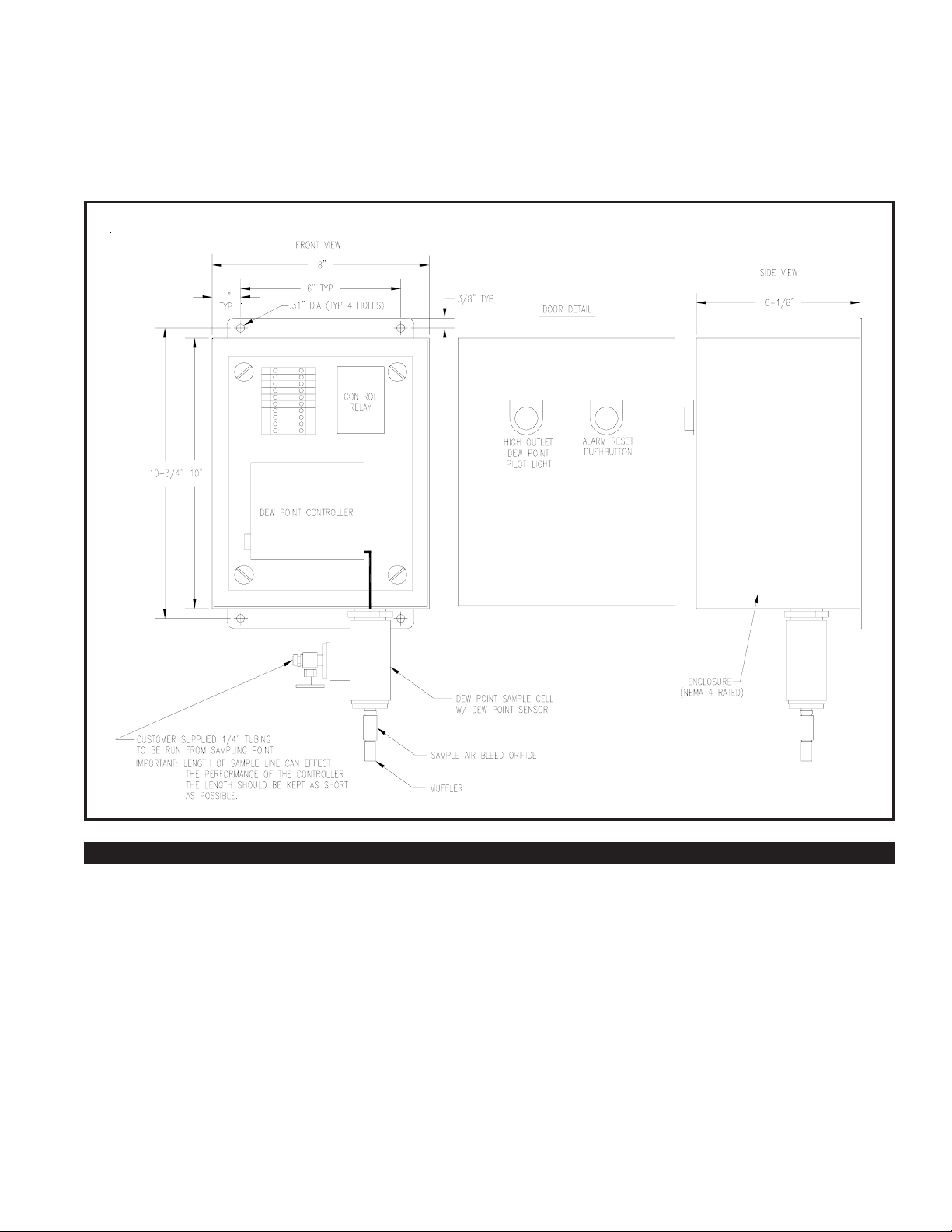
FIGURE 2A DIMENSIONS
FEBRUARY 2006
32-0283
FOR
HIGH DEW POINT ALARM BOX
P/N 46-2064
SPECIFICATIONS AND DIMENSIONS SECTION 1
WEIGHT ................ 25 LBS
DIMENSIONS........ see Figure 2A
MOUNTING .......... see Figure 2A
ENCLOSURE
• Enamel painted Steel Enclosure
• Nema 4 Rated
• Continuous Hinged
DEW POINT CONTROLLER (humistat)
RANGE OF CONTROL ................... 4% to 98% Relative Humidity
(NOTE: Set plug and sensor determine actual operating range)
INPUT POWER ................................. 115V-1PH-56/60Hz
OUTPUT MODE ............................... SPDT. relay, 1 amperes,
noninductive maximum
DEW POINT SENSOR (hygrosensor)
RANGE OF CONTROL ................... 1.4% to 6% RH @ 80oF
TYPE ................................................. DUNMORE-TYPE lithium
chloride element.
SET POINT PLUG
SET POINT ....................................... approx. 0OF Dew point @ 80oF
DEW POINT SAMPLE CELL
• Sample line isolation needle valve
• Sample cell bleed orifice fitting
MAXIMUM SAMPLE AIR PRESSURE ............. 150 PSIG
SAMPLE LINE CONNECTION SIZE ............... 1/4" tube fitting
ALARM OUTPUT CONTACT
ELECTRICAL RATING .................... 115V-1PH-60Hz, 10 ampere
OUTPUT MODE ............................... Normally open contact,
latching (push-button must be pressed to reset)
LIGHT & RESET PUSH-BUTTON
• High Dew Point Light (red)
• Alarm Reset Push-button
PAGE 1
SAFETY SECTION 2
2.1 HANDLING
DO NOT DROP THE UNIT.
DO NOT LIFT ALARM BOX BY THE SAMPLE CELL
2.2 INSTALLATION
BEFORE STARTING INSTALLATION PROCEDURES, TURN OFF
POWER AND DEPRESSURIZE THE PIPING WHERE SAMPLE LINE
IS TO BE INSTALLED, TO PREVENT INJURY. SERIOUS PERSONAL
INJURY MAY RESULT IF THIS SAFETY RULE IS NOT FOLLOWED.
WHEN INSTALLING AND OPERATING THIS EQUIPMENT, COMPLY
WITH THE NATIONAL ELECTRICAL CODE AND ALL APPLICABLE
FEDERAL, STATE, AND LOCAL CODES.
WHEN INSTALLING THIS ALARM BOX, MAKE SURE THAT THE
NEMA RATING IS APPLICABLE TO THE INSTALLATION.
MAKE SURE THAT ALL CUSTOMER SUPPLIED WIRING AND
ELECTRICAL DEVICES ARE PROPERLY SIZED TO HANDLE THE
ELECTRICAL REQUIREMENTS OF THE UNIT.
2.3 OPERATION
USE THIS DEVICE FOR COMPRESSED AIR ONLY.
2.4 MAINTENANCE
DO NOT REMOVE, REPAIR, OR REPLACE ANY ITEM ON THE
SAMPLE UNIT WHILE IT IS PRESSURIZED.
TURN OFF MAIN POWER TO THE CONTROL BEFORE
STARTING MAINTENANCE PROCEDURES.
INSTALLATION SECTION 3
3.1 INST ALLING THE UNIT
Mount the enclosure on a flat stable surface, where the alarm light
can be easily seen. The unit should be installed as close as
possible to the sample point. Allow enough space to open door and
to connect the sample line. Reference FIGURE 2A for mounting
hole dimensions.
3.2 INST ALLING THE DEW POINT SAMPLE LINE
A 1/4" sample line must be connected to the isolation needle valve
on the sample cell.
CAUTION
LENGTH OF SAMPLE LINE CAN EFFECT THE PERFORMANCE
OF THE CONTROLLER. THE LENGTH SHOULD BE KEPT AS
SHORT AS POSSIBLE
The sample source should be less than 150 PSIG. Do not use a
pressure regulating device between the source and the sample cell.
The sample source should be free of contaminants and high
temperatures (over 100oF).
Use copper or stainless steel tubing for the sample line. DO NOT
USE PLASTIC TUBING.
DO NOT CONNECT SAMPLE LINE TO A SOURCE EXCEEDING
150 PSIG.
DO NOT CONNECT SAMPLE LINE TO A SOURCE CONTAINING
CONTAMINANTS AND/OR HIGH TEMPERATURES.
3.3 ELECTRICAL CONNECTIONS
WHEN INSTALLING AND OPERATING THIS EQUIPMENT,
COMPLY WITH THE NATIONAL ELECTRICAL CODE AND ALL
APPLICABLE FEDERAL, STATE, AND LOCAL CODES.
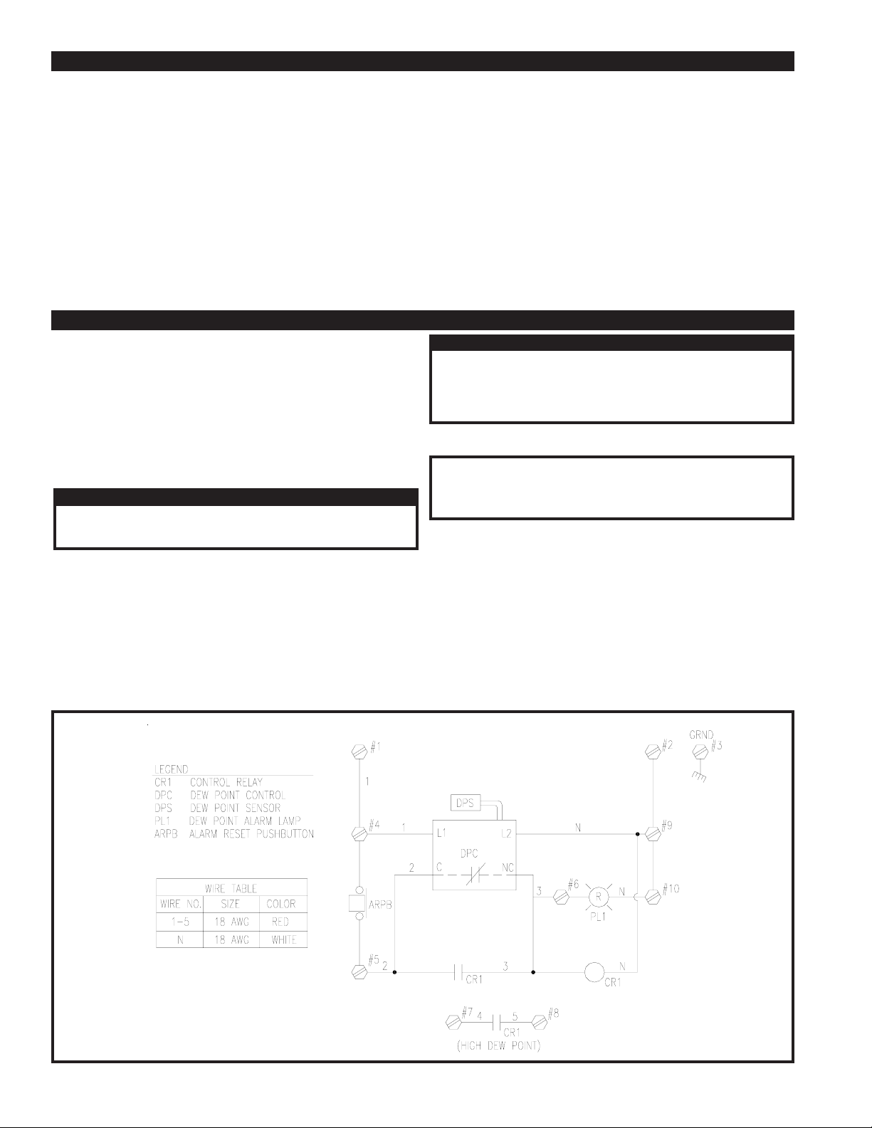
3.3-1 POWER SUPPLY
The unit requires a power source of 115V-1PH-60Hz for
operation. Make the necessary electrical connections from the
power source to the unit. Reference FIGURE 3A, Wiring Diagram.
3.3-2 ALARM OUTPUT CONTACT
The alarm output contact is labeled as terminals numbered 7 & 8
inside the enclosure. The contacts can be used to activate a
device in the event of an alarm condition.
If the alarm output contacts are to be used, make the necessary
wiring connections from the alarm enclosure terminal strip to the
remote device.
CAUTION
IMPORTANT
FIGURE 3A WIRING DIAGRAM
PAGE 2
 Loading...