

OCTOBER 2012
2950 Mechanic Street
Lake City, PA 16423 USA
Phone: 800-840-9906
Fax: 814-774-3482
www.vanairsystems.com
INSTALLATION, OPERATION & MAINTENANCE MANUAL
FOR
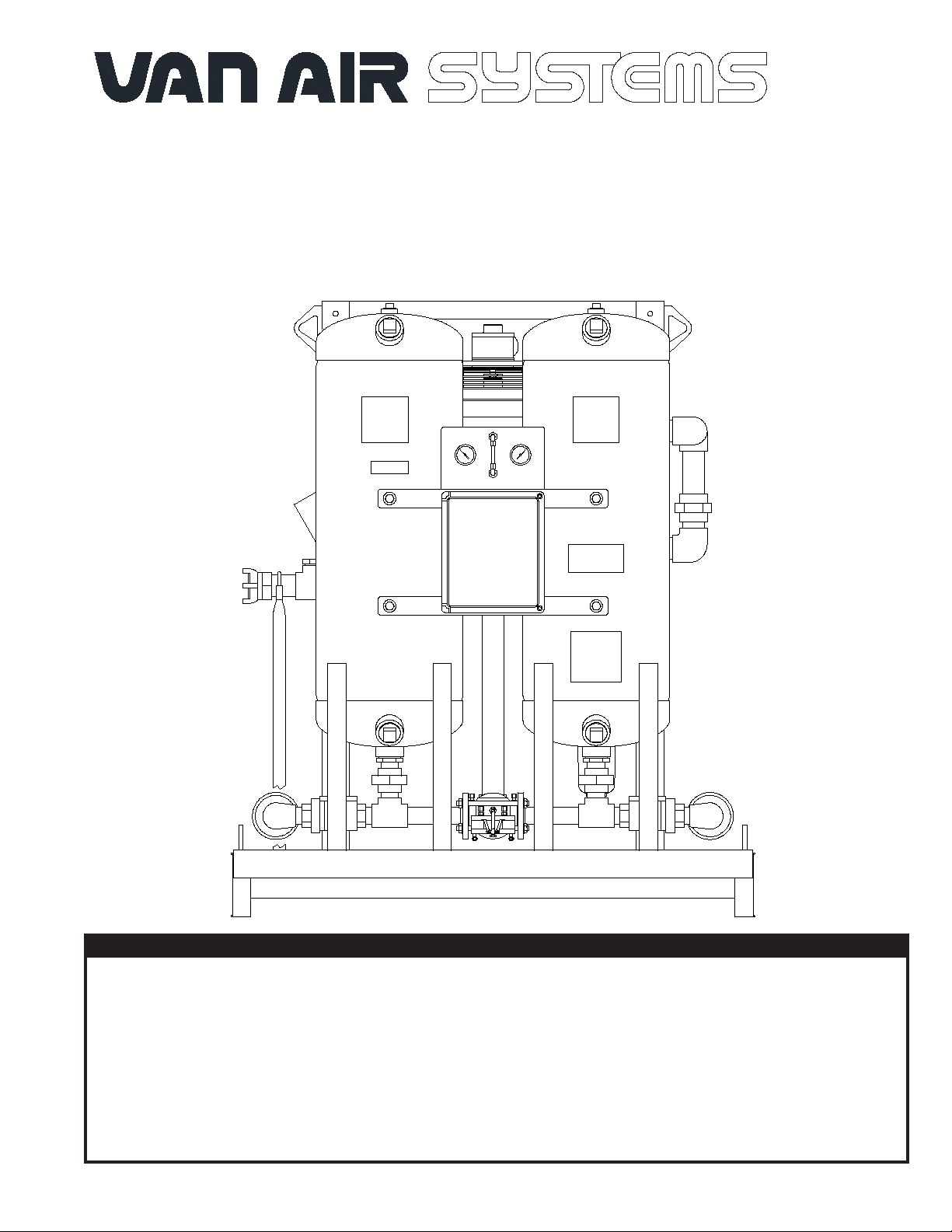
PREP-40 PORTABLE COMPRESSED AIR DRYER SYSTEM
model
FR-400 (P/N 81-2441)
REV A
WARNING
READ ALL INFORMATION IN THIS MANUAL BEFORE INSTALLATING OR OPERATING THE DRYER SYSTEM.
BEFORE STARTING MAINTENANCE PROCEDURES, TURN OFF THE MAIN POWER TO THE DRYER SYSTEM
AND COMPLETELY DEPRESSURIZE THE UNIT TO PREVENT PERSONAL INJURY.
DO NOT REMOVE, REPAIR, OR REPLACE ANY ITEM ON THIS DRYER SYSTEM WHILE IT IS PRESSURIZED.
NEVER OPERATE THIS DRYER SYSTEM ABOVE THE RATED OPERATING CONDITIONS. OPERATION
ABOVE SPECIFIED CONDITIONS WILL RESULT IN DECREASED PERFORMANCE, POSSIBLE DAMAGE TO
THE UNIT AND/OR PERSONAL INJURY.
PAGE 1

HANDLING SECTION 1
1.1 HANDLING INSTRUCTIONS
DO NOT LIFT THE DRYER SYSTEM BY PIPING OR CONTROL BOX
WARNING
SUPPORT BARS. THESE COMPONENTS ARE NOT DESIGNED TO
HOLD THE WEIGHT OF THE DRYER. PERSONAL INJURY AND/OR
EQUIPMENT DAMAGE MAY RESULT.
Lift the dryer system by the lifting lugs on both vessels in combination with
the lifting lugs on the pre-cooler supports, or by the base using a fork lift
truck.
If the unit is to be lifted by an overhead device, attach the lifting chains or
cables to the vessel lifting lugs and the lifting lugs on the pre-cooler
supports. Make sure that the chains or cables are clear of all piping and
dryer components.
If outside storage is required, the unit MUST BE adequately covered
to prevent rain or snow from accumulating on the dryer system. The
unit must be placed on a paved surface to keep it out of standing
water and mud.
1.3 EQUIPMENT CHECK
Inspect the dryer system for any damage that may have occurred
during shipment. Inspect all ttings, piping connections, fasteners,
etc. for loose connections. Also check gauges and lights for cracks
or breakage.
IF DRYER SYSTEM WAS DAMAGED DURING SHIPMENT:
(1) NOTIFY CARRIER IMMEDIATELY AND FILE A CLAIM.
(2) CONSULT FACTORY BEFORE OPERATING THE DRYER
SYSTEM.
1.2 STORAGE INSTRUCTIONS
If the unit is to be placed in storage before it is installed, it should be stored
indoors and covered with a tarpaulin to keep it clean. The location should
be free from corrosive gasses and extreme humidity, which can cause
damage to the unit.
SAFETY SECTION 2
2.1 HANDLING
DO NOT LIFT THE DRYER SYSTEM BY PIPING OR CONTROL BOX
SUPPORT BARS. THESE COMPONENTS ARE NOT DESIGNED TO
HOLD THE WEIGHT OF THE DRYER SYSTEM. PERSONAL INJURY
AND/OR EQUIPMENT DAMAGE MAY RESULT.
LIFT THE DRYER SYSTEM BY THE LIFTING LUGS ON BOTH
VESSELS IN COMBINATION WITH THE LIFTING LUGS ON THE
PRE-COOLER SUPPORTS, OR BY THE BASE USING A FORK LIFT
TRUCK.
MAKE SURE THAT ALL LIFTING EQUIPMENT IS CAPABLE OF
SUPPORTING THE WEIGHT OF THE DRYER SYSTEM.
DURING NORMAL OPERATION, THE INLET PIPING MAY REACH
TEMPEREATURES OF 150°F. CONTACT WITH THE PIPING MAY
RESULT IN SERIOUS PERSONAL INJURY.
DO NOT OPERATE THIS DRYER SYSTEM ABOVE THE MAXIMUM
RATED WORKING PRESSURE.
OPERATING CONDITIONS FOR PROPER PERFORMANCE OF THIS
DRYER SYSTEM ARE DIFFERENT THAN MAXIMUM OPERATING
CONDITIONS FOR THE VESSELS. BE SURE TO CHECK THE
DRYER SYSTEM OPERATING CONDITIONS. SEE SECTION 3.1.
USE THIS DRYER SYSTEM FOR COMPRESSED AIR ONLY.
2.2 INSTALLATION
THESE ASME CODE VESSELS MUST BE PROTECTED BY
PRESSURE RELIEF VALVES. Refer to OSHA 1910.169 Par. b, Sub.
Par (3) and ASME Boiler and Pressure Vessel Code, Section VIII,
Division 1, UG-125 through UG-136. Also comply with all state and
local codes.
WHEN INSTALLING AND OPERATING THIS EQUIPMENT, COMPLY
WITH THE NATIONAL ELECTRICAL CODE AND ALL APPLICABLE
FEDERAL, STATE, AND LOCAL CODES.
ALWAYS WEAR EYE PROTECTION, GLOVES AND A RESPIRATORY
PROTECTIVE DEVICE WHEN HANDLING THE DESICCANT.
DESICCANT DUST MAY CAUSE EYE AND SKIN IRRITATION. AVOID
BREATHING THE DUST AND PROLONGED CONTACT WITH THE SKIN.
FIRST AID IN CASE OF EYE CONTACT WITH DESICCANT DUST;
IMMEDIATELY FLUSH THE EYES WITH PLENTY OF WATER FOR AT
LEAST 15 MINUTES. CONSULT A PHYSICIAN.
2.3 OPERATION
DO NOT OPERATE DRYER SYSTEM IF EITHER VESSEL IS LEAKING.
IMMEDIATELY TAKE THE DRYER SYSTEM OUT OF SERVICE.
DO NOT OPERATE DRYER SYSTEM IF THE AFTERCOOLER CORE,
OR OTHER COMPONENTS ARE LEAKING. IMMEDIATELY TAKE THE
DRYER SYSTEM OUT OF SERVICE AND FIX OR REPLACE THE
LEAKING COMPONENT.
ANY DAMAGE TO THE VESSELS CAN MAKE THEM UNSAFE TO
USE. INSPECT OUTSIDE AND INSIDE OF VESSELS REGULARLY
FOR CORROSION AND ANY DAMAGE (I.E., DENTS, GOUGES OR
BULGES). IF DAMAGED, TAKE OUT OF SERVICE IMMEDIATELY.
AIR FROM THIS DRYER SYSTEM IS NOT SUITABLE FOR
BREATHABLE AIR SYSTEMS WITHOUT FURTHER TREATMENT.
DO NOT OPERATE THIS DRYER SYSTEM IF EITHER VESSEL
HAS BEEN DAMAGED BY FIRE. TAKE OUT OF SERVICE
IMMEDIATELY AND NOTIFY YOUR CERTIFYING AUTHORITY.
FILTER AND SEPARATOR DISCHARGE MAY CONTAIN
COMPRESSOR LUBRICANTS. COMPLY WITH ALL
REGULATIONS CONCERNING THEIR DISPOSAL.
2.4 MAINTENANCE
DO NOT REMOVE, REPAIR, OR REPLACE ANY ITEM ON THE
DRYER SYSTEM WHILE IT IS PRESSURIZED. TURN OFF MAIN
POWER TO THE DRYER SYSTEM AND DEPRESSURIZE THE
DRYER SYSTEM COMPLETELY BEFORE STARTING
MAINTENANCE PROCEDURES.
DO NOT WELD OR GRIND EITHER VESSEL. IT WILL NOT BE
SAFE TO OPERATE. (Note: Any uncertied alteration to the
vessels VOIDS the ASME Code Certication and the Warranty.)
NEVER REMOVE THE FAN GUARD WHILE THE AFTERCOOLER
IS OPERATING. CONTACT WITH THE ROTATING FAN BLADES
MAY RESULT IN SERIOUS PERSONAL INJURY.
PAGE 2

SPECIFICATIONS SECTION 3
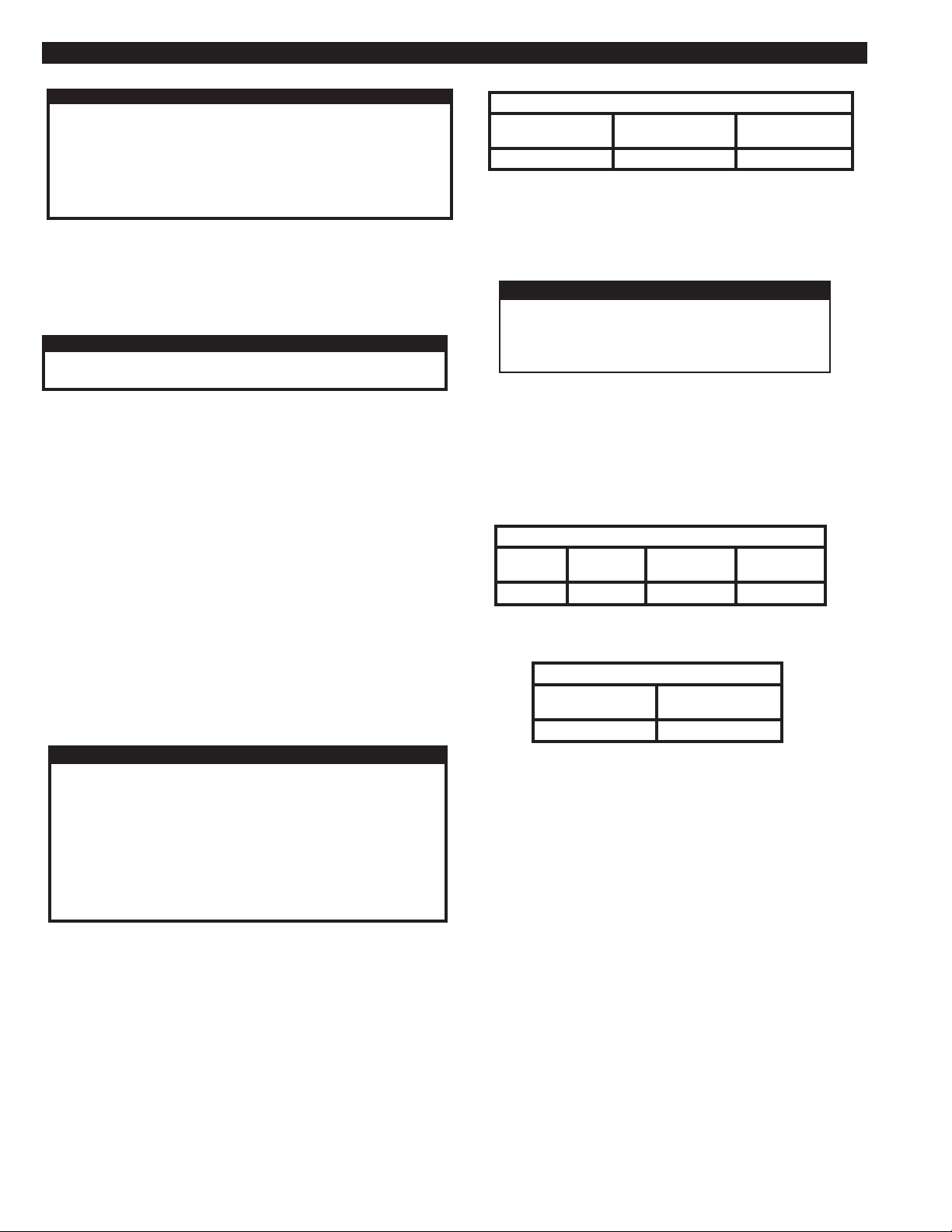
3.1 SPECIFICATIONS
WEIGHT.............................. 1790 lbs (with desiccant installed)
DIMENSIONS...... ............... See SECTIONS 3.2
IN/OUT CONNECTION...... 2" 4-lug coupling (Dixon #AM28)
VESSELS (desiccant towers)
Construction ................... Manufactured to the ASME CODE, Section VIII, Division 1.
Vessels stamped "U" symbol.
Design Pressure ............. 175 PSIG
Design Temperature ....... -20OF TO 300OF
PIPING
Threaded ttings: ........... ASME B16.3
Threaded unions: .......... ASME B16.39
Flanges: ......................... ASME B16.5
Pipe: .............................. Carbon steel, Schedule 40
VALVES
Inlet ............................... Proprietary 3-Way piloted shuttle valve
Outlet .............................. Two (2) Check valves, buttery type
Purge .............................. Normally closed, air operated type
CONTROL AIR FILTER
Construction ................... Aluminum housing
PREFILTER/AFTERFILTER
Construction ................... Aluminum housing
PRE-COOLER
Core. ............... ................Aluminum
Fan..................................Polypropylene blades with Aluminum hub
Fan Guard ......................Steel
SEPARATOR/PREFILTER
Construction ................... Aluminum housing
ELECTRICAL
Standard 115 Volt ........... 115-120V/1PH/50-60Hz
DESICCANT
Material ........................... Activated Alumina, 1/8" (2-5 MM) Bead type
Quantity Per Tower..........215 LBS
OPERATING CONDITIONS
Inlet Air Pressure ............................ MAX 175 PSIG
Inlet Air Temperature ...................... MAX 150OF
Ambient Air Temperature................ MIN 40OF..........MAX 120OF
SYSTEM RATED INLET CONDITIONS
Inlet Air Pressure ............................ 100 PSIG
Inlet Air Temperature ...................... 150OF (based on 85°F ambient and 15°F approach from the pre-cooler)
Relative Humidity (saturation) ........ 100% RH
DRYER FLOW CAPACITIES (SCFM) at various pressures (1000F)
60 PSIG 80 PSIG 100 PSIG 110 PSIG 125 PSIG 140 PSIG 150 PSIG 160 PSIG 175 PSIG
FR-400 260 330 400 417 441 465 479 494 514
PAGE 3
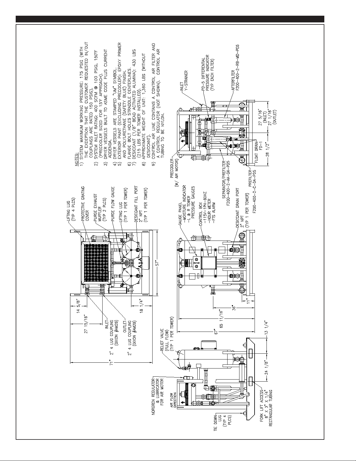
SPECIFICATIONS SECTION 3
3.2 DIMENSIONS
PAGE 4

INSTALLATION SECTION 4
4.1 LOCATION
WARNING
DO NOT INSTALL THIS DRYER SYSTEM IN AN ENVIRONMENT
OF CORROSIVE CHEMICALS, EXPLOSIVE GASSES, POISONOUS
GASSES, OR SATURATED STEAM HEAT.
Locate dryer system in a protected, well vented area where ambient
temperatures are between 40oF and 120oF. Allow sufcient clearance
over and around the dryer system for access to desiccant ll and drain
ports and controls. Refer to SECTION 3.2 for dryer dimensions.
If this dryer system must be installed where ambient temperatures are
below 40oF, insulation and heat tracing must be properly installed on
the inlet piping, separator, prelter, purge exhaust line and the
desiccant towers to prevent freezing of the equipment.
Position the dryer system in the upright position on a solid, level,
vibration free surface capable of supporting the dryer system’s weight.
Refer to SECTION 3.1 for dryer system specications.
The dryer system should not be located in extremely dirty areas where
airborne contaminants can accumulate on the dryer system. If this
cannot be prevented, the dryer system should be cleaned periodically.
An accumulation of dirt on the precooler will greatly reduce its
efciency. Accumulated dirt may also cause the inlet transfer valve to
fail.
4.2 DESICCANT INSTALLATION
The desiccant was factory installed in both towers before the dryer
shipped.
4.3 ELECTRICAL CONNECTIONS
SERIOUS PERSONAL INJURY AND DAMAGE TO THE
DRYER SYSTEM WILL OCCUR IF THE DRYER SYSTEM IS
CONNECTED TO A POWER SOURCE OTHER THAN THE
VOLTAGE LISTED ON THE DATA TAG.
Connect the dryer system power cord to a 115V/1PH/60Hz power
source capable of supplying a minimum of 2 AMPS.
WARNING
4.4 INSTALLING THE PURGE MUFFLERS
Purge mufers were shipped separately. They should NOT be installed
until the dryer system has been operated for several hours. From
desiccant installation, some dust may be present in the desiccant
towers. Operating the dryer system with the mufers installed immediately after the towers have been lled with the desiccant or during
initial start up may cause the mufers to clog. See SECTION 5.6 for
purge mufer installation.
4.5 FILL LUBRICATOR WITH OIL
The lubricator is located in the air line between the regulator and the
pre-cooler air motor. Fill the lubricator with Pneumatic Lubricating Oil
SAE10 AD220 (Van Air p/n 26-7032 quart).
4.6 CONNECT DRAIN LINES
Connect the automatic drains for the separator/prelter and the prelter
to an appropriate collection container. Filter and separator/prelter
discharge may contain compressor lubricants. Comply with all regulations concerning their disposal.
4.7 CONNECTING THE INLET AND OUTLET
The inlet and outlet of this dryer system are equipped with 2" 4-lug
couplings. Connect the inlet and outlet air hoses to the dryer system.
Remember to use SAFETY CLIPS.
PAGE 5
START UP SECTION 5
5.1 START UP
WARNING
BEFORE STARTING THIS DRYER SYSTEM, FOLLOW THE
INSTALLATION INSTRUCTIONS AND PROCEDURES COMPLETELY.
SERIOUS PERSONAL INJURY CAN RESULT IF INSTRUCTIONS ARE
NOT CAREFULLY AND COMPLETELY FOLLOWED.
DO NOT REMOVE, REPAIR, OR REPLACE ANY ITEM ON THIS
DRYER SYSTEM WHILE IT IS PRESSURIZED.
Make sure that the Power switch is in the OFF position.
If the dryer system is being started up for the rst time or after the
desiccant has been changed, the purge mufers must be removed.
See SECTION 2.2 for safety precautions concerning the desiccant
dust.
WARNING
WHEN OPERATING THIS DRYER SYSTEM WITHOUT THE
MUFFLERS INSTALLED, USE HEARING PROTECTION.
Pressurize the air system.
Place the Power switch in the ON position. One tower will already be
pressurized. The other tower will depressurize. The purge valve on
the tower that is not pressurized will be open, air should be exhausting
from the mufer.
The dryer system is equipped with a purge metering valve. The setting
should be checked per SECTION 5.2 before placing the dryer system
on stream.
Set the control pressure regulator per SECTION 5.3.
Set the lubricator and regulator for the pre-cooler air motor per
SECTION 5.4.
Condition the desiccant bed per SECTION 5.5 before placing the dryer
system on-stream.
Install the purge mufers per SECTION 5.6.
5.2 ADJUSTING THE PURGE FLOW
IMPORTANT
NEVER OPERATE THE DRYER SYSTEM WITH THE PURGE
METERING VALVE CLOSED. IF THE VALVE IS CLOSED, THE
TOWERS WILL NOT REPRESSURIZE AND SWITCHING FAILURE
WILL OCCUR.
DO NOT ADJUST THE PURGE METERING VALVE ABOVE OR BELOW
THE RECOMMENDED SETTING FOR THE OPERATING CONDITIONS
OF THIS INSTALLATION. IMPROPER SETTING MAY CAUSE POOR
DRYER SYSTEM PERFORMANCE AND/OR
EXCESSIVE USE OF PROCESS AIR.
The Prep-40 dryer system is equipped with a purge metering valve and
gauge. Reference SECTION 3.2 for Location. The gauge indicates the
back pressure on the purge ow orice, which is in direct correlation to
the purge ow in SCFM.
FIGURE 5B REQUIRED PURGE FLOW
DRYER
MODEL
FR-400
PURGE
FLOW
72.0 SCFM
PURGE FLOW
GAUGE SETTING
39 PSIG
5.3 SETTING THE CONTROL PRESSURE REGULATOR
The control pressure regulator is located in line with the control lter and
it is used to protect the pneumatic control components. This regulator
should be set at 115 PSIG.
CAUTION
DO NOT OPERATE THIS DRYER SYSTEM WITH
THE CONTROL AIR PRESSURE REGULATOR
ABOVE 115 PSIG TO PREVENT DAMAGE TO
THE PNEUMATIC CONTROLS.
5.4 ADJUST THE REGULATOR & LUBRICATOR
The regulator and lubricator for the pre-cooler air motor must be properly
set to ensure trouble-free air motor operation.
The regulator is used to set the speed of the pre-cooler fan. The regulator
is factory set using a tachometer and a clean precooler core. See FIGURE
5C. As the core becomes dirty, a higher regulator pressure setting may
be required to maintain the fan speed.
FIGURE 5C FACTORY REGULATOR SETTING
DRYER
MODEL
FR-400
Set the lubricator per FIGURE 5D.
SETTING
(PSIG)
22
FIGURE 5D LUBRICATOR SETTING
DRYER
MODEL
FR-400
AIR USAGE
(SCFM)
15
DROPS PER
MINUTE
FAN SPEED
(RPM)
1725
1
5.5 CONDITIONING THE DESICCANT BED
To condition the desiccant bed, the dryer system is operated without any
outlet ow while the towers regenerate with purge air.
Observe the dryer system for several cycles to make sure that it is
operating properly.
At initial start up or after extended shutdowns (over one month), the
dryer system may take 24 to 48 hours of continuous operation for the
bed to be conditioned. Moisture that has accumulated on the desiccant
bed should be removed before the dryer system is placed on stream.
Once the moisture indicator on the dryer system turns blue, the desiccant
bed is ready. The Prep-40 dryer is now ready for operation.
The purge ow can be adjusted for the operating conditions.
This dryer system was shipped with the purge ow set for the rated inlet
ow at 100 PSIG. Reference SECTION 3.1 for rated ow. This setting
should be correct for most installations. Before placing the dryer system
on stream, check the purge metering valve setting.
FIGURE 5B shows the purge ow, in SCFM, and the pressure setting
required for each model. This ow is required to properly regenerate
the desiccant beds.
PAGE 6

START UP SECTION 5
5.6 INSTALLING THE PURGE MUFFLERS
To reduce the sound level during purge and tower depressurization,
this dryer system was supplied with mufers for installation on the
purge exhaust valves.
Mufers were shipped separately. They should NOT be installed until
the dryer system has been operated for several hours. From
desiccant installation, some dust may be present in the desiccant
towers. Operating the dryer system with the mufers installed
immediately after the towers have been lled with the desiccant or
during initial start up may cause the mufers to clog.
Operate the until NO desiccant dust is visible at the purge valves.
Then the mufers can be installed.
IMPORTANT
The dryer system must be operated for several hours without
the mufers after the towers have been lled with desiccant.
This will prevent the mufers from becoming clogged.
FIGURE 5A PURGE MUFFLER INSTALLATION
OPERATION SECTION 6
6.1 DESCRIPTION OF OPERATION
The Prep-40 is a portable skid mounted system consisting of a strainer,
pre-cooler, separator, prelter, heatless regenerative dryer and an
afterlter. Wet warm air enters the pre-cooler where it is cooled to a
temperature approcahing ambient. Water is condensed out during
this cooling process. The saturated air and the liquid water proceed to
the inlet of the separator where the liquid water is removed. Then the
saturated air enters the coalescing lter where additional oil and liquid
water is removed. Then the air enters the heatless twin tower dryer where
it moves upward through the desiccant bed. The moisture is adsorbed
onto the surface of the desiccant. Dry air exits the heatless dryer and
passes through the general purpose particulate after-lter where residual
particulate is removed.
This package dryer will take saturated air at 100 psig @ 150°F and reduce
the mositure content to -40°F pressure dew point.
6.2 HEATLESS DRYER PRINCIPLE OF OPERATION
The Heatless Regenerative Air Dryer utilizes the pressure swing principle
of operation. The desiccant bed in one tower dries the air stream while
the desiccant bed in the other tower is regenerated.
A purge of dry air is used for tower regeneration. It is taken from the
outlet of the dryer.
The dryer is equipped with a purge metering valve to allow the correct
amount of dry air to ow into the regenerating tower. The heat created
during adsorption of moisture in the drying tower is retained in the desiccant
bed and increases the moisture removal capacity of the purge air.
The timing cycle of the dryer is controlled by two 3-way pilot valves.
A patented shuttle valve system is used to repressurize, changeover,
and depressurize the towers. The inlet transfer valve is controlled by
the pilot valves.
To achieve maximum performance from this dryer, it should be operated
continuously. Operating this dryer for single shift periods may result in
varied outlet dew point performance.
The dryer operation consists of four stages; REPRESSURIZATION,
CHANGEOVER/DEPRESSURIZATION, DRYING and
REGENERATION.
6.2-1 REPRESSURIZATION STAGE
Repessurization occurs in the off-stream (regenerating) tower.
Repessurization must occur before tower changover to reduce shock
to the desiccant and the possibility of downstream pressure spikes.
Pilot valve SV1 or SV2 de-energizes causing the purge valve on the
off-stream (regenerated) tower to close. The purge air, which was
vented to atomosphere earlier in the cycle, is now used to
repressurize the off-stream tower.
6.2-2 CHANGEOVER/DEPRESSURIZATION STAGE
Tower changeover occurs after the off-stream (regenerated) tower is
pressurized. The SmartRelay signals SV1 or SV2 to open causing pilot
air to be supplied to the opposite side of the inlet transfer valve and
cause exhaust valve to open on regenerative tower. The inlet transfer
valve shuttle will move to the side that has pilot pressure placing the
regenerated tower on-stream. The tower that was on line and drying
the process air is now off-stream.
When the inlet transfer valve changes position, the position indicator
will move.
6.2-3 DRYING AND REGENERATION STAGE
One tower is on-stream (pressurized) drying process air. The process
air passes through the desiccant bed, which adsorbs moisture from
the air.
The regeneration stage of the off-stream tower occurs at the same time
as the drying stage in the on-stream tower. During the regeneration
stage, a percentage of dry air is directed through the desiccant bed
of the offstream tower. The purge air is vented through the purge
valve to the atmosphere.
If pilot valve SV2 is energized, the LEFT tower is drying and if pilot
valve SV1 is energized, the RIGHT tower is drying.
PAGE 7

OPERATION SECTION 6
6.3 MOISTURE INDICATOR
The moisture indicator is in the center of the panel. The moisture
indicator is a clear plastic tube lled with moisture sensing crystals. A
sample of outlet air is directed through the indicator.
The crystals will change colors from PINK (indicating wet air) to
BLUE (indicating dry air) as the dew point of the air changes from
+20OF to -40OF.
6.4 DRYER CONTROLS
The control is housed in a NEMA 4X enclosure and it has the following
features:
- Power switch
- Power On light
- Fail to Switch light
- Alarm Reset pushbutton
- Hour Meter
See Figure 6B for control box door.
6.4-1 SMART RELAY:
The dryer cycle is controlled by a SmartRelay, two solenoid valves
and two pressure switches. The dryer timing chart is shown in
FIGURE 6C. The SmartRelay has a battery back-up that will hold
the program in memory safely for 2 years.
6.4-2 SWITCHING FAILURE:
When there is a switching failure (failure of control solenoid valves
SV1 & SV2; failure of exhaust valve to open; or clogging of exhaust
mufer), the Fail to Switch LED will be lit. This will energize the
Alarm Contacts shown in FIGURE 10D. The contacts can be wired
for remote annunciation. To reset the Switching Failure Alarm press
the Alarm Reset Pushbutton on the front of the control box. If the
condition causing the alarm is not corrected, the alarm will
re-activate in 90 seconds.
6.4-3 HOUR METER:
The Hour Meter is located on the front of the control box. It is used
to log the total number of hours that the Prep-40 dryer system has
been in operation.
FIGURE 6A PNEUMATIC SCHEMATIC
PAGE 8

OPERATION SECTION 6
FIGURE 6B CONTROL BOX DOOR
FIGURE 6C DRYER TIMING CHART
= ON
PAGE 9

SHUTDOWN SECTION 7
Shut off the air supply to the Prep-40 dryer system. Turn the dryer
system off by placing the Power Switch to the OFF position.
Manually drain the separator/prelter by lifting the manual override
collar, on the separator/prelter automatic drain, until no more uid is
discharged. Manually drain the prelter by lifting the manual override
collar, on the prelter automatic drain, until no more uid is discharged.
Open the ball valve on the afterlter and completely depressurize the
dryer system.
Disconnect the power supply to the dryer system.
If maintenance is to be preformed on the dryer system, make sure the
dryer system is completely depressurized. Tower pressure gauges
must read 0 PSIG before removing any item on the dryer system.
STORAGE SECTION 8
WARNING
DO NOT ATTEMPT TO REMOVE OR REPAIR ANY PART OF THE
SYSTEM UNTIL IT IS COMPLETELY DEPRESSURIZED.
SERIOUS PERSONAL INJURY MAY RESULT IF THIS SAFETY
RULE IS NOT FOLLOWED.
INSPECT VESSEL, INSIDE AND OUT, REGULARLY FOR
BULGES, CORROSION, DENTS, GOUGES OR LEAKS. IF
DAMAGED, REMOVE FROM SERVICE IMMEDIATELY AND
NOTIFY YOUR CERTIFYING AUTHORITY.
8.1 REMOVE THE PREP-40 FROM SERVICE
Shutdown the dryer system per SECTION 7.
Close the ball valve on the afterlter.
The pre-cooler air motor needs to be ushed to remove excessive
dirt, foreign particles, moisture and/or oil that accumulate in the air
motor during normal operation. Flushing helps to maintain proper
motor performance and extend service life.
8.3 CLEAN THE EXHAUST MUFFLER
Disassemble the exhaust mufer that was removed in STEP 8.2.
Clean the felt and reassemble the exhaust mufer.
Install the exhaust mufer on the air motor.
8.4 SET THE REGULATOR FOR THE AIR MOTOR
Set the regulator for the air motor per FIGURE 5C.
8.5 PREPARATION FOR STORAGE
Open the ball valve on the afterlter to completely depressurize
the Prep-40 system.
If long term storage is required, cover the inlet and outlet air
connections to prevent the accumulation of dirt and debris on the
piping.
8.6 STORAGE
Store the Prep-40 in location that is free from extreme humidity
and corrosive gasses, which can cause damage to the unit.
Perform Flushing procedure, per SECTION 8.2, when Prep-40 is
to be idle for more than 5 days, or if it is to be placed in storage.
Use only Van Air Flushing Solvent (p/n 26-7157). DO NOT use
kerosene or ANY other combustible solvents to ush the air
motor.
8.2 FLUSHING PROCEDURE
Remove the pipe plug in the air supply line near the air motor.
Remove exhaust mufer from air motor.
Spray ushing solvent (Van Air p/n 26-7157) into air motor through tee
for 5 to 10 seconds.
Rotate motor shaft/fan, by hand, for one minute in each direction.
Reinstall the plug in the tee and cover the exhaust port with a cloth.
You must wear eye protection for this step.
Restart the motor at a low pressure (approximately 10 PSIG) and run it
until there is no trace of solvent in the exhaust air.
Listen for changes in the sound of the motor. If the motor sounds
smooth, the Prep-40 is ready for storage. If the motor does not sound
like it is running smooth, the motor will need to be serviced.
PAGE 10
MAINTENANCE SECTION 9
9.1 DAILY INSPECTION
The following procedures should be performed daily:
• Check the dryer system operating conditions, ambient temperature
and inlet pressure.
• Monitor the dryer system for one complete cycle. Make sure it is
operating properly.
Make sure that the desiccant drain plugs are installed before
attempting to ll the towers. Load desiccant through the desiccant
ll ports. REFER TO SECTION 3.1 FOR PROPER DESICCANT
AMOUNTS.
Reinstall the ll plugs. Apply pipe thread sealant as necessary.
• Check the purge mufers. Purge air should be exhausting from
one of the valves. If oil is present, the dryer and air system may be
contaminated with lubricants.
• Inspect separator/prelter and prelter drains for proper draining.
• Check the pressure differential indicator on prelter and afterlter.
If the differential pressure is unacceptable, replace the elements.
• Visually check the dryer system and piping for damage.
• Visually check the dryer system moisture indicator (blue dry or pink
wet)
9.2 SCHEDULED MAINTENANCE
12 MONTHS
• Fill lubricator with oil
• Replace purge mufer elements
• Replace the control air lter element
• Replace the separator/prelter, prelter, and afterlter elements
• Clean the exterior of the pre-cooler
24-60 MONTHS
• The desiccant in the towers should be replaced every two to ve
years. The life of the desiccant will vary depending on the inlet air
conditions. Systems with excessive contaminants and/or
inadequate ltration will decrease the life span of the desiccant
drastically. Once the desiccant is contaminated with lubricants, it
must be replaced.
• Periodically the pre-cooler core should be cleaned internally if the
process air contains excesive amounts of lubricating uids.
9.3 DESICCANT REPLACEMENT
WARNING
DO NOT ATTEMPT TO REMOVE PLUGS UNTIL ALL AIR PRESSURE
IS OUT OF THE VESSEL. CHECK ALL TOWER PRESSURE
GAUGES, MAKING SURE THAT THEY ARE AT 0 PSIG AND
INCOMING PRESSURE HAS BEEN TURNED OFF.
ALWAYS WEAR EYE PROTECTION AND GLOVES WHEN
HANDLING THE DESICCANT. DESICCANT DUST MAY CAUSE
EYE AND SKIN IRRITATION. AVOID BREATHING THE DUST AND
PROLONGED CONTACT WITH THE SKIN.
FIRST AID IN CASE OF EYE CONTACT, IMMEDIATELY FLUSH
EYES WITH PLENTY OF WATER FOR AT LEAST 15 MINUTES.
CONSULT A PHYSICIAN.
Take dryer system off stream following the SHUTDOWN PROCEDURES
IN SECTION 7.
Remove the plugs from the desiccant drain and ll ports; drain old
desiccant from each tower.
Remove any oil, dirt, or scale from the towers and inlet piping. Do
NOT weld, grind or sandblast the vessels as this voids the ASME
Certication. The vessels may be steam cleaned internally and
externally to remove dirt and oil.
Follow START UP PROCEDURES IN SECTION 5.1 to start up and place
dryer in operation.
9.4 CONTROL AIR FILTER ELEMENT REPLACEMENT
Shutdown the dryer per Shut-Down Procedures SECTION 7.
Turn manual valve (petcock) on bottom of control air lter to ensure
that the dryer is completely depressurized.
WARNING
DO NOT REMOVE THE FILTER BOWL FROM HEAD UNTIL
HOUSING IS COMPLETELY DEPRESSURIZED.
After all pressure is out of the dryer, grasp the lter bowl rmly and
push upward while turning it counter-colckwise (as viewed from the
bottom) to remove it from the lter head. If prefered strap wrenches
can be used to remove bowl. Make sure that the bowl does not drop.
Remove the used element from element adaptor in lter head by
pulling down. Discard used element properly.
Remove new element from the shipping package. Check to make sure
that the o-ring is properly positioned in endcap and has been lightly
greased.
Grasp clean element by bottom endcap and push element onto
element adpater rmly, but do not force beyond normal stop.
Check o-ring in lter head. Replace if worn or damaged.
Clean and lubricate threads on bowl with light grease. This will
facilitate removal of bowl at next servicing.
Carefully raise lter bowl over element and screw into head, then
tighten. DO NOT OVERTIGHTEN.
Close manual drain valve (petcock).
Following the start up procedures in SECTION 5.1 for the dryer, place
the dryer on stream.
9.5 CLEANING THE EXTERIOR OF THE PRE-COOLER
The pre-cooler core should be cleaned regularly. Accumulation of dirt
or other contaminants shch as oils will greatly reduce the efciency of
the pre-cooler.
Normal accumulation of dirt can be removed by using compressed air
to blow off the core. If the core becomes contaminated with oil-laden
particles, it will need to be steam cleaned. Use extreme care when
cleaning the core as the aluminum ns can be easily damaged.
Make sure that the towers are clean to prevent contamination of
new desiccant.
Replace plugs securely on desiccant drain ports. Apply pipe thread
sealant as necessary.
PAGE 11
CAUTION

MAINTENANCE SECTION 9
9.6 CLEANING THE INTERIOR OF THE PRE-COOLER
The inside of the pre-cooler core should be cleaned periodically if the
process air has an excessive amount of lubricating uids. Excess
lubricating uids can build up on the inside of the core and greatly
reduce the efciency of the pre-cooler.
Shut down the dryer system per SECTION 7 and completely
depressurize the dryer system. Disconnect the core from the air
system.
The interior of the core can be cleaned by circulating a mild cleaning
solution through the core to remove the deposits. In most cases, a
mild alkaline solution such as OAKITE or equal is satisfactory. For
extreme conditions, it may be necessary to use a weak solution of
INHIBITED hydrochloric acid. Circulate the solution through the core
until it is clean. Once the core is clean, thouroughly rinse the core to
remove all traces of the cleaning solution before re-connecting it to the
air system.
9.7 REPLACING SEPARATOR/PREFILTER, PREFILTER,
AND AFTERFILTER ELEMENTS
Shutdown and depressurize dryer system per SECTION 7.
Disconnect drain line as required.
Remove lter bowl by turning it counterclockwise (as viewed from
below). Pull element from locator. Set bowl aside for use later.
9.8 CLEANING THE Y-STRAINER
Shutdown and depressurize dryer system per SECTION 7.
Remove the air supply hose from the dryer system inlet connection.
Remove the cap/plug from the strainer.
Clean the screen and Y-strainer body. Take care to remove all
debris that may have fallen out of the Y-strainer into the dryer
system piping.
Reinstall the screen and the cap/plug. Replace the gasket if
necessary. See SECTION 11.3 for part number.
Place the dryer system on-stream per SECTION 5.1.
Remove new element from packaging and make sure o-ring is in
place on element end cap. See SECTION 11.3 for replacement
element part number.
Install new element by pushing onto element locator on lter head.
Inspect the head to bowl o-ring for nicks and/or cracks. If nicks
or cracks are present, replace the o-ring. Re-install the o-ring in
the lter head. Check to make sure that the o-ring in the head
is in the proper position. Thread lter bowl into lter head and
tighten with strap wrench. Do not over tighten. Overtightening
could damage lter bowl or make it difcult to remove.
SEPARATOR/PREFILTER - Make sure the ball valve on bot-
tom of separator/prelter is open, so the auto drain will function.
Reconnect drain line to the auto drain.
PREFILTER - Make sure the ball valve on bottom of prelter is
open, so the auto drain will function. Reconnect drain line to
the auto drain.
AFTERFILTER - Make sure the ball valve on the bottom of the
lter is closed.
Place dryer system on stream per SECTION 5.1.
PAGE 12

TROUBLESHOOTING SECTION 10
10.1 TROUBLESHOOTING
The following check list should be used as a guideline for troubleshooting problems. Each of the topics will reference other sections in this
manual for further information.
IS THE POWER ON?
Check the main power source. Make sure the Power switch is in
the ON position.
IS THE SYSTEM PRESSURIZED?
The dryer system is designed to operate at 60 to 175 psig.
Check to make sure the air supply was connected to the dryer
system inlet.
Check the Differential Pressure indicator on the prelter. If the
needle is in the RED zone, replace the element.
IS THE DRYER CYCLING?
• IS THE FAILURE TO SWITCH ALARM ACTIVATED?
If the dryer system is not cycling the FAILURE TO SWITCH
ALARM should be activated. The dryer system should be
checked to determine the cause of switching failure.
• IS THERE CONTROL AIR PRESSURE, 60 PSIG MINIMUM?
Make sure that the dryer system inlet pressure is above 60 PSIG.
Replace control air lter element. Reference SECTION 9.4 for
element replacement instructions.
• IS THE Y-STRAINER PLUGGED?
If the Y-strainer is clogged, their may not be enough control air
pressure to operate the dryer system. Disassemble and clean the
Y-strainer per SECTION 9.8.
• DO THE SEPARATOR/PREFILTER, PREFILTER, &
AFTERFILTER ELEMENTS NEED CHANGED?
Check the differential pressure gauge on the prelter and
afterlter. If the needle on either gauge is in the red zone, replace
the element in that lter. Reference SECTION 9.7 for details.
• ARE THE PILOT VALVES FAULTY? (SV1 & SV2)
Reference SECTION 10.3 for procedures to check the operation
of the 3-way valves. Replace any faulty 3-way valves.
• IS THE INLET VALVE FAULTY?
Reference SECTION 10.4 for procedures to check the operation
of the inlet transfer valve.
Rebuild or replace the inlet valve as necessary. Reference
SECTION 11.3 for valve repair kit details.
• IS A PURGE EXHAUST VALVE FAULTY?
Reference SECTION 10.6 for procedures to check the operation
of the purge exhaust valves.
Rebuild or replace the faulty purge exhaust valve. Reference
SECTION 11.3 for valve repair kit details.
• IS AN OUTLET CHECK VALVE FAULTY?
Reference SECTION 10.7 for procedures to check the operation
of the outlet check valves.
If a valve is faulty, replace it.
• IS THE PU RGE METERING VALVE SET PROPERLY?
Reference SECTION 5.2 for purge metering valve settings and
procedures.
If the purge metering valve requires adjustment, follow the
procedures in SECTION 5.2.
• IS THE SMARTRELAY FUNCTIONING?
See SECTION 10.2 for explanation of Smart Relay operation.
IS THE VISIBLE MOISTURE INDICATOR BLUE?
Reference SECTION 6.3 for an explanation of operation for the
moisture indicator.
• IS THE BLEED ORIFICE FITTING OR SINTERED MUFFLER ON
THE MOISTURE INDICATOR CLOGGED?
Inspect the bleed orice tting and the sintered lter on the back
of the moisture indicator. They can be cleaned or replaced.
IS THE DEW POINT ACCEPTABLE?
• ARE THE INLET CONDITIONS WITHIN THE SPECIFICATIONS?
Reference SECTION 3.1 for the inlet conditions of the dryer
system.
Correct the inlet conditions if necessary. Excessive inlet ow will
greatly reduce the performance of the dryer system.
• IS THE PURGE METERING VALVE SET PROPERLY? Reference
SECTION 5.2 for purge metering valve settings and procedures.
Adjust purge metering valve as required.
• WAS THE DESICCANT INSTALLED?
Is there desiccant in the towers. Reference SECTION 9.3 for
desiccant replacement procedures.
• IS THE DESICCANT CONTAMINATED WITH LUBRICANTS?
Check the condition of the desiccant bed. If the bed is
contaminated with lubricants, replace the desiccant following the
procedures in SECTION 9.3.
• IS THE DESICCANT CONTAMINATED WITH MOISTURE?
If the dryer system was operated under excessive inlet conditions,
the desiccant bed may be saturated with liquid moisture. Check
upstream equipment such as aftercoolers. Check the actual
inlet conditions, correct them and condition the bed following the
procedures in SECTION 5.5.
• IS THE SEPARATOR/PREFILTER DRAINING PROPERLY?
Manually override the drain on the separator/prelter to ensure it
is not ooded.
• IS THE PREFILTER DRAINING PROPERLY?
Manually override the drain on the prelter to ensure it is not
ooded.
• IS THE FAN MOTOR ON THE PRECOOLER OPERATING?
Check the regulator setting for the air supply to the motor. See
SECTION 5.4 for details. Check the air motor and repair or
replace as necessary.
• ARE THE PURGE MUFFLERS CLOGGED?
Check the tower pressure gauge during the regeneration cycle. If
the tower pressure is above 5 PSIG, replace the purge mufers.
See SECTION 11.3 for part number.
• IS THE PRECOOLER DIRTY?
Inspect the outside of the core for dirt and /or oil deposits. If the
core is dirty, clean it per SECTION 9.5. If the outside of the core
is clean, the inside may be coated with oil. If the inside is coated
with oil the precooler will have to be cleaned per SECTION 9.6.
PAGE 13

TROUBLESHOOTING SECTION 10
10-2 CHECKING THE SMARTRELAY
The control system consists of three different control systems:
1. The SmartRelay
2. Input devices (120VAC components)
a. Pressure switches
b. Alarm Reset push-button
d. Power switch
3. Output components
a. Pilot valves
b. Lights
c. General alarm contact
The SmartRelay controls the cycling of the dryer system. The
program logic is stored on an electrically erasable non-volatile EEPROM. Loss of power will not cause loss of the program.
If the LCD display on the SmartRelay is not lit, the SmartRealy is not
operating. If this occurs, check fuse 1FU and replace as needed.
If there is power to the SmartRelay and is still does not function,
consult factory.
See SECTION 10.2A and 10.2B for procedures to verify the
operation of the input and output devices.
FIGURE 10A SMART RELAY DETAIL
POWER
LCD
DISPLAY
OUTPUTS
INPUTS
CONTROL
BUTTONS
FIGURE 10B INPUT AND OUTPUT LIST
INPUT DEVICES
I1 PS1
I2 PS2
I3 ARPB
I4 SPARE
I5 SPARE
I6 SPARE
I7 SPARE
I8 SPARE
NOTE:
The general alarm contact is a normally open dry contact which is wired to terminals #16
and #17.
OUTPUT DEVICES
Q1 SV1
Q2 SV2
Q3 PL2
Q4 ALARM CONTACT
10.2B TESTING THE OUTPUT DEVICES
The SmartRelay’s outputs are 120VAC. See FIGURE 10B for a
list of the dryer system output devices.
To check output devices SV1 and SV2, follow the procedure in
SECTION 10.3.
10.3 CHECKIING THE 3-WAY PILOT VALVES
(SV1 & SV2) TOWER CHANGEOVER
All 3-way pilot valves have manual override buttons on the top of the
valve. To test SV1 and SV2 do the following:
Make sure the dryer system is pressurized and the Power switch
is in the OFF position. Both towers should be at full line pressure
Pushing the manual override of SV1 should cause the left tower to
depressurize. Allow the left tower to come back up to full line
pressure. Pushing the manual override of SV2 should cause the
right tower to depressurize. If this does not happen, replace that
solenoid valve.
With the Power switch (SW) in the ON position and the dryer system
pressurized, monitor the dryer system for one complete cycle. SV1
should be activated when the left tower is in the regeneration stage
(depressurized) from 15 seconds to 5 minutes. SV2 should be
activated when the right tower is in the regeneration stage
(depressurized) from 5 minutes and 15 seconds to 10 minutes.
These two operations can be monitored in one 10 minute cycle.
Reference FIGURE 6C for dryer timing chart.
10.2A TESTING THE INPUT DEVICES
The input devices supply a 120VAC signal to the SmartRelay. See
FIGURE 10B for a list of the input devices.
The input devices can be easily tested for proper operation. With
power to the control box, set the Power switch to the ON position.
Press the Alarm Reset Pushbutton and verify that there is
120VAC between terminals N and I3 on the Smart Relay. If there
is no voltage, replace the Alarm Reset Pushbutton.
The pressure switches monitor the failure to switch option. The
inputs from the pressure switches (PS1, PS2) can be observed
while the dryer system is in operation. Any time there is more
than 30 psig pressure in the left tower, pressure switch (PS1)
should supply a 120VAC signal to Smart Relay terminal I1. Any
time there is more than 30 psig pressure in the right tower,
pressure switch (PS2) should supply a 120VAC signal to S
martRelay termial I2. If either of the pressure switches does not
respond as previously explained, check the wiring to the pressure
switch. If the wiring and device are good, theSmartRelay is faulty
and should be replaced. Reference FIGURE 10D WIRING
DIAGRAM for wiring and terminal numbers.
PAGE 14
If the above responses are not observed, rst check to see if power
is being supplied to each solenoid valve when it is supposed to
open. Check the wiring between the SmartRelay and solenoid
valves. If the SmartRelay is not supplying power to the valve as it
should, replace the SmartRelay. If the valve has power but does not
operate, it must be replaced.

TROUBLESHOOTING SECTION 10
10.4 CHECKING THE INLET TRANSFER VALVE
The inlet transfer valve should not change position until both towers
are at equal pressure. At tower changeover, the regenerating tower
should approach full line pressure before the inlet valve will switch.
Make sure that there are no leaks in the piping or ttings. Make
sure that the purge exhaust valves are closing and that the purge
metering valve is properly set.
The exhaust ports on top of the pilot valves (SV1 & SV2) should not
have air exhausting through them continuously. If air is exhausting
continuously through either of the exhaust ports, the inlet transfer
valve or exhaust valves are faulty and should be rebuilt or replaced.
To test the inlet transfer valve for proper operation, turn off the
power, isolate and depressurize the dryer.
Remove the two pilot lines to the inlet valve. The pilot lines are
connected to the outside anges of the valve. Reference FIGURE
10C. Using an air nozzle and clean air, pressurize one of the ports.
Observe the position indicator. It should move in the direction of
the port that is being pressurized. No air should be exhausting from
the other port. Pressurize the other port. The valve should move to
the other side. If the valve does not move or air is being exhausted
out of the port that is not pressurized, the inlet transfer valve must
be rebuilt or replaced. Reference SECTION 11.3 for repair kit part
numbers.
10.6 CHECKING THE PURGE EXHAUST VALVES
The purge exhaust valves are normally closed. They can be
checked by removing the pilot air lines to them. The valves should
be closed.
Using an air nozzle and clean air, pressurize the purge exhaust
valves. The valves should open when pressurized. If valve does
not open and close, it should be rebuilt or replaced. See SECTION
11.3 for repair kit part number.
10.7 CHECKING THE OUTLET CHECK VALVES
This dryer system uses two check valves for outlet air control. If
either of the outlet valves fails, one of the following will occur:
• A large amount of air will purge from one tower
• The outlet air ow will be blocked
If either happens, the faulty check valve must be replaced. See
SECTION 11.3 for part number.
FIGURE 10C INLET TRANSFER VALVE DETAIL
PAGE 15

TROUBLESHOOTING SECTION 10
FIGURE 10D WIRING DIAGRAM
PAGE 16

PARTS SECTION 11
11.1 GAUGE PANEL REPLACEMENT PARTS
ITEM
1
2
3
4
5
6
7
8
9
10
QTY
Panel
1
2-1/2" Pressure Gauge, 0-300 PSIG
2
1/4" Coupling
2
1/4" NPT Anchor Tube Fitting
2
1/4" NPT x 10-32 Reducer Bushing
1
10-32 Short Coupling
1
10-32 Choke Fitting
1
10-32 Sintered Filter
1
Visible Moisture Indicator Assembly
1
1/4" Tube x 1/4" NPT Branch Tee Fitting
3
DESCRIPTION
11.2 CONTROL BOX REPLACEMENT PARTS
QTY
ITEM
3
8
16
18
20
22
24
25
26
30
31
33
34
2
PRESSURE SWITCH
2
SOLENOID VALVE
1
SWITCH
1
LIGHT, BLUE
1
LIGH, RED
1
PUSHBUTTON
1
SMARTRELAY (PROGRAMMED)
1
HOUR METER
1
GASKET FOR HOUR METER
1
FUSE HOLDER
1
FUSE, 2 AMP
1
POWER CORD
STRAIN RELIEF FOR CORD
1
DESCRIPTION
PART NO.
27-1235
29-0394
12-0223
26-1497
26-0296
26-0657
26-0490
26-0623
46-2300
26-7532
PART NO.
26-5284
14-1721
26-3949
26-7350
26-7351
26-2038
46-3564
26-7352
26-7353
26-7312
26-0679
500-00010
510-00001
REPLACEMENT LED, RED
1
REPLACEMENT LED, BLUE
1
PAGE 17
26-7368
26-7369

PARTS SECTION 11
11.3 DRYER REPLACEMENT PARTS
ITEM
1
1a
1b
1c
2
3
3a
4
5
6
7
8
8a
9
9a
10
11
12
13
14
15
16
17
18
19
20
21
22
23
24
25
26
27
28
29
30
31
32
33
34
35
36
37
DESCRIPTION
Inlet Transfer Valve
Seat & Seal Kit for Inlet Transfer Valve
Position Indicator Kit for Inlet Transfer Valve
Shuttle Assembly Kit for Inlet Transfer Valve
Outlet Check Valve
Purge Exhaust Valve
Seal Kit for One Purge Valve
Diffuser basket
Fill/Drain Plug
Stud
Gasket for R.F. Flange
Purge Exhaust Mufer
Element, for one purge exhaust mufer
Control Air Filter (includes element)
Element, control air lter
Control Pressure Regulator
Bushing w/Screen (for twr pressure sw conn)
Purge Metering Valve
Purge Orice Union **
Purge Check Valve
Pressure Gauge
Safety Relief Valve
Gasket for Y-strainer
Screen for Y-strainer
Regulator for Pre-Cooler Air Motor
Lubricator for Pre-Cooler Air Motor
Core for Pre-Cooler
Air Motor for Pre-Cooler
Fan for Pre-Cooler
Guard for Pre-cooler Fan
1/2" NPT Isolation Valve
Float Drain FD1 (separator/prelter, prelter)
Manual Drain (afterlter)
PD-5 Differential Pressure Indicator
Separator/PreFilter Element
PreFilter Element
AfterFilter Element
Inlet/Outlet Coupling - 2" NPT 4-lug
Rubber Washer for In/Out Coupling (1 per)
Oil for Lubricator (quart)
Flushing Solvent for Pre-Cooler Air Motor
1" Victaulic Coupling
1-1/2" Victaulic Coupling
FR-800
PART NO.
14-2331
26-6272
26-6273
26-6274
14-2627
14-2123
26-6929
46-0224
14-0370
28-0409
18-0236
26-3149
26-5776
84-20106
26-10405
26-7655
14-1820
14-0535
14-1803
14-2642
29-0394
14-2601
26-7453
26-7456
26-7435
26-7438
34-0972
26-6277
26-7478
26-7479
14-2615
83-0751
84-10852
84-10001
26-10409
26-10415
26-10414
14-2602
26-7451
26-7032
26-7157
12-2142
12-2138
QTY
1
1
1
1
2
2
2
2
4
4
1
2
2
1
1
1
2
1
1
2
1
2
1
1
1
1
1
1
1
1
3
2
1
3
1
1
1
2
2
1
1
5
10
38
38a
38b
38c
** Orice union shipped without orice plate drilled. Center of plate must be drilled with 3/8" diameter hole for a FR-400.
Desiccant
Activated Alumina, 1/8" dia., 25# pail
Activated Alumina, 1/8" dia., 50# bag
Activated Alumina, 1/8" dia., 375# drum
33-0237
33-0238
33-0320
1
1
1
11.4 HOW TO ORDER PARTS
To order parts contact your local VAN AIR representative, the representative that sold the dryer, or the factory.
When contacting your local VAN AIR representative or the factory, the following information is necessary:
Dryer model
Dryer serial number
Dryer part number
This information can be found on the dryer data tag. The data tag is located inside the door of the control box.
The Service Department can be reached by calling 888-606-9303 or faxing 814-774-3482. Hours are 8:00 AM EST to 5:00 PM EST, M-F.
PAGE 18

Safety is everybody's business and is based on your use of good common sense. All situations or circumstances cannot
SAFETY PRECAUTIONS
always be predicted and covered by established rules. Therefore, use your past experience, watch out for safety hazards
and be cautious.
DANGER
DISCHARGE AIR USED FOR
BREATHING WILL CAUSE SEVERE
INJURY OR DEATH. CONSULT
FILTRATION SPECIALIST FOR
ADDITIONAL FILTRATION AND
TREATMENT EQUIPMENT TO
MEET HEALTH AND SAFETY
REGULATIONS.
DANGER
AIR AND OIL UNDER PRESSURE
WILL CAUSE SEVERE
PERSONAL INJURY OR DEATH.
SHUT DOWN COMPRESSOR
AND RELIEVE SYSTEM OF ALL
PRESSURE BEFORE REMOVING
VALVES, CAPS, PLUGS,
FITTINGS, BOLTS AND FILTERs.
WARN-
ELECTRICAL SHOCK FROM
IMPROPER GROUNDING CAN
CAUSE INJURY OR DEATH.
GROUND UNIT AND RELATED
EQUIPMENT ACCORDING TO
NATIONAL ELECTRICAL CODE
AND LOCAL REGULATIONS.
WARN-
READ THE OPERATOR'S
MANUAL BEFORE STARTING OR
SERVICING THIS UNIT. FAILURE
TO ADHERE TO INSTRUCTIONS
CAN RESULT IN SEVERE
PERSONAL INJURY OR DEATH.
REPLACEMENT MANUALS
CAN BE PURCHASHED
BY CONTACTING THE
MANUFACTURER.
PAGE 19
 Loading...