

Page 1
INSTALLATION AND MAINTENANCE INSTRUCTIONS
®
F101 SERIES FILTER HOUSINGS
TABLE 1 OPERATING CONDITIONS
MAXIMUM WORKING PRESSURE
All Standard Models
High Temperature Models (HT)
Special Models
AMBIENT TEMPERATURE
Minimum
Maximum
MAXIMUM INLET TEMPERATURE
AA, A, RAA, RA, RB, and RC Series
B Series
C Series
RD Series
HT Series
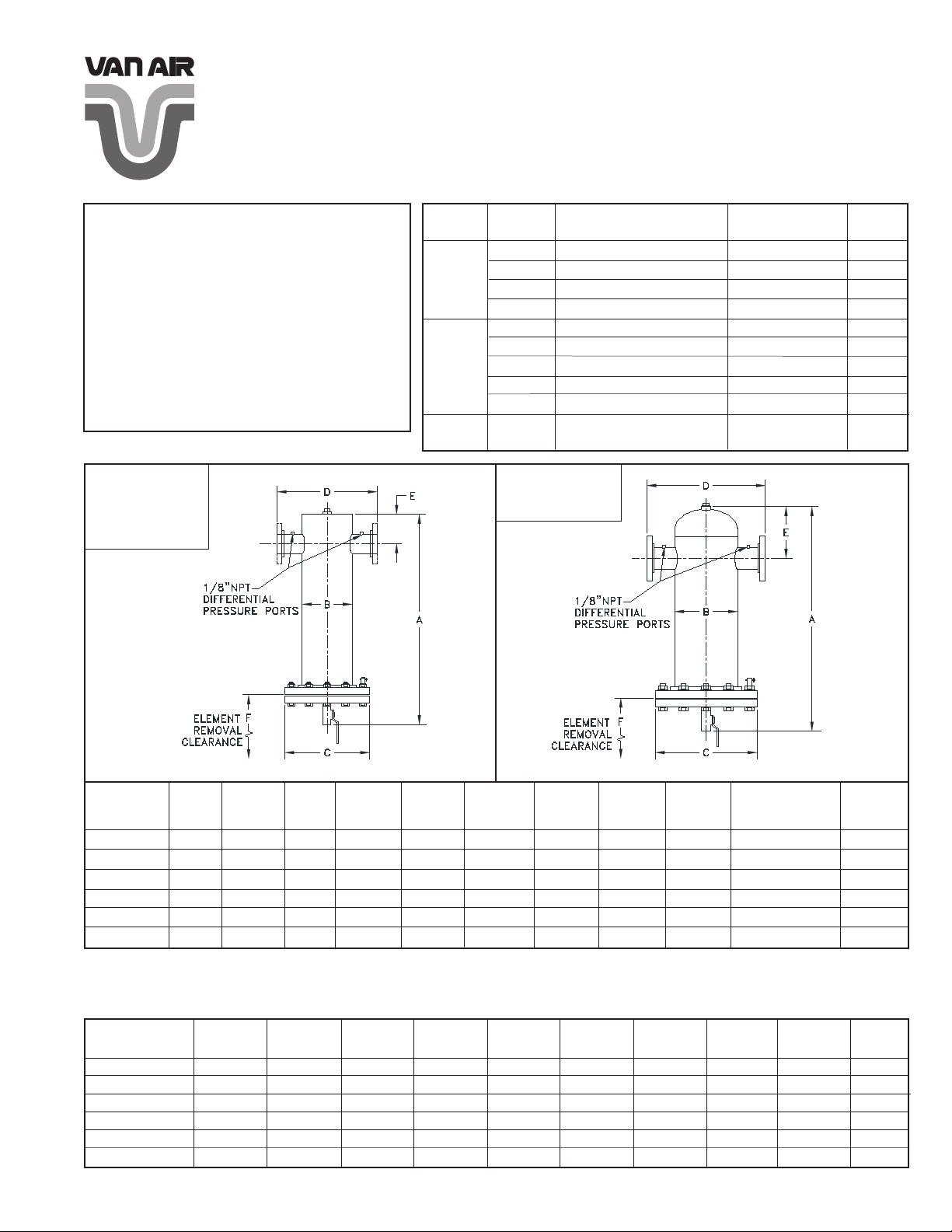
TABLE 3 ENGINEERING DATA
DIMENSIONS FOR:
F101-500
F101-1000
F101-1500
F101-2000
Consult Data Plate
250 PSIG
165 PSIG
35°F
150°F
225°F
175°F
125°F
80°F
450°F
TABLE 2 AVAILABLE ELEMENT GRADES
ELEMENT
Oil
Removal
(Liquid)
Solid
Particle
Removal
Oil Vapor
Removal
GRADE
RAA
DIMENSIONS FOR:
PURPOSE
AA
Extra Coarse Coalescing
A
Coarse Coalescing
B
General Purpose Coalescing
C
High Efciency Coalescing
Extra Coarse Particulate
RA
Coarse Particulate
RB
General Purpose Particulate
RC
High Efciency Particulate
HT
High Temperature Particulate
RD
Vapor Adsorbing
F101-3500
F101-5000
SEPTEMBER 2011
P/N: 32-0129-C
FLOW DIRECTION
THRU ELEMENT
In/Out
In/Out
In/Out
In/Out
Out/In
Out/In
Out/In
Out/In
Out/In
Out/In
COLOR
CODE
Black
Green
Red
Blue
Black
Green
Red
Blue
Zinc Plate
Black
FILTER
MODEL
NO.
F101-500-(*)
F101-1000-(*)
F101-1500-(*)
F101-2000-(*)
F101-3500-(*)
F101-5000-(*)
*Insert appropriate ltration grades here; for example F101-1500-B.
**Flow is based on SCFM @ 100 PSIG @ 100°F.
***Housing weight does not include elements. For element weights see Table 5.
FLOW
(SCFM)
500
1000
1500
2000
3500
5000
IN/OUT
**
CONN.
(INCHES)
2 NPT
3 NPT
3 NPT
4 FLG
6 FLG
6 FLG
DRAIN
CONN.
(NPT)
1/2"
1/2"
1/2"
1/2"
1/2"
1"
A
(INCHES)
39
41-1/8
44-1/2
50-7/8
56-5/8
61-5/8
B
(INCHES)
6-5/8
8-5/8
10-3/4
10-3/4
12-3/4
16
C
(INCHES)
11
13-1/2
16
16
19
23-1/2
D
(INCHES)
11-7/8
15-1/2
17-3/4
18
24-3/4
28
E
(INCHES)
4-5/8
5-1/4
6-1/4
6-3/8
14-1/2
16
F
(INCHES)
24
24
24
30
30
30
BOTTOM BLIND
FLANGE WEIGHT
(LBS.)
28
47
69
69
102
177
HOUSING
***
WEIGHT
(LBS.)
110
150
250
265
390
600
TABLE 4 FLOW CAPACITIES AT VARIOUS OPERATING PRESSURES (SCFM)
MODEL NO.
F101-500-(*)
F101-1000-(*)
F101-1500-(*)
F101-2000-(*)
F101-3500-(*)
F101-5000-(*)
*Insert appropriate ltration grades here; for example F101-1500-B.
PAGE 1
25
PSIG
175
345
520
690
1210
1730
50
PSIG
280
565
845
1130
1975
2820
75
PSIG
390
780
1175
1565
2735
3910
100
PSIG
500
1000
1500
2000
3500
5000
125
PSIG
610
1220
1825
2435
4265
6090
150
PSIG
720
1435
2155
2870
5025
7180
175
PSIG
825
1655
2480
3310
5790
8270
200
PSIG
935
1870
2810
3745
6550
9360
225
PSIG
1045
2090
3135
4180
7315
10,450
250
PSIG
1155
2310
3460
4615
8080
11,540
Page 2
WARNINGS
DO NOT REMOVE, REPAIR OR REPLACE ANY ITEM ON VESSEL WHILE IT IS UNDER PRESSURE.
DO NOT OPERATE IF THERE IS A LEAK IN VESSEL. TAKE VESSEL OUT OF SERVICE IMMEDIATELY AND NOTIFY YOUR
CERTIFYING AUTHORITY.
DO NOT OPERATE ABOVE MAXIMUM WORKING PRESSURE (MWP) AT MAXIMUM OPERATING TEMPERATURE (°F)
SHOWN ON ASME NAMEPLATE.
THIS ASME CODE VESSEL MUST BE PROTECTED BY A PRESSURE RELIEF VALVE. Refer to OSHA 1910.169 Par b, Sub
Par (3) and ASME Boiler and Pressure Vessel Code, Section VIII, Div 1 UG-125, Par (1). Also check government regulations, i.e.,
state and local codes.
DO NOT WELD, GRIND OR SAND VESSEL. IT WILL NOT BE SAFE TO OPERATE.
DO NOT OPERATE VESSEL IF THERE HAS BEEN A FIRE. TAKE VESSEL OUT OF SERVICE IMMEDIATELY AND NOTIFY
YOUR CERTIFYING AUTHORITY.
ANY DAMAGE TO VESSEL CAN MAKE IT UNSAFE. INSPECT OUTSIDE AND INSIDE OF VESSEL REGULARLY FOR CORROSION OR ANY DAMAGE (i.e., DENTS, GOUGES OR BULGES). IF DAMAGED OR CORRODED TAKE OUT OF SERVICE
IMMEDIATELY AND NOTIFY YOUR CERTIFYING AUTHORITY.
USE THE PROPER RULES FOR THE GAS BEING PROCESSED.
INSTALLATION (PART 1 FILTER HOUSING)
Locate compressed air and gas lters at the point of lowest
1.
operating temperatures to ensure that water and oil vapor will
not condense downstream of the lter.
Filters should be installed close to the point of use to mini-
2.
mize the risk of pipe scale, dirt, etc. recontaminating the
compressed air or gas. This is particularly important when
installing new lters on an existing installation which has not
had proper ltration.
Protect lters from reverse ow conditions. Do not install
3.
lters downstream of quick opening valves.
Before installing lter check ambient and operating tempera-
4.
ture and pressure conditions to verify that they are within the
specied ranges. (See Table 1). Also verify that system ow
rate corresponds to the rated capacity of the lter. (See Table
4). Operating lter at ows above rated capacity will result in
increased pressure drop. Do not use reducers to match lter
inlet size. The resulting restriction will cause high pressure
drop.
5.
Install lter in vertical position. Provide required minimum
clearance below lter to allow for replacement of elements.
(See Table 3).
Install inlet and outlet shutoff valves to facilitate replacement
6.
of elements. By-pass piping is recommended.
FIGURE 1 LONG FLANGE BOLT (Element access)
NOTE
Vessel models F101-500 thru
F101-2000 are equipped with a
single long ange bolt to permit
rotating of blind ange for access
to elements.
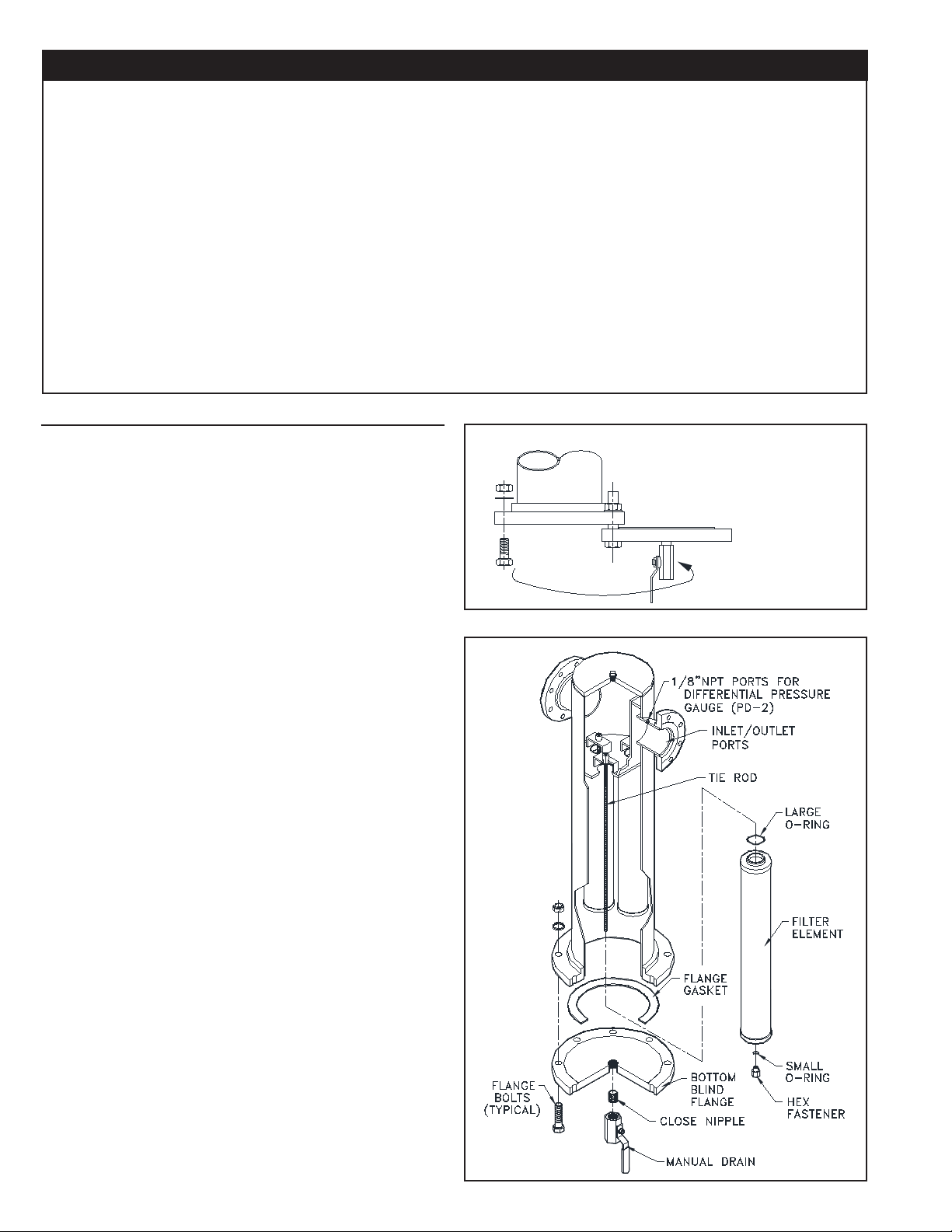
FIGURE 2 TYPICAL ASSEMBLY
Check labels on lter housing, and connect piping so that air
7.
ows through inlet and outlet ports as indicated. Make sure
air ow through lter element is correct. Improper ow direction can minimize lter performance. (See Table 2).
Install differential pressure gauge (optional) on lter housing
8.
using instructions provided with gauge kit. Differential pres-
sure is used to monitor element life (except grade RD) and
indicates when an element change is required.
(See Table 6).
Insert close nipple in threaded hole on bottom blind ange
9.
and tighten securely. Screw manual drain valve on close
nipple and tighten. (See Figure 2). When automatic draining
is required, a motorized ball valve or solenoid type is recommended.
PAGE 2
Page 3

INSTALLATION (PART 2 ELEMENT)
WARNING
DO NOT LOOSEN FLANGE BOLTS BEFORE THE VESSEL HAS BEEN COMPLETELY DEPRESSURIZED.
Provide support under blind ange to prevent it from falling
1.
when bolts are removed. Blind anges are heavy and could
cause injury if allowed to fall.
(See Table 3 for blind ange weights).
Remove bolts from ange and lower blind ange for access
2.
to elements. Filter models F101-500 through 2000 are
equipped with a single long ange bolt to permit rotation of
blind ange for access to elements. (See Figure 1).
6.
the element(s) are held rmly in place. Do not over tighten.
(See Figure 2).
Before closing housing, inspect bafe to make certain that
7.
new elements have been installed in each position.
(See Table 5 for element replacement data).
With gasket in place, carefully raise or swing blind ange
8.
into place and align bolt holes. Insert all bolts and completely tighten all nuts evenly.
Close drain valve; then slowly open inlet and outlet valves.
9.
Close by-pass valves if provided.
Filter is now in service.
10.
Element(s) are shipped separately and must be in-
3.
stalled before lter is ready for service. Remove hex
fasteners(s) from tie rod(s) in housing.
Remove element(s) from packaging and remove o-ring(s)
4.
from bottom end cap(s) of element(s). Install o-ring(s) in oring groove(s) on hex fastener(s). (See Figure 2).
Install element(s) in housing so that the tie rod protrudes
5.
through small hole in bottom end cap.
Thread hex fastener(s) onto the tie rod(s) and tighten so that
REPLACEMENT PARTS
TABLE 5 REPLACEMENT PARTS
FILTER
MODEL NO.
F101-500-(*)
F101-1000-(*)
F101-1500-(*)
F101-2000-(*)
F101-3500-(*)
F101-5000-(*)
*Insert appropriate ltration grades here; for example F101-3500-C and
replacement element E101/102-625-C (ve required).
REPLACEMENT
ELEMENT MODEL
NUMBER
E101/102-500-(*)
E101/102-500-(*)
E101/102-500-(*)
E101/102-625-(*)
E101/102-625-(*)
E101/102-625-(*)
ELEMENT
WEIGHT
LBS
2.8
2.8
2.8
3.2
3.2
3.2
MAINTENANCE
Drain oil removal lters every shift.
•
Check differential pressures regularly on coalescing and
•
particulate lters (AA, A, B, C, RA, RB, RC, and HT grades).
When differential pressure reaches 10 psid, install clean elements. On adsorbing lters (grade RD), install clean elements
when hydrocarbon vapors are rst detected downstream or
every six months, whichever comes rst.
For correct replacement element model numbers, see label on
•
lter housing and/or the bottom endcap of the element.
(Refer to Table 5).
NUMBER OF
ELEMENTS IN
HOUSING
1
2
3
3
5
8
HOUSING
GASKET
18-0207
18-0206
18-0210
18-0210
18-0209
18-0211
HEX
FASTENER
26-3258
26-3258
26-3258
26-3258
26-3258
26-3258
MANUAL DRAIN
VALV E
14-0450
14-0450
14-0450
14-0450
14-0450
14-0451
ACCESSORIES
TABLE 6 DIFFERENTIAL PRESSURE GAUGE KITS:
PART
NUMBER
29-0370
29-0371
84-0129
84-0131
84-0130
84-0211
PAGE 3
MODEL NUMBER
PD-2 GAUGE
PD-2/SW GAUGE
PD-2 KIT
PD-2/SW KIT
PD-2/HT KIT
PD-2/HT SW KIT
DESCRIPTION
Differential pressure gauge. (Only)
Differential pressure gauge with N.O. reed switch. (Only)
Differential pressure gauge with nylon tubing and brass tube ttings.
Differential pressure gauge with N.O. reed switch, nylon tubing and brass tube ttings.
Differential pressure gauge with stainless steel tubing and steel tube ttings (for HT units).
Differential pressure gauge with N.O. reed switch, stainless steel tubing and steel tube ttings (for HT units).
Page 4

TROUBLESHOOTING
CONDITION
Initial pressure
drop too
high
Oil carryover
Short element
life
POTENTIAL CAUSE
Filter undersized for ow rate.
Filter grade too ne.
Filter inlet smaller than pipe size.
Oil present in system before installing lter.
Excessive inlet oil > 50ppm.
Filter installed backwards.
Filter bowl not being drained.
High differential pressure.
Defective seal.
Incorrect replacement element.
By-pass valve leaking or open
Unltered air entering from source down stream of lter.
High operating temperatures.
Cooling by refrigerated dryer.
Excessive particulate contamination.
High compression temperatures causing varnish/carbon
formation.
Oil water emulsion overloading element.
High viscosity oil or freeze-up due to low ambient tem-
perature.
RECOMMENDATION
Install larger lter.
Install coarser grade element.
Install larger lter.
Clean piping.
Check compressor and/or air/oil separator if compressor is rotary vane
or screw. Lower lube rate if reciprocating compressor. Install coarse
coalescer for preltration.
Check installation instructions.
Check and repair auto drain. Drain frequently if manual valve.
Check element if excessive (7-10 psid or above).
Check o-ring in element.
Check and use ner grade.
Close valve. Check seals.
Relocate lter or install additional lter.
Install, clean, replace or relocate aftercooler.
Install grade B or C lter downstream of dryer.
Install coarse coalescing lter immediately upstream of existing lter.
Use compressor lubricant with good temperature stability. Lower lube
rates where possible. Use coarser grade lter element.
Inspect separator. Remove water with better separation.
Raise ambient temperatures. Heat trace inlet piping and housing.
PAGE 4
2950 Mechanic Street
Lake City, PA 16423-2095
Phone: 800/840-9906
Fax: 814/774-3482
www.vanairsystems.com
 Loading...