

Toyota Camry 2007-2009 Service Manual - U660E_Automatic_Transaxle

U660E AUTOMATIC TRANSAXLE – AUTOMATIC TRANSAXLE SYSTEM
AUTOMATIC TRANSAXLE
SYSTEM
PRECAUTION
AX–1
NOTICE:
• If the following parts ha ve been replaced, initialize the
TCM and perform a road test to allow the TCM to learn
(See page AX-25).
– Valve body assembly
– Shift solenoid SL3
– Shift solenoid SL4
• If the following parts have been replaced, perform a
road test to allow the TCM to learn (See page AX-25).
– Shift solenoid SL1
– Shift solenoid SL2
• If the TCM or transaxle has been replaced, register the
transmission compensation code in the TCM (See
page AX-19).
• Perform the RESET MEMORY (AT initialization) when
replacing the automatic transmission assembly,
engine assembly or ECM (See page AX-25).
1. The automatic transaxle is composed of highly
precision-finished part s which need careful inspection
before reassembly. Even a small nick could cause
fluid leakage or affect transmission performance. The
instructions here are organized so that you work on
only one component group at a time. This will help
avoid confusion caused by similar-looking parts of
different sub-assemblies being on your workbench at
the same time. The component groups are inspected
and repaired from the converter housing side.
Complete as much as possible of the inspection,
repair and reassembly before proceeding to the next
component group. If a defect is found in a certain
component group during reassembly, inspect and
repair this group immediately. If a component group
cannot be assembled because some parts are being
ordered, be sure to keep all parts of the group in a
separate container while proceeding with
disassembly, inspection, repair and reassembly of
other component groups. Recommended: ATF WS
2. All disassembled parts should be washed clean and
any fluid passages and holes should be blown
through with compressed air.
3. Dry all parts with compressed air. Never use a shop
rag or a piece of cloth to dry them.
4. When using compressed air, always aim away from
yourself to prevent accidentally spraying ATF or
kerosene in your face.
5. Only recommended automatic transmission fluid or
kerosene should be used for cleaning.
AX

AX
AX–2
U660E AUTOMATIC TRANSAXLE – AUTOMATIC TRANSAXLE SYSTEM
6. After cleaning, the parts should be arranged in the
correct order for efficient inspection, repair, and
reassembly.
7. When disassembling a valve body, be sure to match
each valve together with its corresponding spring.
8. New discs for the brakes and clutches must be soaked
in ATF for at least 15 minutes before reassembly.
9. All oil seal rings, clutch discs, clutch plates, rotating
parts, and sliding surfaces should be coated with ATF
prior to reassembly.
10.All gaskets, seals, and rubber O-rings should be
replaced with new ones.
11.Do not apply adhesive cement s to g asket s and si milar
parts.
12.Make sure that the ends of a snap ring are not aligned
with one of the cutouts and that the snap ring is
installed in the groove correctly.
13.When replacing a worn bushing, the sub-assembly
containing the bushing must also be replaced.
14.Check thrust bearings and races for wear or damage.
If they are damaged, replace them.
15.When working with FIPG material, you must observe
the following:
– Using a razor blade and a gasket scraper, remove
all the old packing (FIPG) material from the gasket
surface.
– Thoroughly clean all components to remove any
loose material.
– Clean both sealing surfaces with a non-residue
solvent.
– Parts must be reassembled within 10 minutes of
application. Otherwise, the packing (FIPG) material
must be removed and reapplied.
1. EXPRESSIONS OF IGNITION SWITCH
The type of ignition switch used on this model differs
according to the specifications of the vehicle.
The expressions listed in the table below are used in this
section.
Expression
Ignition switch off LOCK Off
Ignition switch on (IG) ON On (IG)
Ignition switch on (ACC) ACC ON (ACC)
Engine start START Start
Ignition Switch (Position) Engine Switch (Condition)
Switch Type
U660E AUTOMATIC TRANSAXLE – AUTOMATIC TRANSAXLE SYSTEM
AX–3
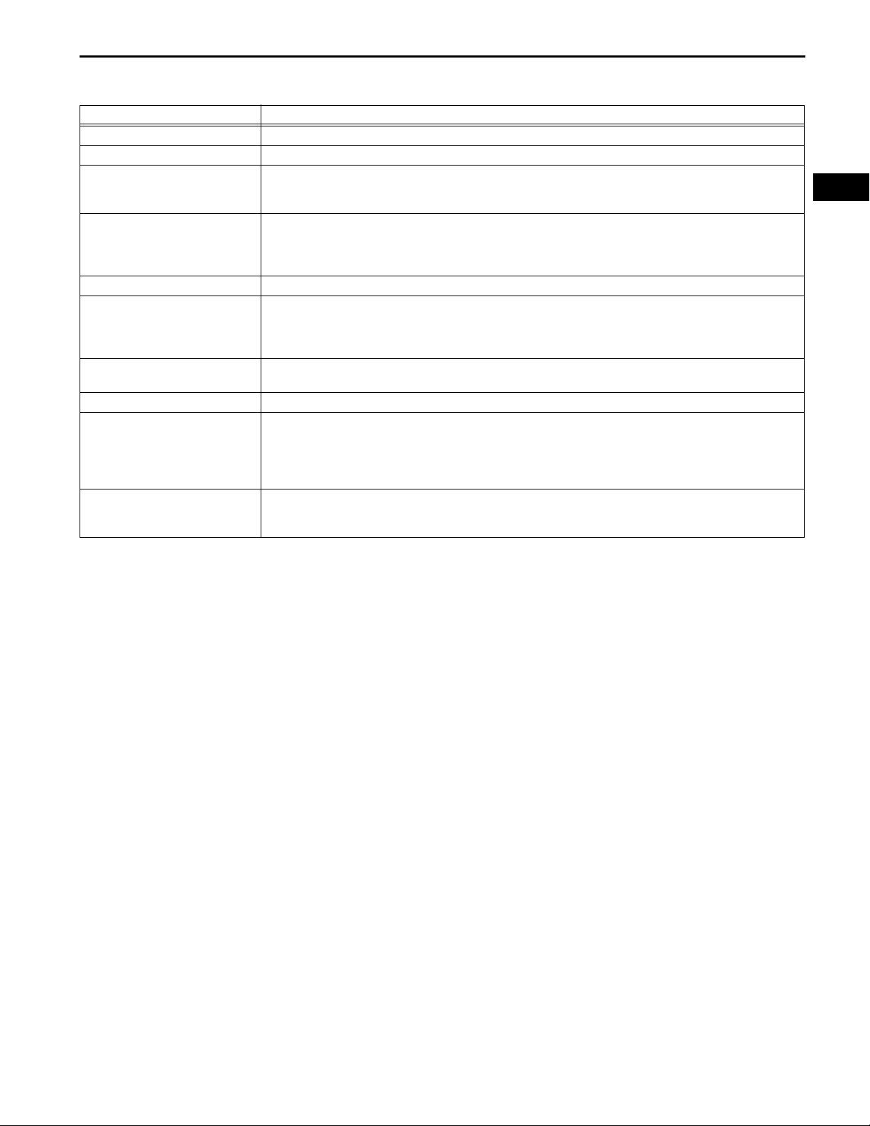
DEFINITION OF TERMS
Term Definition
Monitor description Description of what the TCM monitors and how it detects malfunctions (monitoring purpose and its details).
Related DTCs Diagnostic code
Preconditions that allow the TCM to detect malfunctions.
Typical enabling condition
Sequence of operation
Required sensor/components The sensors and components that are used by the TCM to detect malfunctions.
Frequency of operation
Duration
Malfunction thresholds Beyond this value, the TCM will conclude that there is a malfunction and set a DTC.
MIL operation
Component operating range
With all preconditions satisfied, the TCM sets the DTC when the monitored value(s) exceeds the
malfunction threshold(s).
The priority order that is applied to monitoring, if multiple sensors and components are used to detect the
malfunction.
While another sensor is being monitored, the next sensor or component will not be monitored until the
previous monitoring has concluded.
The number of times that the TCM checks for malfunctions per driving cycle.
"Once per driving cycle" means that the TCM detects malfunction only one time during a single driving
cycle.
"Continuous" means that the TCM detects malfunction every time when the enabling conditions are met.
The minimum time that the TCM must sense a continuous deviation in the monitored value(s) before
setting a DTC. This timing begins after the "typical enabling conditions" are met.
MIL illumination timing after a defect is detected.
"Immediately" means that the TCM illuminates MIL the instant the TCM determines that there is a
malfunction.
"2 driving cycle" means that the TCM illuminates MIL if the same malfunction is detected again in the 2nd
driving cycle.
Normal operation range of sensors and solenoids under normal driving conditions.
Use these ranges as a reference.
They cannot be used to judge if a sensor or solenoid is defective.
AX
AX
AX–4
U660E AUTOMATIC TRANSAXLE – AUTOMATIC TRANSAXLE SYSTEM
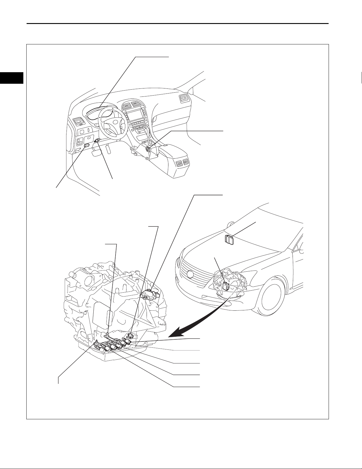
PARTS LOCATION
DLC3
COMBINATION METER
SHIFT LEVER
- TRANSMISSION CONTROL SWITCH
STOP LIGHT SWITCH
PARK / NEUTRAL POSITION SWITCH
SHIFT SOLENOID VALVE (SL)
SPEED SENSOR
ATF TEMPERATURE SENSOR
(INCLUDED ATF PRESSURE SWITCHE)
ECM
TCM
SHIFT SOLENOID VALVE (SLT)
SHIFT SOLENOID VALVE (SLU)
SHIFT SOLENOID VALVE (SL2)
SHIFT SOLENOID VALVE (SL1)
SHIFT SOLENOID VALVE (SL3)
SHIFT SOLENOID VALVE (SL4)
C133208E01
U660E AUTOMATIC TRANSAXLE – AUTOMATIC TRANSAXLE SYSTEM
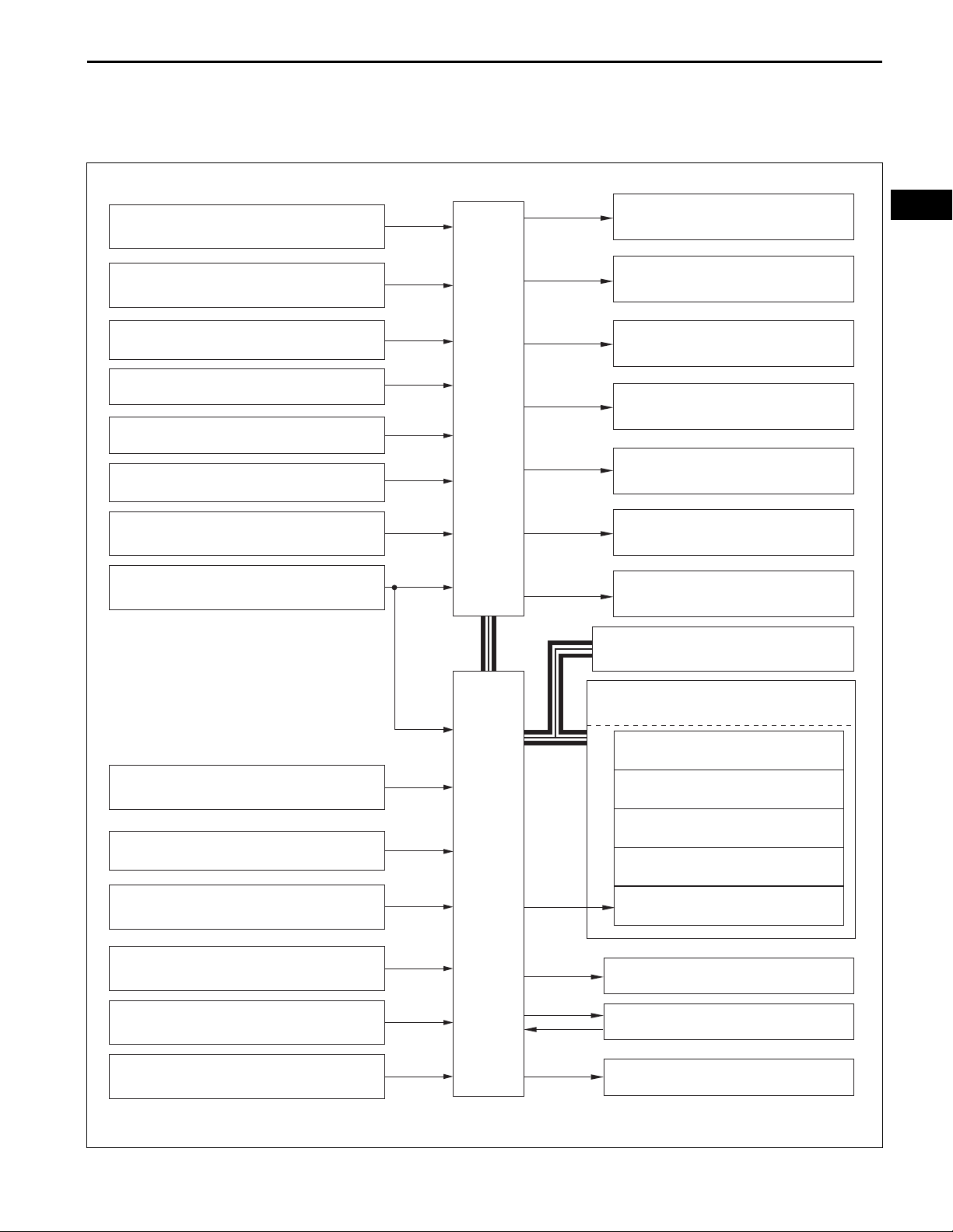
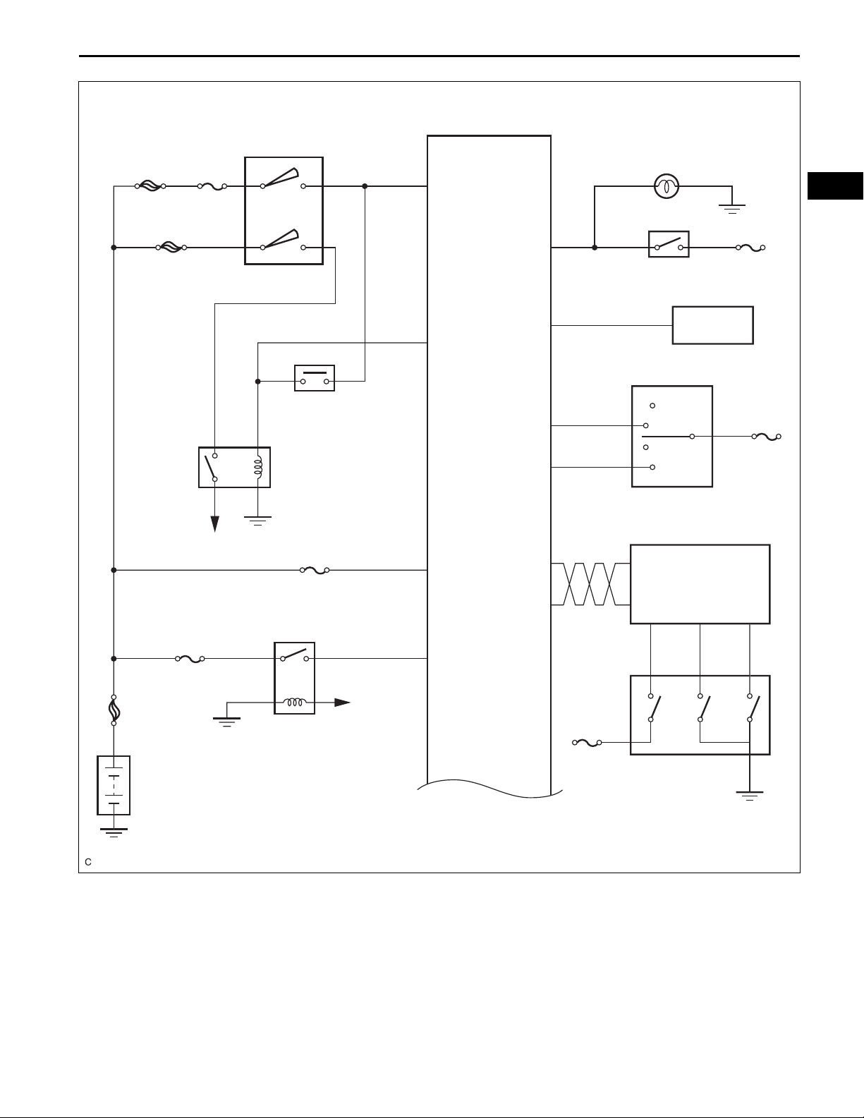
SYSTEM DIAGRAM
The configuration of the electronic control system in the
U660E automatic transaxle is as shown in the following chart.
AX–5
INPUT TURBINE SPEED SENSOR
COUNTER GEAR SPEED SENSOR
ATF PRESSURE SWITCHES
ATF TEMP. SENSOR
STOP LIGHT SWITCH
COMBINATION METER
STARTER RELAY (Starter Signal)
PARK / NEUTRAL POSITION SWITCH
NTO
NCO
TPS1, 2, 3
THO1
STP
SPD
STA
NSW
R,D
CAN+ CAN-
TCM
SL1
SL2
SL3
SL4
SLU
SLT
SL
SOLENOID VALVE SL1
SOLENOID VALVE SL2
SOLENOID VALVE SL3
SOLENOID VALVE SL4
SOLENOID VALVE SLU
SOLENOID VALVE SLT
SOLENOID VALVE SL
DLC3
AX
TRANSMISSION CONTROL SWITCH
MASS AIR FLOW METER
ENGINE COOLANT TEMP. SENSOR
CRANKSHAFT POSITION SENSOR
THROTTLE POSITION SENSOR
ACCELERATOR PEDAL POSITION SENSOR
NSW
P,R,N,D
S,SFTU
SFTD
VG
THW
NE
VPA1
VPA2
VPA
VPA2
ECM
CANH
CANL
W
#10 to #60
IGT1 to 6
IGF
M
COMBINATION METER
Shift Range Indicator Light
Shift Position Indicator Light
S Mode Indicator Light
Buzzer
MIL
FUEL INJECTORS
IGNITION COILS
THROTTLE CONTROL MOTOR
C133209E01
AX
AX–6
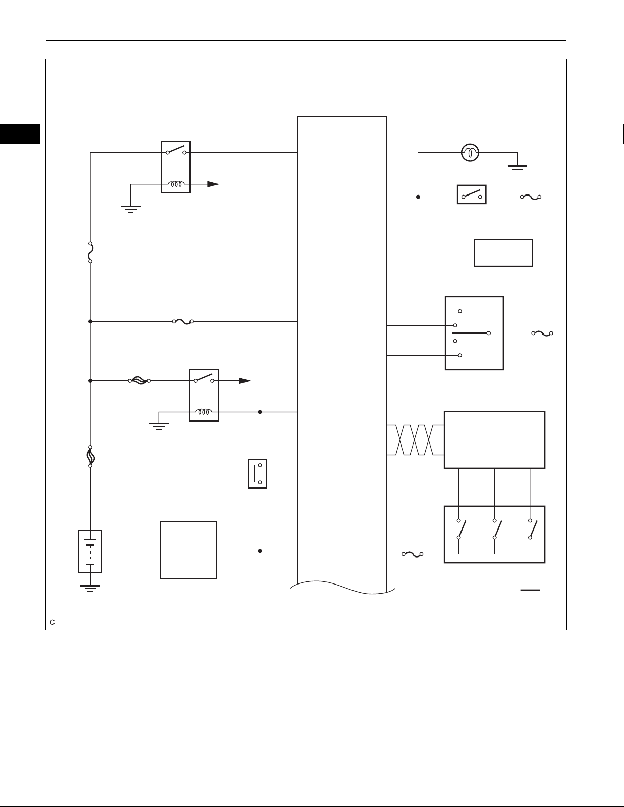
with Smart Key System:
U660E AUTOMATIC TRANSAXLE – AUTOMATIC TRANSAXLE SYSTEM
EFI MAIN
To ECM
+B
TCM
STP
Stop Light
Stop Light Switch
STOP
EFI MAIN
ST/AM2
FL MAIN
EFI No. 1
ST
Park / Neutral
Position Switch
BATT
STA
SPD1
CAN+
CAN-
Combination Meter
R
GAUGE
D
Park / Neutral Position Switch
ECM
S SFTLI SFTD
No. 1
STR
Main Body ECU
NSW
ECU IG
No. 2
Transmission
Control Switch
C133214E05
U660E AUTOMATIC TRANSAXLE – AUTOMATIC TRANSAXLE SYSTEM
without Smart Key System:
AX–7
TCM
ALT AM1
ST/AM2
To Starter
Ignition Switch
Park / Neutral
Position Switch
ST
EFI No. 1
EFI
NSW
STA
BATT
STP
SPD1
CAN+
CAN-
Stop Light
Stop Light Switch
Combination Meter
R
D
Park / Neutral Position Switch
ECM
S
AX
STOP
GAUGE
No. 1
SFTLI SFTD
EFI MAIN
FL MAIN
To ECM
+B
ECU IG
No. 2
Transmission
Control Switch
C133213E01
AX–8
U660E AUTOMATIC TRANSAXLE – AUTOMATIC TRANSAXLE SYSTEM
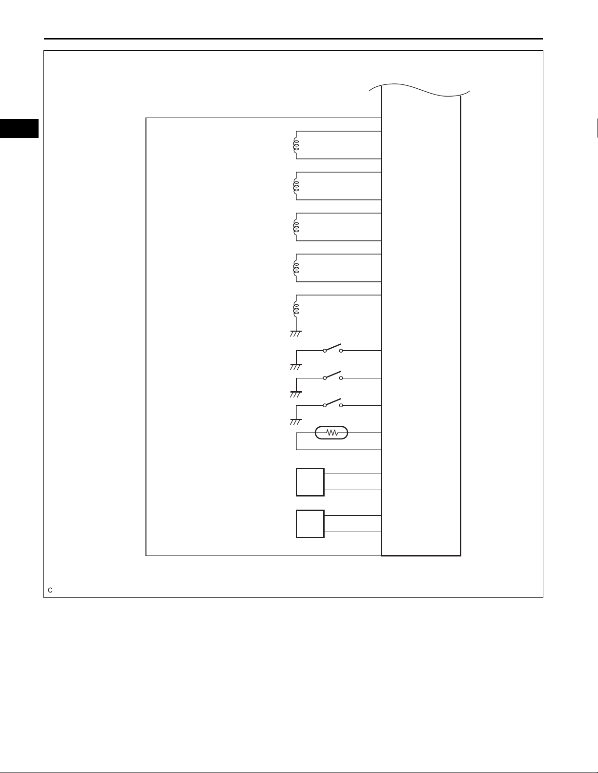
Automatic Transaxle
AX
Shift Solenoid Valve SL1
Shift Solenoid Valve SL2
Shift Solenoid Valve SL3
Shift Solenoid Valve SL4
Shift Solenoid Valve SL
ATF Pressure Switch 1
ATF Pressure Switch 2
ATF Pressure Switch 3
SL1+
SL1SL2+
SL2-
SL3+
SL3SL4+
SL4-
SL
TPS1
TPS2
TPS3
ATF Temperature Sensor
Input Turbine Speed Sensor
Counter Gear Speed Sensor
THO1
E2
NTB
NTO
NCB
NCO
C133215E01

U660E AUTOMATIC TRANSAXLE – AUTOMATIC TRANSAXLE SYSTEM
SYSTEM DESCRIPTION
1. SYSTEM DESCRIPTION
(a) The ECT (Electronic controlled automatic transaxle)
is an automatic transaxle that has its shift timing
electronically controlled by the Transmission Control
Module (TCM). The TCM detects electrical signals
that indicate engine and driving conditions, and
controls the shift point, based on driver's habits and
road conditions. As a result, fuel efficiency and
transaxle performance are improved.
Shift shock has been reduced by controlling the
engine and transaxle simultaneously.
In addition, the ECT has features such as:
• Diagnostic function.
• Fail-safe function for use when a malfunction
occurs.
AX–9
AX
AX
AX–10
1
NEXT
2
NEXT
U660E AUTOMATIC TRANSAXLE – AUTOMATIC TRANSAXLE SYSTEM
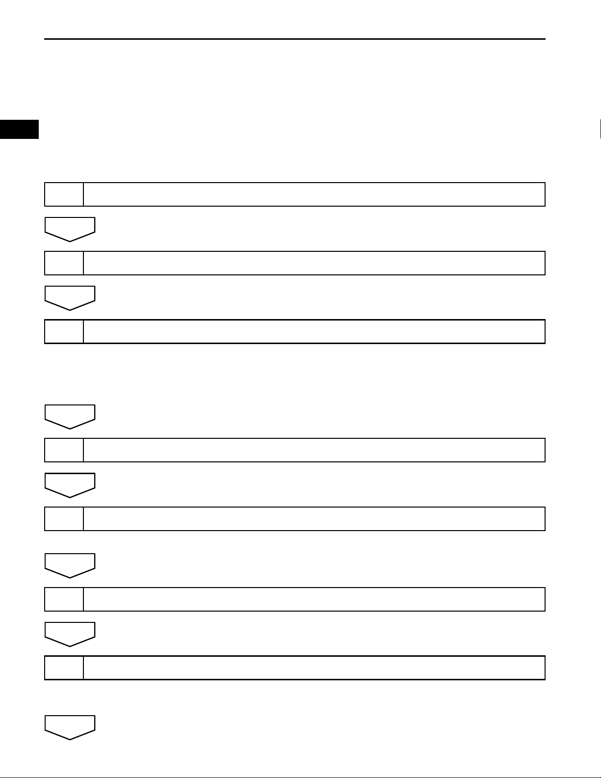
HOW TO PROCEED WITH
TROUBLESHOOTING
HINT:
• The TCM of this system is connected to the CAN
communication system. Therefore, before starting
troubleshooting, make sure to check that there is no
trouble in the CAN communication system.
• *: Use the intelligent tester.
VEHICLE BROUGHT TO WORKSHOP
CUSTOMER PROBLEM ANALYSIS
3
NEXT
4
NEXT
5
NEXT
6
INSPECT BATTERY VOLTAGE
Standard voltage:
11 to 14 V
If the voltage is below 11 V, recharge or replace the battery
before proceeding.
CONNECT INTELLIGENT TESTER TO DLC3*
CHECK AND CLEAR DTCS AND FREEZE FRAME DATA*
(a) Refer to the DTC CHECK / CLEAR (See page AX-38).
VISUAL INSPECTION
NEXT
7
NEXT
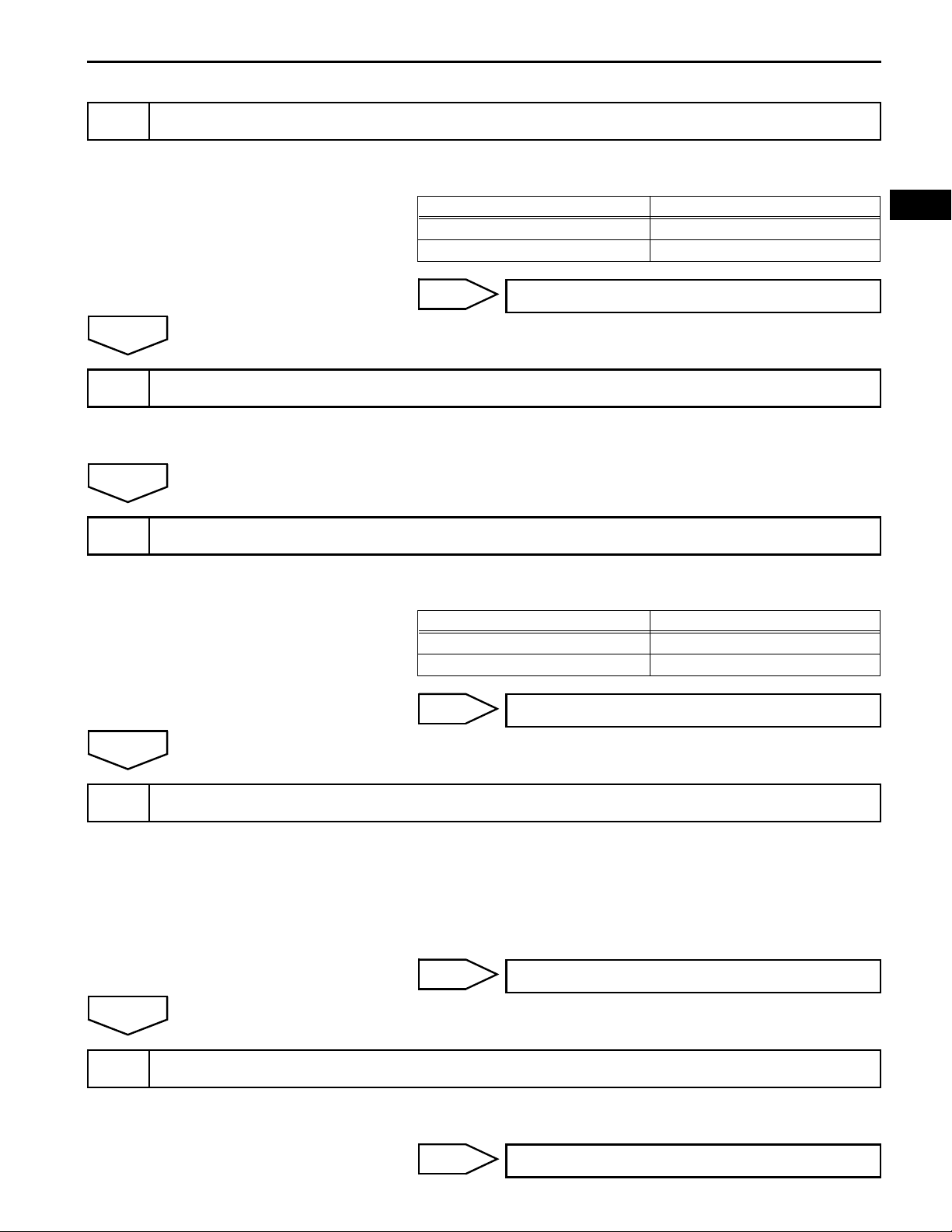
SETTING CHECK MODE DIAGNOSIS*
(a) Refer to the CHECK MODE PROCEDURE (See page
AX-39).
U660E AUTOMATIC TRANSAXLE – AUTOMATIC TRANSAXLE SYSTEM
PROBLEM SYMPTOM CONFIRMATION
8
AX–11
(a) Refer to the ROAD TEST (See page AX-12).
Result
A
9
NEXT
10
SYMPTOM SIMULATION
DTC CHECK*
Result Proceed to
Symptom does not occur A
Symptom occurs B
B
(a) Refer to the ELECTRONIC CIRCUIT INSPECTION
PROCEDURE (See page IN-40).
(a) Refer to the DTC CHECK / CLEAR (See page AX-38).
Result
GO TO STEP 10
Result Proceed to
DTC is not output A
DTC is output B
AX
11
OK
12
A
BASIC INSPECTION
MECHANICAL SYSTEM TEST
B
(a) Refer to the AUTOMATIC TRANSMISSION FLUID (See
page AX-164).
(b) Refer to the PARK/NEUTRAL POSITION SWITCH (See
page AX-174).
(c) Refer to the SHIFT LEVER ASSEMBLY (See page AX-
224).
NG
(a) Refer to the MECHANICAL SYSTEM TEST (See page
AX-15).
NG
GO TO STEP 18
GO TO STEP 21
GO TO STEP 17
AX–12
OK
U660E AUTOMATIC TRANSAXLE – AUTOMATIC TRANSAXLE SYSTEM
AX
13
OK
14
OK
15
HYDRAULIC TEST
(a) Refer to the HYDRAULIC TEST (See page AX-17).
NG
MANUAL SHIFTING TEST
(a) Refer to the MANUAL SHIFTING TEST (See page AX-
18).
NG
PROBLEM SYMPTOMS TABLE CHAPTER 1
(a) Refer to the PROBLEM SYMPTOMS TABLE (See page
AX-29).
NG
GO TO STEP 17
GO TO STEP 16
GO TO STEP 19
OK
16
NEXT
17
18
NEXT
PROBLEM SYMPTOMS TABLE CHAPTER 2
(a) Refer to the PROBLEM SYMPTOMS TABLE (See page
AX-29).
PART INSPECTION
NEXT
DTC CHART
(a) Refer to the DIAGNOSTIC TROUBLE CODE CHART
(See page AX-46).
GO TO STEP 21
19
NEXT
CIRCUIT INSPECTION
U660E AUTOMATIC TRANSAXLE – AUTOMATIC TRANSAXLE SYSTEM
AX–13
20
NEXT
21
NEXT
22
NEXT
END
IDENTIFICATION OF PROBLEM
AX
REPAIR OR REPLACE
CONFIRMATION TEST

AX
AX–14
U660E AUTOMATIC TRANSAXLE – AUTOMATIC TRANSAXLE SYSTEM
ROAD TEST
1. PROBLEM SYMPTOM CONFIRMATION
(a) Based on the result of the customer problem
analysis, try to reproduce the symptoms. If the
problem is that the transaxle does not shift up or
down, or the shift point is too high or too low,
conduct the following road test referring to the
automatic shift schedule and attempt to duplicate
the problem symptoms.
2. ROAD TEST
NOTICE:
Perform the test at the ATF (Automatic T ransmission
Fluid) temperature 50 to 80°C (122 to 176°F) in the
normal operation.
(a) D position test:
Shift into the D position and fully depress the
accelerator pedal and check the following:
(1) Check up-shift operation.
Check that 1 to 2, 2 to 3, 3 to 4, 4 to 5 and 5 to 6
up-shifts take place, and that the shift points
conform to the automatic shift schedule (See
page SS-46).
HINT:
6th Gear Up-shift Prohibition Control
• Engine coolant temperature is 60°C (140°F)
or less and vehicle speed is 50 mph (80 km/
h) or less.
5th Gear Up-shift Prohibition Control
• Engine coolant temperature is 55°C (131°F)
or less and vehicle speed is 32 mph (51 km/
h) or less.
4th Gear Up-shift Prohibition Control
• Engine coolant temperature is 47°C (117°F)
or less and vehicle speed is 31 mph (49 km/
h) or less.
Lock-up Prohibition Control
• Brake pedal is depressed.
• Accelerator pedal is released.
• Engine coolant temperature is 60°C (140°F)
or less.
(2) Check for shift shock and slip.
Check for shock and slip at the 1 to 2, 2 to 3, 3 to
4, 4 to 5 and 5 to 6th up-shifts.
(3) Check for abnormal noise and vibration.
Check for abnormal noise and vibration when
up-shifting from 1 to 2, 2 to 3, 3 to 4, 4 to 5 and 5
to 6 while driving with the shift lever in the D
position, and also while driving in the lock-up
condition.
HINT:
The check for the cause of abnormal noise and
vibration must be done thoroughly as it could
also be due to loss of balance in the differential,
torque converter clutch, etc.

U660E AUTOMATIC TRANSAXLE – AUTOMATIC TRANSAXLE SYSTEM
(4) Check kick-down operation.
Check vehicle speeds when the 2nd to 1st, 3rd
to 2nd, 4th to 3rd, 5th to 4th, and 6th to 5th kickdowns take place while driving with the shift
lever in the D position. Confirm that each speed
is within the applicable vehicle speed range
indicated in the automatic shift schedule (See
page SS-46).
(5) Check for abnormal shock and slip at kick-down.
(6) Check the lock-up mechanism.
• Drive the vehicle with the shift lever in the D
position (2nd, 3rd, 4th, 5th or 6th gear) at a
steady speed (lock-up ON).
• Lightly depress the accelerator pedal and
check that the engine speed does not change
abruptly.
HINT:
• There is no lock-up function in the 1st gears.
• If there is a jump in engine speed, this
indicates that lock-up is not operating.
(b) S position test
Shift to the S position, depress the accelerator pedal
and check the following:
(1) Check shift operation.
• With the shift lever in the S position (while the
vehicle is stopped), shift into the "+" position
to check that the shift position on the
combination meter changes as follows: 1 to 2,
2 to 3, 3 to 4, 4 to 5 and 5 to 6.
• While driving in the 5 (S) position and 5th
gear (at a vehicle speed of approximately 34
to 40 mph (55 to 65 km/h), shift into the "-"
position and check if the 4th gear down-shift
occurs and proper engine braking occurs.
• While driving in the 4 (S) position and 4th
gear (at a vehicle speed of approximately 19
to 25 mph (30 to 40 km/h), shift into the "-"
position and check if the 3rd gear down-shift
occurs and proper engine braking occurs.
• While driving in the 3 (S) position and 3rd
gear (at a vehicle speed of approximately 12
to 19 mph (20 to 30 km/h), shift into the "-"
position and check if the 2nd gear down-shift
occurs and proper engine braking occurs.
• While driving in the 2 (S) position and 2nd
gear (at a vehicle speed of approximately 6 to
12 mph (10 to 20 km/h), shift into the "-"
position and check if the 1st gear down-shift
occurs and proper engine braking occurs.
HINT:
Manual shift (S position) is prohibited under
either of the following conditions:
• Down-shifting may cause engine overrun.
AX–15
AX

AX
AX–16
U660E AUTOMATIC TRANSAXLE – AUTOMATIC TRANSAXLE SYSTEM
• The driver continuously down-shifts. (Downshifting to 1st gear may not be performed.)
(c) R position test:
Shift into the R position, lightly depress the
accelerator pedal, and check that the vehicle moves
backward without any abnormal noise or vibration.
CAUTION:
Before conducting this test ensure that the test
area is free from people and obstruction.
(d) P position test:
Stop the vehicle on a grade (more than 5°) and after
shifting into the P position, release the parking
brake. Then, check that the parking lock pawl holds
the vehicle in place.

U660E AUTOMATIC TRANSAXLE – AUTOMATIC TRANSAXLE SYSTEM
Evaluation:
Problem Possible cause
(a) Stall engine speed is low in D position
(b) Stall engine speed is high in D position
MECHANICAL SYSTEM TESTS
1. PERFORM MECHANICAL SYSTEM TESTS
(a) Measure the stall speed.
The object of this test is to check the overall
performance of the transaxle and engine by
measuring the stall speeds in the D position.
NOTICE:
• Driving test should be done on a paved road
(a nonskid road).
• Perform the test at the normal operating ATF
(Automatic Transmission Fluid) temperature
50 to 80°C (122 to 176°F).
• Do not continuously run this test for longer
than 5 seconds.
• To ensure safety, perform this test in a wide,
clear level area which provides good traction.
• The stall test should always be carried out in
pairs. One technician should observe the
conditions of wheels or wheel stoppers from
a safe location outside the vehicle while the
other is doing the test.
(1) Chock the 4 wheels.
(2) Connect the intelligent tester to the DLC3.
(3) Fully apply the parking brake.
(4) Keep your left foot pressed firmly on the brake
pedal.
(5) Start the engine.
(6) Using the intelligent tester, shift into the D
position and hold 3rd gear using active test.
Press all the way down on the accelerator pedal
with your right foot.
(7) Quickly read the stall speed at this time.
Stall speed:
2,520 +- 150 rpm
• Engine power output may be insufficient
• Stator one-way clutch is not operating properly
HINT:
If the value is less than the specified value by 600 rpm or more, the
torque converter could be faulty.
• Line pressure is too low
• Clutch No. 1 (C
• One-way clutch (F
• Improper fluid level
) slipping
1
) is not operating properly
1
AX–17
AX

AX
AX–18
U660E AUTOMATIC TRANSAXLE – AUTOMATIC TRANSAXLE SYSTEM
(b) Measure the time lag.
(1) When the shift lever is shifted while the eng ine is
idling, there will be a certain time lapse or lag
before the shock can be felt. This is used for
checking the condition of the clutches and
brakes.
NOTICE:
• Perform the test at the normal operating
ATF (Automatic Transmission Fluid)
temperature: 50 to 80°C (122 to 176°F).
• Be sure to allow 1 minute interval between
tests.
• Perform the test three times and measure
the time lags. Calculate the average value
of the three time lags.
(2) Connect the intelligent tester to the DLC3.
(3) Fully apply the parking brake.
(4) Start and warm up the engine and check idle
speed.
Idle speed:
approx. 650 rpm (In N position and A/C
OFF)
(5) Shift the lever from N to D position. Using a stop
watch, measure the time from when the lever is
shifted until the shock is felt.
Time lag:
N to D less than 1.2 seconds
(6) In the same way, measure the time lag for N to
R.
Time lag:
N to R less than 1.5 seconds
Evaluation (If N to D or N to R time lag is longer than the specified time):
Problem Possible cause
• Line pressure is too low
N to D time lag is longer
N to R time lag is longer
• Clutch No.1 (C
• One-way clutch (F
• Line pressure is too low
• Brake No. 2 (B
• Brake No. 3 (B
) is worn
1
) is not operating properly
1
) is worn
2
) is worn
3
U660E AUTOMATIC TRANSAXLE – AUTOMATIC TRANSAXLE SYSTEM
SST
Specified line pressure:
Condition
Idling
SST
C133223E01
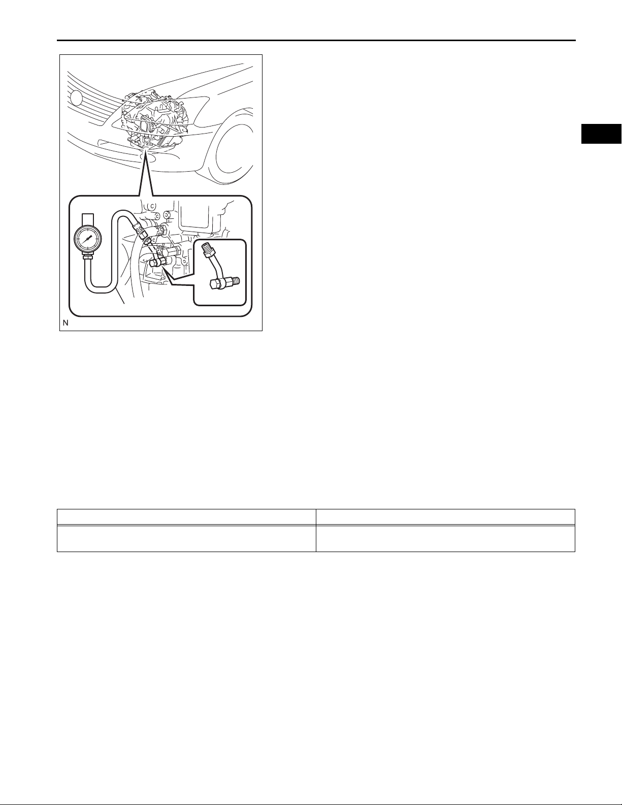
HYDRAULIC TEST
1. PERFORM HYDRAULIC TEST
(a) Measure the line pressure.
NOTICE:
• Perform the test at the normal operating ATF
(Automatic Transmission Fluid) temperature:
50 to 80°C (122 to 176°F).
• The line pressure test should always be
carried out in pairs. One technician should
observe the conditions of wheels or wheel
stoppers outside the vehicle while the other
is performing the test.
• Be sure to prevent SST hose from interfering
with the exhaust pipe.
• This check must be conducted after checking
and adjusting engine.
• Perform the test with the A/C is OFF.
• When conducting stall test, do not continue
more than 5 seconds.
(1) Warm up the ATF (Automatic Transmission
Fluid).
(2) Lift the vehicle up.
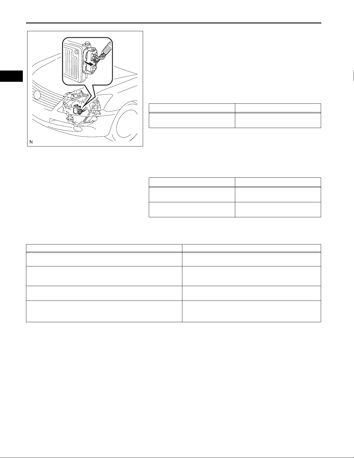
(3) Remove the engine under cover.
(4) Connect the intelligent tester to the DLC3.
(5) Remove the test plug on the transaxle case front
left side and install the SST.
SST 09992-00095 (09992-00231, 09992-
00271)
(6) Start the engine.
(7) Shift to the D position, and then use the
intelligent tester to hold 3rd gear using active
test. Measure the line pressure while the engine
is idling.
D position kPa (kgf/cm
362 to 412 kPa
(3.7 to 4.2 kgf/cm
2
, psi)
2
, 52 to 60 psi)
AX–19
AX
(8) Turn the ignition switch OFF.
AX
AX–20
U660E AUTOMATIC TRANSAXLE – AUTOMATIC TRANSAXLE SYSTEM
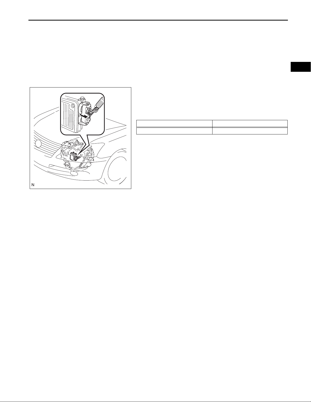
(9) Disconnect the connector of the TCM.
HINT:
Disconnect the connector only when performing
the D position stall test.
(10)Start the engine.
(11)Firmly depress the brake pedal, shift to the D
position, depress the accelerator pedal all the
way down, and check the line pressure while the
stall test is performed.
Specified line pressure:
Condition
Stall test
D position kPa (kgf/cm
1,160 to 1,350 kPa
(11.8 to 13.8 kgf/cm
2
, psi)
2
, 168 to 196 psi)
C133211
Evaluation:
Problem Possible cause
Measured values are higher than the specified value in all positions
Measured values are lower than the specified value in all positions
Pressure is low in the D position only
Pressure is low in the R position only
(12)Turn the ignition switch OFF.
(13)Connect the TCM connector , depress the bra ke
pedal firmly, shift to the R position, and check
that the line pressure while the engine is idling
and during the stall test.
Specified line pressure:
Condition
Idling
Stall test
R position kPa (kgf/cm
806 to 916 kPa
(8.2 to 9.3 kgf/cm
1,890 to 2,000 kPa
(19.3 to 20.4 kgf/cm
2
2
, psi)
, 117 to 133 psi)
2
, 274 to 290 psi)
(14)Remove the SST, install the test plug.
(15)Clear the DTC.
• Shift solenoid valve (SLT) defective
• Regulator valve defective
• Shift solenoid valve (SLT) defective
• Regulator valve defective
• Oil pump defective
• D position circuit fluid leak
• Clutch No. 1 (C
• R position circuit fluid leak
• Brake No. 2 (B
• Brake No. 3 (B
) defective
1
) defective
2
) defective
3
U660E AUTOMATIC TRANSAXLE – AUTOMATIC TRANSAXLE SYSTEM
MANUAL SHIFTING TEST
1. PERFORM MANUAL SHIFTING TEST
HINT:
• With this test, it can be determined whether trouble
occurs in the electrical circuit. Also, trouble can be a
mechanical problem in the transaxle.
• If any abnormalities are found in the following test, the
problem is in the transaxle itself.
(a) Disconnect the TCM connector.
(b) Drive the vehicle with the TCM disconnected.
Shifting the shift lever to the D position to check
whether the shifting condition changes as shown in
the table below.
Shift Position Shifting Condition
D No Shift (No Change)
HINT:
When driving the vehicle with the TCM
disconnected, the gear position will be as follows:
• When the shift lever is in the D position, the
transmission will stay in 3rd gear.
• When the shift lever is in the R or the P position,
C133211
(c) Connect the connector of the TCM.
(d) Clear the DTC (See page AX-38).
the transmission will also be in the R or P
position respectively.
AX–21
AX
AX
AX–22
U660E AUTOMATIC TRANSAXLE – AUTOMATIC TRANSAXLE SYSTEM
REGISTRATION
NOTICE:
• When the automatic transaxle is replaced, the
transaxle's compensation code must be input into the
TCM (Proceed to step 1).
• When the TCM is replaced, the existing transaxle
compensation codes must be input into the new TCM
(Proceed to step 2).
1. INPUT COMPENSATION CODE
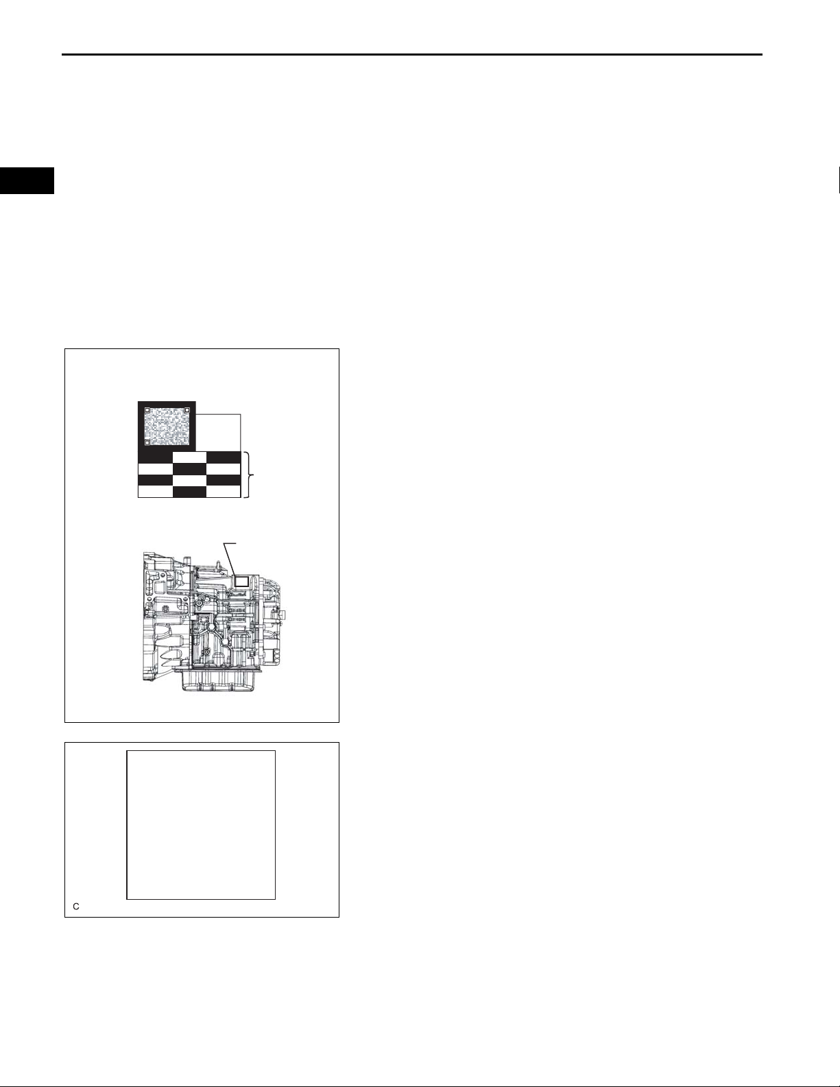
NOTICE:
Transaxle compensation codes are unique, 60-digit
alphanumeric values printed on the QR label. If an
incorrect transaxle compensation code is input into
the TCM, shift shock may occur.
(a) Record the transmission compensation code
specified on the QR label.
QR Code Label
#-
Transmission
Compensation Code
QR Code Label
HINT:
The transaxle compensation code is imprinted on
the QR label.
(b) Shift the shift lever to N or P position.
(c) Connect the intelligent tester to the DLC3.
(d) Turn the ignition switch on (IG).
(e) Turn the tester on.
NOTICE:
Do not start the engine.
M-OBD / OBDΤMENU
[Name of system]
1 : DATA LIST
1 : DTC INFO
3 : ACTIVE TEST
4 : SNAPSHOT
6 : RESET MEMORY
8 : CHECK MODE
9 : AT CODE UTILITY
C133268E01
(f) Enter the menu items in this order: DIAGNOSIS /
OBD/MOBD / ECT / AT CODE UTILITY.
(g) Press "ENTER".
C133193

U660E AUTOMATIC TRANSAXLE – AUTOMATIC TRANSAXLE SYSTEM
AT CODE UTILITY
[Name of system]
1 : AT CODE REGIST
2 : AT CODE RESET
NOTICE
This function is
used to input a
compensation code
and initialize the
ECU after an A/T
assembly or ECU has
been replaced.
PRESS [ENTER]
AX–23
(h) Select "AT CODE REGIST".
(i) Press "ENTER".
AX
C133194
(j) Press "ENTER" again to proceed.
C133195
CHECK
Gear Selector is in P.
Vehicle is stopped.
Engine is OFF.
Engine switch is
ON(IG).
PRESS [ENTER]
NOTICE
This function must
not be performed
without referring
the service manual.
PRESS [ENTER]
A/T CODE REGIST
Select a function.
(k) Press "ENTER" again to proceed.
C133196
(l) Press "ENTER" again to proceed.
C133197
(m) Select "SET A/T CODE".
(n) Press "ENTER".
1. SET A/T CODE
2. READ A/T CODE
PRESS [ENTER]
C133198
AX
AX–24
U660E AUTOMATIC TRANSAXLE – AUTOMATIC TRANSAXLE SYSTEM
A/T CODE REGIST
SET A/T CODE
Select a way of
setting the code.
1. INPUT A/T CODE
2. SAVED A/T CODE
PRESS [ENTER]
(o) Select "INPUT A/T CODE".
(p) Press "ENTER".
C133199
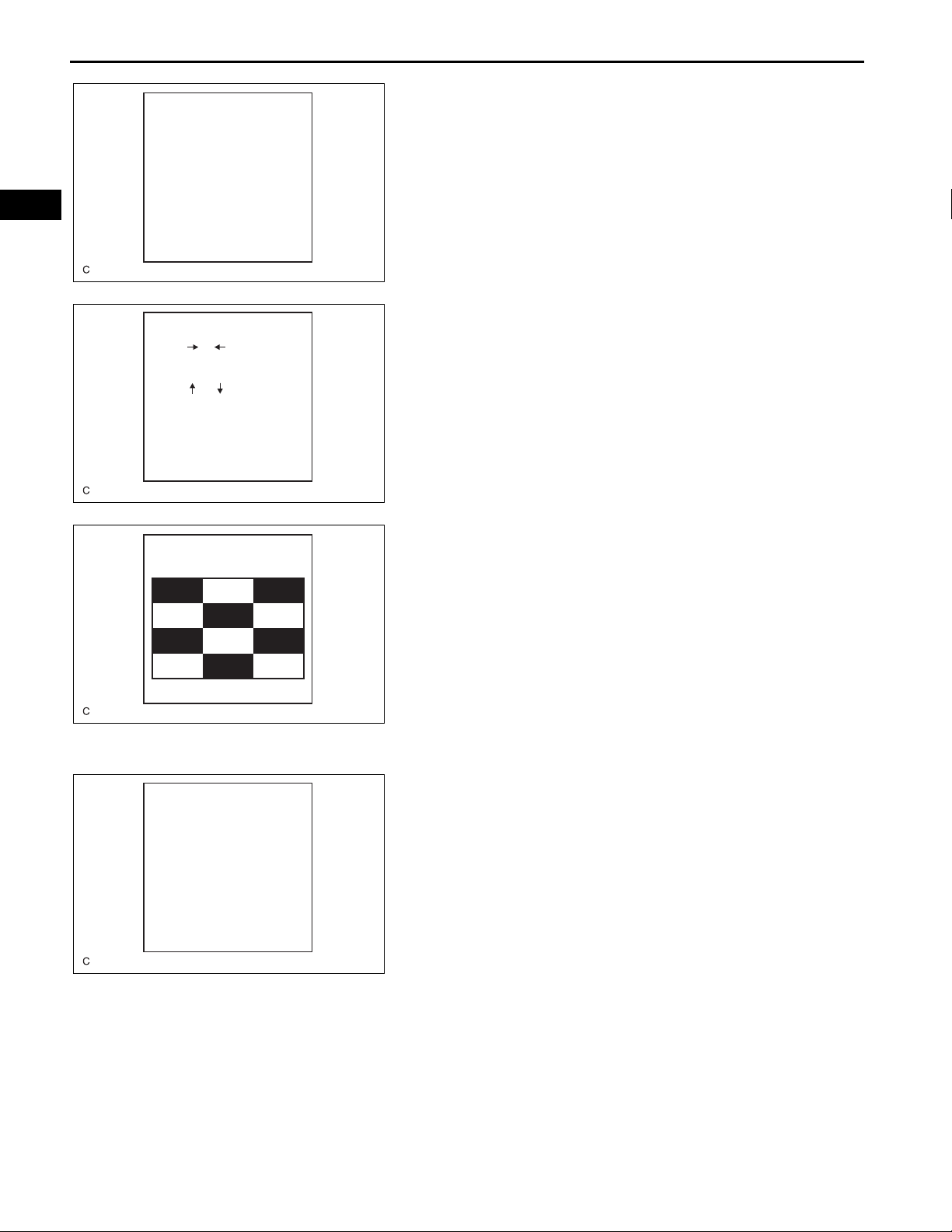
INPUT A/T CODE
code input method
Press [] / [ ] to
shift the cursor
right/left.
Press [] / [ ] to
shift the cursor
up/down.
Input alphanumeric
with 10 key and
* key.
PRESS [ENTER]
A/T CODE REGIST
Input the code
printed on the A/T.
PRESS [ENTER]
C133200
C133201
(q) Register the compensation code.
(1) Press "ENTER".
(2) Manually input the transaxle compensation
code. The code is a 60-digit alphanumeric
value imprinted on the QR label.
(r) Check that the compensation code displayed on the
screen is correct by comparing it with the 60-digit
alphanumeric value on the QR label.
NOTICE:
If an incorrect transaxle compensation code is
input into the TCM, shift shock will occur.
HINT:
Input letters by operating the keys from 0 to 5 while
pressing the * key.
A/T CODE REGIST
SET CODE
A/T CODE REGIST
is complete.
PRESS [EXIT]
C133203
(s) Press "ENTER" to set the compensation code to the
TCM.
HINT:
• If the registration process fails, the compensation
code may be incorrect. Check the compensation
code again.
• If the attempted compensation code is correct, a
problem with the wire harness or a bad
connection with the DLC3 may cause a
registration failure. Check the wire harness and
the DLC3 connection. If no problem is found, the
TCM may be malfunctioning. Check the TCM
and repeat this operation.
2. TRANSFER COMPENSATION CODE
NOTICE:
Transaxle compensation codes are 60-digit
alphanumeric values imprinted on the QR label. If an
incorrect transaxle compensation code is input into
the TCM, shift shock may occur.

U660E AUTOMATIC TRANSAXLE – AUTOMATIC TRANSAXLE SYSTEM
M-OBD / OBDΤMENU
[Name of system]
1 : DATA LIST
1 : DTC INFO
3 : ACTIVE TEST
4 : SNAPSHOT
6 : RESET MEMORY
8 : CHECK MODE
9 : AT CODE UTILITY
AX–25
HINT:
The following operation is available for use with TCMs
that can transmit the registered transaxle compensation
code to the intelligent tester.
(a) Shift the shift lever to N or P position.
(b) Connect the intelligent tester to the DLC3.
(c) Turn the ignition switch on (IG).
(d) Turn the tester on.
NOTICE:
Do not start the engine.
HINT:
The transaxle compensation code is imprinted on
the QR label.
(e) Read the transaxle compensation code.
(1) Enter the menu items in this order:
DIAGNOSIS / OBD/MOBD / ECT / AT CODE
UTILITY.
(2) Press "ENTER".
AX
AT CODE UTILITY
[Name of system]
1 : AT CODE REGIST
2 : AT CODE RESET
NOTICE
This function is
used to input a
compensation code
and initialize the
ECU after an A/T
assembly or ECU has
been replaced.
PRESS [ENTER]
C133193
(3) Select "AT CODE REGIST".
(4) Press "ENTER".
C133194
(5) Press "ENTER" again to proceed.
C133195

AX–26
U660E AUTOMATIC TRANSAXLE – AUTOMATIC TRANSAXLE SYSTEM
AX
CHECK
Gear Selector is in P.
Vehicle is stopped.
Engine is OFF.
Engine switch is
ON(IG).
PRESS [ENTER]
NOTICE
This function must
not be performed
without referring
the service manual.
PRESS [ENTER]
A/T CODE REGIST
Select a function.
(6) Press "ENTER" again to proceed.
C133196
(7) Press "ENTER" again to proceed.
C133197
(8) Select "READ A/T CODE".
(9) Press "ENTER".
1. SET A/T CODE
2. READ A/T CODE
PRESS [ENTER]
A/T CODE REGIST
READ A/T CODE is
completed.
PRESS [EXIT]
C133198
C133206
(10) Press "EXIT".
NOTICE:
Do not use the code specified on the
transaxle QR label even if the transmission
compensation code cannot be read using
the intelligent tester . The code printed on an
in-service transaxle may not match its
current characteristics. Replace the TCM
with a new one and perform a road test to
allow the TCM to learn.
(11) Turn the ignition switch off.
(f) Replace the TCM.
(g) Set the transaxle compensation code.
(1) Turn the ignition switch on (IG).
(2) Turn the tester on.

U660E AUTOMATIC TRANSAXLE – AUTOMATIC TRANSAXLE SYSTEM
M-OBD / OBDΤMENU
[Name of system]
1 : DATA LIST
1 : DTC INFO
3 : ACTIVE TEST
4 : SNAPSHOT
6 : RESET MEMORY
8 : CHECK MODE
9 : AT CODE UTILITY
NOTICE
This function is
used to input a
compensation code
and initialize the
ECU after an A/T
assembly or ECU has
been replaced.
PRESS [ENTER]
AX–27
(3) Enter the menu items in this order:
DIAGNOSIS / OBD/MOBD / ECT / AT CODE
UTILITY.
(4) Press "ENTER".
AX
C133193
(5) Press "ENTER" again to proceed.
C133195
CHECK
Gear Selector is in P.
Vehicle is stopped.
Engine is OFF.
Engine switch is
ON(IG).
PRESS [ENTER]
NOTICE
This function must
not be performed
without referring
the service manual.
PRESS [ENTER]
A/T CODE REGIST
Select a function.
(6) Press "ENTER" again to proceed.
C133196
(7) Press "ENTER" again to proceed.
C133197
(8) Select "SET A/T CODE".
(9) Press "ENTER".
1. SET A/T CODE
2. READ A/T CODE
PRESS [ENTER]
C133198

AX–28
U660E AUTOMATIC TRANSAXLE – AUTOMATIC TRANSAXLE SYSTEM
AX
A/T CODE REGIST
SET CODE
A/T CODE REGIST
is complete.
PRESS [EXIT]
A/T CODE REGIST
SET CODE
A/T CODE REGIST
is complete.
PRESS [EXIT]
(10) Select "SAVED A/T CODE".
(11) Press "ENTER".
C133203
(12) Press "EXIT".
C133203

U660E AUTOMATIC TRANSAXLE – AUTOMATIC TRANSAXLE SYSTEM
M-OBD / OBDΤMENU
[Name of system]
1 : DATA LIST
1 : DTC INFO
3 : ACTIVE TEST
4 : SNAPSHOT
6 : RESET MEMORY
8 : CHECK MODE
9 : AT CODE UTILITY
INITIALIZATION
1. RESET TRANSAXLE COMPENSATION CODE
NOTICE:
The transaxle compensation code can be reset only
with the intelligent tester.
HINT:
The TCM memorizes the condition that the ECT controls
the automatic transaxle assembly and engine assembly
according to those characteristics. Therefore, when the
automatic transaxle assembly , engine assembly, or TCM
has been replaced, it is necessary to reset the memory
so that the TCM can memorize the new information.
Reset procedure is as follows.
(a) Shift the shift lever to N or P position.
(b) Turn the ignition switch off.
(c) Connect the intelligent tester to the DLC3.
(d) Turn the ignition switch on (IG) and push the
intelligent tester main switch on.
(e) Enter the menu items in this order: DIAGNOSIS /
OBD/MOBD / ECT / AT CODE UTILITY.
AX–29
AX
AT CODE UTILITY
[Name of system]
1 : AT CODE REGIST
2 : AT CODE RESET
C133193
C133194
(f) Select "AT CODE RESET".
(g) Press the "ENTER"
CAUTION:
After the transaxle compensation code, be sure
to perform a road test to allow TCM to learn.
2. PERFORM ROAD TEST TO ALLOW TCM TO LEARN
NOTICE:
Perform the following procedures while strictly
observing all traffic laws and speed limits.
(a) From a standstill, achieve highest possible speed
with the accelerator pedal opened 15% or less.
Keep the accelerator pedal angle steady while
driving the vehicle.
(b) Repeat the previous step until shift shock no longer
occurs.
(c) From a standstill, achieve highest possible speed
with the accelerator pedal opened 25% or more.
Keep the accelerator pedal angle steady while
driving the vehicle.
(d) Repeat the previous step until shift shock no longer
occurs.

AX
AX–30
U660E AUTOMATIC TRANSAXLE – AUTOMATIC TRANSAXLE SYSTEM
M-OBD / OBDΤMENU
[Name of system]
1 : DATA LIST
1 : DTC INFO
3 : ACTIVE TEST
4 : SNAPSHOT
6 : RESET MEMORY
8 : CHECK MODE
9 : AT CODE UTILITY
3. RESET MEMORY
NOTICE:
• Perform the RESET MEMORY (AT initialization)
when replacing the engine assembly.
• The RESET MEMORY can be performed only with
the intelligent tester.
HINT:
The ECM memorizes the condition that the ECT controls
the automatic transmission assembly and engine
assembly according to those characteristics. Therefore,
when the automatic transmission assembly, engine
assembly, or ECM has been replaced, it is necessary to
reset the memory so that the ECM can memorize the
new information.
(a) Reset procedure is as follows.
(1) Turn the engine switch off.
(2) Connect the intelligent tester to the DLC3.
(3) Turn the ignition switch on (IG) position.
(4) Turn the intelligent tester main switch on.
(5) Select the item "DIAGNOSIS / OBD/MOBD /
ECT / RESET MEMORY".
NOTICE:
After performing the RESET MEMORY, be
sure to perform the ROAD TEST (See page
AX-12) described previously.
C133193
 Loading...