

2GR-FE ENGINE MECHANICAL – ENGINE
ENGINE
ON-VEHICLE INSPECTION
1. INSPECT ENGINE COOLANT
(a) Inspect the engine coolant (See page CO-1).
2. INSPECT ENGINE OIL
(a) Inspect the engine oil (See page LU-1).
3. INSPECT BATTERY
(a) Inspect the battery (See page CH-4).
4. INSPECT SPARK PLUGS
(a) Inspect the spark plugs (See page IG-5).
5. INSPECT AIR CLEANER FILTER ELEMENT SUBASSEMBLY
(a) Remove the air cleaner filter element sub-assembly.
(b) Visually check that there is no dirt, blockage, and/or
damage to the air cleaner filter element.
HINT:
• If there is any dirt or a blockage in the air cleaner
filter element, clean it with compressed air.
• If any dirt or a blockage remains even after
cleaning the air cleaner filter element with
compressed air, replace it.
EM–1
EM
DLC3
Intelligent Tester
CAN VIM
C110200E02
6. INSPECT VALVE LASH ADJUSTER NOISE
(a) Rev up the engine several times. Check that the
engine does not emit unusual noises.
If unusual noises occur, warm up the engine and
idle it for over 30 minutes. Then repeat this
procedure.
HINT:
If any defects or problems are found during the
inspection above, perform lash adjuster inspection
(See page EM-87).
7. INSPECT IGNITION TIMING
(a) Warm up the engine.
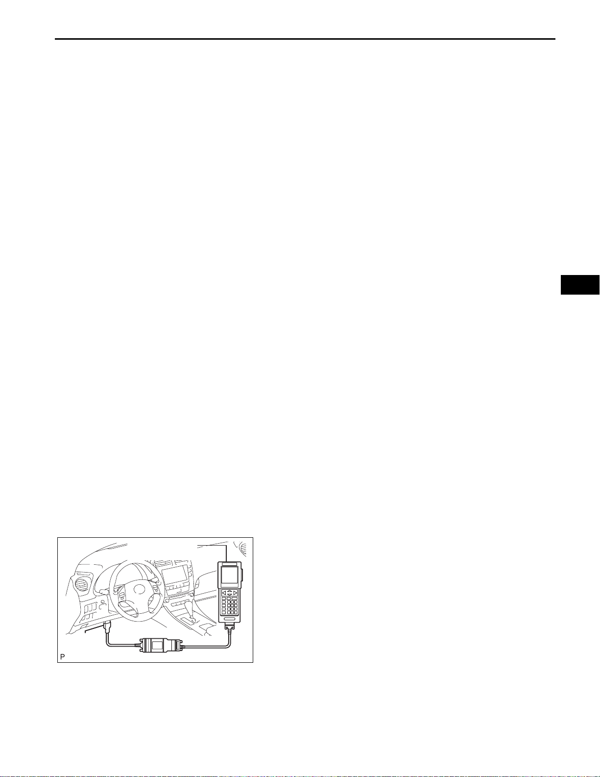
(b) When using the intelligent tester:
Check the ignition timing.
(1) Connect the intelligent tester to the DLC3.
(2) Enter DATA LIST mode with the intelligent
tester.
Ignition timing:
8 to 12° BTDC at idle
HINT:
Refer to the intelligent tester operator's manual
for help when selecting the DATA LIST.
EM–2
DLC3
CG
1
2345678
910111213141516
TC
2GR-FE ENGINE MECHANICAL – ENGINE
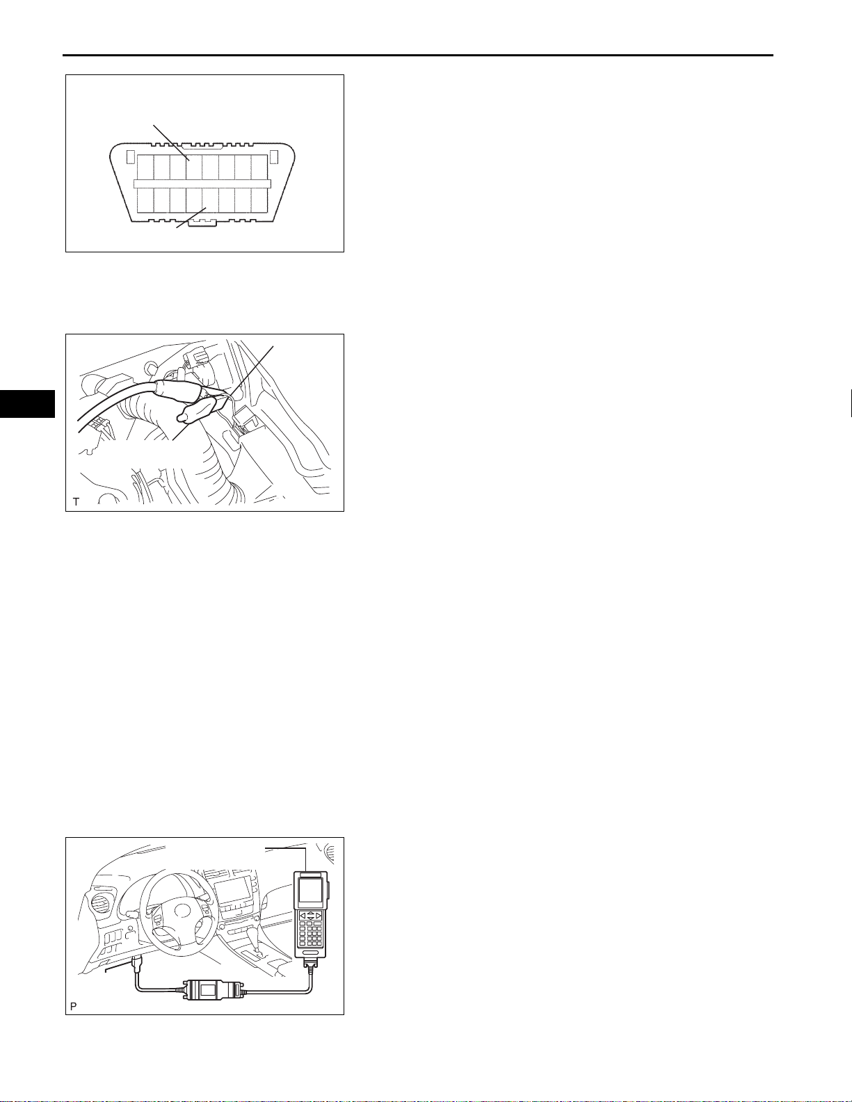
(c) When not using the intelligent tester:
Check the ignition timing.
(1) Using SST, connect terminals 13 (TC) and 4
(CG) of the DLC3.
SST 09843-18040
NOTICE:
• Confirm the terminal numbers before
connecting them. Connection with a
wrong terminal can damage the engine.
A122830E14
• Turn off all electrical systems before
connecting the terminals.
• Perform this inspection after the cooling
fan motor is turned off.
(2) Remove the V-bank cover.
EM
Tester Terminal
Red Lead
Wire
A129620E01
(3) Pull out the red lead wire harness.
(4) Connect the tester terminal of the timing light to
the red lead wire as shown in the illustration.
NOTICE:
Use a timing light which can detect the first
signal.
(5) Check the ignition timing at idle.
Ignition timing:
8 to 12° BTDC at idle
NOTICE:
When checking the ignition timing, the
transmission should be in neutral.
HINT:
Run the engine at 1,000 to 1,300 rpm for 5
seconds, and then check that the engine rpm
returns to idle speed.
(6) Disconnect terminals 13 (TC) and 4 (CG) of the
DLC3.
(7) Check the ignition timing at idle.
Ignition timing:
12 to 22° BTDC at idle
(8) Confirm that the ignition timing moves to the
advanced angle side when the engine rpm is
increased.
(9) Remove the timing light.
DLC3
Intelligent Tester
CAN VIM
C110200E02
8. INSPECT ENGINE IDLE SPEED
(a) Warm up the engine.
(b) When using the intelligent tester:
Check the idle speed.
(1) Connect the intelligent tester to the DLC3.
(2) Enter DATA LIST mode with the intelligent
tester.
Idle speed:
600 to 700 rpm
NOTICE:
• When checking the idle speed, the
transmission should be in neutral.
• Check the idle speed with the cooling fan
off.
TAC
DLC3
1
2345678
910111213141516
2GR-FE ENGINE MECHANICAL – ENGINE
• Switch off all accessories and air
conditioning before connecting the
intelligent tester.
HINT:
Refer to the intelligent tester operator's manual
for further details.
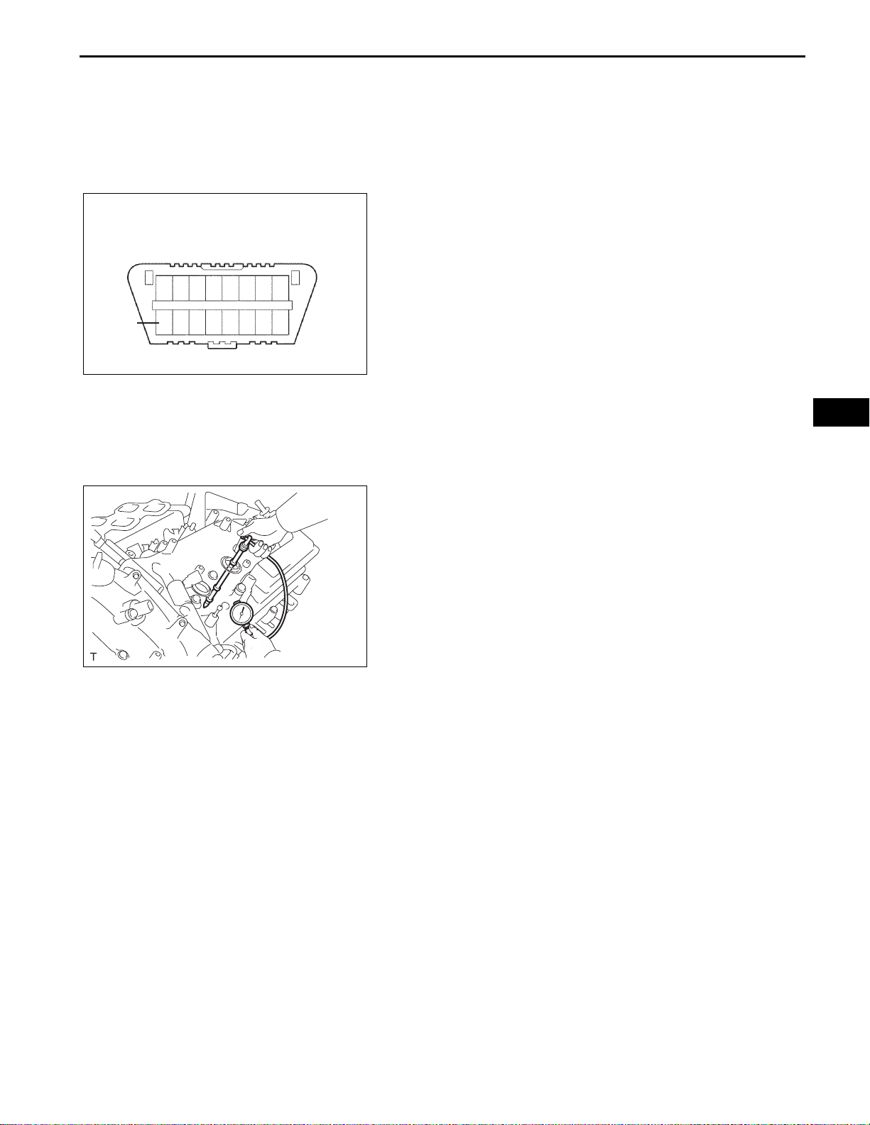
(c) When not using the intelligent tester:
Check the idle speed.
(1) Using SST, connect the tachometer test probe
to terminal 9 (TAC) of the DLC3.
SST 09843-18030
(2) Check the idle speed.
Idle speed:
600 to 700 rpm
EM–3
A122830E15
A129621
9. INSPECT COMPRESSION
(a) Warm up and stop the engine.
(b) Disconnect the injector connectors.
(c) Remove the intake air surge tank (See page FU-
13).
(d) Remove the 6 ignition coils.
(e) Remove the 6 spark plugs.
(f) Check the cylinder compression pressure.
(1) Insert a compression gauge into the spark plug
hole.
(2) While cranking the engine, measure the
compression pressure.
Compression pressure:
1.4 MPa (14 kgf/cm
2
, 199 psi)
Minimum pressure:
2
0.98 MPa (10 kgf/cm
, 142 psi)
Difference between each cylinder:
2
0.1 MPa (1.0 kgf/cm
, 15 psi)
NOTICE:
• Always use a fully charged battery to
obtain an engine speed of 250 rpm or
more.
• Check the other cylinders' compression
pressure in the same way.
• This measurement must be done as
quickly as possible.
(3) If the cylinder compression is low, pour a small
amount of engine oil into the cylinder through
the spark plug hole and inspect again.
HINT:
• If adding oil increases the compression, the
piston rings and/or cylinder bore may be
worn or damaged.
• If pressure stays low, a valve may be stuck
or seated improperly, or there may be
leakage in the gasket.
(g) Install the 6 spark plugs.
Torque: 18 N*m (184 kgf*cm, 13 ft.*lbf)
EM

EM
EM–4
2GR-FE ENGINE MECHANICAL – ENGINE
(h) Install the 6 ignition coils.
Torque: 10 N*m (102 kgf*cm, 7 ft.*lbf)
(i) Install the intake air surge tank. (See page FU-17).
10. INSPECT CO/HC
(a) Start the engine.
(b) Run the engine at 2,500 rpm for approximately 180
seconds.
(c) Insert the CO/HC meter testing probe at least 40 cm
(1.3 ft) into the tailpipe during idling.
(d) Check CO/HC concentration at idle and/or 2,500
rpm.
HINT:
Check regulations and restrictions in your area
when performing 2 mode CO/HC concentration
testing (engine check at both idle speed and at
2,500 rpm).
If the CO/HC concentration does not comply with
regulations, perform troubleshooting in the order
given below.
(1) Check A/F sensor and heated oxygen sensor
operation.
(2) See the table below for possible causes, and
then inspect and repair.
CO HC Problems Causes
1. Faulty ignitions:
– Incorrect timing
Normal High Rough idle
Low High
High High
Rough idle
(fluctuating HC reading)
Rough idle
(black smoke from exhaust)
– Fouled, shorted or improperly g apped plugs
2. Incorrect valve clearance
3. Leaks in intake and exhaust valves
4. Leaks in cylinders
1. Vacuum leaks:
– PCV hoses
– Intake manifold
– Throttle body
– Brake booster line
2. Lean mixture causing misfire
1. Restricted air filter
2. Plugged PCV valve
3. Faulty SFI system:
– Faulty fuel pressure regulator
– Defective ECT sensor
– Defective MAF meter
–Faulty ECM
– Faulty injectors
– Faulty throttle position sensor
ENGINE2GR-FE ENGINE MECHANICAL
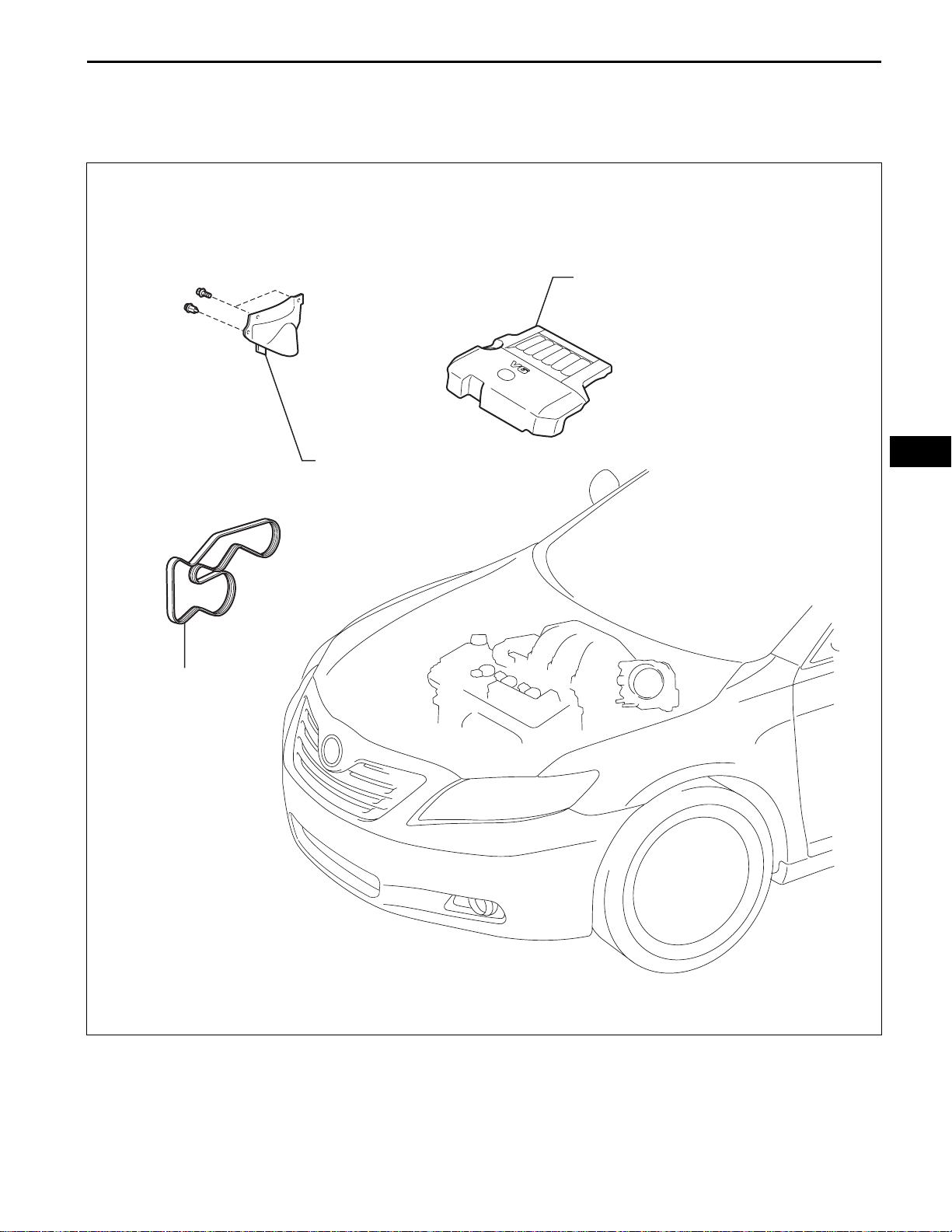
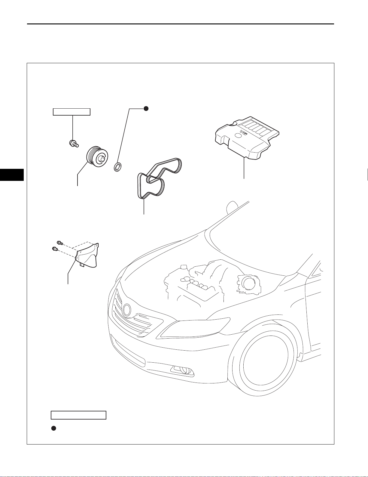
DRIVE BELT
COMPONENTS
2GR-FE ENGINE MECHANICAL – DRIVE BELT
V-BANK COVER SUB-ASSEMBLY
EM–5
V-RIBBED BELT
FRONT FENDER APRON SEAL RH
EM
A134931E01
EM
EM–6
2GR-FE ENGINE MECHANICAL – DRIVE BELT
REMOVAL
1. REMOVE FRONT WHEEL RH
2. REMOVE FRONT FENDER APRON SEAL RH
3. REMOVE V-BANK COVER SUB-ASSEMBLY (See
page EM-23)
4. REMOVE V-RIBBED BELT
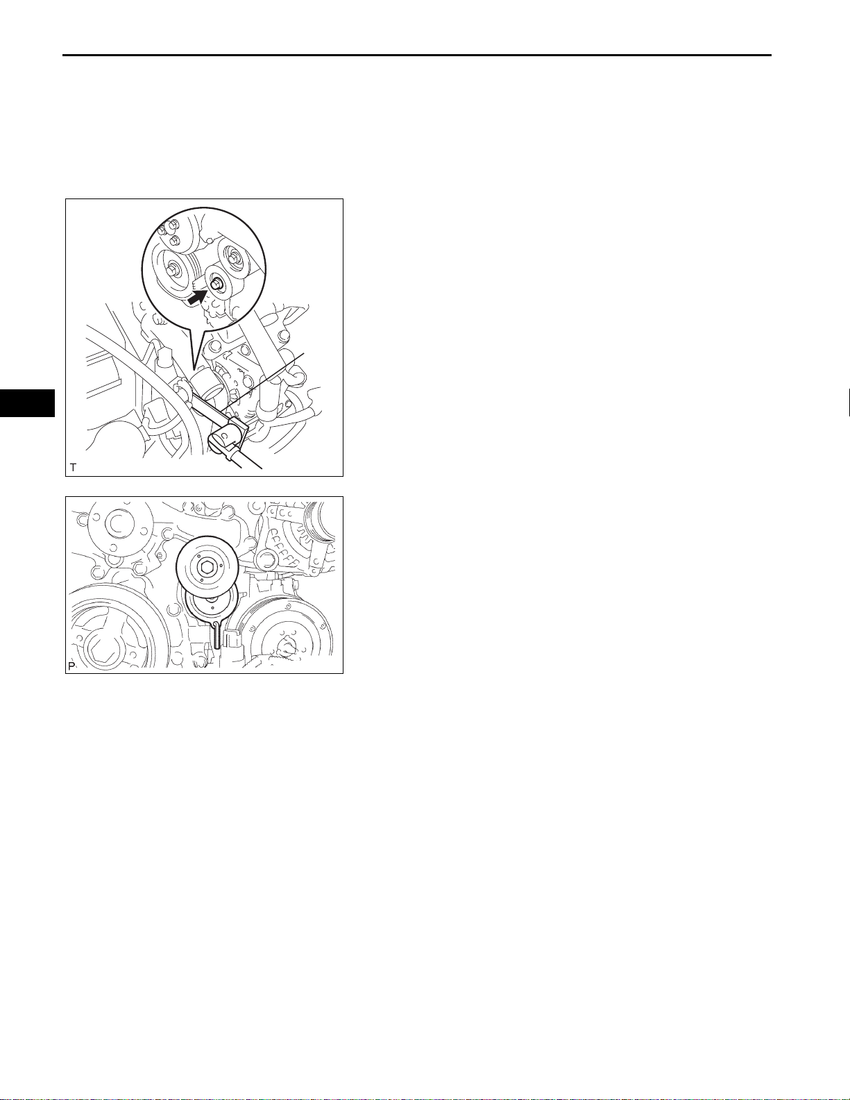
(a) Using SST, release the belt tension by turning the
belt tensioner counterclockwise, and remove the Vribbed belt from the belt tensioner.
SST 09249-63010
SST
A129622E01
A095070
(b) While turning the belt tensioner counterclockwise,
align with its holes, and then insert the 5 mm bihexagon wrench into the holes to fix the V-ribbed
belt tensioner.
2GR-FE ENGINE MECHANICAL – DRIVE BELT
EM–7
REPLACE
CORRECT INCORRECT
A131418E01
INSPECTION
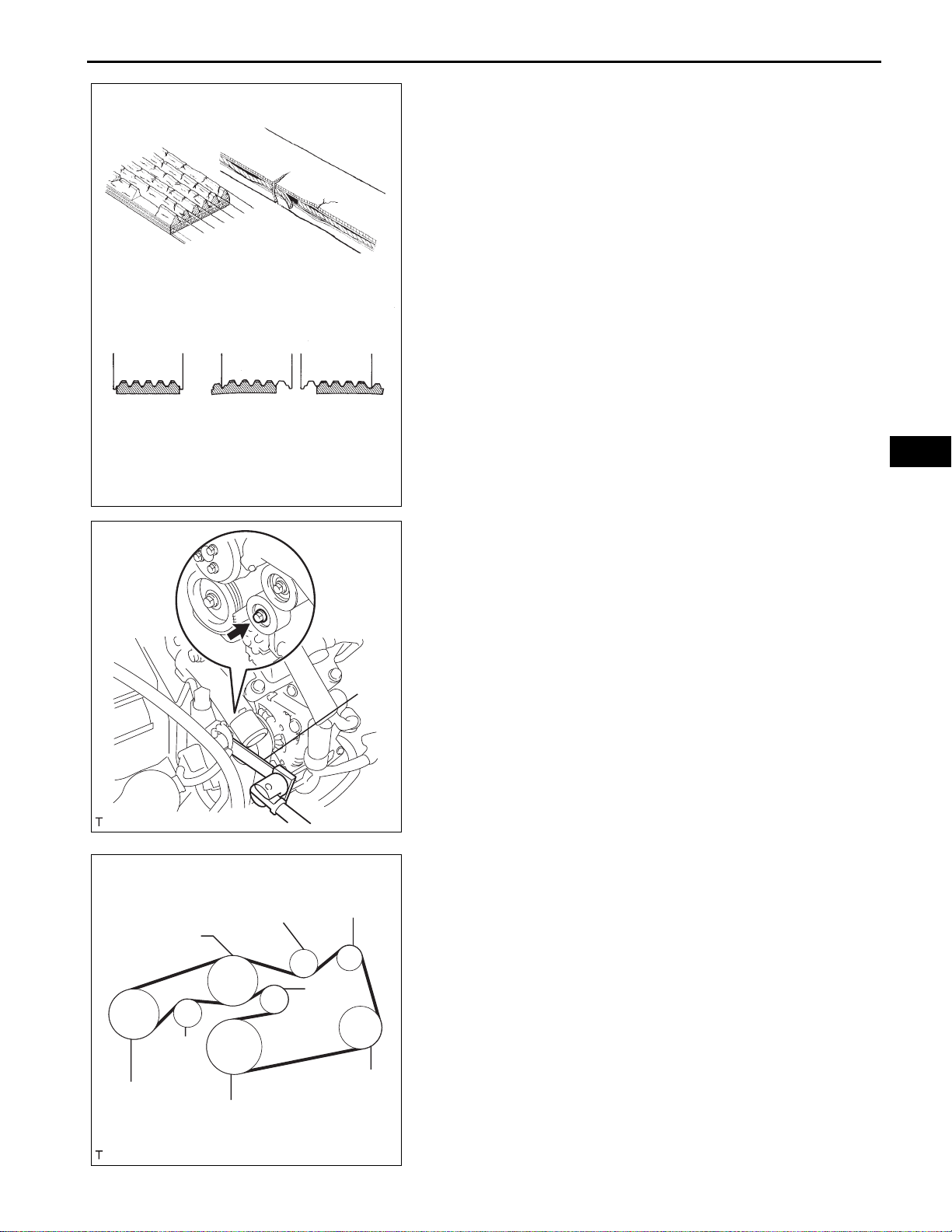
1. INSPECT V-RIBBED BELT
(a) Visually check the V-ribbed belt for excessive wear,
frayed cords, etc.
If any defect has been found, replace the V-ribbed
belt.
HINT:
Cracks on the rib side of a V-ribbed belt are
considered acceptable.
If the drive belt has chunks missing from its ribs, it
should be replaced.
HINT:
• A "new belt" is a belt which has been used for
less than 5 minutes with the engine running.
• A "used belt" is a belt which has been used for 5
minutes or more with the engine running.
2. INSPECT V-RIBBED BELT TENSIONER ASSEMBLY
(a) Check that nothing gets caught in the tensioner by
turning it clockwise and counterclockwise.
If a malfunction exitsts, replace the tensioner.
INSTALLATION
EM
Water Pump
Vane Pump
Idler
Crankshaft
Generator
Idler
Tensioner
A/C Compressor
SST
A129622E01
A129623E01
1. INSTALL V-RIBBED BELT
(a) Install the V-ribbed belt.
(b) Using SST, turn the belt tensioner counterclockwise
and remove the bar.
SST 09249-63010
(c) If it is difficult to install the V-ribbed belt, perform the
following procedure:
(1) Put the V-rib bed belt on every pulley except the
tensioner pulley as shown in the illustration.
(2) While releasing the belt tension by turning the
belt tensioner counterclockwise, put the Vribbed belt on the tensioner pulley.
NOTICE:
• Put the backside of the V-ribbed belt on
the tensioner pulley and idler pulley.
• Check that the V-ribbed belt is properly
set to each pulley.
(3) After installing the V-ribbed belt, check that it
fits properly in the ribbed grooves. Confirm that
the belt has not slipped out of the grooves on
the bottom of the crank pulley by hand.

EM
EM–8
2GR-FE ENGINE MECHANICAL – DRIVE BELT
2. INSTALL V-BANK COVER SUB-ASSEMBLY (See
page EM-52)
3. INSTALL FRONT FENDER APRON SEAL RH
4. INSTALL FRONT WHEEL RH
Torque: 103 N*m (1,050 kgf*cm, 76 ft.*lbf)
EM–8
ENGINE2GR-FE ENGINE MECHANICAL
2GR-FE ENGINE MECHANICAL – ENGINE FRONT OIL SEAL
ENGINE FRONT OIL SEAL
COMPONENTS
EM
250 (2,550, 184)
CRANKSHAFT PULLEY
TIMING CHAIN CASE OIL SEAL
V-BANK COVER SUB-ASSEMBLY
V-RIBBED BELT
FRONT FENDER APRON
SEAL RH
N*m (kgf*cm, ft.*lbf)
Non-reusable part
: Specified torque
A134932E01
SST
2GR-FE ENGINE MECHANICAL – ENGINE FRONT OIL SEAL
REMOVAL
1. REMOVE FRONT WHEEL RH
2. REMOVE FRONT FENDER APRON SEAL RH
3. REMOVE V-BANK COVER SUB-ASSEMBLY (See
page EM-23)
4. REMOVE V-RIBBED BELT (See page EM-6)
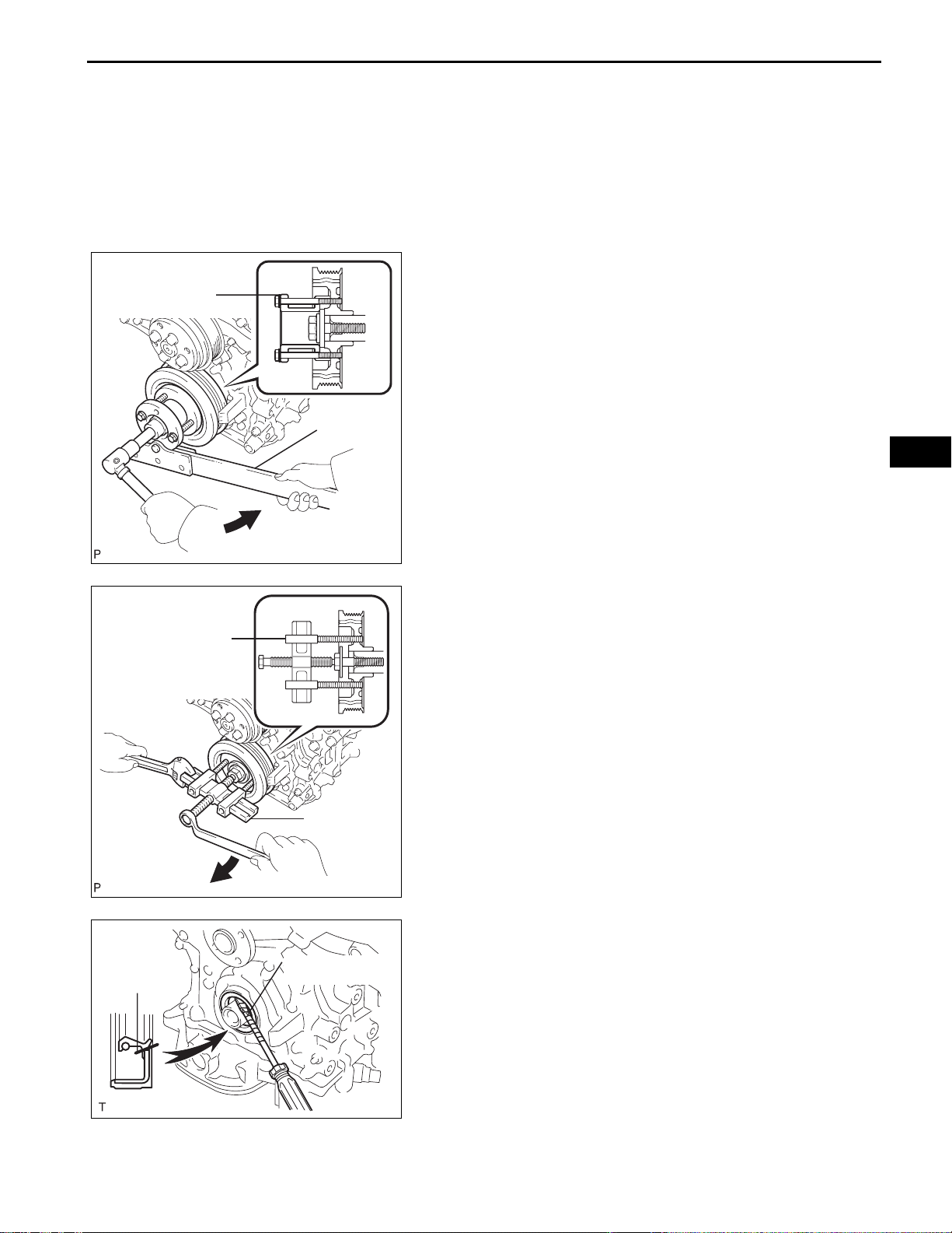
5. REMOVE CRANKSHAFT PULLEY
(a) Using SST, loosen the crankshaft pulley bolt.
SST 09213-70011 (09213-70020), 09330-00021
SST
EM–9
EM
Cut Position
SST
A119083E01
SST
A119085E01
Protective Tape
(b) Using SST, remove the crankshaft pulley bolt and
crankshaft pulley.
SST 09950-50013 (09951-05010, 09952-05010,
09953-05020, 09954-05021)
6. REMOVE TIMING CHAIN CASE OIL SEAL
(a) Using a screwdriver, pry out the oil seal.
HINT:
Tape the screwdriver tip before use.
NOTICE:
After the removal, check the crankshaft for
damage. If it is damaged, smooth the surface
with 400-grit sandpaper.
A132241E01
EM–10
2GR-FE ENGINE MECHANICAL – ENGINE FRONT OIL SEAL
EM
Chain Cover
SST
A132242E01
INSTALLATION
1. INSTALL TIMING CHAIN CASE OIL SEAL
(a) Apply MP grease to a new oil seal lip.
(b) Using SST and a hammer , ta p in the oil seal until it s
surface is flush with the timing chain cover edge.
SST 09316-60011 (09316-00011)
NOTICE:
• Keep the lip free of foreign matter.
• Do not tap the oil seal at an angle.
2. INSTALL CRANKSHAFT PULLEY
(a) Align the pulley set key with the key groove of the
pulley, and slide on the pulley.
(b) Using SST, install the pulley bolt.
SST 09213-70011 (09213-70020), 09330-00021
Torque: 250 N*m (2,550 kgf*cm, 184 ft.*lbf)
3. INSTALL V-RIBBED BELT (See page EM-7)
4. INSTALL V-BANK COVER SUB-ASSEMBLY (See
page EM-52)
5. INSTALL FRONT FENDER APRON SEAL RH
6. INSTALL FRONT WHEEL RH
Torque: 103 N*m (1,050 kgf*cm, 76 ft.*lbf)
SST
A119084E01
2GR-FE ENGINE MECHANICAL – ENGINE REAR OIL SEAL
ENGINE2GR-FE ENGINE MECHANICAL
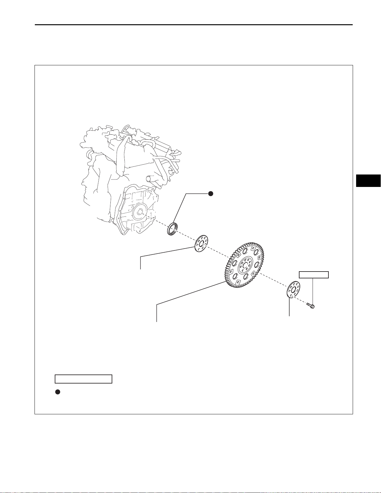
ENGINE REAR OIL SEAL
COMPONENTS
EM–11
EM
ENGINE REAR OIL SEAL
DRIVE PLATE AND RING GEAR SUB-ASSEMBLY
N*m (kgf*cm, ft.*lbf)
Non-reusable part
FRONT SPACER
: Specified torque
83 (850, 61)
x8
REAR SPACER
A134930E01
EM
EM–12
SST
2GR-FE ENGINE MECHANICAL – ENGINE REAR OIL SEAL
REMOVAL
1. REMOVE AUTOMATIC TRAN SAXLE ASSEMBLY
HINT:
See page AX-207.
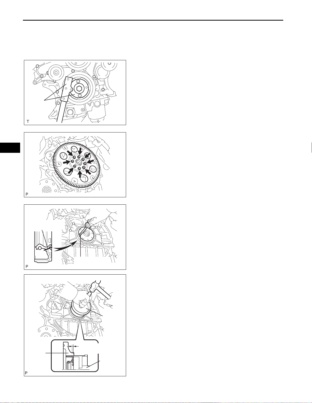
2. REMOVE DRIVE PLATE AND RING GEAR SUBASSEMBLY
(a) Using SST, hold the crankshaft.
SST 09213-70011 (09213-70020), 09330-00021
A129631E01
(b) Remove the 8 bolts, front spacer, drive plate and
rear spacer.
Cut Position
Protective Tape
SST
A132243
3. REMOVE ENGINE REAR OIL SEAL
(a) Using a knife, cut off the oil seal lip.
(b) Using a screwdriver, pry out the oil seal.
NOTICE:
Be careful not to damage the crankshaft. Tape
the screwdriver tip before use.
A132244E01
INSTALLATION
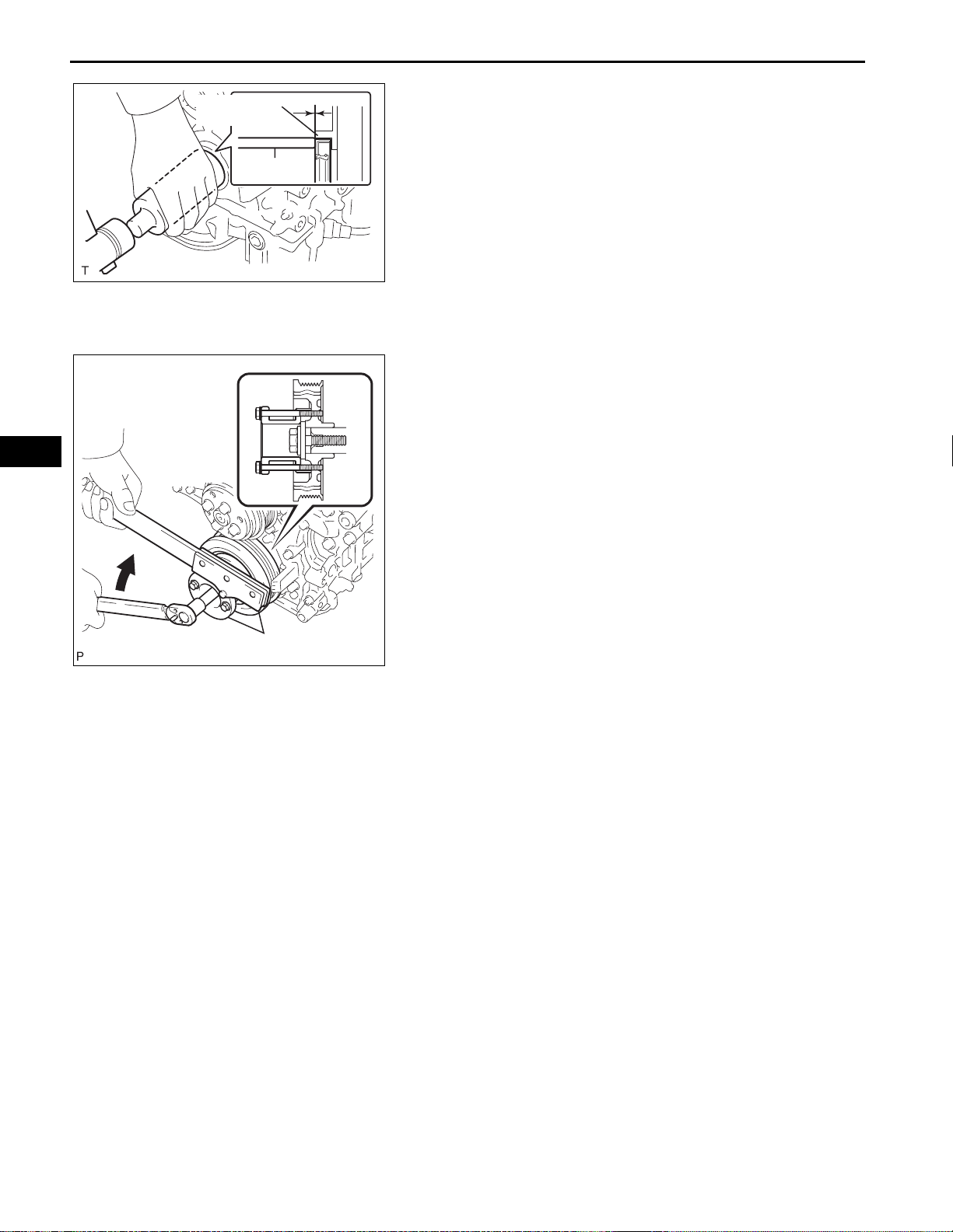
1. INSTALL ENGINE REAR OIL SEAL
(a) Apply MP grease to a new oil seal lip.
(b) Using SST and a hammer, tap in the oil seal.
SST 09223-15030, 09950-70010 (09951-07150)
Oil seal tap in depth:
-0.5 to 0.5 mm (-0.020 to 0.020 in.)
Retainer
-0.5 to 0.5 mm
SST
A132245E01
SST
2GR-FE ENGINE MECHANICAL – ENGINE REAR OIL SEAL
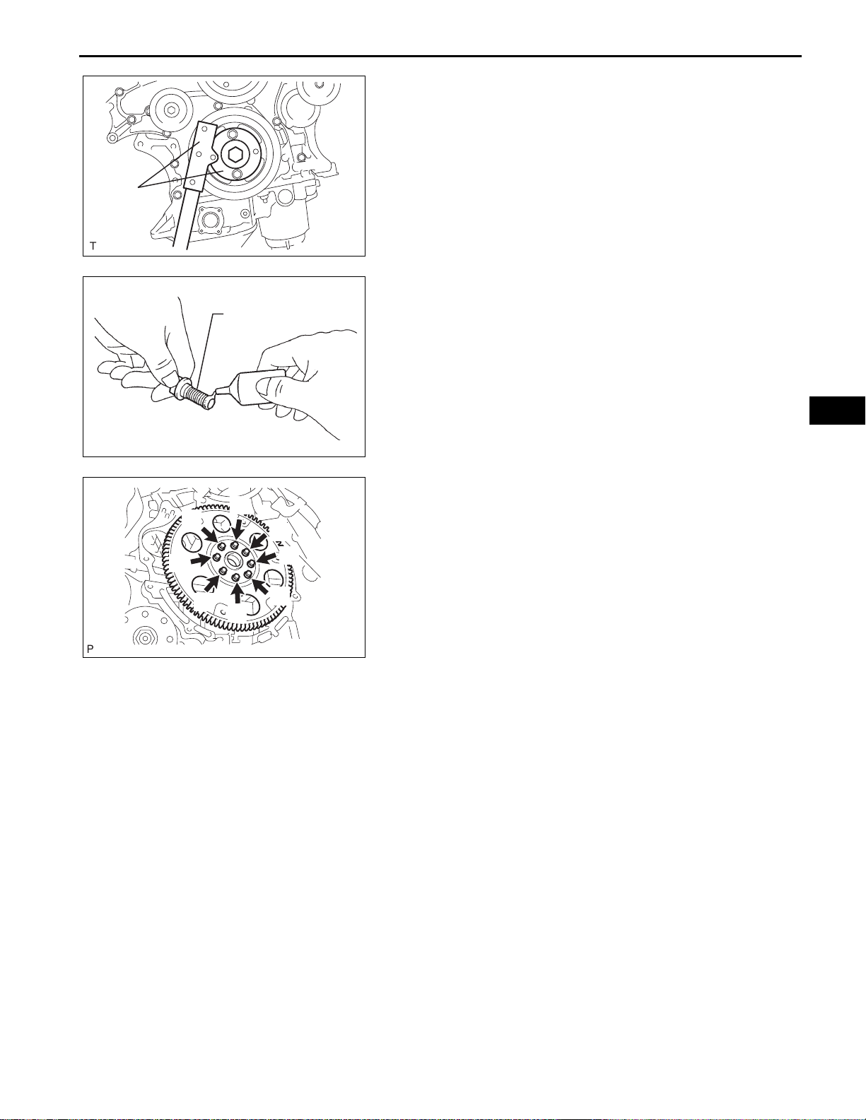
2. INSTALL DRIVE PLATE AND RING GEAR SUBASSEMBLY
(a) Using SST, hold the crankshaft.
SST 09213-70011 (09213-70020), 09330-00021
A129631E01
(b) Apply adhesive to 2 or 3 threads of the mounting
bolt end.
Adhesive
Adhesive:
Part No. 08833-00070, THREE BOND 1324 or
equivalent
P000601E04
EM–13
EM
(1) Install the front spacer, drive plate and rear
5
3
1
7
4
spacer on the crankshaft.
(2) Install and tighten the 8 mounting bolts
uniformly in several steps.
Torque: 83 N*m (850 kgf*cm, 61 ft.*lbf)
3. INSTALL AUTOMATIC TRANSAXLE ASSEMBLY
8
6
2
A132243E01
HINT:
See page AX-214.
EM–14
ENGINE2GR-FE ENGINE MECHANICAL
2GR-FE ENGINE MECHANICAL – ENGINE ASSEMBLY
ENGINE ASSEMBLY
COMPONENTS
EM
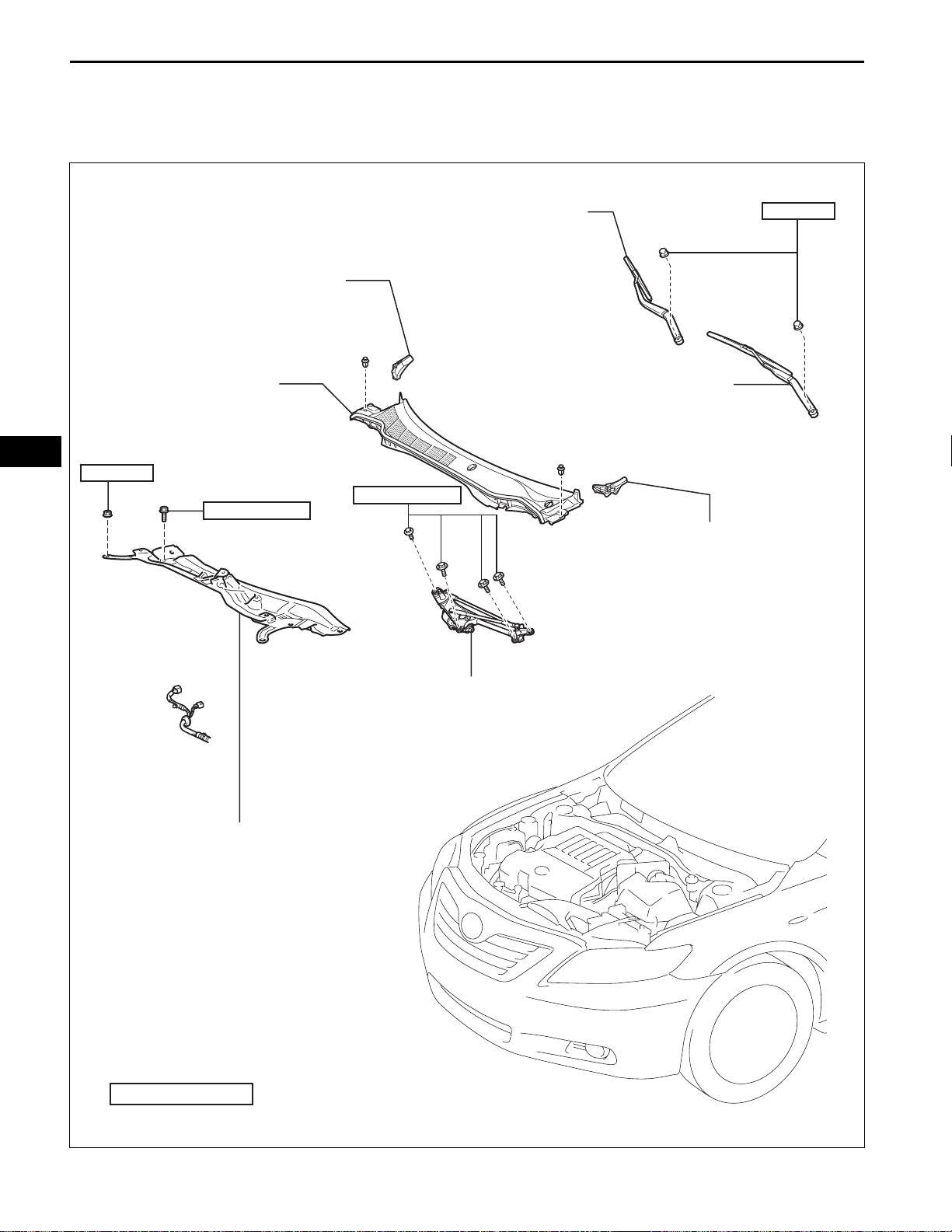
FRONT FENDER TO COWL
SIDE SEAL RH
COWL TOP VENTILATOR
LOUVER SUB-ASSEMBLY
85 (867, 63)
5.0 (51, 44 in.*lbf)
FRONT WIPER ARM AND
BLADE ASSEMBLY RH
7.5 (77, 66 in.*lbf)
20 (204, 15)
FRONT WIPER ARM AND
BLADE ASSEMBLY LH
FRONT FENDER TO COWL
SIDE SEAL LH
COWL TOP PANEL OUTER SUB-ASSEMBLY
N*m (kgf*cm, ft.*lbf)
: Specified torque
WINDSHIELD WIPER
LINK ASSEMBLY
A134938E01
2GR-FE ENGINE MECHANICAL – ENGINE ASSEMBLY
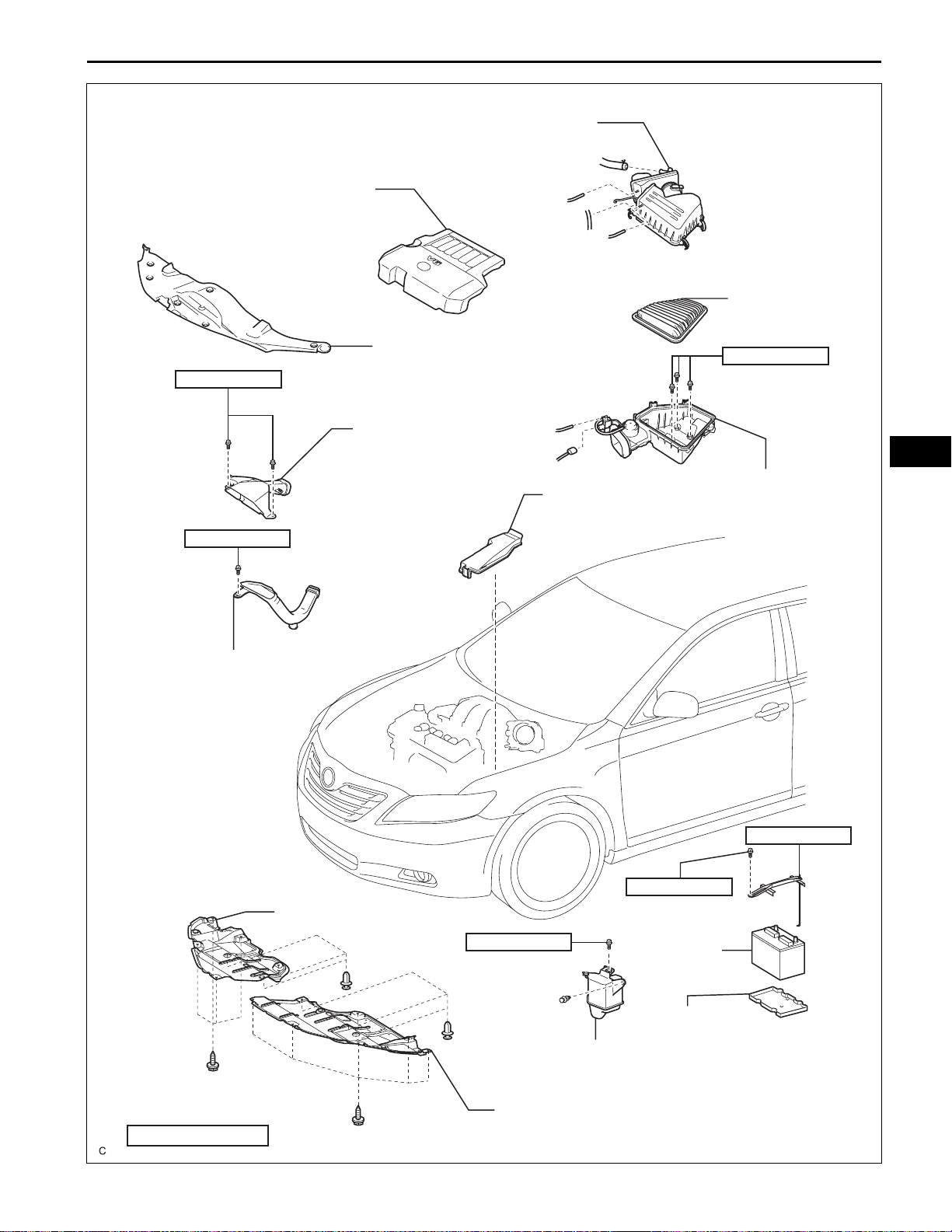
AIR CLEANER CAP SUB-ASSEMBLY
V-BANK COVER SUB-ASSEMBLY
EM–15
AIR CLEANER
FILTER ELEMENT
5.0 (51, 44 in.*lbf)
5.0 (51, 44 in.*lbf)
NO. 1 AIR CLEANER INLET
COOL AIR INTAKE DUCT SEAL
AIR CLEANER INLET
ASSEMBLY
RELAY BLOCK
COVER UPPER
5.0 (51, 44 in.*lbf)
EM
AIR CLEANER CASE
SUB-ASSEMBLY
N*m (kgf*cm, ft.*lbf)
ENGINE UNDER COVER RH
: Specified torque
5.0 (51, 44 in.*lbf)
INTAKE AIR RESONATOR
SUB-ASSEMBLY
ENGINE UNDER COVER LH
3.5 (36, 31 in.*lbf)
9.0 (92, 80 in.*lbf)
BATTERY
BATTERY TRAY
A132994E01
EM–16
2GR-FE ENGINE MECHANICAL – ENGINE ASSEMBLY
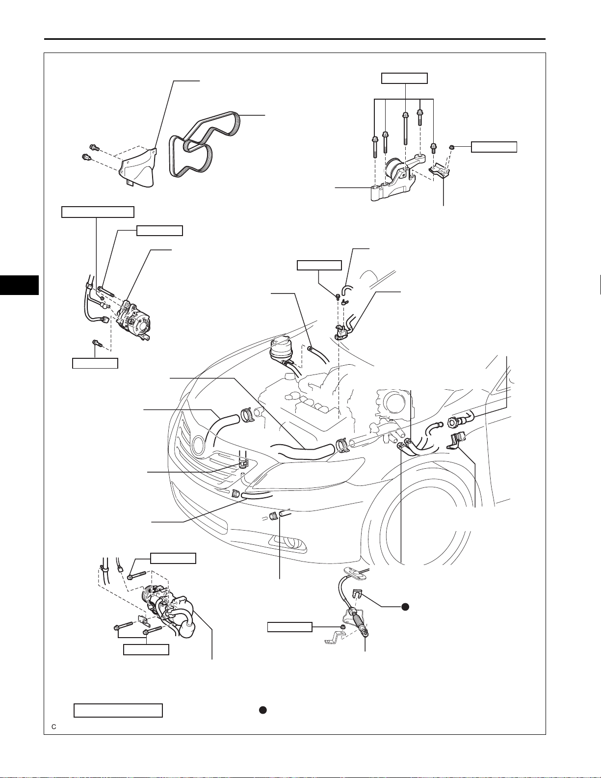
EM
9.8 (100, 87 in.*lbf)
FRONT FENDER APRON SEAL RH
ENGINE MOVING CONTROL
ROD SUB-ASSEMBLY
43 (438, 32)
GENERATOR ASSEMBLY
NO. 1 OIL RESERVOIR
TO PUMP HOSE
38 (388, 28)
V-RIBBED BELT
23 (235, 17)
NO. 2 ENGINE MOUNTING STAY RH
NO. 1 FUEL VAPOR FEED HOSE
10 (102, 7)
NO. 1 VACUUM SWITCHING
VALVE ASSEMBLY
FUEL TUBE SUB-ASSEMBLY
43 (438, 32)
RADIATOR HOSE INLET
RADIATOR HOSE
OUTLET
RETURN TUBE
SUB-ASSEMBLY
NO. 1 OIL COOLER
INLET HOSE
25 (250, 18)
HEATER INLET WATER HOSE
NO. 1 FUEL PIPE CLAMP
HEATER OUTLET WATER HOSE
NO. 1 OIL COOLER
OUTLET HOSE
CLIP
13 (130, 9)
25 (250, 18)
COOLER COMPRESSOR ASSEMBLY
N*m (kgf*cm, ft.*lbf)
: Specified torque
TRANSMISSION CONTROL
CABLE ASSEMBLY
Non-reusable part
A132995E01
STEERING SLIDING YOKE
35 (360, 26)
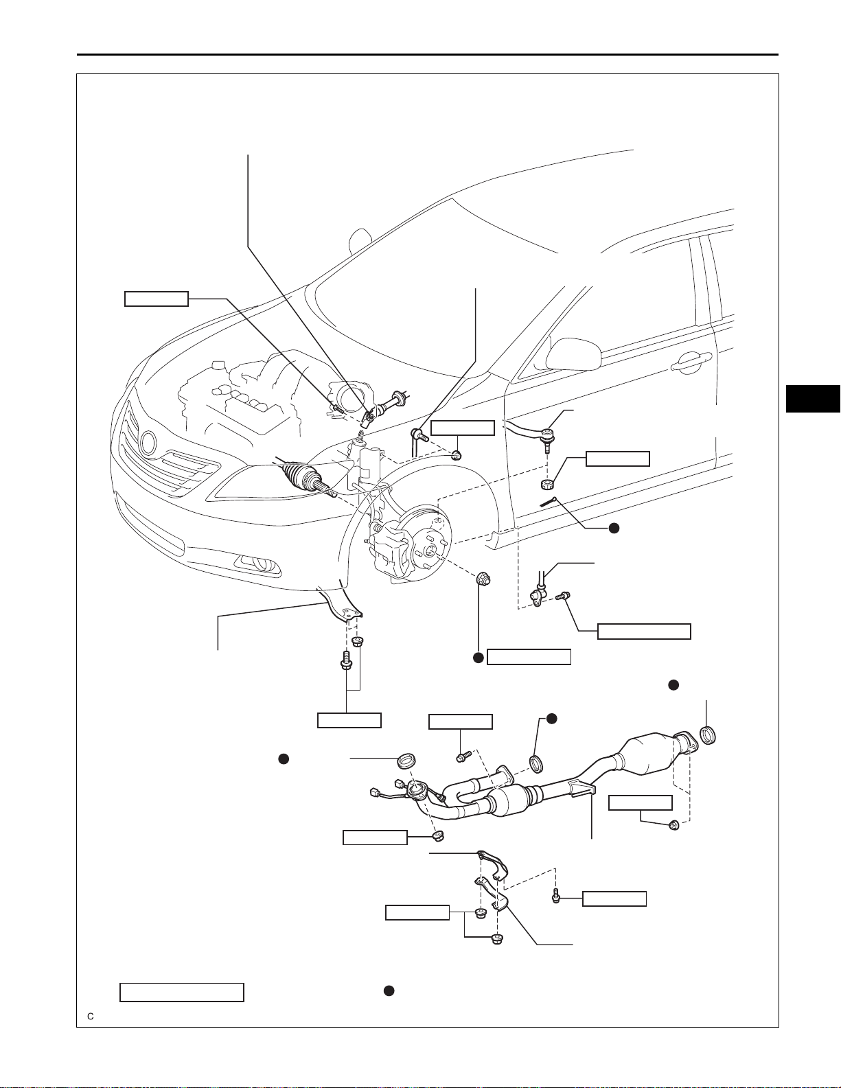
2GR-FE ENGINE MECHANICAL – ENGINE ASSEMBLY
FRONT STABILIZER LINK ASSEMBLY LH
EM–17
FRONT SUSPENSION
LOWER NO. 1 ARM LH
75 (765, 55)
GASKET
74 (755, 55)
62 (632, 46)
TIE ROD ASSEMBLY LH
49 (500, 36)
COTTER PIN
FRONT SPEED
SENSOR LH
8.0 (85, 71 in.*lbf)
294 (3,000, 217)
FRONT AXLE HUB NUT LH
GASKET
56 (571, 41)
EM
GASKET
62 (632, 46)
NO. 1 EXHAUST PIPE SUPPORT BRACKET
N*m (kgf*cm, ft.*lbf)
: Specified torque
EXHAUST PIPE ASSEMBLY FRONT
21 (214, 15)
33 (337, 24)
EXHAUST PIPE NO. 1
SUPPORT BRACKET
Non-reusable part
A132996E01
EM–18
2GR-FE ENGINE MECHANICAL – ENGINE ASSEMBLY
EM
95 (969, 70)
87 (887, 64)
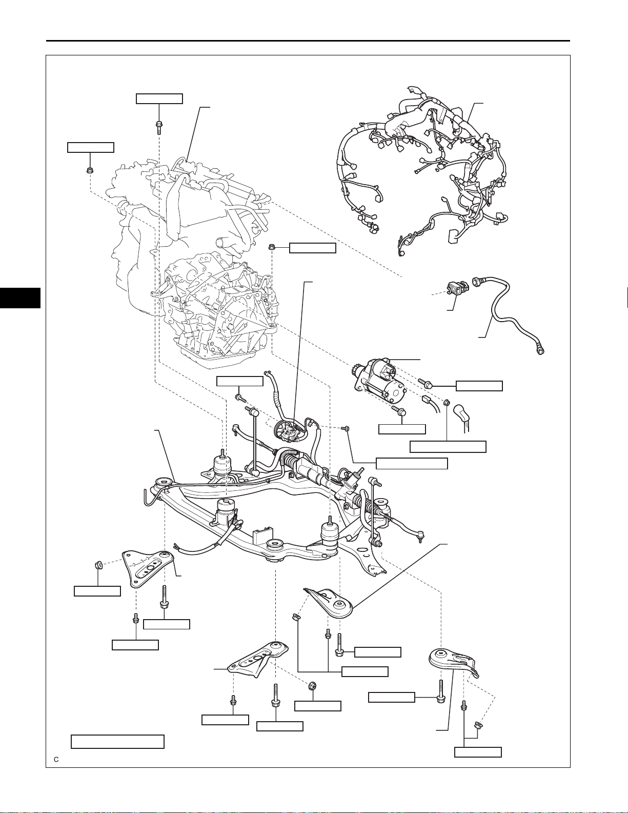
ENGINE ASSEMBLY
WITH TRANSAXLE
95 (969, 70)
43 (439, 32)
ENGINE WIRE
VANE PUMP ASSEMBLY
NO. 2 FUEL PIPE CLAMP
FUEL TUBE SUB-ASSEMBLY
STARTER ASSEMBLY
37 (380, 26)
FRONT FRAME
ASSEMBLY
FRAME SIDE RAIL
32 (329, 24)
85 (867, 63)
32 (329, 24)
PLATE RH
FRAME SIDE RAIL PLATE LH
N*m (kgf*cm, ft.*lbf)
: Specified torque
32 (329, 24)
85 (867, 63)
37 (380, 26)
7.8 (80, 69 in.*lbf)
85 (867, 63)
32 (329, 24)
85 (867, 63)
32 (329, 24)
FRONT SUSPENSION
MEMBER BRACE REAR LH
9.8 (100, 87 in.*lbf)
FRONT SUSPENSION
MEMBER BRACE
REAR RH
32 (329, 24)
A134929E01

2GR-FE ENGINE MECHANICAL – ENGINE ASSEMBLY
54 (551, 40)
ENGINE MOUNTING BRACKET RH
DRIVE SHAFT BEARING BRACKET HOLE SNAP RING
EM–19
FRONT DRIVE SHAFT
ASSEMBLY RH
NO. 1 DRIVE SHAFT BEARING
BRACKET SETTING BOLT
32 (334, 30)
DRIVE SHAFT BEARING BRACKET
64 (650, 47)
EM
FRONT DRIVE SHAFT INNER
LH SHAFT SNAP RING
46 (469, 34)
FRONT DRIVE SHAFT ASSEMBLY LH
7.8 (80, 69 in.*lbf)
FLYWHEEL HOUSING
UNDER COVER
64 (653, 47)
43 (438, 32)
64 (653, 47)
41 (413, 30)
DRIVE PLATE AND TORQUE
CONVERTER CLUTCH
SETTING BOLT
N*m (kgf*cm, ft.*lbf)
: Specified torque
EXHAUST PIPE
SUPPORT BRACKET
AUTOMATIC TRANSAXLE
ASSEMBLY
ENGINE MOUNTING BRACKET FR
Non-reusable part
A134940E01
EM–20
2GR-FE ENGINE MECHANICAL – ENGINE ASSEMBLY
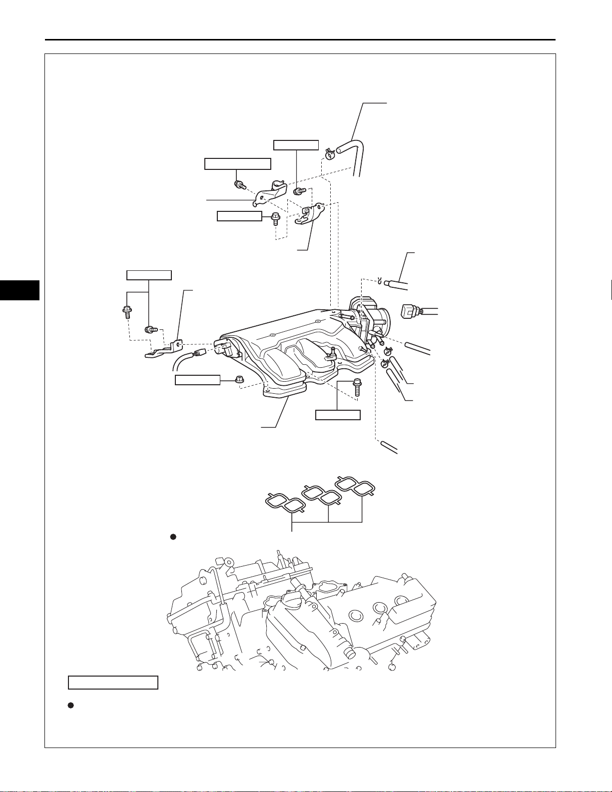
VACUUM HOSE CLAMP
5.4 (55, 48 in.*lbf)
21 (214, 15)
*
21 (214, 15)
*
UNION TO CHECK VALVE HOSE
EM
THROTTLE BODY BRACKET
21 (214, 15)
*
NO. 1 SURGE TANK STAY
16 (163, 12)
INTAKE AIR SURGE TANK
AIR SURGE TANK TO INTAKE MANIFOLD GASKET
18 (184, 13)
*
x4
VENTILATION HOSE
NO. 3 WATER BY-PASS HOSE
NO. 2 WATER BY-PASS HOSE
N*m (kgf*cm, ft.*lbf)
Non-reusable part
* DO NOT apply oil
: Specified torque
A134939E01
EXHAUST MANIFOLD
TO HEAD GASKET
21 (214, 15)
x6
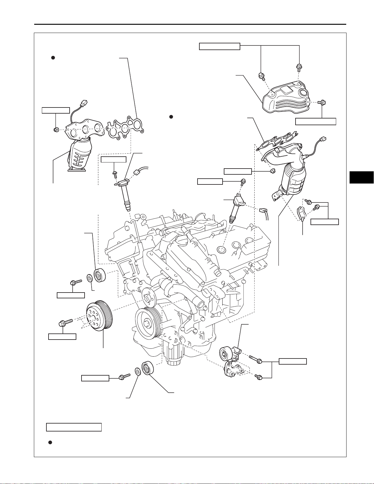
2GR-FE ENGINE MECHANICAL – ENGINE ASSEMBLY
8.5 (87, 75 in.*lbf)
NO. 2 EXHAUST MANIFOLD
HEAT INSULATOR
EXHAUST MANIFOLD TO
HEAD LH GASKET
EM–21
8.5 (87, 75 in.*lbf)
EXHAUST MANIFOLD
SUB-ASSEMBLY RH
NO. 2 IDLER
PULLEY SUBASSEMBLY (RR
SIDE)
43 (438, 32)
21 (214, 15)
PLATE
10 (102, 7)
IGNITION COIL ASSEMBLY
10 (102, 7)
IGNITION COIL ASSEMBLY
21 (214, 15)
x6
EM
34 (347, 25)
NO. 2 MANIFOLD
STAY
EXHAUST MANIFOLD
SUB-ASSEMBLY LH
V-RIBBED BELT TENSIONER
ASSEMBLY
WATER PUMP PULLEY
43 (438, 32)
N*m (kgf*cm, ft.*lbf)
Non-reusable part
PLATE
: Specified torque
43 (438, 32)
NO. 2 IDLER PULLEY
SUB-ASSEMBLY (FR SIDE)
A134941E01
EM–22
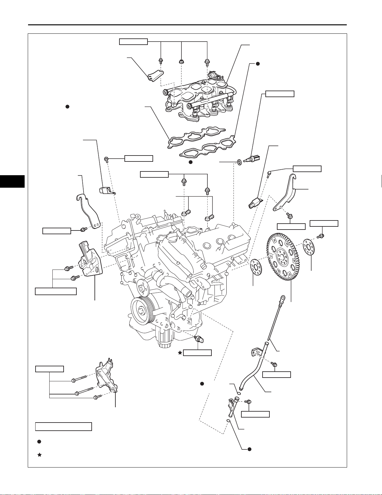
2GR-FE ENGINE MECHANICAL – ENGINE ASSEMBLY
EM
NO. 2 ENGINE MOUNTING
STAY RH
NO. 1 INTAKE MANIFOLD
TO HEAD GASKET
RADIO SETTING
CONDENSER
NO. 1 ENGINE
HANGER
21 (214, 15)
10 (102, 7)
20 (204, 15)
KNOCK CONTROL
SENSOR
x4
GASKET
x6
INTAKE MANIFOLD
NO. 2 INTAKE MANIFOLD
TO HEAD GASKET
20 (200, 14)
ENGINE COOLANT
TEMPERATURE
SENSOR
RADIO SETTING
CONDENSER
10 (102, 7)
NO. 2
ENGINE
HANGER
33 (337, 24)
6.0 (61, 53 in.*lbf)
NO. 2 TIMING GEAR COVER
ENGINE OIL PRESSURE
54 (551, 40)
SWITCH ASSEMBLY
x3
x2
NO. 1 ENGINE MOUNTING BRACKET FRONT LH
21 (214, 15)
O-RING
DRIVE PLATE
SPACER FRONT
21 (214, 15)
NO. 2 OIL LEVEL
GAUGE GUIDE
21 (214, 15)
33 (337, 24)
83 (846, 61)
x8
DRIVE PLATE
SPACER REAR
DRIVE PLATE
AND RING GEAR
SUB-ASSEMBLY
OIL LEVEL GAUGE
N*m (kgf*cm, ft.*lbf)
Non-reusable part
Precoated Part
: Specified torque
NO. 1 OIL LEVEL GAUGE GUIDE
O-RING
A134942E01
2GR-FE ENGINE MECHANICAL – ENGINE ASSEMBLY
REMOVAL
1. DISCHARGE FUEL SYSTEM PRESSURE
HINT:
See page FU-1.
2. DISCONNECT CABLE FROM NEGATIVE BATTERY
TERMINAL
3. PLACE FRONT WHEELS FACING STRAIGHT AHEAD
4. REMOVE FRONT WHEELS
5. REMOVE ENGINE UNDER COVER LH
6. REMOVE ENGINE UNDER COVER RH
7. REMOVE FRONT FENDER APRON SEAL RH
8. DRAIN ENGINE OIL (See page LU-4)
9. DRAIN ENGINE COOLANT (See page CO-5)
EM–23
A132967
A132968
10. DRAIN AUTOMATIC TRANSAXLE FLUID (See page
AX-207)
11. REMOVE WINDSHIELD WIPER LINK ASSEMBLY
See page WW-9.
12. REMOVE COWL TOP PANEL OUTER SUBASSEMBLY (See page ES-481)
13. REMOVE COOL AIR INTAKE DUCT SEAL
(a) Remove the 7 clips and intake duct seal.
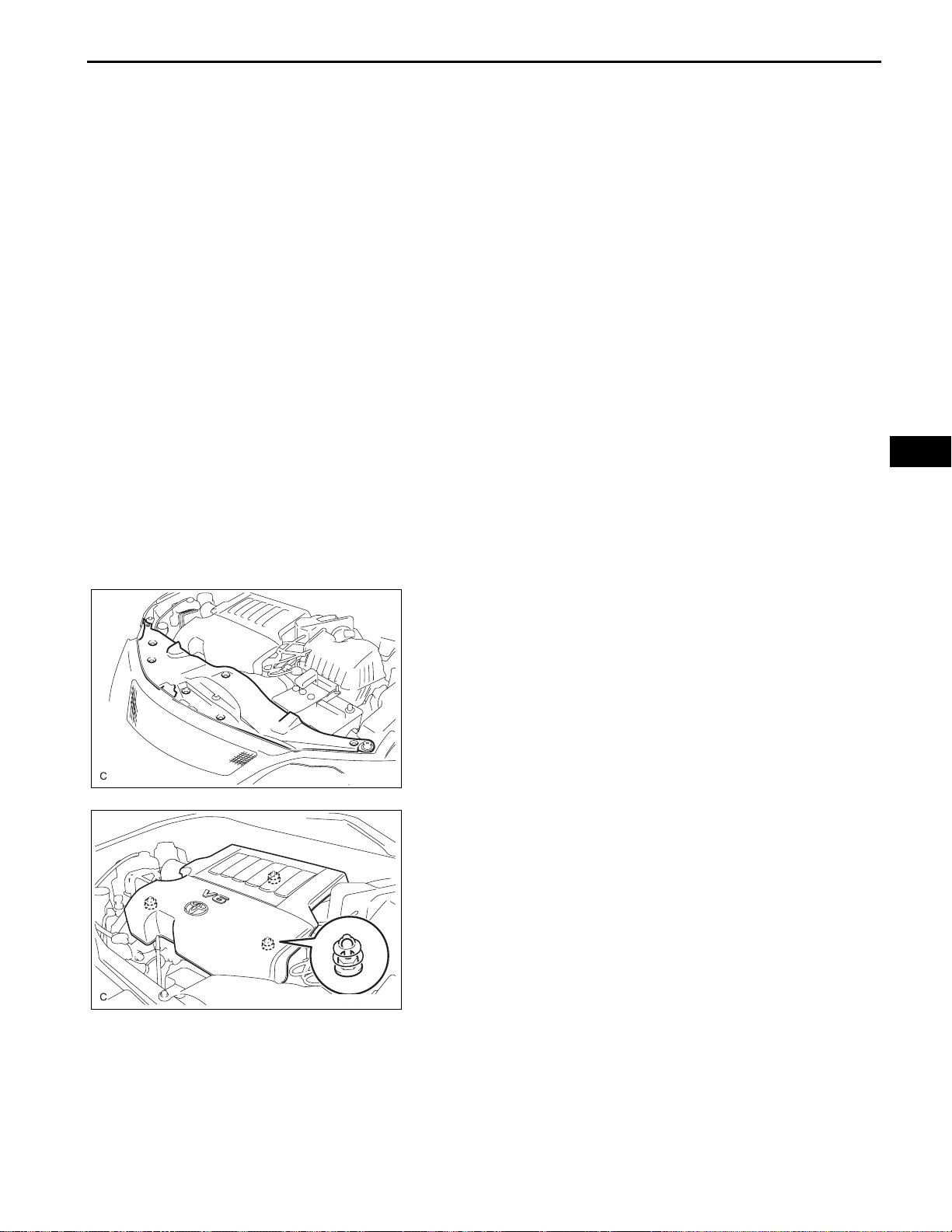
14. REMOVE V-BANK COVER SUB-ASSEMBLY
(a) Hold the front of the V-bank cover and raise it to
disengage the 2 clips on the front of the cover.
Continue to raise the cover to disengage the clip on
the rear of the cover and remove the cover.
NOTICE:
Attempting to disengage both front and rear
clips at the same time may cause the cover to
break.
15. REMOVE V-RIBBED BELT (See page EM-6)
EM
EM
EM–24
2GR-FE ENGINE MECHANICAL – ENGINE ASSEMBLY
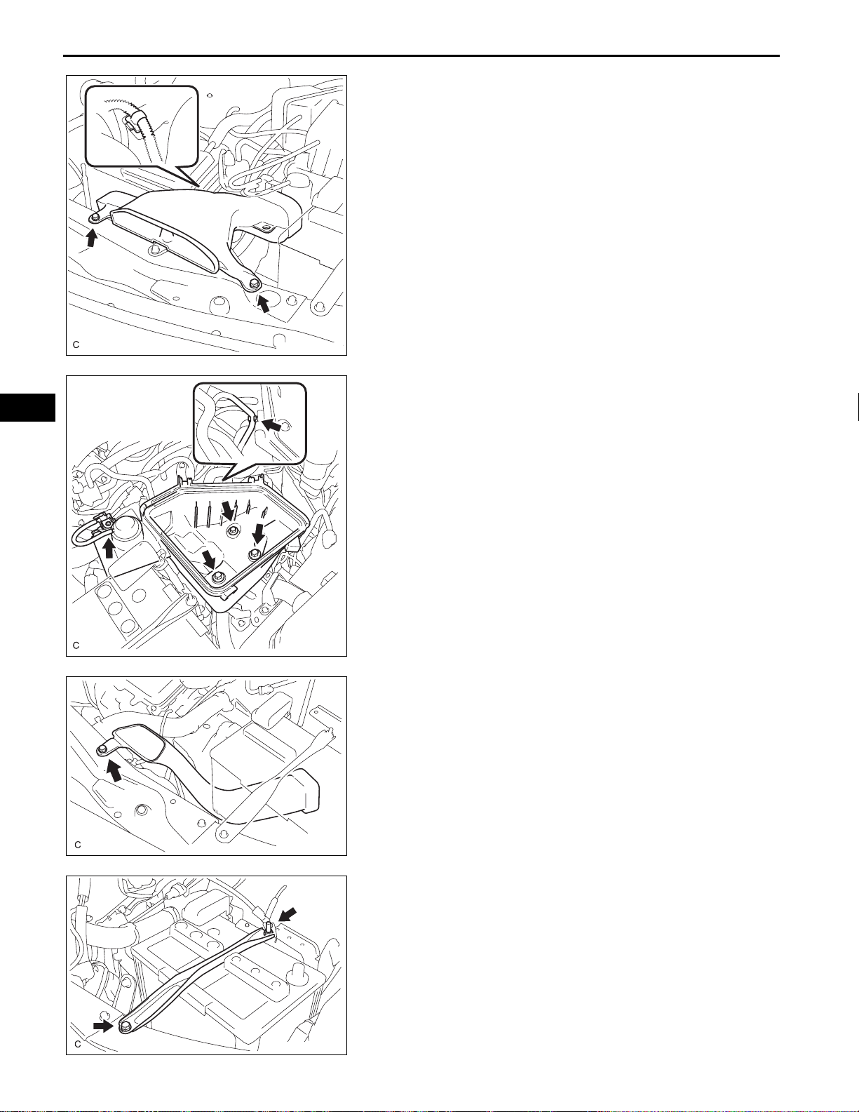
16. REMOVE AIR CLEANER INLET ASSEMBLY
(a) Remove the 2 bolts, clamp and air cleaner inlet.
17. REMOVE AIR CLEANER CAP SUB-ASSEMBLY (See
page ES-503)
A132969
18. REMOVE AIR CLEANER CASE SUB-ASSEMBLY
(a) Disconnect the vacuum hose and hose clamp.
(b) Remove the 3 bolts and air cleaner case.
A132971
A132970
A132972
19. REMOVE NO. 1 AIR CLEANER INLET
(a) Remove the bolt and No. 1 air cleaner inlet.
20. REMOVE BATTERY
(a) Loosen the bolt and nut, and remove the battery
clamp.
(b) Remove the battery and battery tray.
2GR-FE ENGINE MECHANICAL – ENGINE ASSEMBLY
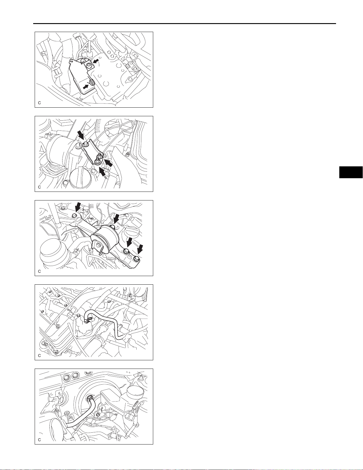
21. REMOVE INTAKE AIR RESONATOR SUB-ASSEMBLY
(a) Remove the clip, bolt and intake air resonator.
A133928
22. REMOVE NO. 2 ENGINE MOUNTING STAY RH
(a) Remove the bolt, 2 nuts, and No. 2 mounting stay
RH.
A132985
EM–25
EM
A132986
A132983
23. REMOVE ENGINE MOVING CONTROL ROD SUBASSEMBLY
(a) Remove the 4 bolts and engine moving control rod.
24. DISCONNECT NO. 1 FUEL VAPOR FEED HOSE
(a) Remove the clamp and disconnect the No. 1 fuel
vapor feed hose.
25. DISCONNECT CHECK VALVE TO BRAKE BOOSTER
HOSE
(a) Remove the clamp and disconnect the check valve
to brake booster hose.
A132982
EM
EM–26
2GR-FE ENGINE MECHANICAL – ENGINE ASSEMBLY
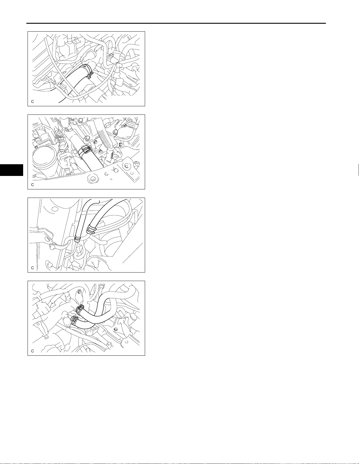
26. REMOVE RADIATOR HOSE INLET
(a) Remove the clamp and disconnect the radiator hose
inlet.
A132979
27. REMOVE RADIATOR HOSE OUTLET
(a) Remove the clamp and disconnect the radiator hose
outlet.
A132980
A133003
A132978
28. DISCONNECT NO. 1 OIL COOLER INLET HOSE
(a) Remove the clamp and disconnect the oil cooler
inlet hose.
29. DISCONNECT NO. 1 OIL COOLER OUTLET HOSE
(a) Remove the clamp and disconnect the oil cooler
outlet hose.
30. DISCONNECT HEATER INLET WATER HOSE
(a) Disconnect the heater inlet water hose.
31. DISCONNECT HEATER OUTLET WATER HOSE
(a) Disconnect the heater outlet water hose.
32. REMOVE ECM
HINT:
See page ES-518.
33. REMOVE RELAY BLOCK COVER UPPER
2GR-FE ENGINE MECHANICAL – ENGINE ASSEMBLY
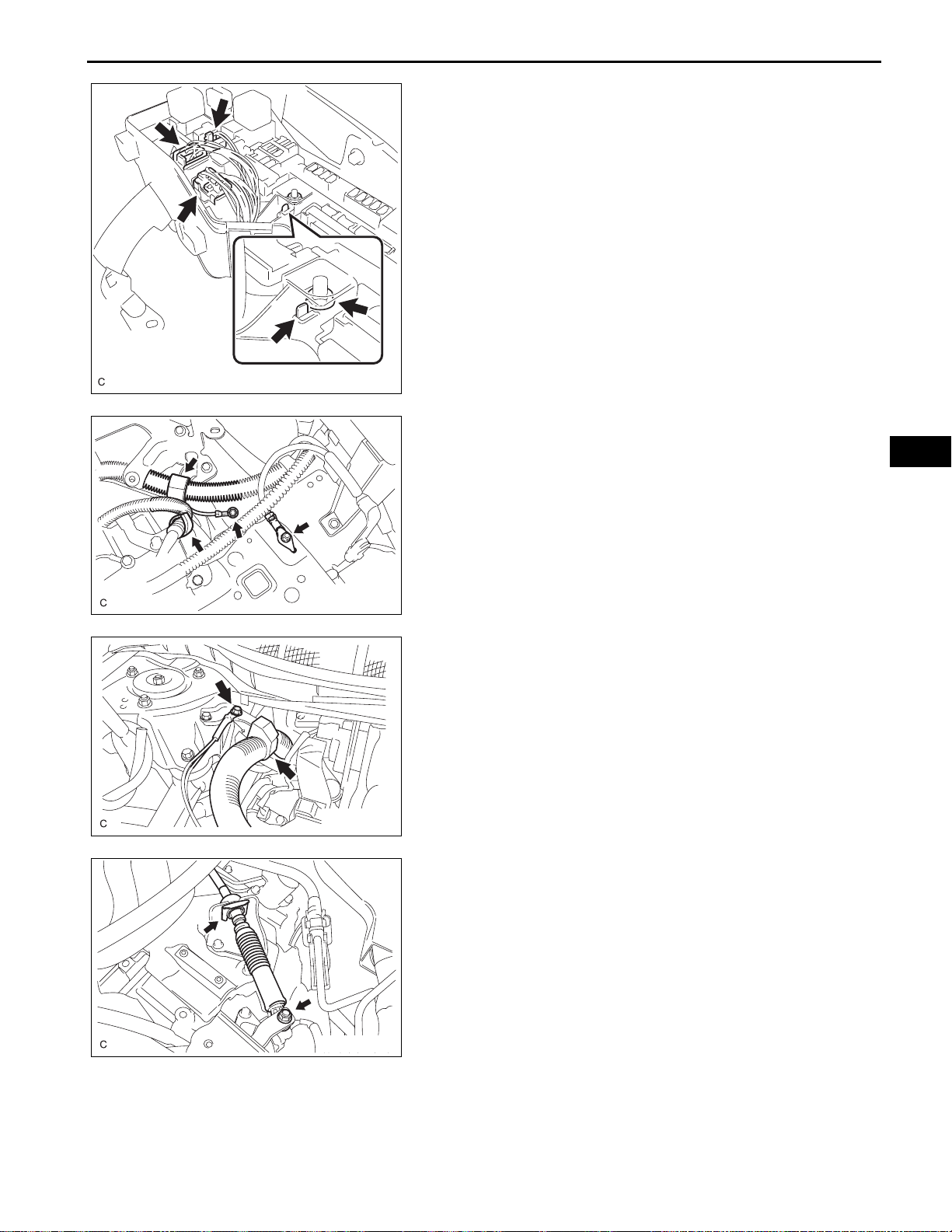
34. DISCONNECT ENGINE WIRE
(a) Disconnect the engine wire from the engine room
junction block.
(1) Remove the nut and separate the wire harness.
(2) Using a screwdriver, unlock the engine room J/
B. Pull the engine room J/B upward.
(3) Disconnect the engine wire connectors.
A132975
(b) Remove the 2 bolts and 2 clamps from the body.
EM–27
EM
A132976
A132981
A132973
(c) Remove the bolt and clamp from the bracket.
35. DISCONNECT TRANSMISSION CONTROL CABLE
ASSEMBLY
(a) Remove the clip and nut, and separate the cable
from the transaxle.
EM
EM–28
2GR-FE ENGINE MECHANICAL – ENGINE ASSEMBLY
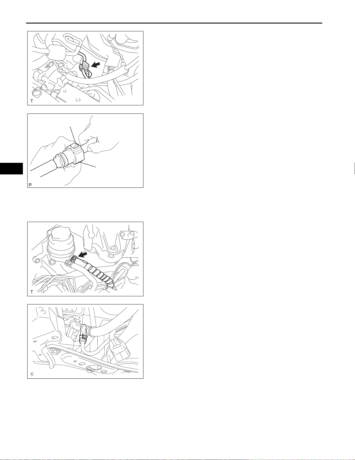
36. SEPARATE FUEL TUBE SUB-ASSEMBLY
(a) Remove the No. 1 fuel pipe clamp.
A129626
(b) Disconnect the connector from the tube while
A
pinching part A with your fingers as shown in the
illustration.
NOTICE:
• Check for contamination in the pipe and
around the connector . Clean if necessary and
then disconnect the connector.
A
• Disconnect the connector by hand.
• Do not bend, fold or rotate the nylon tube.
B012941E15
• If the pipe and connector are stuck together,
push and pull the connector until it becomes
free.
• Put the pipe and connector ends in vinyl bags
to prevent damage and contamination.
A129629
A132984
37. DISCONNECT NO. 1 OIL RESERVOIR TO PUMP
HOSE
(a) Disconnect the No. 1 oil reservoir to pump hose.
38. DISCONNECT RETURN TUBE SUB-ASSEMBLY
(a) Disconnect the return tube sub-assembly.
39. REMOVE EXHAUST PIPE NO. 1 SUPPORT BRACKET
(See page EX-3)
40. REMOVE EXHAUST PIPE ASSEMBLY FRONT (See
page EX-2)
41. REMOVE FRONT AXLE HUB NUT LH (See page DS-
7)
42. REMOVE FRONT AXLE HUB NUT RH
HINT:
Use the same procedures described for the LH side.
43. DISCONNECT FRONT STABILIZER LINK ASSEMBLY
LH (See page DS-7)
2GR-FE ENGINE MECHANICAL – ENGINE ASSEMBLY
44. DISCONNECT FRONT ST ABILIZER LINK ASSEMBLY
RH
HINT:
Use the same procedures described for the LH side.
45. DISCONNECT FRONT SPEED SENSOR LH (See page
DS-7)
46. DISCONNECT FRONT SPEED SENSOR RH
HINT:
Use the same procedures described for the LH side.
47. DISCONNECT TIE ROD ASSEMBLY LH (See page
DS-8)
48. DISCONNECT TIE ROD ASSEMBLY RH
HINT:
Use the same procedures described for the LH side.
49. DISCONNECT FRONT SUSPENSION LOWER NO. 1
ARM LH (See page DS-8)
50. DISCONNECT FRONT SUSPENSION LOWER NO. 1
ARM RH
HINT:
Use the same procedures described for the LH side.
EM–29
EM
51. SEPARATE FRONT AXLE ASSEMBLY LH (See page
DS-8)
52. SEPARATE FRONT AXLE ASSEMBLY RH
HINT:
Use the same procedures described for the LH side.
53. REMOVE NO. 1 EXHAUST PIPE SUPPORT BRACKET
(a) Remove the No. 1 exhaust pipe support bracket
with the 2 bolts.
54. REMOVE DRIVE PLATE AND TORQUE CONVERTER
CLUTCH SETTING BOLT (See page AX-211)
55. DISCONNECT STEERING SLIDING YOKE (See page
PS-40)
56. REMOVE GENERATOR ASSEMBLY (See page CH-14)
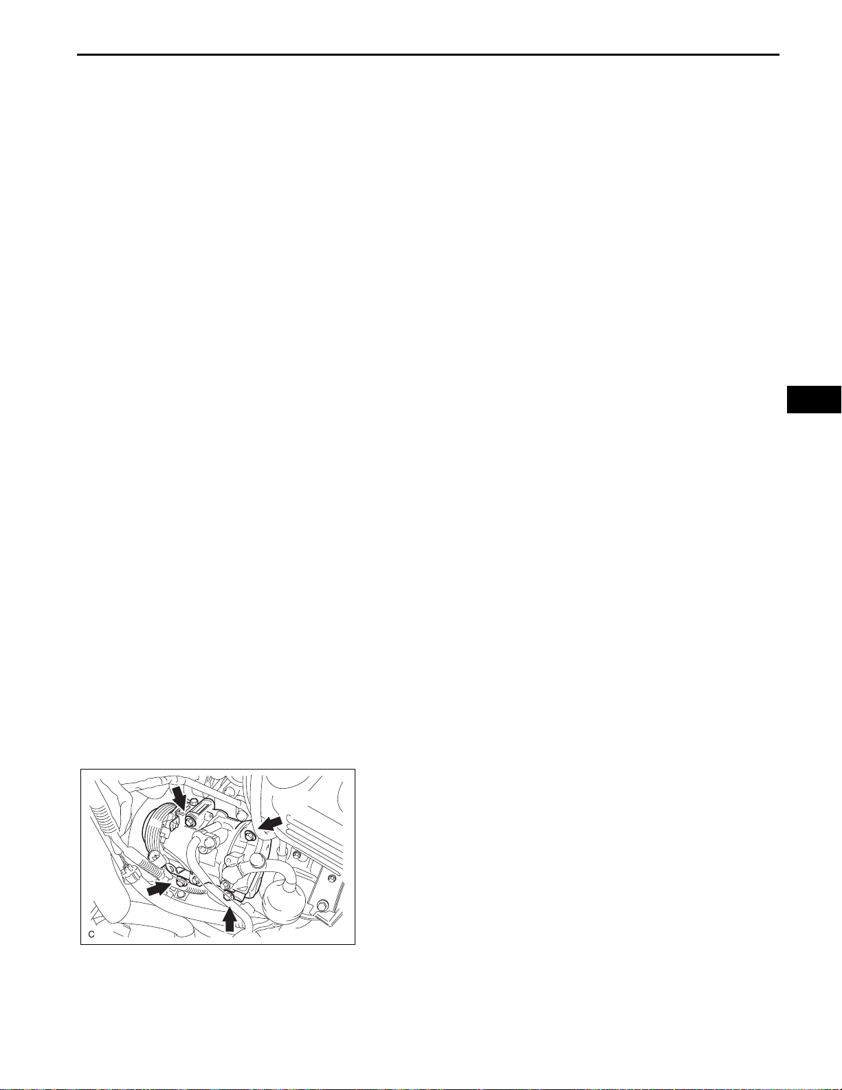
57. SEPARATE COOLER COMPRESSOR ASSEMBLY
(a) Remove the 2 connector clamps.
(b) Remove the 4 bolts and separate the compressor.
HINT:
Hang up the hoses instead of detaching them.
58. REMOVE ENGINE ASSEMBLY WITH TRANSAXLE
(a) Set the engine lifter.
A132977
 Loading...