

Toyota Camry 2007-2009 Service Manual - Air_Conditioning
Charging
Cylinder
AIR CONDITIONING – AIR CONDITIONING SYSTEM
AIR CONDITIONING SYSTEM
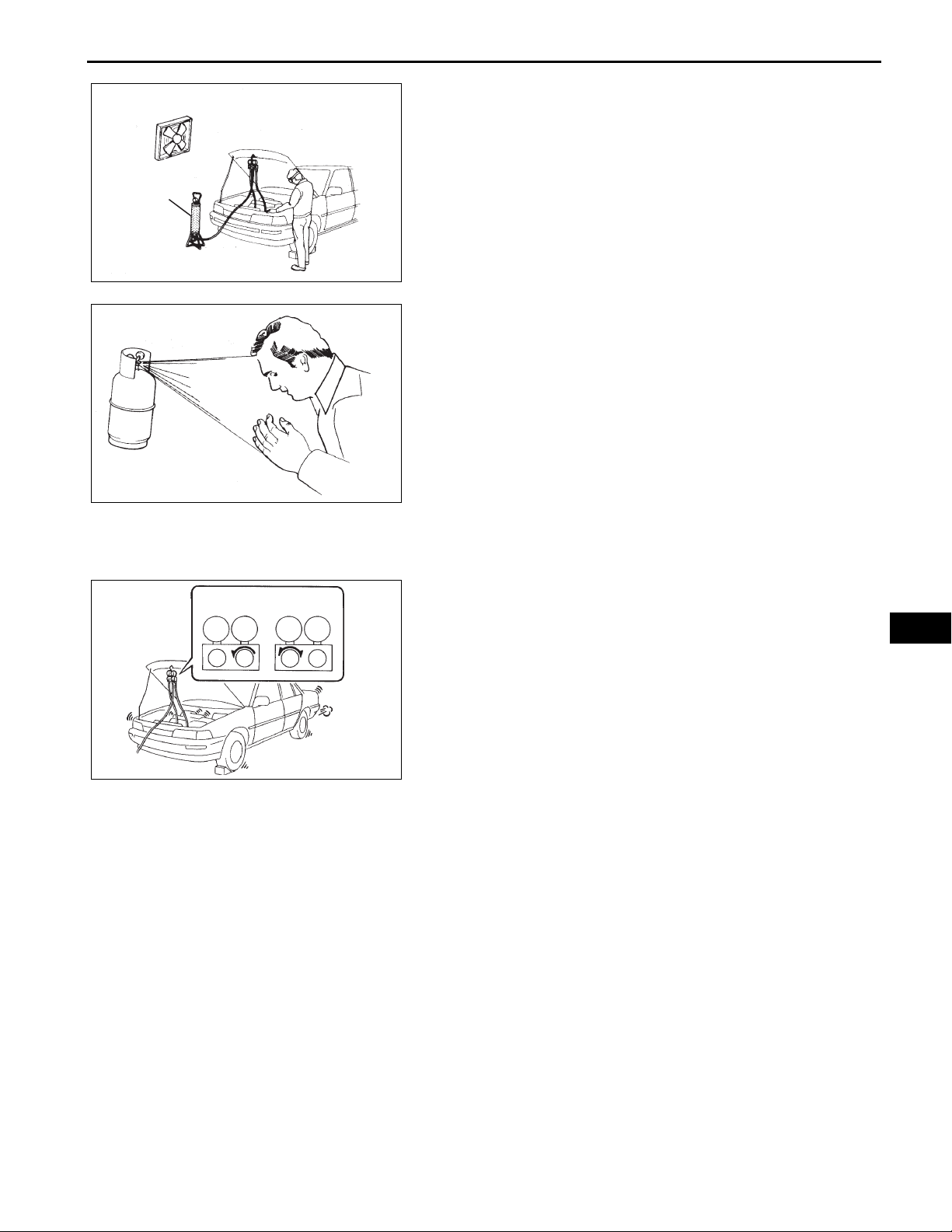
PRECAUTION
1. DO NOT HANDLE REFRIGERANT IN AN ENCLOSED
AREA OR NEAR AN OPEN FLAME
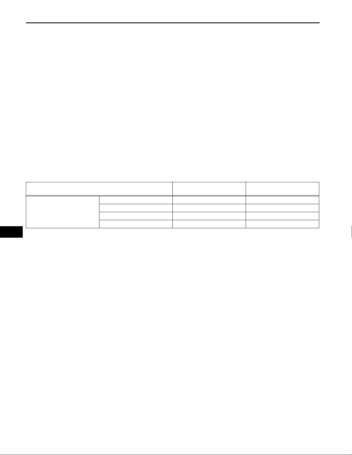
2. ALWAYS WEAR EYE PROTECTION
AC02810E02
3. BE CAREFUL NOT TO GET LIQUID REFRIGERANT
IN YOUR EYES OR ON YOUR SKIN
If liquid refrigerant gets in your eyes or on your skin:
(a) Wash the area with lots of cold water.
CAUTION:
Do not rub your eyes or skin.
(b) Apply clean petroleum jelly to the skin.
(c) Go immediately to a hospital or see a physician for
professional treatment.
AC02811
4. NEVER HEAT CONTAINER OR EXPOSE THE
CONTAINER TO OPEN FLAME
5. BE CAREFUL NOT TO DROP CONT AINER OR APPLY
PHYSICAL SHOCKS TO IT
AC–1
LO
OkayWrong
HI
HILO
ENOUGH REFRIGERANT IN REFRIGERANT SYSTEM
If there is not enough refrigerant in the A/C system, oil
lubrication will be insufficient and the compressor may
be damaged.
AC
Necessary care should be taken to avoid this.
7. DO NOT OPEN HIGH PRESSURE MANIFOLD VALVE
WHILE COMPRESSOR IS OPERATING
(a) Open and close only the low pressure valve.
6. DO NOT OPERATE COMPRESSOR WITHOUT
N011084E03
If the high pressure valve is opened, refrigerant
flows in the reverse direction causing the charging
cylinder to rupture.
8. BE CAREFUL NOT TO OVERCHARGE SYSTEM WITH
REFRIGERANT
If refrigerant is overcharged, it causes problems such as
insufficient cooling, poor fuel economy, engine
overheating, etc.
9. DO NOT OPERATE ENGINE AND COMPRESSOR
WITH NO REFRIGERANT
CAUTION:
Doing so may damage the inside of the compressor
because the compressor parts always move
regardless of whether the A/C system is turned on or
off.
AC–2
Expression
AIR CONDITIONING – AIR CONDITIONING SYSTEM
10. SUPPLEMENTAL RESTRAINT SYSTEM (SRS)
(a) This vehicle is equipped with an SRS
(Supplemental Restraint System) such as the driver ,
front passenger, side, and curtain shield air bags.
Failure to carry out service operation in the correct
sequence could cause the SRS to unexpectedly
deploy during servicing, possibly leading to a
serious accident. Before servicing (including
removal or installation of parts, inspection or
replacement), be sure to read the precautionary
notices (See page RS-1).
11. GENERAL PRECAUTION
(a) While using the battery during inspection, do not
bring the positive and negative tester probes too
close to each other as a short circuit may occur.
12. EXPRESSIONS OF IGNITION SWITCH
(a) The type of ignition switch used on this model differs
according to the specifications of the vehicle.
The expressions listed in the table below are used
in this section.
Switch Type
Ignition switch off LOCK Off
Ignition switch on (IG) ON On (IG)
Ignition switch on (ACC) ACC On (ACC)
Engine start START Start
Ignition Switch
(Position)
Engine Switch
(Condition)
AC
AIR CONDITIONING – AIR CONDITIONING SYSTEM
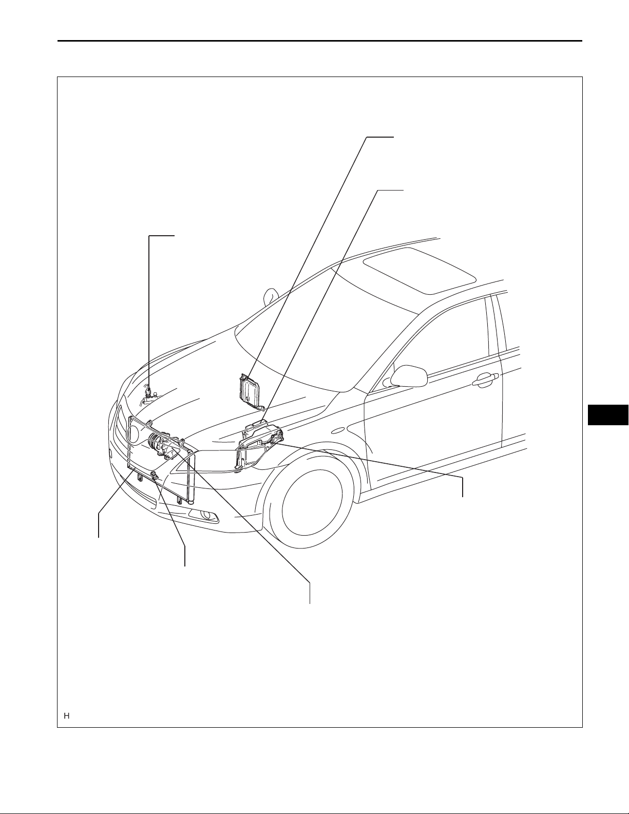
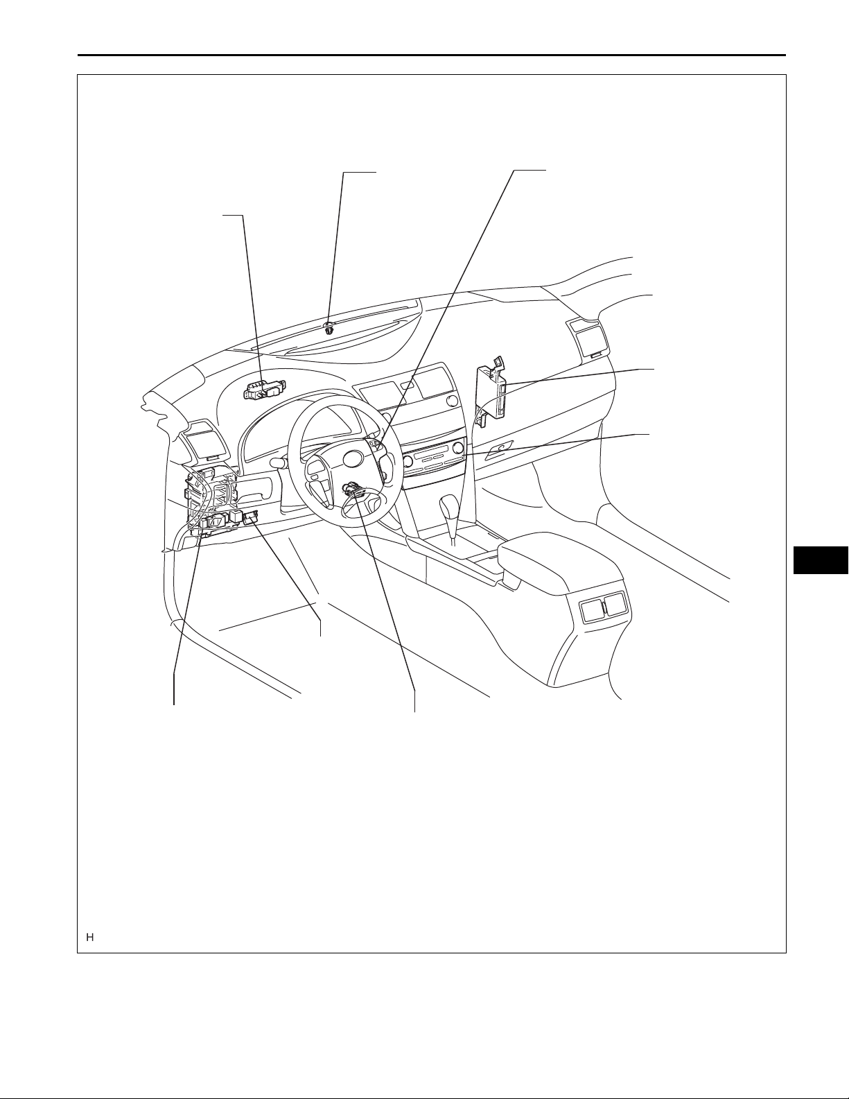
PARTS LOCATION
AIR CONDITIONING
PRESSURE SENSOR
AC–3
ECM (for 2GR-FSE)
ECM (for 2AZ-FE)
CONDENSER
AMBIENT
TEMPERATURE
SENSOR
ENGINE ROOM RELAY BLOCK
AND JUNCTION BLOCK
-
HTR FUSE
-
MG CLT RELAY
COMPRESSOR AND MAGNETIC CLUTCH
COMPRESSOR AND PULLEY
(for 2AZ-FE)
AC
(for 2GR-FSE)
E124494E01
AC–4
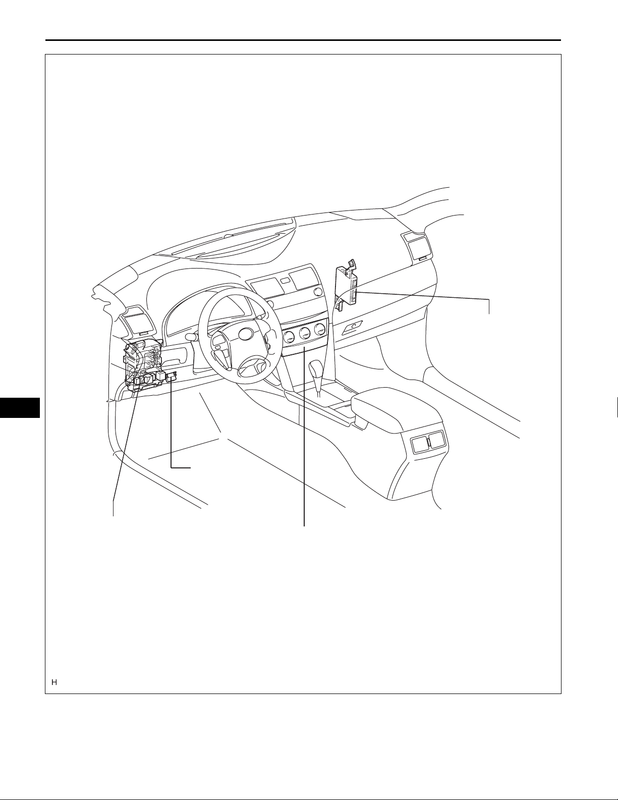
MANUAL A/C:
AIR CONDITIONING – AIR CONDITIONING SYSTEM
AC
INSTRUMENT PANEL
JUNCTION BLOCK
-
A/C NO. 2 FUSE
-
A/C FUSE
A/C AMPLIFIER
DLC3
A/C CONTROL ASSEMBLY
E124498E01
AUTO A/C:
AIR CONDITIONING – AIR CONDITIONING SYSTEM
AC–5
ION GENERATOR
(PLASMACLUSTER )
TM
SOLAR
SENSOR
STEERING PAD SWITCH
A/C AMPLIFIER
A/C CONTROL
ASSEMBLY
AC
INSTRUMENT PANEL
JUNCTION BLOCK
-
MAIN BODY ECU
-
A/C NO. 2 FUSE
-
A/C FUSE
DLC3
ROOM TEMPERATURE
SENSOR
E124496E01

AC–6
EVAPORATOR
AIR CONDITIONING – AIR CONDITIONING SYSTEM
AIR INLET CONTROL
SERVO MOTOR
AIR OUTLET CONTROL
SERVO MOTOR
EXPANSION VALVE
AC
AIR MIX CONTROL
SERVO MOTOR
(for DRIVER SIDE)
EVAPORATOR
TEMPERATURE
SENSOR
HEATER RADIATOR UNIT
SUB-ASSEMBLY
AIR CONDITIONING
HARNESS
BLOWER MOTOR
AIR MIX CONTROL
SERVO MOTOR
(for FRONT
PASSENGER
SIDE)
E124499E01
Auto A/C, Manual A/C:
AIR CONDITIONING – AIR CONDITIONING SYSTEM
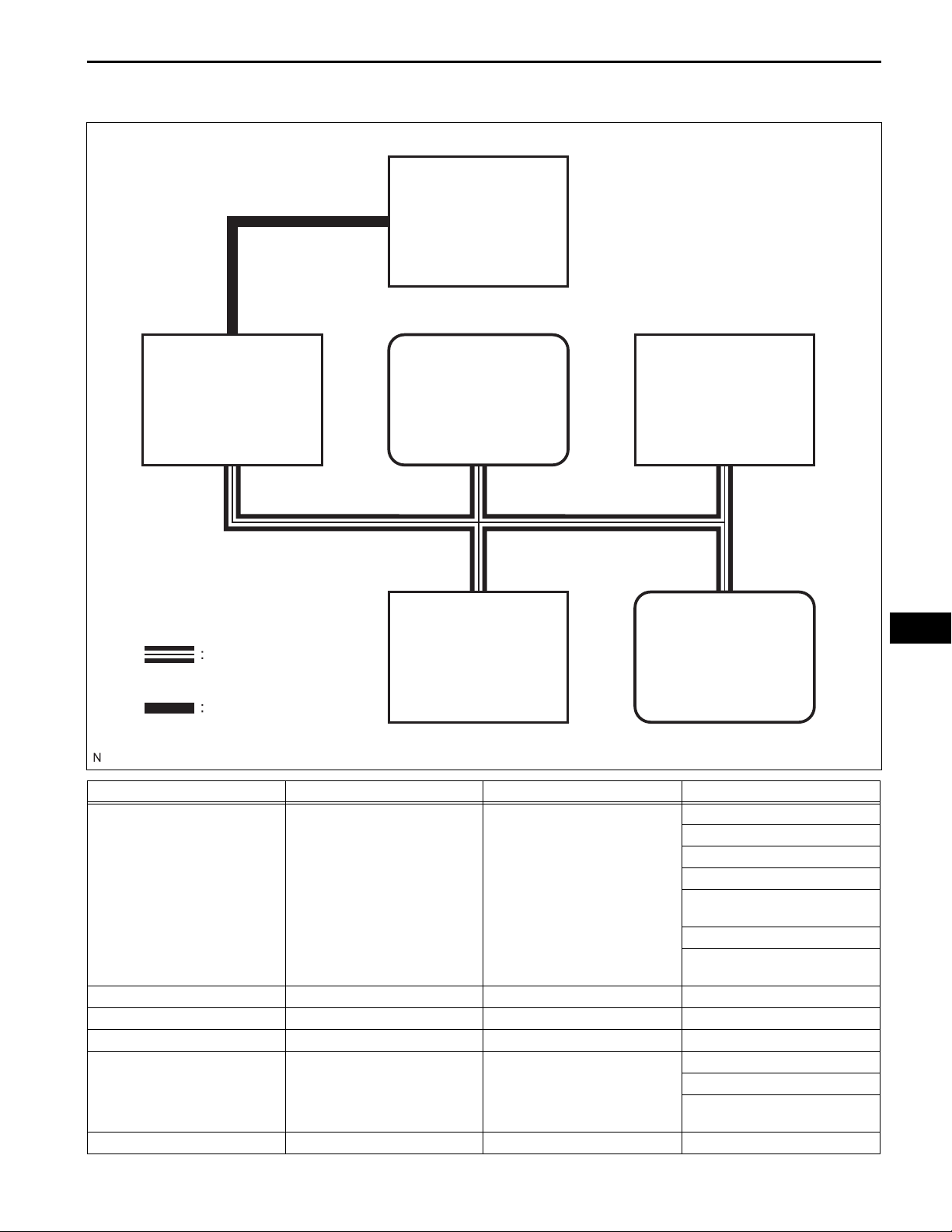
SYSTEM DIAGRAM
A/C Control Assembly
AC–7
A/C Amplifier
CAN (V-BUS)
Main Body ECU
Combination Meter
DLC3
ECM
LIN
Transmitter Receiver Line Signal
Magnetic Clutch Request Signal
Heater Idle Up Request Signal
A/C Idle Up Request Signal
Outside Temperature Data
A/C Amplifier ECM CAN
A/C Amplifier Combination Meter CAN Outside Temperature Data
A/C Amplifier DLC3 CAN Diagnostic Tool Response
A/C Amplifier A/C Control Assembly LIN A/C Operating State Signal
Main Body ECU A/C Amplifier CAN
Combination Meter A/C Amplifier CAN Vehicle Speed Signal
External Variable Control
Solenoid Current Signal
Prior A/C Control Request Signal
Refrigerant Gas Pressure Sensor
Signal
Auto Dimmer Signal
Destination Package
Destination Symbol Steering
Wheel
AC
E124510E01
AC–8
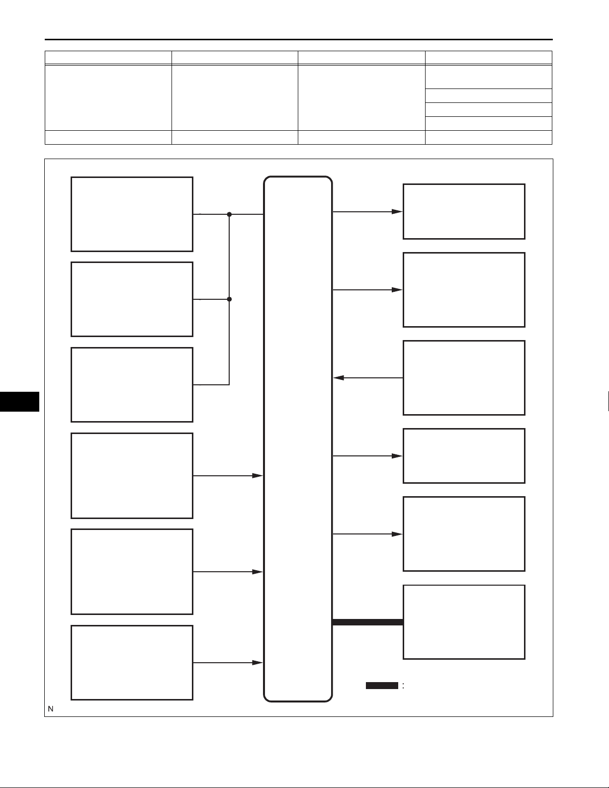
Transmitter Receiver Line Signal
ECM A/C Amplifier CAN
A/C Control Assembly A/C Amplifier LIN A/C Operation Signal
AIR CONDITIONING – AIR CONDITIONING SYSTEM
Engine Coolant Temperature
Signal
Engine rpm Data
A/C Control Cut-off Signal
A/C-E/G Cooperation Control
Manual A/C:
AC
Air Mix Control
Servo Motor
Air Inlet Control
Servo Motor
Air Outlet Control
Servo Motor
A/C Ambient Temperature
Sensor
A/C Solenoid
A/C Magnetic Clutch
(for 2GR-FSE)
A/C Pressure Sensor
A/C Amplifier
Blower Motor
A/C Evaporator
Temperature Sensor
A/C Lock Sensor
(for 2GR-FSE)
Rear Defogger Relay
A/C Control Assembly
LIN
E124512E01
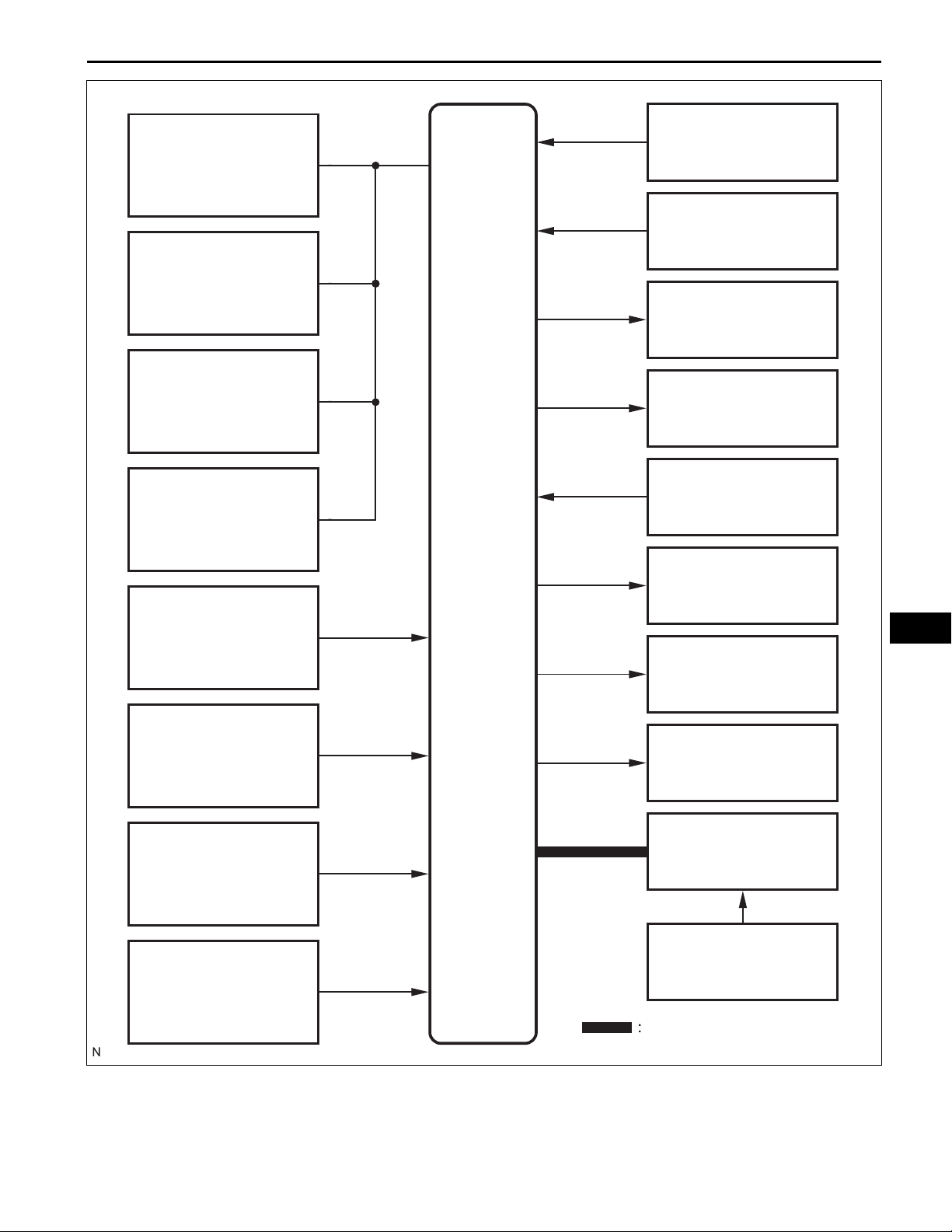
Auto A/C:
Air Mix Control Servo
Motor (for Driver Side)
Air Mix Control Servo
Motor (for Front Passenger
Side)
AIR CONDITIONING – AIR CONDITIONING SYSTEM
A/C Solar Sensor (for
Front Passenger Side)
AC–9
A/C Solar Sensor
(for Driver Side)
A/C Solenoid
Air Inlet Control
Servo Motor
Air Outlet Control
Servo Motor
A/C Room Temperature
Sensor
A/C Ambient Temperature
Sensor
A/C
Amplifier
A/C Magnetic Clutch
(for 2GR-FSE)
A/C Lock Sensor
(for 2GR-FSE)
Plasmacluster
(Ion Generator)
Blower Motor
Rear Defogger Relay
TM
AC
A/C Evaporator
Temperature Sensor
A/C Pressure Sensor
A/C Control Assembly
Steering Pad Switch
Assembly
LIN
E124511E01

AC
AC–10
Control Outline Manual A/C Automatic A/C
Neural Network Control
Manual Control
Outlet Air Temp. Control
Blower Control
Air Outlet Control
Air Inlet Control
Compressor Control
MAX A/C Control
Rear Window Defogger
Control
Outside Temperature
Indication Control
Self-Diagnosis
AIR CONDITIONING – AIR CONDITIONING SYSTEM
SYSTEM DESCRIPTION
1. GENERAL
The air conditioning system has the following controls:
This control is capable of effecting complex control by artificially
simulating the information processing method of the nervous system
of living organisms in order to establish a complex input / output
relationship that is similar to a human brain.
The A/C amplifier controls the damper positions (air inlet control
damper, air mix control damper and mode control damper) and blower
speed in accordance with the positions of the switches (temperature
control switch, blower switch, mode select switch and air inlet control
switch).
Based on the temperature set at the temperature control switch, the
neural network control calculates the outlet air temperature based on
the input signals from various sensors.
The temperature setting for the driver and front passenger are
controlled independently in order to provide a separate vehicle interior
temperatures for the right and left side of the cabin. Thus, air
conditioning that accommodates the occupants' preferences has been
realized.
Controls the blower motor in accordance with the airflow volume that
has been calculated by the neural network control based on the input
signals from various sensors.
Automatically switches the air outlets in accordance with the outlet
mode that has been calculated by the neural network control based on
the input signals from various sensors.
In accordance with the engine coolant temperature, outside air
temperature, amount of sunlight, required blower, outlet temperature,
and vehicle speed conditions, this control automatically switches the
blower outlet to the FOOT / DEF mode to prevent the windows from
becoming fogged when the outside air temperature is low.
Automatically controls the air inlet control damper to achieve the
calculated required outlet air temperature.
Drives the servo motor (for air inlet) according to the operation of the
air inlet control switch and moves the dampers to the FRESH or
RECIRC position.
Through the calculation of the target evaporator temperature based on
various sensor signals, the A/C amplifier optimally controls the
discharge capacity by regulating the opening extent of the A/C
compressor solenoid valve.
The A/C amplifier compares the A/C pulley speed signals, which are
transmitted by the lock sensor located on the A/C compressor, with
the engine speed signals, which are transmitted by the ECM
(crankshaft position sensor). When the A/C amplifier determines that
the A/C pulley is locked, it turns off the magnetic clutch. (for 2GR-FE)
When the temperature control switch is in the MAX A/C position, the
A/C amplifier turns the compressor on and activates the servomotor
(air inlet) to set the air inlet control damper to the RECIRC position,
improving the cooling efficiency.
Switches the rear defogger and outside rear view mirror heaters on for
15 minutes when the rear defogger button is pressed. Switches them
off if the button is pressed while they are operating.
Calculates the outside temperature using signals transmitted by the
outside temperature sensor. Calculated values are corrected by the A/
C amplifier and then indicated on the multi-information display.
A DTC (Diagnostic Trouble Code) is stored in the memory when the A/
C amplifier detects a problem with the air conditioning system.
- {
{ -
- {
- {
- {
- {
- {
- {
- {
{{
{{
{ -
{{
{{
{{

AIR CONDITIONING – AIR CONDITIONING SYSTEM
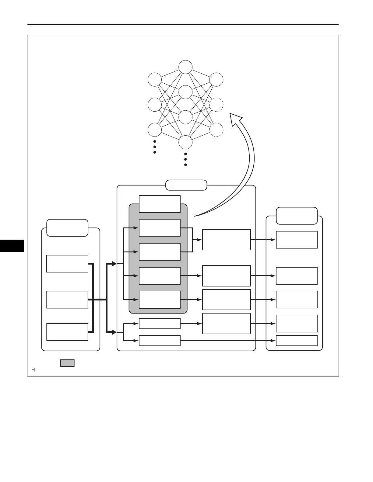
2. NEURAL NETWORK CONTROL
• In previous automatic air conditioning systems, the A/
C amplifier determined the required outlet air
temperature and blower air volume in accordance
with the calculation formula that has been obtained
based on information received from the sensors.
However, because the senses of a person are rather
complex, a given temperature is sensed differently,
depending on the environment in which the person is
situated. For example, a given amount of solar
radiation can feel comfortably warm in a cold climate,
or extremely uncomfortable in a hot climate.
Therefore, as a technique for effecting a higher level
of control, a neural network has been adopted in the
automatic air conditioning system. With this
technique, the data that has been collected under
varying environmental conditions is stored in the A/C
amplifier. The A/C amplifier can then effect control to
provide enhanced air conditioning comfort.
• The neural network control consists of neurons in the
input layer, intermediate layer, and output layer. The
input layer neurons process the input data of the
outside temperature, the amount of sunlight, and the
room temperature based on the outputs of the
switches and sensors, and output them to the
intermediate layer neurons. Based on this data, the
intermediate layer neurons adjust the strength of the
links among the neurons. The sum of these is then
calculated by the output layer neurons in the form of
the required outlet temperature, solar correction,
target airflow volume, and outlet mode control
volume. Accordingly, the A/C amplifier controls the
servo motors and blower motor in accordance with
the control volumes that have been calculated by the
neural network control.
AC–11
AC
AC–12
AIR CONDITIONING – AIR CONDITIONING SYSTEM
Intermediate Layer
Outer LayerInput Layer
AC
Input Processing
Temp. Setting
Ambient Temp.
Amount of Sunlight
Room Temp.
Neural Network
Terget Outlet Temp.
Amount of Sunlight
Correction
Target Airflow
Volume
Control
Target Output Temp.
Temp. Control
Correction
Various Types of Airflow
Volume Correction
Outlet Processing
Air Mix Control
Damper
Blower Motor
Sensor Input
Switch Input
Outlet Mode
Inlet Mode
Compressor
: Neural Network Operation Range
Various Types of
Mode Correction
Various Types of
Correction
Mode Control
Damper
Air Inlet Control
Damper
Compressor
E116942E01
AIR CONDITIONING – AIR CONDITIONING SYSTEM
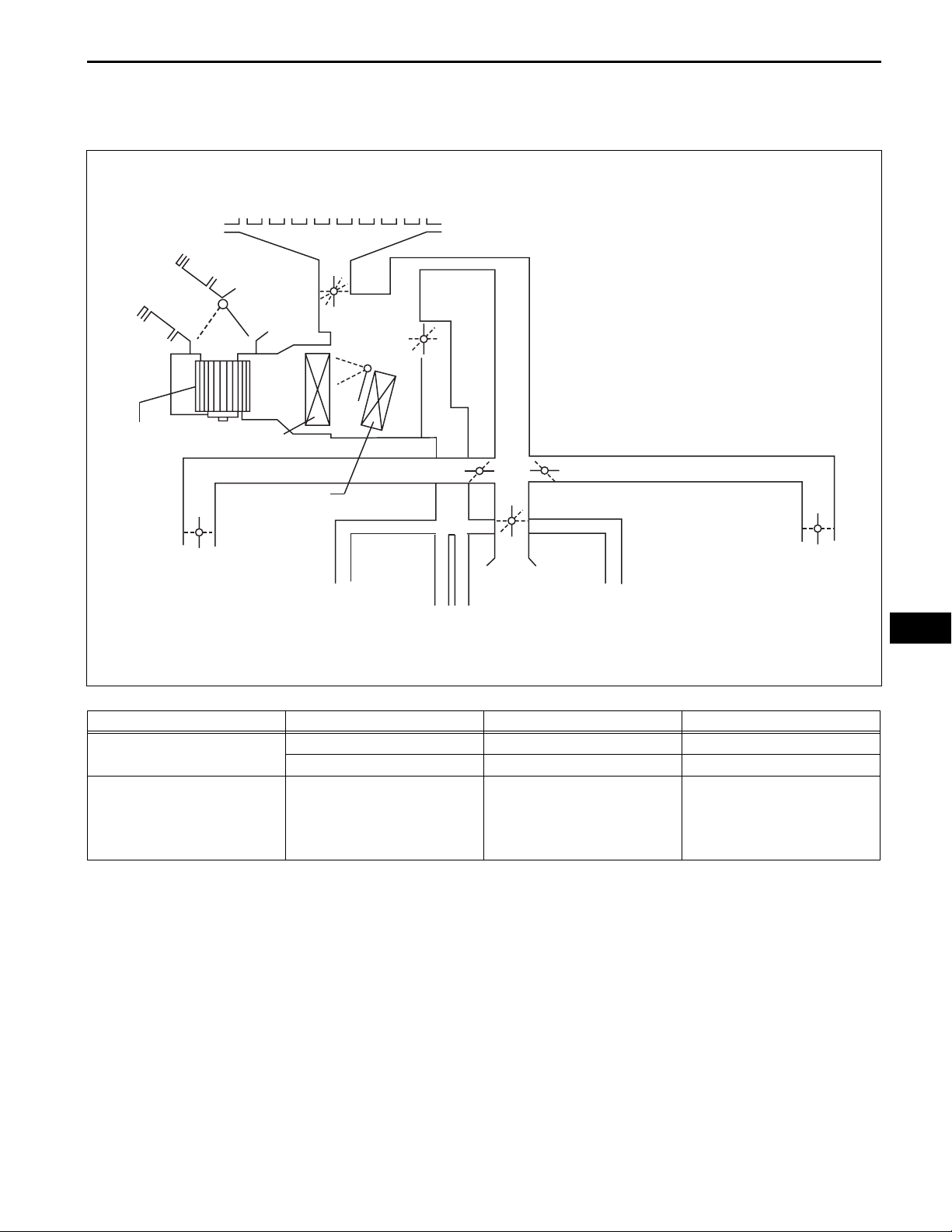
3. MODE POSITION AND DAMPER OPERATION
(a) Mode Position and Damper Operation (for Manual
A/C)
Center Defroster
AC–13
Side Defroster
Fresh Air
Recirc. Air
A
B
Blower Motor
Evaporator
Heater Core
Side Register
Front Foot Well
Register Duct
Y
Functions of Main Dampers:
Control Damper Operation Position Damper Position Operation
Air Inlet Control Damper
Air Mix Control Damper
Side Defroster
F
G
H
I
E
S
Q
R
D
C
J
K
M
O
P
L
N
Front Center
Register
Rear Foot Well
Front Foot Well
Register Duct
Register Duct
FRESH A Brings in fresh air.
RECIRC B Recirculates internal air.
Varies the mixture ratio of the
MAX COLD to MAX HOT
Temperature Setting
C - D - E
fresh air and the recirculation air
in order to regulate the
temperature continuously from
HOT to COLD.
Side Register
AC
E133954E01
AC–14
Control Damper Operation Position Damper Position Operation
Air Outlet Control Damper
AIR CONDITIONING – AIR CONDITIONING SYSTEM
DEF
F, J, L, P, S
FOOT / DEF
G, J, L, P, Q
FOOT
H, J, L, P, Q
BI-LEVEL
I, K, N, O, R
Defrosts the windshield through
the center defroster, side
defroster, side register, and rear
register.
Defrosts the windshield through
the center defroster, side
defroster, side register, and rear
register, while air is also blown
out from the front and rear foot
well register ducts.
Air blows out of the foot well
register duct and side register. In
addition, air blows out slightly
from the center defroster and side
defroster.
Air blows out of the front center
register, side register and front
and rear foot well register ducts.
AC
Side Defroster
Fresh Air
Blower Motor
Recric. Air
AB
Evaporator
Heater Core
FACE
Center Defroster
F
G
H
I
E
D
C
V
I, K, M, O, S
Air blows out of the front center
register and side register.
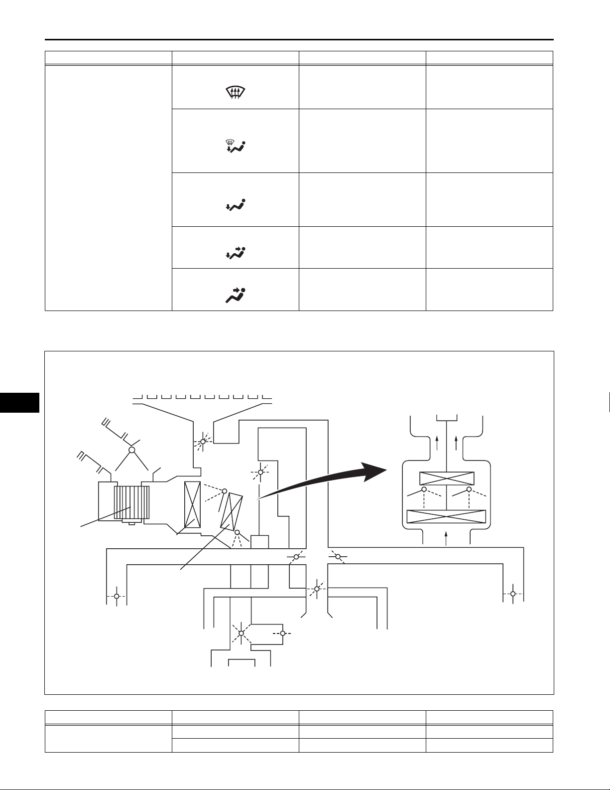
(b) Mode Position and Damper Operation (for
Automatic A/C)
Side Defroster
S
Q
R
T
U
K
J
L
M
P
N
O
To Driver Side
E
C
D
To Passenger Side
E‘
C‘
D‘
Side Register
Front Foot Well Register Dust
Rear Foot Well Register Dust
Y
Functions of Main Dampers:
Control Damper Operation Position Damper Position Operation
Air Inlet Control Damper
X
W
FRESH A Brings in fresh air.
RECIRC B Recirculates internal air.
Y
Front Center Register
Raer Center Register
Front Foot Well Register Dust
Side Register
C118756E03
AIR CONDITIONING – AIR CONDITIONING SYSTEM
Control Damper Operation Position Damper Position Operation
Varies the mixture ratio of the
Air Mix Control Damper
Air Outlet Control Damper
MAX COLD to MAX HOT
Temperature Setting
DEF
FOOT / DEF
FOOT
BI-LEVEL
FACE
C - D - E
(C' - D' - E')
T - U - V
F, J, L, P, S, Y
G, J, L, P, Q, X
H, J, L, P, Q, X
I, K, N, O, R, X
I, K, M, O, S, W
fresh air and the recirculation air
in order to regulate the
temperature continuously from
HOT to COLD.
Defrosts the windshield through
the center defroster, side
defroster, and side register.
Defrosts the windshield through
the center defroster, side
defroster, side register, and rear
center register, while air is also
blown out from the front and rear
foot well register ducts.
Air blows out of the foot well
register dust, and side register. In
addition, air blows out slightly
from the center defroster and side
defroster.
Air blows out of the front and rear
center registers, side register and
front and rear foot well register
ducts.
Air blows out of the front and rear
center registers, and side
register.
AC–15
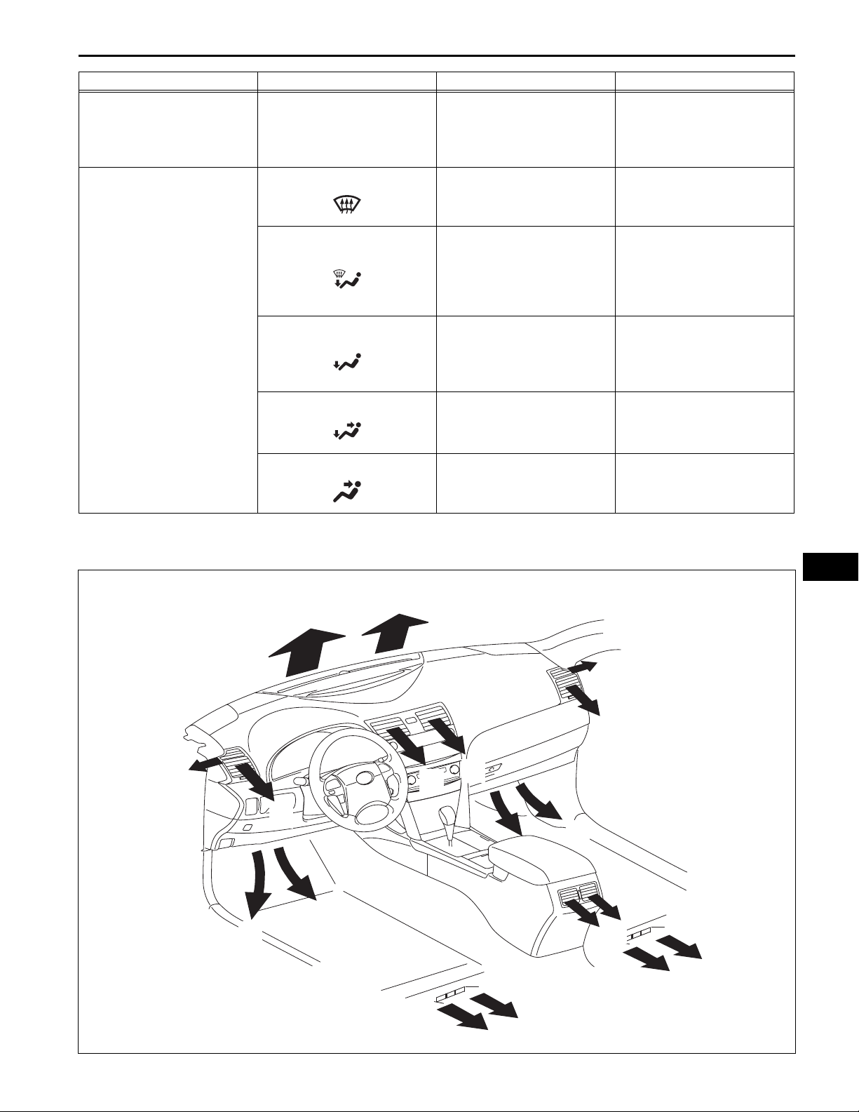
4. AIR OUTLETS AND AIRFLOW VOLUME
(a) Air Outlets and Airflow Volume
AC
F
G
B
D
D
F
G
B
A
A
D
D
C
E
Y
E
E133944E02
AC–16
AIR CONDITIONING – AIR CONDITIONING SYSTEM
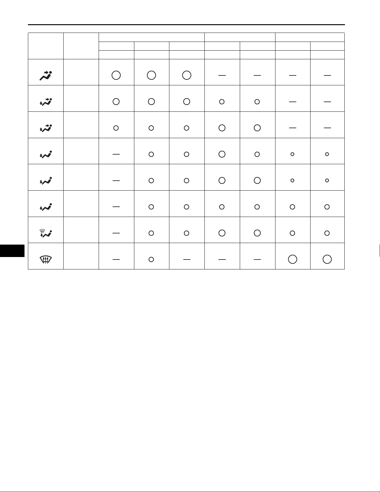
INDICATION
(MODE)
FACE
B/L-U*1
B/L-L*2
FOOT-F*3
FOOT-R*4
FOOT-D*5
SELECTION
(Auto /
Manual)
{ / {
{ / {
{ / -
{ / {
{ / -
{ / -
FACE FOOT DEF
CTR SIDE RR FR RR CTR SIDE
ABC*6DEFG
AC
F/D
{ / {
DEF
{ / {
The size of the circle { indicates the proportion of
airflow volume.
*1: Greater airflow volume at the upper area
*2: Greater airflow volume at the lower area
*3: Greater airflow volume at the front
*4: Greater airflow volume at the rear
*5: Greater airflow volume at the defroster
*6: Only for models with automatic air conditioning.
5. PLASMACLUSTER ION GENERATOR CONTROL
(a) General:
(1) A Plasmacluster ion generator is provided inside
the air duct of the side register on the driver seat
side to improve the air quality and comfort in the
cabin.
(2) This generator is controlled by the A/C amplifier
and operates in conjunction with the blower
motor.
NOTICE:
• The Plasmacluster ion generator uses a
high voltage, which is hazardous.
Therefore, if the Plasmacluster ion
generator requires repairs, be sure to
have them done at a TOYOTA dealer.

AIR CONDITIONING – AIR CONDITIONING SYSTEM
• Do not apply any type of spray (such as a
cleaning solvent or hair spray) or stick
any foreign matter into the Plasmacluster
ion outlet, as this could cause improper
operation or a malfunction.
• After use, dust may accumulate around
the side register on the driver seat side. If
this occurs, press the OFF switch on the
heater control panel to stop the blower
motor before cleaning the area.
• It is normal for the Plasmacluster ion
generator to emit a slight sound during
operation. This sound is created when
electrons collide with the electrode while
Plasmacluster ions are being generated.
HINT:
Plasmacluster
plasmacluster ions are a trademark of the
SHARP Corporation.
(b) Operation:
(1) The Plasmacluster ion generator produces
positive and negative ions from the water
molecules (H2O) and oxygen molecules (O2) in
the air, and emits them into the air. These ions
reduce airborne germs.
6. BLOWER MOTOR
The blower motor has a built-in blower controller, and is
controlled with duty control from the A/C amplifier.
TM
, plasmacluster, and
AC–17
AC
AC–18
AIR CONDITIONING – AIR CONDITIONING SYSTEM
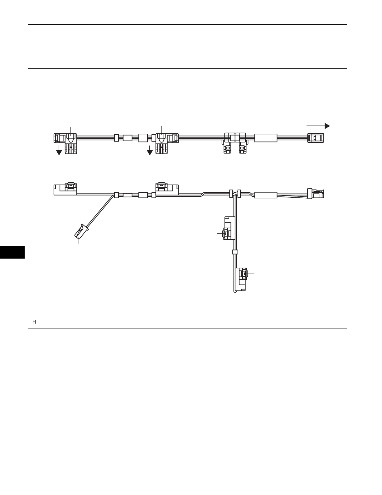
7. BUS CONNECTOR
(a) A BUS connector is used in the wire harness
connection that connects the servo motor from the
A/C amplifier.
Top View:
AC
Bus Connector
To Air Mix Servo Motor
(For Driver)
Evaporator
Temp. Sensor
Bus Connector
To Air Inlet Servo Motor
Bus Connector
To Air Outlet
Servo Motor
To A/C Amplifier
Side View:
Bus Connector
To Air Mix Servo Motor
(For Front Passenger)
E116948E01
AIR CONDITIONING – AIR CONDITIONING SYSTEM
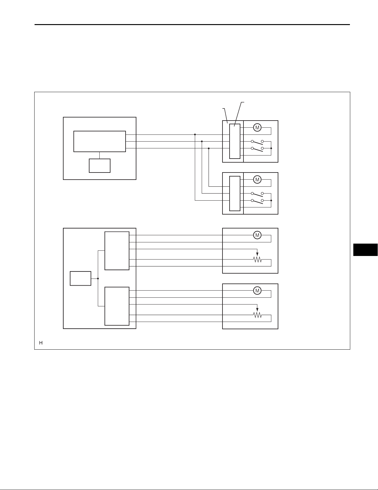
(b) The BUS connector has a built-in communication/
driver IC which communicates with each servo
motor connector, actu ates the se rvo mot or, and has
a position detection function. This enables bus
communication for the servo motor wire harness, for
a more lightweight construction and a reduced
number of wires.
AC–19
with BUS Connector:
A/C Amplifier
Communication IC
CPU
without BUS Connector:
A/C Amplifier
CPU
BUS Connector
Communication/Driver IC
Servo Motor
Drive IC
AC
Servo Motor
Drive IC
E116949E01
AC–20
AIR CONDITIONING – AIR CONDITIONING SYSTEM
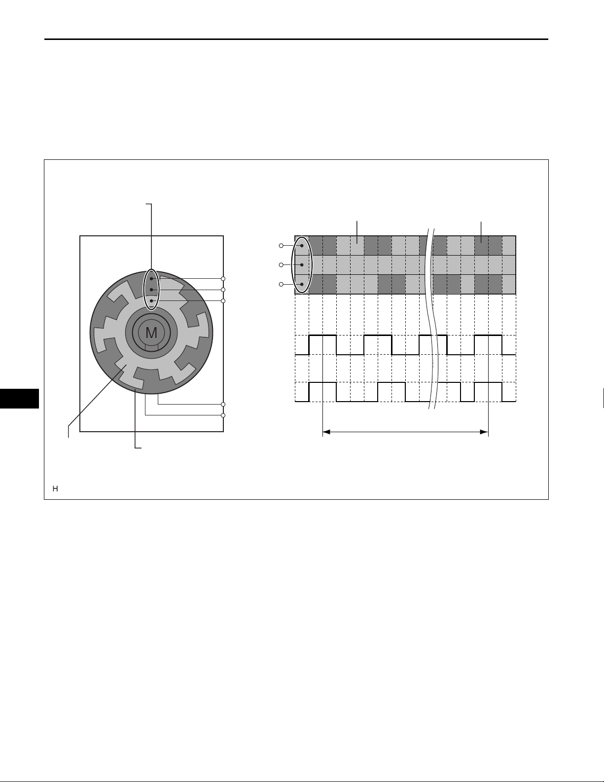
8. SERVO MOTOR
(a) The pulse pattern type servo motor consists of a
printed circuit board and servo motor. The printed
circuit board has three contact points, and transmit s
to the A/C amplifier two ON-OFF signals for the
difference of the pulse phase. The BUS connector
detects the damper position and movement
direction with this signal.
AC
Contact Points
Portion
Conductive Portion
Contact Points
A
GND
A
B
GND
Printed-circuit BoardConductive
B
Hi
A
Lo
Hi
B
Lo
1 Rotation
Printed-circuit Board
E116950E01
9. A/C COMPRESSOR
(a) General
(1) The A/C compressor is a continuously variable
capacity type in which its capacity ca n be varied
in accordance with the cooling load of the air
conditioning.
(2) This compressor consists of the A/C pulley,
shaft, lug plate, swash plate, piston, shoe, crank
chamber, cylinder, and solenoid valve.
(3) The A/C pulley with built-in magnetic clutch and
the lock sensor that detects whether the
magnetic clutch is locked are installed on
models with the 2GR-FE.
(4) The DL (Damper Limiter) type A/C pulley is
installed on models with the 2AZ-FE.
(5) A solenoid valve that adjusts the suction
pressure so that the compressor capacity can be
controlled as desired is provided.

AIR CONDITIONING – AIR CONDITIONING SYSTEM
(6) The internal valve is provided on models with
2AZ-FE to improve the A/C compressor
durability under the high speed and large
thermal load conditions. The internal valve is
integrated into the solenoid valve.
(b) Solenoid Valve Operation
(1) The crank chamber is connected to the
discharge passage. A solenoid valve is provided
between the discharge passage (LO pressure)
and the discharge passage (HI pressure).
(2) The solenoid valve operates under duty cycle
control in accordance with the signals from A/C
amplifier.
(3) When the solenoid valve closes (solenoid coil is
energized), a difference in pressure is created
and the pressure in the crank chamber
decreases. Then, the pressure that is applied to
the right side of the piston becomes greater than
the pressure that is applied to the left side of the
piston. This compresses the spring and tilts the
swash plate. As a result, the piston stroke
increases and the discharge capacity increases.
(4) When the solenoid valve opens (solenoid coil is
not energized), the difference in pressure
disappears. Then, the pressure that is applied to
the left side of the piston becomes the same as
the pressure that is applied to the right side of
the piston. Thus, the spring elongates and
eliminates the tilt of the swash plate. As a result,
there is no piston stroke and the discharge
capacity is reduced.
(c) Internal Valve Operation (for 2AZ-FE)
(1) The internal valve operates when the A/C
compressor speed has increased rapidly, the A/
C compressor speed is high, or when thermal
load has suddenly changed. As a result, the A/C
compressor capacity is reduced, increasing the
durability of the A/C compressor.
(d) DL type A/C Pulley (for 2AZ-FE)
(1) This pulley contains a damper to absorb the
torque fluctuations of the engine and a limiter
mechanism to protect the drive belt in case the
compressor locks. In the event that the
compressor locks, the limiter mechanism causes
the spoke portion of the pulley to break, thus
separating the pulley from the compressor.
10. LOCK SENSOR (for 2GR-FE)
The lock sensor sends A/C pulley speed signals to the A/
C amplifier. The A/C amplifier determines whether the
magnetic clutch is locked or not by using those signals
and engine speed signals.
AC–21
AC
AC–22
AIR CONDITIONING – AIR CONDITIONING SYSTEM
11. ROOM TEMPERATURE SENSOR (for AUTO A/C)
The room temperature sensor detects the cabin
temperature based on changes in the resistance of its
built-in thermistor and sends a signal to the A/C
amplifier.
12. AMBIENT TEMPERATURE SENSOR
The ambient temperature sensor detects the outside
temperature based on changes in the resistance of its
built-in thermistor and sends a signal to the A/C
amplifier.
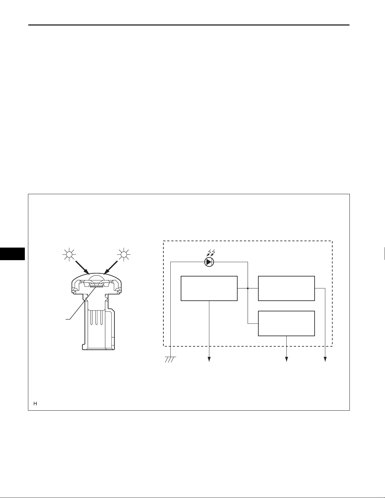
13. SOLAR SENSOR (for AUTO A/C)
(a) The solar sensor consists of a photo diode, two
amplifier circuits for the solar sensor , and frequency
converter circuit for the light control sensor.
(b) A solar sensor detects (in the form of changes in the
current that flows through the built-in photo diode)
the changes in the amount of sunlight from the LH
and RH sides (2 directions) and outputs these
sunlight strength signals to the A/C amplifier.
AC
LH Side RH Side
Sensor
Portion
Internal circuit of the solar sensor
Photo Diode
Frequency
Convert Circuit
To Main Body ECU
Amplifier Circuit
(LH)
Amplifier Circuit
(RH)
To A/C Amplifier
E116951E01
14. EVAPORATOR TEMPERATURE SENSOR
The evaporator temperature sensor detects the
temperature of the cool air immediately past the
evaporator in the form of resistance changes, and
outputs it to the A/C amplifier.

AIR CONDITIONING – AIR CONDITIONING SYSTEM
15. A/C PRESSURE SENSOR
The A/C pressure sensor detects the refrigerant
pressure and outputs it to the A/C amplifier in the form of
voltage changes.
AC–23
AC
AC–24
1
NEXT
2
AIR CONDITIONING – AIR CONDITIONING SYSTEM
HOW TO PROCEED WITH
TROUBLESHOOTING
HINT:
• Use the following procedures to troubleshoot the air
conditioning system.
• *: Use the intelligent tester.
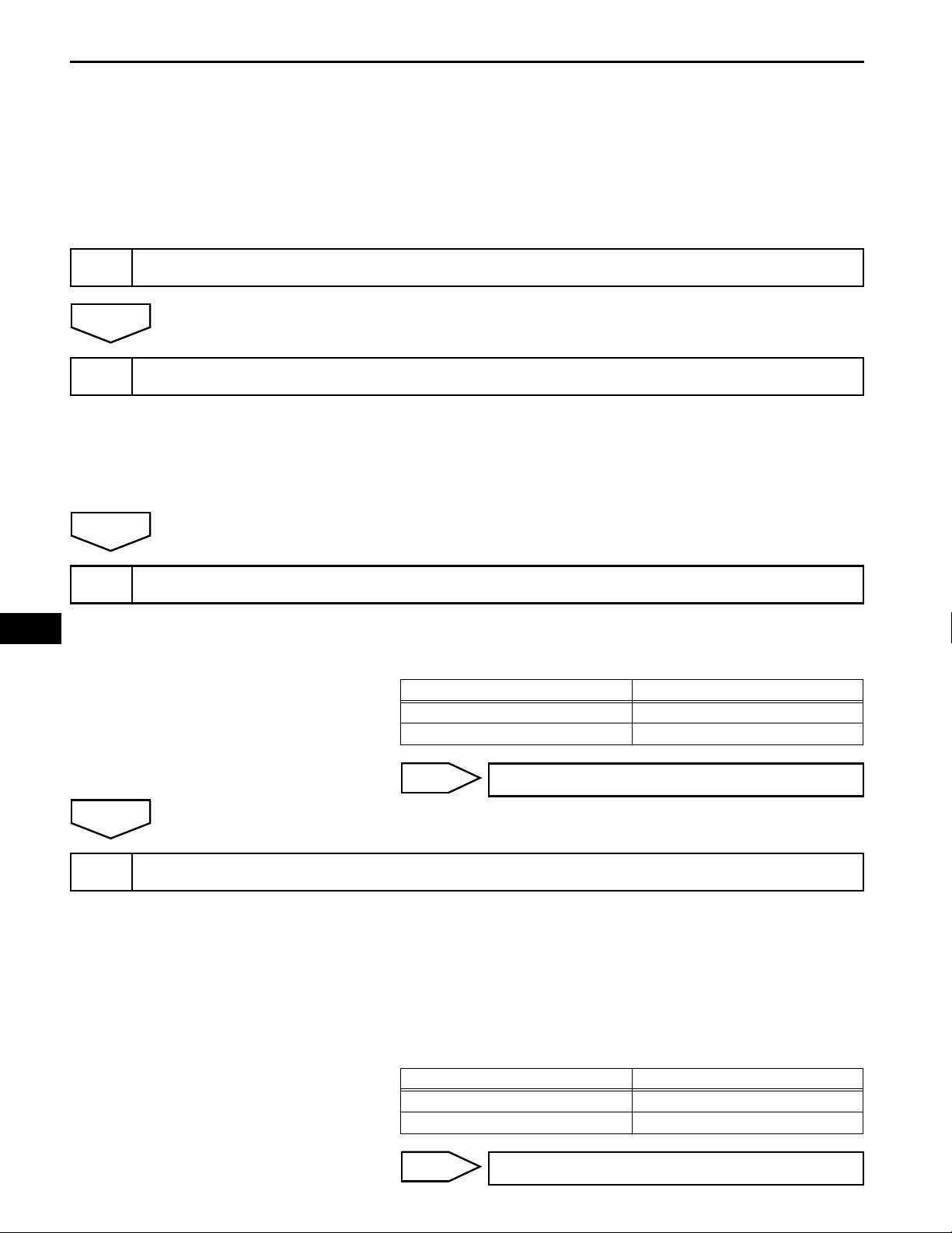
VEHICLE BROUGHT TO WORKSHOP
INSPECT BATTERY VOLTAGE
(a) Inspect the battery voltage.
Standard voltage:
11 to 14 V
If the voltage is below 11 V, recharge or replace the
battery before proceeding.
AC
NEXT
3
A
4
CHECK COMMUNICATION FUNCTION OF CAN COMMUNICATION SYSTEM*
(a) Use the intelligent tester to check if the CAN
Communication System is functioning normally.
Result
Result Proceed to
CAN DTC is not output A
CAN DTC is output B
B
CHECK FOR DTC*
(a) Check for DTCs and note any codes that are output.
HINT:
Refer to the DTC CHECK / CLEAR (See page AC-32).
(b) Delete the DTCs.
(c) Recheck for DTCs. Based on the DTCs output above, try
to force output of the A/C system DTC by simulating the
operation indicated by the DTC.
Result
Go to CAN COMMUNICATION SYSTEM
Result Proceed to
DTC is not output A
DTC is output B
B
Go to step 7
AIR CONDITIONING – AIR CONDITIONING SYSTEM
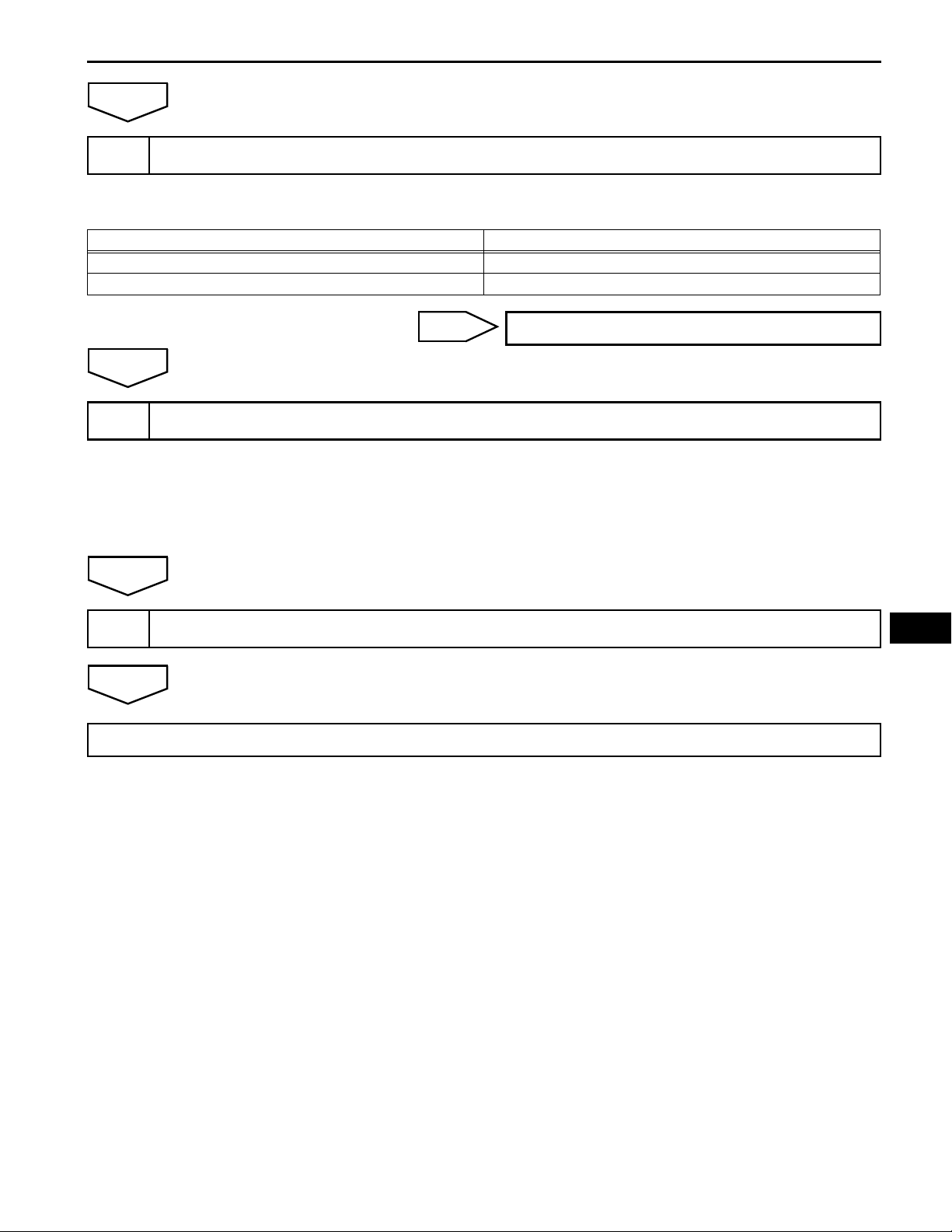
A
PROBLEM SYMPTOMS TABLE
5
(a) Refer to the problem symptoms table (See page AC-25).
Result
Result Proceed to
Fault is not listed in problem symptoms table A
Fault is listed in problem symptoms table B
AC–25
6
NEXT
7
NEXT
END
B
A
OVERALL ANALYSIS AND TROUBLESHOOTING*
(a) Actuator Check (See page AC-43 for AUTO A/C)
(b) DATA LIST / ACTIVE TEST (See page AC-38)
(c) Terminals of ECU (See page AC-29)
(d) On-vehicle Inspection
(e) Inspection
ADJUST, REPAIR OR REPLACE
Go to step 8
AC

AC
AC–26
AIR CONDITIONING – AIR CONDITIONING SYSTEM
AIR CONDITIONER (AUTO A/C)
DISPLAY (ITEM) DEFAULT CONTENTS SETTING
SET TEMP SHIFT
(Set Temperature Shift)
AIR INLET MODE
(Air Inlet Mode)
COMPRESSOR MODE
(Compressor Mode)
COMPRS / DEF OPER
(Compressor / Air Inlet DEF
Operation)
EVAP CTRL
(Evaporator Control)
FOOT / DEF MODE
(Foot / DEF auto mode)
AUTO BLOW UP
(Foot / DEF automatic blower up
function)
AMBIENT TMP SFT
(Ambient Temperature Shift)
NORMAL
NORMAL
AUTO
AUTO
LINK
AUTO
ON
ON
CUSTOMIZE PARAMETERS
HINT:
The following items can be customized.
NOTICE:
• When the customer requests a change in a function,
first make sure that the function can be customized.
• Be sure to make a note of the current settings before
customizing.
• When troubleshooting a function, first make sure that
the function is set to the default setting.
To shift the temperature against the displayed
temperature
In case of turning the A/C ON when you desire
to make the compartment cool down quickly,
this is the function to change the mode
automatically to RECIRCULATION mode
Function to turn the A/C ON automatically by
pressing the AUTO button when the blower is
ON and the A/C is OFF
Function to turn the A/C ON automatically
linked with the FRONT DEF button when the
A/C is OFF
Function to set the evaporator control to the
AUTOMATIC position (AUTO) to save power,
or to the coldest position (MANUAL) to
dehumidify the air and to prevent the windows
from fogging up
Function to turn the airflow from FOOT / DEF
ON automatically when AUTO MODE is ON
Function to change the blower level
automatically when the defroster is ON
Function to shift the ambient temperature
against the displayed ambient temperature
+2 C / +1 C / NORMAL / -1 C / -2
C
MANUAL / AUTO
MANUAL / AUTO
NORMAL / LINK
MANUAL / AUTO
OFF / ON
OFF / ON
+3 C / +2 C / +1 C / NORMAL / -1
C / -2 C / -3 C
AIR CONDITIONING – AIR CONDITIONING SYSTEM
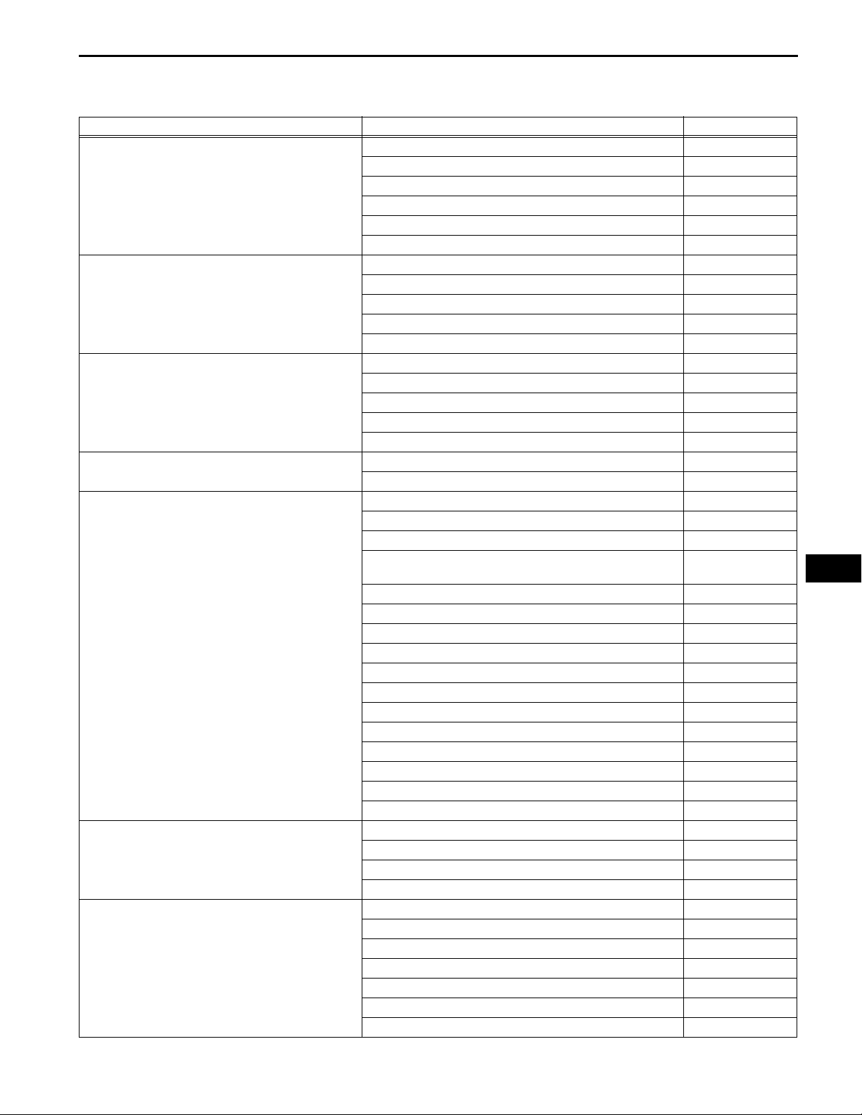
MANUAL A/C:
Symptom Suspected area See page
All functions of the A/C system do not operate
Air Flow Control: No blower operation
Air Flow Control: No blower control
Air Flow Control: Insufficient air flow
Temperature Control: No cool air comes out
Temperature Control: No warm air comes out
Temperature Control: Output air is warmer or cooler
than the set temperature or response is slow.
PROBLEM SYMPTOMS TABLE
1. IG power source circuit AC-113
2. Back-up power source circuit AC-116
3. Heater control panel power source circuit AC-98
4. LIN communication circuit AC-118
5. A/C control assembly AC-255
6. A/C amplifier AC-258
1. Blower motor circuit AC-91
2. Heater control panel power source circuit AC-98
3. LIN communication circuit AC-118
4. A/C control assembly AC-255
5. A/C amplifier AC-258
1. Blower motor circuit AC-91
2. Heater control panel power source circuit AC-98
3. LIN communication circuit AC-118
4. A/C control assembly AC-255
5. A/C amplifier AC-258
1. Blower motor circuit AC-91
2. A/C amplifier AC-258
1. Refrigerant volume AC-120
2. Refrigerant pressure AC-120
3. Pressure switch circuit AC-65
4. Air conditioning compressor magnetic clutch circuit (for
2GR-FSE)
5. Compressor lock sensor circuit (for 2GR-FSE) AC-61
6. Compressor solenoid circuit AC-84
7. Air mix control servo motor circuit AC-74
8. Evaporator temperature sensor circuit AC-53
9. Ambient temperature sensor circuit AC-49
10. Heater control panel power source circuit AC-98
11. LIN communication circuit AC-118
12. Expansion valve AC-159
13. A/C control assembly AC-255
14. A/C amplifier AC-258
15. ECM (for 2AZ-FE) ES-432
16. ECM (for 2GR-FSE) ES-518
1. Air mix control servo motor circuit AC-74
2. Evaporator temperature sensor circuit AC-53
3. Ambient temperature sensor circuit AC-49
4. A/C amplifier AC-258
1. Refrigerant volume AC-120
2. Refrigerant pressure AC-120
3. Ambient temperature sensor circuit AC-49
4. Air mix control servo motor circuit AC-74
5. Radiator unit sub-assembly AC-159
6. Expansion valve AC-159
7. A/C amplifier AC-258
AC-100
AC–27
AC

AC–28
Symptom Suspected area See page
Temperature control: No temperature control ( only
Max. cool or Max. warm)
No air inlet control
No air flow mode control
Engine idle up does not occur, or is continuous
Diagnostic trouble codes are not recorded. Set mode
is cleared when ignition switch is turned OFF.
AIR CONDITIONING – AIR CONDITIONING SYSTEM
1. Air mix control servo motor circuit AC-74
2. Ambient temperature sensor circuit AC-49
3. Evaporator temperature sensor circuit AC-53
4. A/C control assembly AC-255
5. A/C amplifier AC-258
1. Air inlet control servo motor circuit AC-77
2. A/C amplifier AC-258
1. Air outlet control servo motor circuit AC-79
2. A/C amplifier AC-258
1. Air conditioning compressor magnetic clutch circuit (for
2GR-FSE)
2. Compressor lock sensor circuit (for 2GR-FSE) AC-61
3. Compressor solenoid circuit AC-84
4. Heater control panel power source circuit AC-98
5. LIN communication circuit AC-118
6. A/C control assembly AC-255
7. A/C amplifier AC-258
8. ECM (for 2AZ-FE) ES-432
9. ECM (for 2GR-FSE) ES-518
1. Back-up power source circuit AC-116
2. A/C amplifier AC-258
AC-100
AC
AUTO A/C:
Symptom Suspected area See page
All functions of the A/C system do not operate
Air Flow Control: No blower operation
Air Flow Control: No blower control
Air Flow Control: Insufficient air flow
1. IG power source circuit AC-113
2. Back-up power source circuit AC-116
3. Heater control panel power source circuit AC-98
4. LIN communication circuit AC-118
5. Steering pad switch circuit AC-108
6. A/C control assembly AC-255
7. A/C amplifier AC-258
1. Blower motor circuit AC-91
2. Heater control panel power source circuit AC-98
3. LIN communication circuit AC-118
4. A/C control assembly AC-255
5. A/C amplifier AC-258
1. Blower motor circuit AC-91
2. Heater control panel power source circuit AC-98
3. LIN communication circuit AC-118
4. A/C control assembly AC-255
5. A/C amplifier AC-258
1. Blower motor circuit AC-91
2. A/C amplifier AC-258

AIR CONDITIONING – AIR CONDITIONING SYSTEM
Symptom Suspected area See page
Temperature Control: No cool air comes out
Temperature Control: No warm air comes out
Temperature Control: Output air is warmer or cooler
than the set temperature or response is slow.
Temperature control: No temperature contr o l (only
Max. cool or Max. warm)
No air inlet control
No air flow mode control
1. Refrigerant volume AC-120
2. Refrigerant pressure AC-120
3. Pressure switch circuit AC-65
4. Air conditioning compressor magnetic clutch circuit (for
2GR-FSE)
5. Compressor lock sensor circuit (for 2GR-FSE) AC-61
6. Compressor solenoid circuit AC-84
7. Air mix control servo motor circuit (Driver side) AC-82
8. Air mix control servo motor circuit (Passenger side) AC-74
9. Evaporator temperature sensor circuit AC-53
10. Room temperature sensor circuit AC-45
11. Ambient temperature sensor circuit AC-49
12. Heater control panel power source circuit AC-98
13. LIN communication circuit AC-118
14. Expansion valve AC-159
15. A/C control assembly AC-255
16. A/C amplifier AC-258
17. ECM (for 2AZ-FE) ES-432
18. ECM (for 2GR-FSE) ES-518
1. Air mix control servo motor circuit (Driver side) AC-82
2. Air mix control servo motor circuit (Passenger side) AC-74
3. Evaporator temperature sensor circuit AC-53
4. Room temperature sensor circuit AC-45
5. Ambient temperature sensor circuit AC-49
6. A/C amplifier AC-258
1. Refrigerant volume AC-120
2. Refrigerant pressure AC-120
3. Solar sensor circuit (Driver side) AC-69
4. Solar sensor circuit (Passenger side) AC-56
5. Room temperature sensor circuit AC-45
6. Ambient temperature sensor circuit AC-49
7. Air mix control servo motor circuit (Driver side) AC-82
8. Air mix control servo motor circuit (Passenger side) AC-74
9. Radiator unit sub-assembly AC-159
10. Expansion valve AC-159
11. A/C amplifier AC-258
1. Air mix control servo motor circuit (Driver side) AC-82
2. Air mix control servo motor circuit (Passenger side) AC-74
3. Room temperature sensor circuit AC-45
4. Ambient temperature sensor circuit AC-49
5. Evaporator temperature sensor circuit AC-53
6. Solar sensor circuit (Driver side) AC-69
7. Solar sensor circuit (Passenger side) AC-56
8. A/C control assembly AC-255
9. A/C amplifier AC-258
1. Air inlet control servo motor circuit
2. A/C amplifier AC-258
1. Air outlet control servo motor circuit AC-79
2. A/C amplifier AC-258
AC-100
AC-77
AC–29
AC

AC–30
Symptom Suspected area See page
Engine idle up does not occur, or is continuous
Blinking of A/C indicator
Unable to control A/C with the steering pad switch
Plasmacluster indicator does not come on
(Plasmacluster does not operate)
Diagnostic trouble codes are not recorded. Set mode
is cleared when ignition switch is turned OFF.
AIR CONDITIONING – AIR CONDITIONING SYSTEM
1. Air conditioning compressor magnetic clutch circuit (for
2GR-FSE)
2. Compressor lock sensor circuit (for 2GR-FSE) AC-61
3. Compressor solenoid circuit AC-84
4. Heater control panel power source circuit AC-98
5. LIN communication circuit AC-118
6. A/C control assembly AC-255
7. A/C amplifier AC-258
8. ECM (for 2AZ-FE) ES-432
9. ECM (for 2GR-FSE) ES-518
1. Compressor solenoid circuit AC-84
2. A/C amplifier AC-258
1. Steering pad switch circuit AC-108
2. Heater control panel power source circuit AC-98
3. LIN communication circuit AC-118
4. A/C control assembly AC-255
5. A/C amplifier AC-258
1. Blower motor circuit AC-91
2. Plasmacluster circuit AC-105
3. A/C amplifier AC-258
1. Back-up power source circuit AC-116
2. A/C amplifier AC-258
AC-100
AC
 Loading...